instruction manual en - testo€¦ · parameterizing, adjusting and analyzing software (p2a...
TRANSCRIPT

Instruction manual en
testo 6721 Dew point monitor P2A software for testo 6721

2
3
ContentsContents 3Safety and the environment 4
Part 1: testo 6721Specifications 5Commissioning 8
Assembling the instrument 8Wiring the instrument 9Connecting the instrument 11Parameterizing/adjusting/analyzing the instrument 11
Maintaining the product 11Tips and assistance 12
Part 2: testo P2A SoftwareSpecifications 13First steps 14
Installing the software/driver 14Starting the software 14
Product description 15Using the product 16Tips and assistance 19
????
Contents 3
de
enfr
esit
pt
svnl
4 Safety and the environment
Safety and the environment
About this document
Please read this documentation through carefully and familiarize yourself withthe product before putting it to use. Keep this documentation to hand sothat you can refer to it when necessary. Hand this documentation on to anysubsequent users of the product.
Pay particular attention to information emphasized by the following symbols:· Important.
Avoiding personal injury/damage to equipment
Never store the product together with solvents and do not use anydesiccants.
Only operate the product properly, for its intended purpose and within theparameters specified in the technical data. Do not use force.
Only carry out the maintenance and repair work that is described in thedocumentation. Follow the prescribed steps when doing so. Use only OEMspare parts from Testo.
Protecting the environment
Send the product back to Testo at the end of its useful life. We will ensurethat it is disposed of in an environmentally friendly manner.

5
de
enfr
esit
pt
svnl
????
testo 6721 - Specifications
PART 1: TESTO 6721
Specifications
Functions and use
The 6721 is a dew point monitor for monitoring trace humidity in the followingapplications:
· Trace humidity monitoring in compressed air systems, e.g. upstream of pneumaticmachines.
· Monitoring (compressed air) low-temperature driers.· Monitoring (compressed air) membrane driers.
The product must only be assembled, wired and connected by qualifiedpersonnel. The product must not be used in areas at risk of explosion!
Ordering overview0555 6721 Axx / Fxx / Kxx
A01 G½" process connectionA02 NPT ½" process connectionB01 Measuring range -30 to +30°CtdB02 Measuring range -45 to +30°CtdF01 Dew point °Ctd / GW 1 / GW 2 / hysteresisF02 Dew point °Ftd / GW 1 / GW 2 / hysteresis

6 testo 6721 - Specifications
Technical details
Dimensions:
➊ 0555 6721-A01: G½0555 6721-A02: NPT½"
➋ Installation depth in process➌ Wrench size
33
176
167
33
21ø
72
56 ➋
9242
➊
➌
Parameters, measuring range
· Dew point temperature (trace humidity): -30 to 30 °Ctd/-22 to 86 °Ftd (B01) | -45 to +30°Ctd/-49 to +86°Ftd (B02)
Accuracy
· Dew point temperature at 25 °C/77 °F processtemperature: ±4 K (-30…-20°Ctd/ -22…-4°Ftd),±3 K (-20…-10°Ctd/ -4…14°Ftd),±2 K (-10…0°Ctd/ 14…32°Ftd),±1 K (>0°Ctd/ >32°Ftd)
Resolution
· 0.1 °Ctd/0.1 °Ftd
Meas. cycle
· 1/s
Other instrument data
· Humidity sensor: Testo humidity sensor (with specialtrace humidity adjustment)
· Temperature sensor: NTC· Output variable: Dew point (°Ctd or °Ftd) via two
switching outputs· Measuring medium: Compressed air (filtered and
dried, ISO 8573 classes 2-4-2)· Operating temperature: 0 - 50 °C/32 -122 °F, ideally
between 10 °C and 35 °C/50 °F· Pressure range: max. 50 bar (abs)· Connection: G½" (0555 6721-A01) or NPT½"
(0555 6721-A02)
· Supply: 24 V AC/V DC (20 - 30 V AC/V DC permissible)· Power consumption: 50 mA· Interfaces: mini-DIN interface for
parameterizing/adjusting/analyzing using testoP2A Software
· Switching outputs: 2 x floating, switching voltage24 V DC/V AC, switching current 0.5 A, optional wiringas NC or NO contact
· Limit values (2x) and switching hysteresis (1x):Free choice within the measuring range by means oforder code, or setting via testo P2A Software
· Sensor protection: Sintered stainless steel filter,12 mm diameter
· Housing material: plastic PAA GF30· Housing dimensions: 167 x 33 x 33 mm· Protection class: IP65 (with adapter connected or with
protective tab on closed interface.)· Ambient temperature: 0 to 50 °C/32 to 122 °F· Storage temperature: -40 to 70 °C/-40 to158 °F· Weight: 240 g
Directives, standards and tests
· EC Directive: 2014/30/EC
Warranty
· Duration: 2 years· Warranty conditions: see website
www.testo.com/warranty

7
de
enfr
esit
pt
svnl
????
testo 6721 - Product description
Product description
At a glance
➊ Sensor protection: Sintered stainless steel cap.➋ Fixing the sensor assembly: Threaded pin. ➌ Screwed socket: G ½ (0555 6721-A01) or NPT ½" (0555 6721-A02).➍ Fixing the housing cover: 2 countersunk screws.➎ Connector socket for switching contact connector.➏ Connector socket for external interface (mini-DIN Testo), plug.
Factory settingsCharacteristic 0555 6721-F01 0555 6721-F02
Unit °Ctd °FtdLimit value for switching output 1 5 45Limit value for switching output 2 10 55Hysteresis 1 2

8 testo 6721 - Commissioning
Commissioning
Assembling the instrument➣ Assembling the instrument at the process connection:
✓ If assembling without a measurement chamber: The sections of pipewhere the instrument is assembled are depressurized.
1 To ensure leaktightness: Wrap the thread of the screwed socket usingsealing tape (e. g. PTFE) or insert a copper sealing ring (internal diameterof 21 mm).
2 Assemble the instrument according to the application in hand:
Applications/assembly options
A Process temperatures < 15 °C or > 35 °C (max. 200 °C):Assembly with measurement chamber and cooling coil.
B Process temperatures of 15 - 35 °C, quick assembly/dismantling of instrument is required, sufficientincident flow through sensor (1l/min) not present: Assembly with measurement chamber.If media are contaminated: use suitable pre-filter.
C Process temperatures of 15 - 35 °C, installation of sensor directly in the process is possible, quickassembly/dismantling of instrument is not required, sufficient incident flow through sensor (1l/min)present, compressed air is not contaminated: Assembly without measurement chamber and without cooling coil
C
C
B
A
A0555 6721-A01
0555 6721-A02
G 1/2
NPT 1/2"
G 1/2
NPT 1/2"
➊ ➋
➏
➎➍➌

9
de
enfr
esit
pt
svnl
????
testo 6721 - Commissioning
➊ Process connection, quick-release compressed-air fastener NW 7.2 or G 1/2" orNPT 1/2" thread
➋ Cooling coil ➌ Preliminary filter
When using the preliminary filter, it must be ensured that there issufficient flow (1 l/min) in the measurement chamber by cleaning thefilter regularly.
➍ Measurement chamber (0554 3303).➎ testo 6721 dew point monitor.➏ Assembling the measurement chamber on the dew point monitor.
Only apply force at the hexagon (AF 27)!
Wiring the instrumentThe testo 6721 is supplied with the right connector to which a cable can besoldered by the customer. Alternatively, the 5 m accessories cable with thepre-fabricated connector (0554 6720) can be used.
➣ Fabrication of connection cable by the customer:
Testo recommends an 8-wire line with a tightly plaited shield, wire cross-section of 0.25 - 0.5 mm².
1 Remove top part of connector ➊ from bottompart of connector ➋ (screw cap).
2 Open line fixture on top part of connector(screw cap/union nut ➌) and feed throughlines of connecting cable.

10 testo 6721 - Commissioning
3 Solder ends of lines to the pins in the bottompart of the connector ➍:
Two separate switching points can be createdusing the two switching contacts which caneach be configured as either a NC contact(1-3, 9-5) or NO contact (1-2, 9-6) ➎.
Assignment of the pins
1 Root/pin for switching contact 12 NO contact for switching contact 13 NC contact for switching contact 14 Supply -5 NC contact for switching contact 26 NO contact for switching contact 27 Functional earth8 Supply +9 Root/pin for switching contact 2
4 Fasten top part of connector to bottom partof connector (screw cap) and close line fixture(screw cap/union nut).
➣ Feeding wiring through with accessories cable 0554 6720:
Shorten length of line (5 m) if necessary.
Connect the ends of the line according to the colour assignment:
Two separate switching points can be created using the two switchingcontacts which can each be configured as either a NC contact (grey-pink,brown-green) or NO contact (grey-yellow, brown-white).Colour Assignment
grey root/pin for switching contact 1yellow NO contact for switching contact 1pink NC contact for switching contact 1red supply +green NC contact for switching contact 2white NO contact for switching contact 2black Functional earthblue supply -brown root/pin for switching contact 2

11
de
enfr
esit
pt
svnl
????
testo 6721 - Commissioning
Connecting the instrument➣ Connecting the switching contact connector to the instrument:
Fasten switching contact connector to the port of the instrument(connector with rotary protection).
Parameterizing/adjusting/analyzing theinstrumentThe instrument is parameterized, adjusted and analyzed using the P2ASoftware, see “Part 2: testo P2A Software”.
Maintaining the product
➢ Cleaning the housing:
Clean the housing with a damp cloth (soap suds) if it is dirty. Do not useaggressive cleaning agents or solvents!
➢ Cleaning the sensor protection cap, measurement chamber, cooling coil andpreliminary filter:
If used in process conditions involving oil or dust, the sintered stainless steelfilter and, if used, the measurement chamber, preliminary filter and coolingcoil must be cleaned regularly.
Remove the measurement chamber and cooling coil/unscrew sensorprotection cap/unscrew preliminary filter and blow out with compressedair or place in an ultrasonic bath.
➢ Cleaning the sensor:During cleaning, avoid touching the sensor at all costs. Do not clean the sensor mechanically, as this can damage the coverelectrode.
Screw off filter cover.Carefully rinse the mirrored surface with isopropyl alcohol and/or distilledwater.
Allow the sensor to dry completely.

12 testo 6721 - Tips and assistance
Tips and assistanceQuestions and answersQuestion Possible causes/solutions
Faulty switch signal - Test limit values and hysteresis using P2A Software- View adjustment history using P2A Software: Faulty adjustment?
If we could not answer your question, please contact your dealer or TestoCustomer Service. For contact details see the rear side of this document or theweb page www.testo.com/service-contact
Accessories and spare partsDesignation Article no.
Parameterizing, adjusting and analyzing software (P2A Software incl. adapter cable for USB to mini-DIN) 0554 6020Measurement chamber for optimum incident flow through humidity sensor, max. 15 bar, for G½" thread 0554 3303Sintered stainless steel filter 0554 0647Connector with 5 m cable 0554 6720Mains unit (bench unit), 90 - 264 V AC/24 V DC (350mA) 0554 1748Mains unit (top-hat rail mounting), 90 - 264 V AC/24 V DC (2.5A) 0554 1749
For a complete list of all accessories and spare parts, please refer to theproduct catalogues and brochures or look up our website at: www.testo.com

13
de
enfr
esit
pt
svnl
????
testo P2A Software - Specifications
PART 2: TESTO P2A SOFTWARE
Specifications
Functions and use
The P2A software is used for the parameterizing, adjustment and analysis oftesto transmitters. The following applies:• If a Testo transmitter is bought at a later stage (and is therefore more recent than the existing P2A software
version), a software update is required.• You can find the free upgrade on the Testo website www.testo.com under the product-specific downloads.• The software therefore only needs to be bought once, even for owners of several Testo transmitters.
Systemvoraussetzungen
Betriebssystem
· Windows® XP Home/Professional SP3· Windows® Vista· Windows® 7· Windows® 8· Windows® 10
Rechner
The computer must fulfil the requirements of the respective operating system. Thefollowing requirements must additionally be fulfilled:· Graphic resolution min. 1024 x 768· Interface USB 1.1 or higher
Date and time settings are automatically taken over from the computer. Theadministrator must ensure that the system time is regularly synchronized witha reliable time source, in order to guarantee the authenticity of the data.

14 testo P2A Software - First steps
First steps
Installing the software/driverAdminstrator rights are required for installation.
➢ Installing the P2A Software:
Installing P2A software:
1. Insert CD with the P2A software.
If the installation program does not start automatically:
> Open Windows Explorer and start the setup.exe file on the software CD.
2. Follow the instructions of the installation wizard.
➢ Installing the USB drivers:The USB driver CD is supplied with the P2A Software
Before installing the USB drivers, please read the separate documentationenclosed with the USB driver CD.The installation of the USB driver is the prerequisite for the faultless use ofthe P2A software.
➢ P2A Software update:
1. You can find the P2A software upgrade on the Testo websitewww.testo.com under the product-specific downloads. Download andsave P2A software upgrade.
2. Start P2A upgrade.exe file.
3. Follow the instructions of the installation wizard.
Starting the software➢ Starting the program:
Windows program menu
Windows 2000®SP4, Windows®XP or Windows®Vista
> Click on [Start] > All Programs > Testo > P2A Software (double-click onleft mouse button).
Windows® 7
> Click on [Start] > All Programs > Testo > P2A Software (double-click onleft mouse button).
15
de
enfr
esit
pt
svnl
????
testo P2A Software - Product description
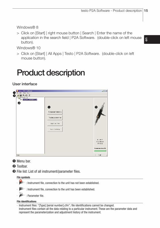
Windows® 8
> Click on [Start] | right mouse button | Search | Enter the name of theapplication in the search field | P2A Software. (double-click on left mousebutton).
Windows® 10
> Click on [Start] | All Apps | Testo | P2A Software. (double-click on leftmouse button).
Product descriptionUser interface
➊ Menu bar.➋ Toolbar.➌ File list: List of all instrument/parameter files.
File symbols
· : Instrument file, connection to the unit has not been established.
· : Instrument file, connection to the unit has been established.
· : Parameter file.
File identifications
· Instrument files: “[Type] [serial number].cfm”; file identifications cannot be changed.Instrument files contain all the data relating to a particular instrument. These are the parameter data andrepresent the parameterization and adjustment history of the instrument.
16 testo P2A Software - Using the product
· Parameter files: “[Type] [serial number] [date] [time].cfp”; file identifications can be changed.Parameter files only contain parameter data. These can be copied to another instrument or parameter file forthe same type of instrument so that several instruments have the same parameter settings.
➍ List of functions.➎ File information:
Information displayed
· Instrument files: Type, serial number, firmware version and connection status of the instrument.· Parameter file: Type, serial number and firmware version of instrument with which the parameter file was
created.· Connection status (instrument files only): “red” connection is active, “green” connection is inactive.
Using the product
➢ Establishing a connection with the device:
Several instruments can be connected to the PC and administered via theP2A software, but only one connection can ever be active at any one time.Non-wired instruments can also be connected to the P2A Software forparameterization/adjustment. The supply to the instruments is then effectedvia the USB interface.
1 Connect the USB/mini-DIN adapter to the external interface (mini-DIN) ofthe instrument.
2 Connect the USB connector of the adapter to the PC.- The instrument file for the instrument connected appears in the
instrument file/parameter file list.
➢ Selecting the instrument/parameter file, activating a connection with thedevice:
Click on the requisite instrument/parameter file. - The selected file is highlighted in colour.
- For instrument files only: if a connection with the instrument has beenestablished, this is automatically activated.
➢ Changing an instrument/parameter file:
✓ The required instrument/parameter file is selected.
1 Click on Change parameterization button.
2 Enter parameters in the corresponding fields.
3 Click on Apply to confirm entries.
4 To leave the parameterization screen, click on OK.

17
de
enfr
esit
pt
svnl
????
testo P2A Software - Using the product
➢ Saving the parameters in a parameter file:
The parameter data for the selected instrument/parameter file can be saved.
Only parameter data stored in the standard file can be loaded into aninstrument!
✓ The required instrument/parameter file is selected.
1 In the menu bar, click on File > Save as.
2 Select the storage location and enter the file name.
3 Click on Save to confirm entries.
➢ Opening a parameter file:
All parameter files stored in the standard directory path are automaticallydisplayed in the file list when the software is started. Parameter files stored inother directories can also be opened.
Only parameter data stored in the standard file can be loaded into aninstrument!
1 In the menu bar, click on File > Open.
2 Select the storage location and click on the requisite parameter file.
3 Click on Open to confirm entries.
➢ Copying the parameter data:
The parameter data for an instrument/parameter file can be transferred toanother instrument/parameter file for the same type of instrument. Historydata for instrument files are not transferred.
1 Select file from which the parameter data are to be copied.
2 In the menu bar, click on Edit > Copy.
3 Select the file which is to be modified.
4 In the menu bar, click on Edit > Paste.
➢ Analyzing/testing the instrument:
✓ The required instrument file is selected.
1 Click on Test / analyze transmitter button.
2 Perform tasks:
Options
· Carry out factory reset: Reset the parameter unit, scaling limits and adjustment to the factory settings(values device-specific, see type label).
· Transmitter tests: Manually switch switching outputs to test functionality.· Min./max. values: Change to display of minimum/maximum values.

18 testo P2A Software - Using the product
3 Click on Apply to confirm entries.
4 To leave the analyzing/test screen, click on OK.
➢ Carrying out a 1-point adjustment:
A 1-point adjustment (offset) can be performed. A dew point mirror isrecommended as a reference measuring instrument for dew pointtemperatures < 0 °Ctd.
1 Click on Adjust transmitter button.
2 Expose the reference measuring instrument and the instrument to beadjusted to the same constant conditions and wait for equalization periodto lapse.
3 Enter reference value and perform adjustment by clicking on Carry out 1-point adjustment.
To reset an offset value, click on Set Offset to zero.
4 Click on Apply to confirm entries.
➢ Viewing a transmitter history:
The current history data as stored in the instrument file are always displayed.A distinction is made between parameterization and adjustment histories.
Dates and times refer to the PC time when the P2A Software was beingused. History data are only stored in the instrument file (PC), not in the testo6721.
1 Click on Transmitter history button.
2 To move between the views, click on Parameterization history or Adjustmenthistory.
To print the history data, click on Print.
➢ Deleting parameters from an instrument/parameter file:
The parameter data for the selected instrument/parameter file can bedeleted.
✓ The required instrument/parameter file is selected.
1 Right-click on the instrument/parameter file.
2 Select Delete.
3 Click on Yes to confirm.

19
de
enfr
esit
pt
svnl
????
testo P2A Software - Tips and assistance
➢ Creating a new folder:
✓ The folder to which the new folder is to be added is selected.
1 In the menu bar, click on File > Add Folder.
2 Give the new folder a name.
Tips and assistance
Questions and answersQuestion Possible causes/solutions
Connection to instrument cannotbe established. · Check connecting cable and plug contacts.
· USB driver not/incorrectly installed: Re-install.Adjustment is to be reversed. · Carry out factory reset: Click on Test/ analyze transmitter > click
on Carry out factory reset.
If we could not answer your question, please contact your dealer or TestoCustomer Service. Contact details can be found on the guarantee card or onthe Internet at: www.testo.com

testo SE & Co. KGaA
Postfach 11 40, 79849 LenzkirchTesto-Straße 1, 79853 Lenzkirch
Telephone: +49 (0) 7653 681-0Fax: +49 (0) 7653 681-100
E-mail: [email protected]: http://www.testo.com
0970 6720 en 05
ww
w.t
esto
.co
m