instruction manual en - dr. fritz faulhaber gmbh & …€¦ · faulhaber motion manager 5.4...
TRANSCRIPT
WE CREATE MOTION
EN
PC-SoftwareFAULHABER Motion Manager 5.4
Instruction Manual

2
Version:5th issue, 14.10.2015Software status 5.4
Copyrightby Dr. Fritz Faulhaber GmbH & Co. KGDaimlerstr. 23 / 25 · 71101 Schönaich
All rights reserved, including those to the trans-lation.This description, whether in part or whole, may not be duplicated, reproduced, stored in an information system or processed or transferred in any other form without the explicit written consent of Dr. Fritz Faulhaber GmbH & Co. KG.
Parts of the product are subject to US American export regulations.
This instruction manual has been prepared with due care.However, Dr. Fritz Faulhaber GmbH & Co. KG does not accept any liability for possible errors in this instruction manual and their consequences. Equally, no liability is accepted for direct losses or consequential damages resulting from improper use of the devices.
The relevant regulations regarding safety en-gineering and interference suppression as well as the requirements specified in this instruction manual are to be noted and followed when using the software.
Subject to change without notice.
Imprint
3
1 Important Information 51.1 Symbols used in this instruction manual 5
1.2 Directions for use 6
2 Description 72.1 General product description 7
3 Installation 83.1 System requirements 8
3.2 Installing the software 8
3.3 Updating the software 9
3.4 Uninstalling the software 9
4 Basic Functions 104.1 Starting the software 10
4.1.1 Starting Motion Manager 5 via the Start menu 10
4.1.2 Starting Motion Manager 5 with command options 10
4.1.3 Automatic scan for connected devices 11
4.1.4 Setting up connections 12
4.2 The user interface 14
4.2.1 The Menu bar 14
4.2.2 The Quick Start bar 16
4.2.3 The command input field 17
4.2.4 The Node Explorer 18
4.2.5 The Input / Output area 19
4.2.6 The Status bar 20
4.3 The Wizards 21
4.3.1 The Connection Wizard 21
4.3.2 The Motor Wizard 22
4.3.3 The Configuration Wizard 24
4.3.4 The Controller Tuning Wizard (for Motion Controller only) 24
4.4 The Configuration dialogs 28
4.4.1 Configuring the Motion Controller 28
4.4.2 Configuring the Speed Controller 32
4.5 Options 32
Contents
4
Contents
5 Additional Functions 335.1 Sequential programs 33
5.2 Parameter files 36
5.3 Analysis 37
5.3.1 Status display 37
5.3.2 Graphic analysis function 37
5.4 Visual Basic Script programs 41
5.4.1 Creating the script program 41
5.4.2 Motion Manager functions 41
5.4.3 Starting the script program 47
5.4.4 Cancelling the script program 47
5.5 Macro functions 48
5.5.1 Defining macros 48
5.5.2 Running macros 49
5.6 CAN 49
5.6.1 Advanced Motion Manager commands 49
5.6.2 The CANopen object browser 52
5.6.3 PDO Mapping 53
6 Maintenance 546.1 Software update 54
6.2 Troubleshooting 54
7 Licence Agreement 55

5
1 Important Information
This instruction manual describes the installation, configuration and use of the Motion Manager 5 software from FAULHABER.
� Please read through the complete instruction manual before using the software.
� Keep this instruction manual in a safe place for later use.
� Motion Manager 5 is a 32 bit software for PCs with Microsoft® Windows® operating system.
� FAULHABER is not liable for any data loss, damage or other problems which arise due to use of this software.
1.1 Symbols used in this instruction manual
CAUTION! Caution!This pictogram with the wording "Caution!" indicates an imminent danger which can result in slight physical injuries or material damage.
f This arrow points out the appropriate precautions.
NOTENoteThis “Note” pictogram provides tips and recommendations for use and handling of the program.
6
1 Important Information
1.2 Directions for use
Compliance with the following directions for use is prerequisite for working with the FAULHABER Motion Manager 5. You should therefore carefully read through all instructions and follow them when using the software.
Intended useThe FAULHABER Motion Manager 5 is designed for the configuration and putting into service of FAULHABER drive controls. The software is not designed for activating drive systems in productive operation.
Depending on the models concerned, the controls to be configured can be connected to the PC via various interfaces. Depending on the control’s features a programming adapter may also be re-quired, which is available from FAULHABER on request.
NOTEAlways note and follow the parameterisation and commissioning information provided in the oper-ating instructions of the respective drive controls.
The Motion Manager 5 software is designed for the following tasks:
� Configuring the device functions and the drive parameters with the help of graphic dialogs
� Operating the devices via serial RS232, USB or CAN interface
� Command input with plain text support
� Creating, transferring and managing sequential programs and parameter files
� Dynamic setting of the controller parameters
� Graphic online analysis of the drive‘s performance
� Creating and executing simple program sequences with the help of VBScript
NOTEThe functions listed above are not available in all controls and depend on the features of the respec-tive control to be configured.
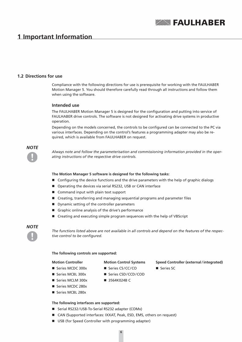
The following controls are supported:
Motion Controller
� Series MCDC 300x
� Series MCBL 300x
� Series MCLM 300x
� Series MCDC 280x
� Series MCBL 280x
Motion Control Systems
� Series CS / CC / CO
� Series CSD / CCD / COD
� 3564K024B C
Speed Controller (external / integrated)
� Series SC
The following interfaces are supported:
� Serial RS232 / USB-To-Serial RS232 adapter (COMx)
� CAN (Supported interfaces: IXXAT, Peak, ESD, EMS, others on request)
� USB (for Speed Controller with programming adapter)
7
2 Description
2.1 General product description
Motion Manager 5 software from FAULHABER provides convenient access to the settings and parameters of the connected motor controls.
The graphic user interface can be used to read out, change and reload configurations. Individual commands or complete parameter sets and program sequences can be entered and transferred to the control. Command responses are logged together with the sent commands in the “History” tab. In addition, analysis options are available in the form of status displays and graphic trace windows.
Communication with the motor control takes place either via a serial RS232, a USB or a CAN inter-face.
Starting the software
After the software has started the enabled interfaces are opened one after the other and the speci-fied address range is searched for connected devices (scanning process).
The program interface
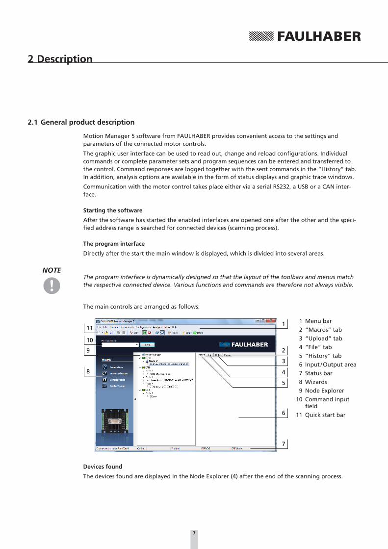
Directly after the start the main window is displayed, which is divided into several areas.
NOTEThe program interface is dynamically designed so that the layout of the toolbars and menus match the respective connected device. Various functions and commands are therefore not always visible.
The main controls are arranged as follows:
1
6
7
11
10
9
8
3
2
5
4
1 Menu bar
2 “Macros” tab
3 “Upload” tab
4 “File” tab
5 “History” tab
6 Input / Output area
7 Status bar
8 Wizards
9 Node Explorer
10 Command input field
11 Quick start bar
Devices found
The devices found are displayed in the Node Explorer (4) after the end of the scanning process.

8
3 Installation
3.1 System requirements
The Motion Manager 5 software from FAULHABER has been developed for PC systems with Microsoft® Windows® XP and higher operating systems installed.
Recommended minimum configuration of the PC system:
� Hard disk drive space required: 60 MB
3.2 Installing the software
The “SetupMoman5_*.exe” file is required to install Motion Manager 5.
� Run the “SetupMoman5_*.exe” file.
� Select the required language version (German or English).
� Confirm the Start window of the installation program by clicking “Next”.
� Read the complete End User licence agreement. If you agree to the terms of the licence agree-ment, tick the relevant selection box and confirm your selection by clicking “Next”.
� If necessary, change the installation path for the software and then click “Next”.
� Also, if necessary, adjust the name of the program link and the creation of additional links and then click “Next”.
� Use the summary displayed to check the settings made and start the installation by clicking “Install”.
� The installation process is carried out.
� Select whether the software is to be started after installation or not and end the installation by clicking “Finish”.

9
3 Installation
3.3 Updating the software
The updating of the installed software version differs depending on the predecessor version.
Updating Version 4.xx or older
An already existing Version 4.xx or older of Motion Manager is not impaired by the installation of Motion Manager 5. The two versions can exist alongside each other on the same PC system. In this case the installation process is as described in Chapter 3.2 “Installing the software”.
Updating Version 5.xx
If an older version of Motion Manager 5 exists on the system it is updated when a newer version is installed.
Use the “Options” menu item in the “Extras” menu to activate an automatic or manual online update function, in order to keep the software up to date at all times via an existing internet connection.
3.4 Uninstalling the software
To completely remove Motion Manager 5, complete the following steps:
� Open the “Programs and Features” or “Software” menu in the Windows Control Panel.
� Select “FAULHABER Motion Manager 5” from the list and click “Uninstall” or “Remove”.
� Confirm the renewed prompt whether Motion Manager 5 is to be removed or not.
10
4 Basic Functions
4.1 Starting the software
4.1.1 Starting Motion Manager 5 via the Start menu
Following installation the “ FAULHABER” group in the Start menu contains the “Motion Manager 5” link which can be used to start the software.
4.1.2 Starting Motion Manager 5 with command options
The program file Moman5.exe contains various command options which can be used when starting the software from the command line or adjusted link.
NOTEThe program file must be opened from the installation directory of the Motion Manager (working directory).
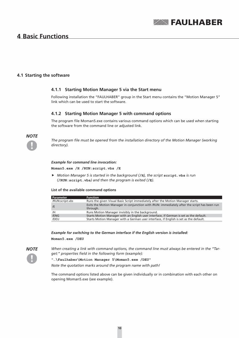
Example for command line invocation:
Moman5.exe /H /RUN:script.vbs /E
f Motion Manager 5 is started in the background (/H), the script script.vbs is run (/RUN:script.vbs) and then the program is exited (/E).
List of the available command options
Parameter Function/RUN:script.vbs Runs the given Visual Basic Script immediately after the Motion Manager starts.
/E Exits the Motion Manager in conjunction with /RUN: immediately after the script has been run through.
/H Runs Motion Manager invisibly in the background./ENG Starts Motion Manager with an English user interface, if German is set as the default./DEU Starts Motion Manager with a German user interface, if English is set as the default.
Example for switching to the German interface if the English version is installed:
Moman5.exe /DEU
NOTE When creating a link with command options, the command line must always be entered in the “Tar-get:” properties field in the following form (example):
"…\Faulhaber\Motion Manager 5\Moman5.exe /DEU"
Note the quotation marks around the program name with path!
The command options listed above can be given individually or in combination with each other on opening Moman5.exe (see example).

11
4 Basic Functions4.1 Starting the software
4.1.3 Automatic scan for connected devices
After starting the software, Motion Manager automatically searches the interfaces selected under “Connections...” (see Chapter 4.1.4 “Setting up connections”) for connected controls within the spec-ified address ranges (scanning area of the node No.). To this end the interface and protocol plug-ins selected for each interface are used.
Default connection parameters
Parameter FunctionPC interface COM1Scanning range 0 – 10Protocol Serial FAULHABER protocol for Motion Controller with RS232 interfaceInterface Standard serial interface
Following completion of the scan procedure, all detected controls are displayed in the Node Explorer.
If a control could not be detected, the Motion Manager automatically starts the Connection Wizard, with the help of which the required connection parameters can be set (see Chapter 4.3.1 “The Con-nection Wizard”).
NOTE The scanning process can also be invoked manually at any time after Motion Manager has been started.
f Menu bar - Terminal - Node Search
f Scan button on the Quick Start bar
f “F2” key
As an alternative to the Connection Wizard, the connection parameters for further interfaces can also be set under the menu item “Terminal - Connections …” (see Chapter 4.1.4 “Setting up connec-tions”).
Apart from the Connection Wizard, there are other useful Wizards for the start-up on the left-hand edge of the program window (see Chapter 4.3 “The Wizards”). From here the Connection Wizard can also be opened manually at any time.
NOTE Offline modeIf no control is connected and the serial interface is activated, an offline mode is available under the context menu of the Node Explorer (right-click). This enables the configuration interface of a previ-ously selected Controller variant to be displayed. In this way the setting options can be viewed even without connected hardware.
12
4 Basic Functions4.1 Starting the software
4.1.4 Setting up connections
The easiest way to set up a connection between the Motion Manager and the connected control is to use the Connection Wizard (see Chapter 4.3.1 “The Connection Wizard”).
If the connection from Motion Manager to the connected control is to be set up without the Con-nection Wizard, this can be done using the “Connections...” function in the “Terminal” menu of the Menu bar. Here, in addition to an already set connection, it is possible to activate other interfaces, which are then displayed one below the other in the Node Explorer.
Double-click the required node to activate the respective interface.
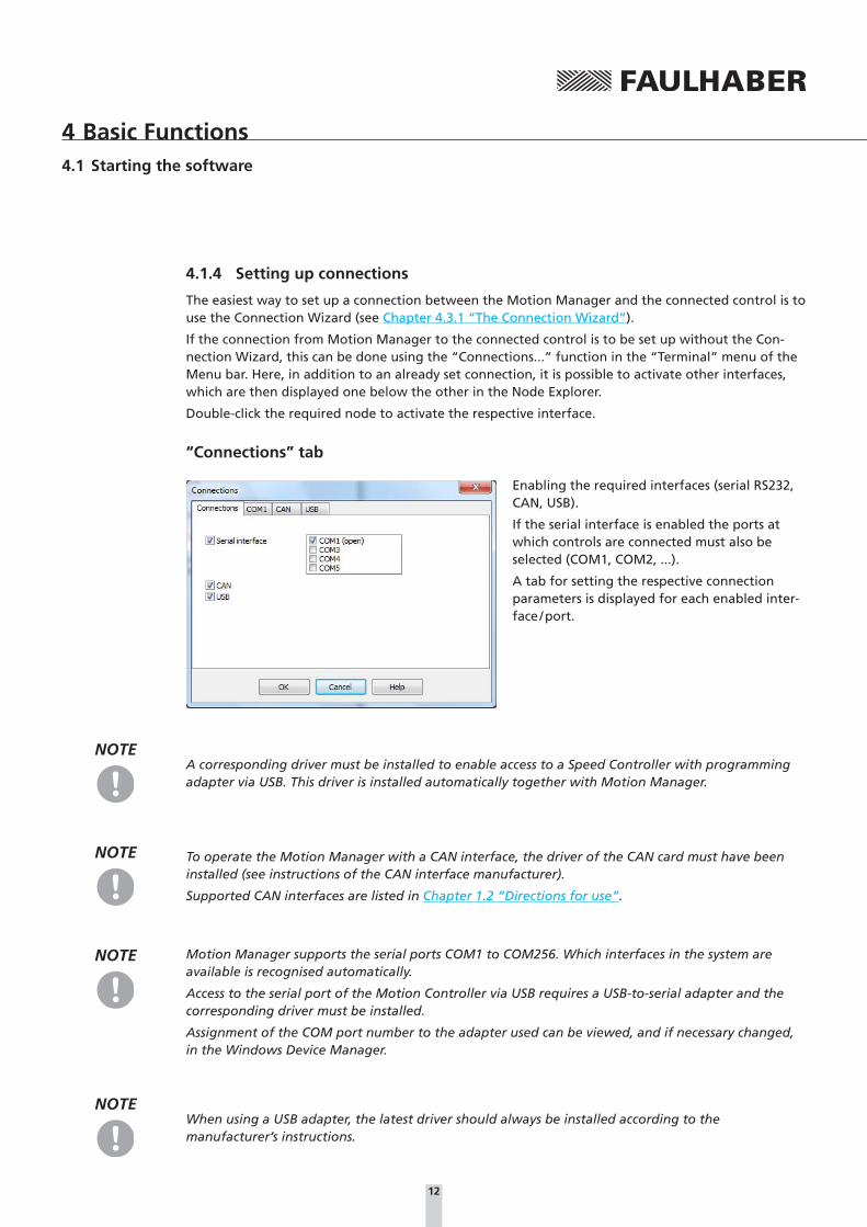
“Connections” tab
Enabling the required interfaces (serial RS232, CAN, USB).
If the serial interface is enabled the ports at which controls are connected must also be selected (COM1, COM2, ...).
A tab for setting the respective connection parameters is displayed for each enabled inter-face / port.
NOTEA corresponding driver must be installed to enable access to a Speed Controller with programming adapter via USB. This driver is installed automatically together with Motion Manager.
NOTE To operate the Motion Manager with a CAN interface, the driver of the CAN card must have been installed (see instructions of the CAN interface manufacturer).
Supported CAN interfaces are listed in Chapter 1.2 “Directions for use”.
NOTE Motion Manager supports the serial ports COM1 to COM256. Which interfaces in the system are available is recognised automatically.
Access to the serial port of the Motion Controller via USB requires a USB-to-serial adapter and the corresponding driver must be installed.
Assignment of the COM port number to the adapter used can be viewed, and if necessary changed, in the Windows Device Manager.
NOTEWhen using a USB adapter, the latest driver should always be installed according to the manufacturer’s instructions.

13
4 Basic Functions4.1 Starting the software
“COMx”, “CAN” and “USB” tabs
Connection settings for the respective interface.
Interface plug-in:
Select the DLL file which makes the connection between Motion Manager and the interface driver.
� COMx: Default “Mocom.dll”
� CAN: As a default, “Ixxat_vci3.dll” is in-stalled for IXXAT CAN interfaces via their VCI3 driver. A corresponding plug-in file is required for other manufacturers' interfaces or for other drivers (e.g. “ems_cpc.dll for EMS-Wuensche interfaces).
� USB: “SerialDL.dll”
Protocol plug-in:
Selection of the DLL file with the communication protocol of the devices to be addressed.
� COMx with Motion Controller: “Dffrsprot.dll”
� COMx with Speed Controller: “Dffscprot.dll”
� CAN with Motion Controller and CANopen / FAULHABER CAN protocol (e.g. CF series): “Dffcanprot.dll”
� CAN with Motion Controller and pure CANopen protocol (CO series): “Canopenprot.dll”
� USB with Speed Controller: “Usbscprot.dll”
NOTE It is also possible to use several protocols via one interface as long as no protocol conflicts occur. Then when scanning the network, all the given protocol plug-ins are loaded one after the other to search for supported nodes.
Baud rate:
Setting for the speed of the data transfer (transfer rate). Please check beforehand whether all de-vices to be addressed at this interface also support the required baud rate.
Scan range:
Setting the range of the node numbers in which connected devices are to be looked for (no signifi-cance for FAULHABER Speed Controllers).
Click “OK” to save the settings and automatically search through the selected interfaces. Any con-trols found are displayed in the Node Explorer.

14
4 Basic Functions
4.2 The user interface
The main window of the FAULHABER Motion Manager is divided into different areas (see Chapter 2.1 “General product description”), which are described in greater detail here.
4.2.1 The Menu bar
The menu bar contains all functions and commands required to use the Motion Manager. Its ap-pearance is dynamic and depends on the currently selected control so that several functions are only available if they are actually supported by the control.
“File” menuThe “File” menu contains the standard functions for creating, opening, saving and printing Motion Manager files.
The following file types can be processed with Motion Manager:
� Motion Control files *.mcl
� Motion Parameter files *.mcp
� Visual Basic Script files *.vbs
The “New” menu item deletes the input / output area of the displayed tab.
NOTEAll the file types given are text files. Therefore, program or parameter files, which have been saved with other file extensions, can also be opened.
“Edit” menuIn addition to the standard functions of the “Edit” menu, the “Program File” item can be used here to activate program editing mode for several controls.
If this menu item is activated, commands selected from the Commands menu are not sent directly to the drive, but are copied into the current in the “File” or “Macros” tab, where they can be used to create a sequential program or a macro.
NOTEThe program editing mode can also be activated by selecting “Motion Control File” in the pull-down menu of the “File-New” symbol.
“Terminal” menuAll settings and actions based on the connection with the control can be controlled in this menu. In addition, functions for transferring, receiving and comparing program and parameter files are avail-able for several controls.
Visual Basic Scripts and Macros loaded in Motion Manager can also be run using this.
15
4 Basic Functions4.2 The user interface
“Commands” menuThis menu is only available if a control with command interface has been selected (see Chapter 4.2.4 “The Node Explorer”). It contains the most important commands of the connected control. After selecting a command and possibly entering a value the command is copied into the command input field. From here the command can be sent directly to the control, whereby the node number of the selected device is automatically placed in front in network mode (see Chapter 4.2.3 “The command input field”). Touch the commands with the mouse and a precise explanation of them appears in the Status bar at the bottom edge of the Motion Manager window.
“CAN” menuThis menu is only available if a CAN node has been selected (see Chapter 4.2.4 “The Node Explorer”).
The “CAN” menu contains special functions for operating CAN controls, among other things the telegrams for controlling the CANopen state machines (NMT, Device Control) and for motion control, access to the CANopen object dictionary or node configuration via the LSS protocol. Any CAN tel-egrams can also be sent.
“Configuration” menuThe “Configuration” menu contains configuration dialogs for setting drive functions and param-eters. For example, the following settings can be made here:
� General basic settings such as operating mode, connected motor / encoder, etc.
� Drive parameters such as positioning range limits, speed ranges, etc.
� Controller parameters
� Function of the inputs / outputs and definition of a reference run
� Connection parameters of the control such as transfer rate and node No.
NOTEThe layout of the menus and the dialogs is dynamic and depends on the control to be configured.
“Analysis” menuMotion Manager provides the opportunity to display the status of the control (status display) and to visualise the control’s performance (Graphic Analysis), provided the selected device supports this function. See Chapter 5.3 “Analysis”.
“Extras” menuThe “Extras” menu contains additional functions such as
� Options for Motion Manager online updates and general settings, see Chapter 4.5 “Options”.
� Running firmware updates on Motion Controllers via the serial RS232 or CAN interface.
16
4 Basic Functions4.2 The user interface
“Help” menuThe “Help” menu contains the reference to this instruction manual, options for contacting FAULHABER via its homepage and by eMail and a reference to the Help file of Visual Basic Script.
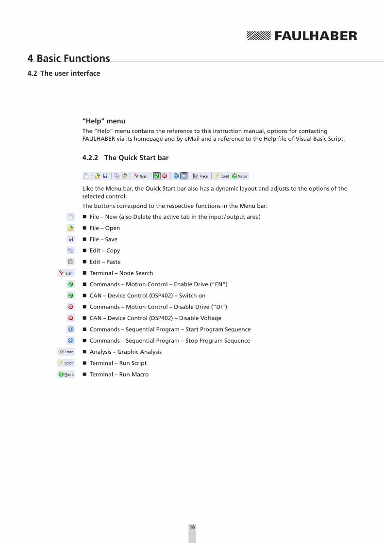
4.2.2 The Quick Start bar
Like the Menu bar, the Quick Start bar also has a dynamic layout and adjusts to the options of the selected control.
The buttons correspond to the respective functions in the Menu bar:
� File – New (also Delete the active tab in the input / output area)
� File – Open
� File – Save
� Edit – Copy
� Edit – Paste
� Terminal – Node Search
� Commands – Motion Control – Enable Drive (“EN”)
� CAN – Device Control (DSP402) – Switch on
� Commands – Motion Control – Disable Drive (“DI”)
� CAN – Device Control (DSP402) – Disable Voltage
� Commands – Sequential Program – Start Program Sequence
� Commands – Sequential Program – Stop Program Sequence
� Analysis – Graphic Analysis
� Terminal – Run Script
� Terminal – Run Macro

17
4 Basic Functions4.2 The user interface
4.2.3 The command input field
The command input field enables the manual input of commands. If the selected control has a com-mand interface, depending on the “Program File” setting, the entered command can then be sent directly to the control, or it can be copied into the “File” or “Macro”editor window.
In the case of controls with serial command interface the entered text is sent unchanged to the ac-tive COM port, irrespective of which serial node is selected. In the case of CAN devices the entered command is translated into a corresponding CAN telegram in accordance with the set CAN protocol with identifier according to the Node No. of the selected device. The CAN telegram is forwarded via the set interface plug-in to the driver of the CAN interface card.
The commands can either be entered in the input field manually, or can be selected from the list of available commands in the “Commands” menu. If applicable, following a parameter query, the selected command is copied into the input field together with the entered value.
The possible commands can be looked up in the command reference of the respective Motion Con-troller and in Chapter 5.6 “CAN”.
Program file
Enable the “Program File” function in the “Edit” menu to change the button next to the input field from “Send” to “Apply”. Motion Manager then does not send the commands in the input field to the controller but to the Editor window of the “File” or “Macros” tab in the input / output area.
NOTE When you switchover tabs in the input / output area the “Program File” function is automatically disabled. Commands entered in the input field are once again sent to the control.
The Debug toolbar is retained until the file editing area is deleted using “File” - “New”, or you switch to another node.

18
4 Basic Functions4.2 The user interface
4.2.4 The Node Explorer
The Node Explorer displays all the controls found with which Motion Manager was able to success-fully set up a connection. The display is divided into three hierarchies:
� Interface (COMx / CAN / USB)
� Node No.
� Drive and control
NOTEIf the interface symbol is crossed out in the Node Explorer display the set interface is not available (e.g. blocked by another application, not available or an incorrect CAN driver has been set).
Selecting a control
The control whose settings are to be edited is selected by double-clicking the corresponding node. The active node is displayed in bold and with a network symbol.
Tool Tip
If you move the mouse cursor in the Node Explorer window a Tool Tip box appears briefly with fur-ther info on the selected node and the set interface parameters.
The Context menu
Click the right-hand mouse button (“right-click”) on the window of the Node Explorer and a Con-text menu appears for controls with command interface; this Context menu makes various functions available depending on the control selected.
For example:
� Display info about the selected node, e.g. Firmware version and Serial No. (Node Info)
� CAN functions according to CAN menu
NOTE The Speed Controllers cannot respond to Scan Commands. Therefore the corresponding node appears in the Node Explorer permanently, if this control type is set, irrespective of the presence of a connected control or not.

19
4 Basic Functions4.2 The user interface
4.2.5 The Input / Output area
The input / output area is divided into four tabs, each of which contains a Text Editor window.
History
All commands sent and all data received is displayed in the “History” tab of the input/output area. Received data is shown in italics. The corresponding CAN telegrams are displayed for CAN commands (not for FAULHABER commands which are transferred via the FAULHABER channel).
File
The “File” tab can be used to write your own program files or scripts. Files created here can be sent to the control (sequential programs) or can be executed on the PC (VBScripts) and stored locally on the PC. Files loaded via the “File” – “Open” command also appear in this tab. In this case the tab name changes to the file name.
The syntax highlighting is adjusted to the loaded file type automatically, but can also be changed manually using the toolbar.
If syntax highlighting is activated, an optional bar with code templates can be displayed. The code blocks can be added to the program code by Drag&Drop. Vice-versa, a selected code area from the Editor window can be dragged into the bar with code blocks, thereby creating a new block. New blocks that are added can be removed again using the “Delete” key.
If MCL format is activated another toolbar is displayed in this tab for debugging sequential pro-grams.

20
4 Basic Functions4.2 The user interface
Upload
If data records are loaded from the control onto the PC (parameter or program files), the data ap-pears in the “Upload” tab. The data can be edited and saved in the Upload window and transferred back to the control.
Macros
The “Macros” tab is used for editing and managing macros. These are short command sequences, which can be sent to the control (see Chapter 5.5 “Macro functions”).
NOTEThe content of each Editor window in the input / output area can be saved, printed out and deleted (“File” – “New”).
4.2.6 The Status bar
The status bar displays the current status of Motion Manager and the selected control. In normal status, if none of the buttons are touched with the mouse cursor, the display is divided up as follows:
� Currently selected nodes and interface or program editing mode
� Status of the connection
� CANopen NMT status
� Status of the control
� Currently set mode of the control
NOTE Apart from the layout in normal status the status bar also displays useful information on many but-tons or commands, if they are touched with the mouse cursor.
Example: Display if the “Commands” – “Sequential Program” – “TIMEOUT” command is touched

21
4 Basic Functions
4.3 The Wizards
At the left-hand edge of the main window there is an area with buttons, with which the various Wizards can be opened for fast start-up of a connected drive unit.
The "Connections" button is always displayed, the other buttons are only displayed if a connection with a drive unit already exists and the respective function is supported by its controller.
The Wizards are arranged in the order in which they are normally used. It is therefore advisable to work through them in order:
After a connection has been set up with the required drive unit, for ex-ternal controllers, the connected motor should be selected first and the determined parameters transferred. Other settings can be made with the help of the configuration dialog in order to adjust the controller to the required application.
After these settings have all been made the Controller Tuning Wizard can be used to optimise the controller parameters and to observe the transient response.
4.3.1 The Connection Wizard
The Connection Wizard appears automatically if no connected node is found when the Motion Manager is started. Alternatively, it can be opened at any time using the "Connection" button in the Wizard bar.
This Wizard assists the user while setting up the connection with the connected control.
The Connection Wizard is roughly divided into 3 steps:
Step 1: Select the device family
� Motion Controller with RS232 interface
� Motion Controller with CAN interface
� Speed Controller
Step 2: Setting the connection parameters
Depending on the device family set, the corresponding connection parameters are queried here (interface used, transfer rate,…).
With CAN devices it is also possible here to appropriately configure connected devices, which are not yet set on a valid node number.
Step 3: Summary and completion
The settings made are displayed in a summary for final checking.
You can correct incorrect settings by clicking the “Back” key. The connection set-up is finished with the “Finish” key.
Following completion the node found appears in the Node Explorer.

22
4 Basic Functions4.3 The Wizards
4.3.2 The Motor Wizard
The Motor Wizard can be opened using the “Motor Selection” button in the Wizard bar.
This Wizard enables an external control to be adjusted to the connected motor by selecting the respective FAULHABER motor from a list.
Motor data and current limiting values as well as additionally calculated controller parameters are set for the selected motor. This function can also be used for integrated units.
The Motor Wizard is divided into 5 sections and is adapted dynamically to the chosen configuration. It is possible that not all the listed setting options are available for the control concerned.
1. Motor selection
The FAULHABER catalogue motors, of the motor types supported by the control selected in the Node Explorer, are available to choose from.
The top listbox contains the motor types supported by the con-trol. The two listboxes below it contain the product identifica-tion given in the motor labelling.
Motors that are not included in the list can be added to the list using the “Create” button. To do this, it is necessary to manually enter the motor’s data sheet values.
In addition to the motor the sensor type used (Hall sensors, incremental encoders, etc.) must also be selected. Here too a selection of sensor types matching the control is available to choose from.
NOTE In the case of Speed Controllers, it is not possible to check which motor and sensor types are sup-ported by the connected control, therefore, all possible configurations are displayed here to choose from.
The applied motor voltage (voltage value set at the power pack for the motor supply) is either read out from the control automatically (Motion Controller), or it has to be entered manually (Speed Con-troller). This value does not necessarily have to be the same as the nominal voltage of the motor.
CAUTION! Power supply!Material damage can occur if the voltage applied is too high or an incorrect voltage value is entered.
f The allowable voltage ranges of the respective control must be adhered to (see data sheet of the control).

23
4 Basic Functions4.3 The Wizards
2. Load transmission
In this section various types of load transmission are available (gearing, spindle, …). The settings made also affect the design of the controller in this control.
3. Inertia factor
Details of the coupled load are also required to calculate the controller parameters. To this end, a sliding controller is available for the inertia factor KJ , which is calculated from the mass moment of inertia of the motor JMot and the load Jload.
KJ=Jload+ JMot
JMot
The moment of inertia of the motor JMot is known from the data sheet values and equals the rotor inertia torque. The moment of inertia of the load Jload must be estimated or determined; if the value is known it can also be entered directly in the relevant field.
NOTEThe inertia factor is limited to 30 for calculation of the controller parameters.
4. Controller setting
Another preset for the calculation of the controller parameters is the information whether the con-troller is to be optimised for smooth running or high dynamic.
Under certain circumstances, after pressing the “Next” button a prompt also appears asking for the required operating speed.
5. Overview
The final Wizard page shows a summary of the controller parameters determined for the selected motor / sensor combination.
You can correct incorrect settings by clicking the “Back” button. Press the “Finished” button to trans-fer the motor data and the determined controller parameters to the control.
Speed Controller
Speed Controller data cannot be sent directly; here it is used to preassign new settings in the con-figuration dialog. The “Send” button must be pressed in the configuration dialog that then opens to transfer the new data to the control.
Motion Controller
The data for Motion Controllers is sent directly by relevant commands. If the parameters are to be retained after the control is switched on again, a SAVE command must then be run; this is prompted by a corresponding message.
After connecting a new brushless motor with analog Hall sensors to a Motion Controller and after transferring the motor and controller parameters, the Hall sensor signals should also be adjusted. To do this, press the “Configuration” button to start the configuration dialog. In the “Basic Settings” tab, press the “Optimisation to connected motor” button to perform the adjustment (see Chapter 4.4 “The Configuration Dialogs”).

24
4 Basic Functions4.3 The Wizards
4.3.3 The Configuration Wizard
The Configuration Wizard can be opened using the “Configuration” button in the Wizard bar or using the “Configuration – Drive functions…” menu item.
This Wizard enables further adjustments of the control to the required application.
After opening the Configuration Wizard the configuration dialog of the respective control ap-pears, with which detailed settings can be made for the various areas (basic settings, parameters, inputs / outputs, etc.) (see Chapter 4.4 “The Configuration dialogs”).
4.3.4 The Controller Tuning Wizard (for Motion Controller only)
The Controller Tuning Wizard can be opened using the “Controller Tuning” button in the Wizard bar.
This Wizard provides functions for recording and evaluating jump (step) responses by way of graphic analysis, and also enables manual optimisation of the controller parameters.
NOTEMotion Controllers with CAN interface must be in the NMT “Operational” state in order to open the graphic analysis.
The buttons in the toolbar enable the drive to be activated and deactivated (Enable / Disable the out-put stage) and the time intervals for the jump sequences can be set, as well as the size of the target corridor.
CAUTION! Uncontrolled movement!When performing jump sequences, the drive moves according to the entered values.
f Ensure that the drive can move freely within the range of the entered values while the jump sequences are being performed!
The following steps must be completed for optimisation of the controller parameters. For position-ing tasks, it is advisable to optimise the speed controller first and then the position controller.
NOTE For CO series Motion Controllers the TxPDO4 object is required to record the analysis data, which is reconfigured temporarily for this purpose. On closing the Wizard the original mapping of the TxPDO4 object is reset.
25
4 Basic Functions4.3 The Wizards
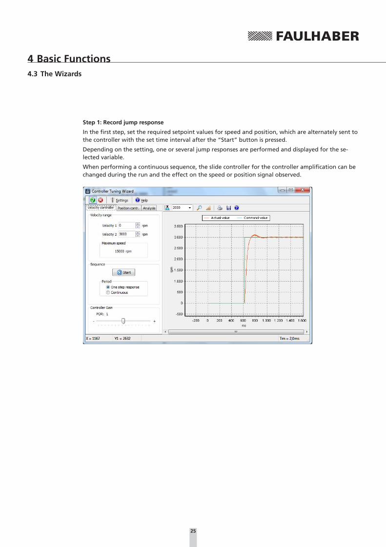
Step 1: Record jump response
In the first step, set the required setpoint values for speed and position, which are alternately sent to the controller with the set time interval after the “Start” button is pressed.
Depending on the setting, one or several jump responses are performed and displayed for the se-lected variable.
When performing a continuous sequence, the slide controller for the controller amplification can be changed during the run and the effect on the speed or position signal observed.

26
4 Basic Functions4.3 The Wizards
Step 2: Evaluate jump response
After at least one complete jump response has been recorded, it can be evaluated using the “Analy-sis” tab. If several jumps took place within a sequence (continuously), the last jump response is displayed.
The “Page” arrow keys can be used to switch between analysed jump responses to compare the re-sults with each other. The “Recycle Bin” deletes the displayed analysis result from the list of the jump responses.
Rise time: Period between the exit from the start corridor and the first entry into the target corridor.
Settling time: Period between the exit from the start corridor and the last entry into the target corridor.
Overshoot: Maximum difference between the actual value and the setpoint value.

27
4 Basic Functions4.3 The Wizards
Step 3: Optimise controller parameters
If further optimisation of the drive performance is required, the slide controller in the “Speed Con-troller” or “Position Controller” tab can be used to adjust the amplification of the respective control-ler and start a renewed sequence.
The last jump response of the new recorded sequence can be evaluated again using the “Analysis” tab and compared with the previously recorded jump responses.
Before the optimisation After the optimisation
As can be seen by the reduced control settling time and the reduced overshoot in the example shown here, following optimisation of the speed control gain to value 5 the drive has a significantly more dynamic performance.
Use the “Apply” button to set this setting in the drive again and after confirmation of the confirma-tion prompt can also be permanently saved.
NOTE f Use the Motor Wizards for the basic setting of the controller.
f For positioning tasks it is advisable to set the speed controller to be as dynamic as possible first, i.e. with low overshoot and short rise and settling time, and only then to optimise the position controller.
f Not all the controller parameters can be set using the Controller Tuning Wizard. For advanced settings, use the “Controller Parameters” form under the “Configuration – Controller Parameters” menu item. This form can also be used together with the trace window for the graphic analysis, in order to observe the effect of changes on the controller performance (see Chapter 5.3.2 “Graphic analysis function”).
28
4 Basic Functions
4.4 The Configuration dialogs
Extensive graphic configuration dialogs are available for each device group, which enable conveni-ent drive configuration and parameter assignment (“Configuration” menu or “Configuration” but-ton).
The configuration dialogs are usually divided into several pages. Changes can be made directly on the graphic interface and transferred to the drive unit by pressing the “Send” button.
NOTEThe parameter settings possible for each configuration and the function of the individual parameters are described in the relevant chapter of the device’s operating instructions.
4.4.1 Configuring the Motion Controller
The commands of the changed settings are transferred. The new setting is active immediately and is retained until the power supply to the control is switched off.
If the new setting is to be permanently saved, the “EEPSAV” or “SAVEAPP” button must then be pressed; this causes the current parameters to be transferred into the non-volatile memory of the drive unit.
Motion Controller with RS232 interfaceIn the case of Motion Controllers with RS232 interface the parameter commands of the changed set-tings are sent directly.
NOTEIf a sequential program is running in the control which independently sends data to the serial inter-face, it must be stopped before opening the configuration dialog to avoid incorrect display values!
Motion Controller with CAN interface CF seriesIn the case of Motion Controllers with CAN interface, CF series or older, the parameter commands of the changed settings are sent via the FAULHABER channel on PDO2. Please note that the configura-tion dialogs are not accessible until the “Operational” state. The drive unit must be placed in the appropriate state beforehand using the CAN NMT menu (Start Remote Node). The “Basic Settings” tab is available here in FAULHABER mode (OPMOD-1) only, as FAULHABER-specific configuration set-tings can be made here, which are not supported by the CANopen standard.
NOTE The “Basic Settings” tab also contains the “Optimisation to connected motor” function for BL and LM controllers. Change from another mode to FAULHABER-Mode (OPMOD-1 in the “Mode” tab) first to perform the optimisation (see “Optimisation to connected motor (MCBL / MCLM)” section in this chapter).
Motion Controller with CAN interface, CO seriesMotion Controllers with CAN interface, CO series are parameterised via the CANopen object diction-ary. Changed parameters are sent by means of SDO communication.
29
4 Basic Functions4.4 The Configuration dialogs
Optimisation to connected motor (MCBL / MCLM)If a new BL or linear motor has been connected to the controller, where possible the Hall sensor signals should be adjusted after the new motor parameters have been set (see Chapter 4.3.2 “The Motor Wizard”). A corresponding button is available for this in the “Basic Settings” tab of the con-figuration dialog.
Non-optimised Hall sensor signals can result in irregular motor running during the first few seconds after switching on and in less accuracy.
For improved adjustment of an MCBL Controller to the connected motor it is possible to additionally optimise the phase angle of the sinus commutation.
A non-optimised phase angle results in increased power consumption and as a result to a poorer ef-ficiency.
NOTEFor both optimisations it is necessary to ensure that the motor can move freely and without load for several seconds!
After pressing the “Optimization for connected motor” button you are guided through automatic optimisation of the Hall sensor signals and the phase angle.
After the optimisation has finished the determined system parameters must be saved permanently in the control using the SAVE command.
If you cannot run the connected motor with maximum velocity in no load because, for example, a gear is flange-mounted, it is possible that the automatic setting of the phase angle cannot be used.
For this case it is possible to correct the phase angle manually:
First, set the required output voltage on the relevant page. The setting can be made most accurately at 100% (corresponds to 15 000 rpm or no load speed of the drive). With certain connected drive units it is however advisable to reduce the value, e.g. so that a maximum gear input speed is not exceeded.
In this case, move the slide controller for the phase angle in one direction or the other and observe the current value. The phase angle is optimally set at the point where the smallest current value is displayed.
After successfully setting this page manually, quit it with “Next”. The Hall sensor signals may then be adjusted again. Finally, run another SAVE command to save the determined system parameters in the control permanently.

30
4 Basic Functions4.4 The Configuration dialogs
Dynamic setting of the controller parametersApart from the options provided by the Motor Wizard and the Controller Tuning Wizard (see Chap-ter 4.3 “The Wizards”), a separate dialog is available for setting the controller parameters. Under the menu item “Configuration” - “Controller Parameters...” the controller parameters can be changed online using the arrows of the input fields or by entering a value via the keyboard. As soon as the value of an input field has changed it is automatically sent to the drive. With keyboard entries the corresponding field remains grey until the field is quit or “Enter” has been pressed; only then is the value sent to the drive.
This enables dynamic synchronisation of the parameters, similar to the case with a potentiometer.
The controller parameter dialog is a non-modal dialog, which can also be opened alongside other windows, unlike the other configuration dialogs, which remain in the foreground until they are closed. In this way, e.g., while a graphic analysis is displayed, it is possible to turn the controller pa-rameters and observe the effect on speed or position stability.
After setting the optimum controller parameters do not forget “SAVE” or “EEPSAV” so that the parameters are retained even after the control is switched on again!
See also the “Setting the Controller Parameters” chapter in the Motion Controller Instruction Manual.
Configuring the connection parametersThe menu item “Configuration” - “Connection Parameters...” can be used to set the transfer rate and node No. of a connected drive unit.
Motion Controller with RS232 interface
If a connection with the Motion Controller exists, on the one hand a new node No. can be issued here for the network operation and on the other the transfer rate of the controller or the entire network can be changed.
After changing the transfer rate the transfer rate used by the Motion Manager is also changed ac-cordingly.
NOTEFor operation in a network it is important that none of the node addresses are assigned more than once and that all nodes operate with the same transfer rate!
To permanently save the connection parameters, “EEPSAV” must also be run here; if the network transfer rate is changed, “EEPSAV” must be individually sent for each node number!

31
4 Basic Functions4.4 The Configuration dialogs
Motion Controller with CAN interface
Transfer rates and the node address for the CANopen drives of FAULHABER are set here in accord-ance with the LSS protocol (Layer Setting Services and Protocol) according to CiA DSP305 V1.
This protocol offers two configuration options:
a.) Switch Mode Global:
All connected LSS slaves are placed in configuration mode. The baud rate and node ID (node ad-dress) can only be set if one LSS slave only is connected.
b.) Switch Mode Selective:
Precisely one LSS slave, whose Vendor ID, product code and serial No. are known, is placed in con-figuration mode. This mode can be used to configure individual drives in the network via their serial No.
An additional dialog is available for selecting the LSS mode, via which either an individual node can be configured globally or a node whose LSS data (vendor ID, product code and serial No.) are given in the following, can be configured selectively.
If an already configured node selected via the Node Explorer is to be reconfigured (e.g. other node No.), its LSS data is displayed directly so that the details then only have to be confirmed with “OK”.
If an unconfigured node (Node ID = 0xFF) is to be configured in the network, the vendor ID and the product code are already filled, the serial No. of the required node still has to be entered. If only one drive is connected, Global mode can be selected, for which no other data must be entered.
NOTE It must be noted that a connection with the Motion Controller can only be made if it is either set to AutoBaud or it is set to the same baud rate as the Motion Manager. For this reason the current setting should always be properly documented so that the stored transfer rate does not have to be determined at a later time by trial and error!
Apart from the vendor ID, the product code and the serial No., the LSS protocol also requires a revi-sion number. But this number is not used by FAULHABER Motion Controllers in the LSS protocol, therefore Motion Manager always transfers “0.0” here and the user does not have to make any entries!
After a connection has been set up with the required node you can change the transfer rate (fixed transfer rate or AutoBaud) and the node No.
After sending a new configuration it is saved in Motion Controller, which then performs a reset. The Motion Manager then uses the set or new transfer rate to scan the network again and the new con-figured drive nodes should now be correctly displayed in the Node Explorer.
NOTE In the case of Motion Controllers, CO series, please note that if changes are made to the node num-ber using the LSS dialog all COB-Ids are reset (depending on the node number) in accordance with the Predefined Connection Set and the transmission type of the PDOs is reset to the as delivered state.

32
4 Basic Functions4.4 The Configuration dialogs
4.4.2 Configuring the Speed Controller
In the case of the Speed Controllers the configuration change is made via a firmware download.
To check the effect of the change immediately, after downloading the “Run” button can be pressed, which switches the drive unit from configuration mode to operating mode. No configuration chang-es are possible in operating mode. To make new changes the “Stop” button must be pressed, which switches the drive unit back into configuration mode.
The control can only be switched to configuration mode after the power supply has been switched on. If the connection is interrupted during the configuration, use “Run” / “Stop” to switch back to configuration mode.
If the configuration dialog is quit, the drive unit is also placed in operating mode and immediately starts with the set configuration. If the drive is not to be started immediately the power supply must be switched off first.
4.5 OptionsThe general settings of the Motion Manager are located under the “Extras”- “Options” menu item.
They include the following points:
a.) General
• Options for online updates of the Motion Manager software
b.) Data exchange
• Passive mode
• Message filter (CAN only)
� The Motion Manager has a message filter with which CAN telegrams of inactive nodes can be filtered out. By default, in addition to heartbeat telegrams, all messages of inactive nodes are displayed in the “History” tab.
The default behaviour can be changed if necessary by ac-tivating the “Hide all” checkbox. However, exceptions can also be added and used. In this case, CAN telegrams with the given COB-ID are not filtered out.
33
5 Additional Functions
5.1 Sequential programs
Functions are available for editing, transferring, debugging and managing sequential programs for Motion Controllers which support the saving and running of sequential programs.
Loading an existing program sequence
Existing program sequences can be loaded in the File Editor window via “File” – “Open...”.
File format
The Motion Controller files have the default extension *.mcl. However, files created with any text editor can also be read in as the mcl files are saved in ASCII format.
Creating a sequential program
To create a new sequential program from the Context menu of the “File - New” button, select the “Motion Control File” item in the Quick Launch bar. Alternatively, the Motion Control file format (MCL) can also be activated in the “File” tab.
The code can now be entered. If program editing mode is enabled (“Edit” – “Program File” menu), which can be recognised by information in the status bar on the bottom left-hand side or by the tick in front of the menu item “Edit” – “Program File”, the commands from the “Commands” menu can be copied directly into the program code (“Send” button changes to “Apply”). As additional help, code examples can also be displayed using the toolbar of the Editor window (see Chapter 4.2.5 “The Input / Output area”).
A separate toolbar is available in the “File” tab for transferring, running and debugging sequential programs.
Syntax explanation
� Each line contains a command, some followed by a number as an argument (e.g.: LA1000).
� Spaces at the beginning and between the command and argument are ignored. Alphanumeric characters only are sent.
� In addition to the commands, comments can also be entered. Comments are introduced by a semicolon (;) and can be positioned at the end of a command line or in a separate line (e.g.: HO ;Define Home Position).
� Comments are not sent to the drive, they are only used to document the program stored in the PC.
� Each letter and each number in a line of the program is sent to the Motion Controller up to the appearance of a semi-colon. The Motion Controller saves the program line, provided it is a valid command.
� The “PROGSEQ” and “END” commands do not have to be entered as they are automatically sent by the “Transfer program file” function.
To quit program editing mode, select the menu item “Edit” – “Program File” again or switch to the “History” tab. Commands can now be sent directly to the drive again (“Apply” button changes back into “Send”).
34
5 Additional Functions5.1 Sequential programs
Transfer sequential program to the control
The entered or loaded program can be sent to the control by using the menu item “Terminal” – “Transfer File...” and then selecting “Sequential Program”.
If the Debug toolbar is displayed the sequential program can also be transferred using the Start but-ton which also starts the program immediately.
Compare sequential programs
By using the menu item “Terminal” – “Compare Files” and then selecting “Sequential Program” it is possible to check the program code of the File Editor window with the program code stored in the control to see whether they are the same or not.
If the sequential program is transferred using the Debug toolbar, the program is automatically com-pared with subsequent syntax error display before the program is started.
Load sequential program from the control into Motion Manager
A sequential program stored in the control can be transferred to the Motion Manager using the menu item “Terminal” – “Receive File” and by then selecting “Sequential Program”. The program code is then displayed in the “Upload” editor window and from here it can be edited, saved, printed out and also transferred again.
Start sequential program
After the program has been sent to the control it can be started via the “ENPROG” command or by clicking the “Start Program Sequence” button (see Chapter 4.2.2 “The Quick Start bar”).
If the sequential program is transferred using the Debug toolbar the program starts automatically.
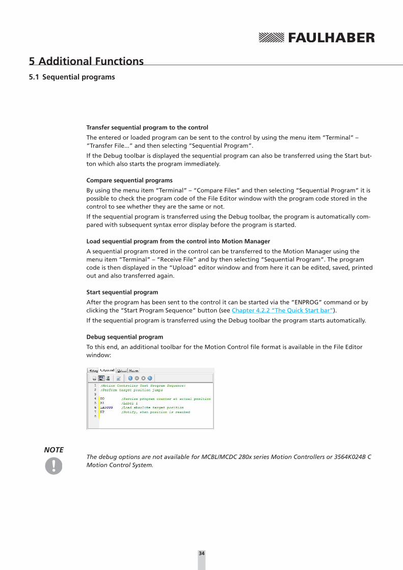
Debug sequential program
To this end, an additional toolbar for the Motion Control file format is available in the File Editor window:
NOTEThe debug options are not available for MCBL/MCDC 280x series Motion Controllers or 3564K024B C Motion Control System.

35
5 Additional Functions5.1 Sequential programs
� Transfer and execute sequential program
After the transfer the sequential program is first read back again and checked that it is the same. If there are any syntax errors, the command line entered cannot be interpreted by the Motion Controller and the faulty program line is then displayed in the Editor window in red. Following er-ror free transfer of the program the whole File Editor window is displayed grey. In this status the program runs on the controller and debug mode is enabled.
� Hold sequential program
If the program is running in debug mode, this button can be used to interrupt the running pro-gram. The current program line is then displayed in green in the Editor window.
� Stop sequential program
If the program is running in debug mode, this button can be used to quit the program and the debug mode. The File Editor window switches back to Edit mode and changes can once again be made to the program code.
� Single step
The displayed sequential program is transferred to the Motion Controller and is compared. Fol-lowing error free transfer of the program the whole File Editor window is displayed in grey and the first program line is displayed in green. The sequential program is now in the displayed pro-gram line and can be moved forward by one program step each time the button is pressed.
NOTEExamples of sequential programs are provided in the installation directory under \Motion Manager 5\Examples.

36
5 Additional Functions
5.2 Parameter files
In addition to the file functions for sequential programs, there are also functions for transferring, receiving and comparing parameter files and for the complete configuration of parameter file and sequential program.
Loading an existing parameter file
Existing parameter files (with and without sequential program) can be loaded in the File Editor win-dow via “File” – “Open...”.
File format
The Motion Controller parameter files are text files and have the default extension *.mcp.
Transfer parameter file
A loaded parameter set can be sent to the control using the menu item “Terminal” – “Transfer Pa-rameter File” or “Terminal” – “Transfer File...” and by then selecting “Parameter File”.
If a configuration file is loaded with program sequence and parameter listing, this can be transferred by selecting “Parameter File with Sequential Program”.
Receive parameter file
By using the menu item “Terminal” – “Receive Parameter File” or “Terminal” – “Receive File...” and then selecting “Parameter File” or “Parameter File with Sequential Program” it is possible to create an image of the drive configuration stored in the control.
The parameter configuration read in (with and without sequential program) is then displayed in the Upload Editor window, from where it can be edited, saved, printed out and transferred again.
Compare parameter file
By using the menu item “Terminal” – “Compare Parameter File” or “Terminal” – “Compare File...” and then selecting “Parameter File” or “Parameter File with Sequential Program” it is possible to check whether the loaded configuration file is the same as the control’s current configuration.
Edit parameter file
Before saving, comments can be added to parameter files for documentation purposes, as described in Chapter 5.1 under “Syntax explanation”.

37
5 Additional Functions
5.3 Analysis
Under the “Analysis” menu the Motion Manager provides two options for displaying the current status of the control and connected motor.
5.3.1 Status display
The status display can be started via the “Analysis” – “Status Display” menu, provided the selected control supports this function.
Changes to the listed values are identified by showing and hiding the tick in front of the value names. The display is updated every 500 ms
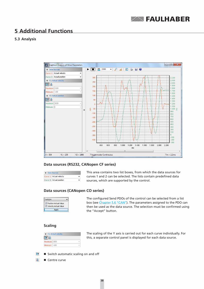
5.3.2 Graphic analysis function
The graphic analysis function of Motion Manager (Trace) provides numerous options for monitoring and evaluating the performance of the drive, provided the selected control supports this function. One possible application is the assessment of the dynamic performance of the motor and control or optimising the controller parameters (inclusion of step responses).
The analysis is started via the “Analysis” – “Graphic Analysis” menu or the corresponding button in the Quick Start bar (see Chapter 4.2.2 “The Quick Start bar”).
NOTEMotion Controllers with CAN interface must be in the NMT “Operational” state in order to open the graphic analysis.
38
5 Additional Functions5.3 Analysis
Data sources (RS232, CANopen CF series)
This area contains two list boxes, from which the data sources for curves 1 and 2 can be selected. The lists contain predefined data sources, which are supported by the control.
Data sources (CANopen CO series)
The configured Send PDOs of the control can be selected from a list box (see Chapter 5.6 “CAN”). The parameters assigned to the PDO can then be used as the data source. The selection must be confirmed using the “Accept” button.
Scaling
The scaling of the Y axis is carried out for each curve individually. For this, a separate control panel is displayed for each data source.
� Switch automatic scaling on and off
� Centre curve
39
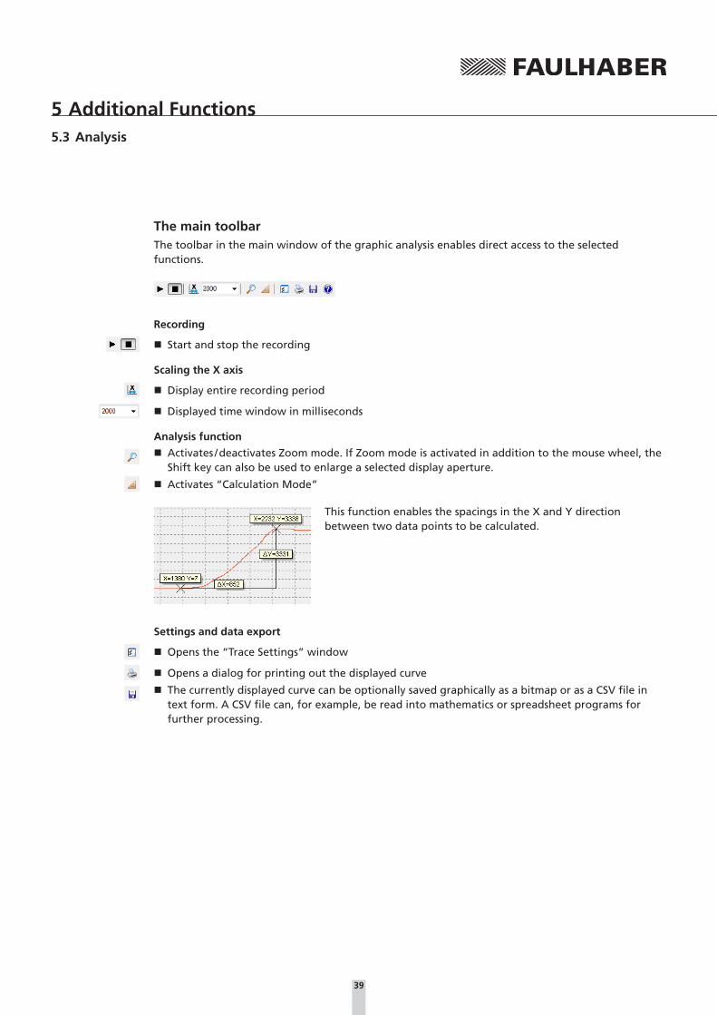
5 Additional Functions5.3 Analysis
The main toolbarThe toolbar in the main window of the graphic analysis enables direct access to the selected functions.
Recording
� Start and stop the recording
Scaling the X axis
� Display entire recording period
� Displayed time window in milliseconds
Analysis function
� Activates / deactivates Zoom mode. If Zoom mode is activated in addition to the mouse wheel, the Shift key can also be used to enlarge a selected display aperture.
� Activates “Calculation Mode”
This function enables the spacings in the X and Y direction between two data points to be calculated.
Settings and data export
� Opens the “Trace Settings” window
� Opens a dialog for printing out the displayed curve
� The currently displayed curve can be optionally saved graphically as a bitmap or as a CSV file in text form. A CSV file can, for example, be read into mathematics or spreadsheet programs for further processing.

40
5 Additional Functions5.3 Analysis
Trace settings
“Trigger” tab
� Continuous
The recording is continued continuously
� Single Shot
If the trigger source exceeds the set limit (trigger threshold) the recording is stopped
� Trigger types
Selection of predefined types of trigger
“Buffer” tab
� The given number of data packets is sent at regular intervals (time resolution) from the control to the PC
� The time resolution can be optionally speci-fied from the controller or the PC
� If the “Fixed X axis” setting is active, a fixed time period is displayed in the display window
“Curve” tab
� Defaults for the curve display can be set
� The raw data supplied by the controller can be converted into a definable unit if necessary
NOTEThe Controller always supplies raw data only. This data is then converted at the PC.
41
5 Additional Functions
5.4 Visual Basic Script programs
The FAULHABER Motion Manager enables simple sequential programs or automation scripts to be created and run on the PC within the Motion Manager.
The Visual Basic script code entered is executed using the scripting host integrated in Microsoft Win-dows.
NOTE Please note that the time response of the Microsoft Scripting Hosts is not deterministic and such script programs are provided purely for start-up tests. Use other suitable programming tools for productive operation!
5.4.1 Creating the script program
Script programs can be created or loaded in the file window and usually have the extension “*.vbs”.
Script programs always begin with “SUB MAIN” and end with “END SUB”. The Visual Basic Code can be written within this identifier.
To help you, the Motion Manager provides a selection of useful code examples, which can be used to create script programs (see Chapter 4.2.5 “The Input / Output area”).
NOTEAn explanation of the VBScript command set is given in the Microsoft Help for Visual Basic Script (“Help - Help for Visual Basic Script”).
5.4.2 Motion Manager functions
In addition to the VBScript command set there are special Motion Manager functions for exchanging data with the Motion Controllers. These functions are explained in the following and must always be invoked with the object identifier “MC.”:
NOTEQuick access to the Motion Manager functions is also obtained by using the Auto Completion (“Ctrl+SpaceBar” shortcut).

42
5 Additional Functions5.4 Visual Basic Script programs
SendCommandMC.SendCommand(STR command)
Sends an ASCII command to the Motion Controller
command: String which is to be sent to the Motion Controller.
Example:
MC.SendCommand(“V100”)
WaitAnswerSTR answer = MC.WaitAnswer(long timeout, long answ)
Waits for the given time in milliseconds for an answer from the Motion Controller.
answer: String sent by the Motion Controller.
answer = ““: No answer after timeout.
timeout: Integer value in ms, by which answer must be received.
answ: Integer value for extended details of the data to be read in.
answ = 0: Notify commands (“p”, “v”, “h”, etc.) and acknowledgements (“OK”, etc.) are filtered out.
answ = 1: All answers are read in except of acknowledgements.
answ = 3: CAN answers in integer format.
answ = 4: Notify commands only are filtered out (acknowledgements are read in).
Example:
a = MC.WaitAnswer(1000,0)
WriteToHistoryMC.WriteToHistory(STR text)
Writes the given text line into the History window of the Motion Manager.
text: String which is to be output in the History window.
Example:
MC.WriteToHistory(“Position 1 has been reached”)
SendProgFileMC.SendProgFile(long nodeadr, STR file name)
Sends the given sequential program to the Motion Controller with the relevant node address.
nodeadr: Integer value which gives the node address of the drive to be addressed.
nodeadr = -1: Program is sent to all connected nodes.
filename: String which gives the file name of the drive program, possibly with path.
Example:
CALL MC.SendProgFile(0,”progr.mcl”)

43
5 Additional Functions5.4 Visual Basic Script programs
CompareProgFilelong ret = MC.CompareProgFile(long nodeadr, STR filename)
Compares the sequential program in the Motion Controller of the corresponding node address with the program from the given file.
nodeadr: Integer value which gives the node address of the drive to be addressed.
nodeadr = -1: Read in command is sent unaddressed.
filename: String which gives the file name of the drive program, possibly with path.
ret: Integer return value.
ret = -2: Error while reading in the drive program
ret = -1: Motion Controller is not answering
ret = 0: Files are identical
ret = 1: Files are not the same
Example:
ret = MC.CompareProgFile(0,”progr.mcl”) ’Compare program file with MC pro-gram
IF ret = 1 THEN
MsgBox(“Programs not the same !”)
ELSEIF ret = -1 THEN
MsgBox(“No answer from Motion Controller !”)
END IF
SendParamFileMC.SendParamFile(long nodeadr, STR file name)
Sends the given parameter file to the Motion Controller with the relevant node address.
nodeadr: Integer value which gives the node address of the drive to be addressed.
nodeadr = -1: File is sent to all connected nodes.
filename: String which gives the file name of the parameter file, possibly with path.
Example:
CALL MC.SendParamFile(0,”para.mcp”)

44
5 Additional Functions5.4 Visual Basic Script programs
SetBinModeMC.SetBinMode(long mode1, long mode2)
Sets the binary send mode for Parameters 1 and 2 via the binary interface of Motion Controllers with RS232 interface or via the trace channel of CF series Motion Controllers with CAN interface. BinRequest can then be used to read in up to two variables simultaneously.
mode1: Integer value which gives the send mode for Parameter 1.
mode2: Integer value which gives the send mode for Parameter 2.
Available values for mode1 or mode2 (for further Trace parameters see documentation of the relevant Motion Controller):
0: Actual velocity [rpm]
1: Command velocity [rpm]
2: Controller output [integer]
24: Motor current [mA]
200: Actual position [Long]
201: Command position [Long]
44: Housing temperature [°C]
46: Coil temperature or Mosfet temperature [°C]
255: mode2 only -> Parameter 2 is not to be sent
BinRequestlong ret = MC.BinRequest(long timeout)
Data request. Reads in the parameter set with SetBinMode at the current time with time code. The results can be read in via the properties long MC.BinVal1, long MC.BinVal2, long MC.BinTimecode.
The Timecode value corresponds to a multiple of the time base used by the Motion Control-ler (see Instruction Manual of the respective control) and defines the time interval until the last transmission (send) (value between 1 and 31).
BinVal1 and BinVal2 are the results of mode1 and mode2.
ret: Integer return value.
ret = 1: Data received
ret = 0: No data received within the timeout time
timeout: Integer value in ms, by which answer must be received.
Example:
CALL MC.SetBinMode(0,1) ’Read in actual and command velocity
IF MC.BinRequest(500) THEN ’Data request
ActualVelocity = MC.BinVal1
CommandVelocity = MC.BinVal2
Timecode = MC.BinTimecode
END IF
45
5 Additional Functions5.4 Visual Basic Script programs
SendBinMC.SendBin(long value)
Sends a binary value to the active Motion Controller with serial RS232 interface.
value: Integer 8 bit value which is to be sent.
Binary values are used for setting system parameters in serial Motion Controllers only and are not usually accessible to users.
CloseComMC.CloseCom
Closes the currently active communications interface.
OpenComlong ret = MC.OpenCom
Opens the selected communications interface.
ret: Integer return value.
ret = 1: Interface successfully opened
ret = 0: Error while opening the interface
CmdExecuteMC.CmdExecute(STR command)
Runs the given command at system level. This function can be used, e.g. to start an external pro-gram.
command: String which gives the command or file name of the application to be run, possibly with path.
UpdateWindowsMC.UpdateWindows
Forwards queued Windows messages to the relevant window. If this function is regularly opened in a script program (especially in waiting loops), other Motion Manager functions (e.g. graphic analysis) are also available parallel to script processing. Notify commands are forwarded to the History window after this function is opened.
If this function is called within an endless loop the script can be cancelled using the Script button.
XonXoffMC.XonXoff (long Xon)
Activates and deactivates the Xon / Xoff protocol for Motion Controllers with serial RS232 inter-face. The activation is necessary if lots of data is to be sent quickly and consecutively.
Xon = 1: XOn/Xoff activate protocol
Xon = 0: XOn/Xoff deactivate protocol
46
5 Additional Functions5.4 Visual Basic Script programs
NodeScanMC.NodeScan
Opens the function for searching the set interfaces for drive nodes.
SelectInterfacelong ret = MC.SelectInterface(STR IntfName, long protNo)
Activates the interface with the given name (“CAN”, “COM1”, “COM2”, etc.) and the consecutive number of the protocol used (0 if only one protocol is used).
The given interface must already be set as the connection beforehand.
This function can be used to switch between two opened interfaces within a script program.
IntfName: String with the name of the required interface (as displayed in Motion Manager)
protNo = 0 for the first protocol set
ret: Integer return value.
ret = 1: Interface successfully opened
ret = 0: Unable to open the interface
NOTEExamples of Visual Basic script programs are provided in the installation directory under \Motion Manager 5\Examples.

47
5 Additional Functions5.4 Visual Basic Script programs
5.4.3 Starting the script program
The script program can be started via the Script button in the Quick Start bar (see Chapter 4.2.2 “The Quick Start bar”), via the key combination “Ctrl+R” or via the menu item “Terminal” – “Run Script”.
5.4.4 Cancelling the script program
After starting a script program a dialog appears in which the time until a user cancel option can be entered. Before this time has expire there is no access to a running script program.
If the script program runs longer than the given time the following dialog appears:
While the dialog is displayed the script program continues to run. It is now possible to prematurely quit the program by pressing the “End” button.
Press the “Continue” button to hide the dialog for the given time - it then reappears.
NOTE It is advisable to set the time until the user cancel option to the value “0” to test a program. This means it is possible to cancel the program at any time.
After finishing the program and implementing your own cancel options the value can be increased according to the program run time.

48
5 Additional Functions
5.5 Macro functions
The macro functions of the Motion Manager enable a freely definable sequence of commands, which are supported by the control, to be sent to the control with the click of the mouse. This func-tion is only available for Motion Controllers.
5.5.1 Defining macros
Macros are managed and edited in the “Macros” tab in the main window.
Macros are defined according to the following principle:
� Macro names are shown in square brackets.
� Available commands are given in the “Commands” menu item of the menu bar and the com-mand reference of the control used. If Program Editing mode is activated, commands can be copied directly in the program code.
� The additional function “WAIT” can be used to specify a delay between two commands (e.g. WAIT(1000) causes a delay of 1000ms).
The Motion Manager contains an example macro file for each Motion Controller device group; this example file is loaded automatically when the respective device is selected. This file can be changed in any way you like and further macros can be added to it. The original example macro file can be restored by completely deleting the content of the macro editor and then save. After double-clicking the active node or re-initialisation, the example macro file is again available.
NOTECommands are always transferred line by line.

49
5 Additional Functions5.5 Macro functions
5.5.2 Running macros
The defined macros are run via the “Run Macro” window. This can be opened using the “Terminal – Run Macro” menu item or using the cor-responding symbol in the QuickStart bar.
� Add new button
� Remove selected button
The context menu display all defined macros, which can be assigned to the button. It can be opened either using the arrow key or by right-clicking.
5.6 CAN
5.6.1 Advanced Motion Manager commands
Further commands are available for devices with CAN interface, in order to send CAN telegrams, to access the CANopen object dictionary or to use the state machines. These commands can either be entered directly in the command input field or used within a VBScript or macro.
GOBJ: Get ObjectReads an entry from the CANopen object dictionary via its index and subindex.
Input format: NodeNo. GOBJ Index Subindex
NodeNo.: Decimal, Index / Subindex: Hexadecimal
Example: Read out the current status word value (Index 0x6041) of node No. 3
3 GOBJ 6041 00
SOBJ: Set ObjectDescribes an entry of the CANopen object dictionary via its index and subindex.
Input format: NodeNo. SOBJ Index Subindex Data
NodeNo.: Decimal, Index / Subindex / Data: Hexadecimal (lowest byte value on the right). The number of data bytes given must correspond to the type of object entry (Int8: 1 byte, Int16: 2 byte, Int32: 4 byte). One byte is displayed by 2 hex characters (00 – FF).
Example: Change the maximum velocity (Index 0x607F: max profile velocity [Int32]) of Node No. 3 to value 500
3 SOBJ 607F 00 000001F4

50
5 Additional Functions5.6 Advanced Motion Manager commands for CAN
TRANSMIT: Transmit CAN DataSends any CAN telegram directly on a specific identifier.
Input format: TRANSMIT Identifier Data
Identifier: 3-digit hex value (000 – 9FF), Data: Hexadecimal (lowest byte value on the left, cor-responding to CAN telegram).
Example: Send NMT command “Reset Node” to Node No. 3
TRANSMIT 000 8103
In the CAN menu or in the Context menu of the Node Explorer with enabled CAN control there is the entry “Send CAN command directly”, which opens a dialog via which CAN telegrams can be entered and transferred directly (corresponds to TRANSMIT command):
PDOs can also be queried here in that a request (RTR) is sent to the corresponding identifier (“Re-mote Request” selected).
NOTE The data must be entered as hex values according to the position in the CAN telegram (byte[0] = lowest byte value = left-hand side). Spaces may be entered between the individual bytes (e.g.: 0xAF3, input F3 0A).
Further commands for controlling the NMT state machine:The commands can be entered directly with preceding Node No. and according to the menu entries under network management (NMT).
� START: Start Remote Node
� STOP: Stop Remote Node
� PREOP: Enter Pre-Operational
� STARTALL: Start all Remote Nodes
� RESET: Reset
Further commands for controlling the device control state machine:The commands can be entered directly with preceding Node No. and according to the menu entries under Device Control (DSP402).
� SHUTDOWN: Shutdown
� SWITCHON: Switch On
� DISABLE: Disable Voltage
� QUICKSTOP: Quick Stop
� DIOP: Disable Operation
� ENOP: Enable Operation
� FAULTRESET: Fault Reset

51
5 Additional Functions5.6 Advanced Motion Manager commands for CAN
Special commands for CO series Motion Controllers:
Motion Control commands
� OPMOD: Modes of Operation (Object 0x6060)
� SPOS: Set Target Position (Object 0x607A)
� MA: Move absolut (Controlword = 0x3F)
� MR: Move relative (Controlword = 0x7F)
� V: Target Velocity (Object 0x60FF)
� HM: Homing Method (Object 0x6098)
� HS: Homing Start (Controlword = 0x1F)
Query commands
� GOPMOD: Get Modes of Operation Display (Object 0x6061)
� POS: Get Position Actual Value (Object 0x6064)
� POSI: Get Position Actual Internal Value (Object 0x6063)
� TPOS: Get Position Demand Value (Object 0x6062)
� TPOSI: Get Position Demand Internal Value (Object 0x60FC)
� GN: Get Velocity Actual Value (Object 0x606C)
� GV: Get Velocity Demand Value (Object 0x606B)
� GRC: Get Current Actual Value (Object 0x6078)
� GPC: Get Peak Current (Object 0x2333.02)
� GCC: Get Continuous Current (Object 0x2333.01)
� GCL: Get Actual Current Limit (Object 0x2334)
Other commands
� SAVE / SAVE_ALL: Save all (Object 0x1010.01)
� SAVE_COM: Save Communication Parameters (Object 0x1010.02)
� SAVE_APP: Save Application Parameters (Object 0x1010.03)
� RESTORE / RESTORE_ALL: Restore all Factory Parameters (Object 0x1011.01)
� RESTORE_COM: Restore Factory Communication Parameters (Object 0x1011.02)
� RESTORE_APP: Restore Factory Application Parameters (Object 0x1011.03)
� VER: Get Software Version (Object 0x100A)
� GTYP: Get Device Name (Object 0x1008)

52
5 Additional Functions5.6 CAN
5.6.2 The CANopen object browser
The CANopen object browser can be used to view and change all entries of the CANopen object dic-tionary. It is available for FAULHABER Motion Controller with CAN interface under the “CAN – CAN-open Object dictionary - CANopen Object Browser…” menu item.
The object browser is divided into 3 tabs:
Communication: Lists the communication objects according to DS301
Manufacturer: Lists the manufacturer-specific objects
Device: Lists the objects of the drive profile according to DSP402
The name of each parameter is displayed with the index, subindex and object name as well as the value currently read out of the device. If the “New Value” column contains a “-”, it is a write-pro-tected parameter, which cannot be changed. Otherwise the current value can be changed by double-clicking the relevant row.
Press the “Send” button to transfer all new values to the control.
If the transferred parameters are to be permanently saved in the control, then perform “SAVE ALL”.
Display of the object browser requires an EDS file in XML format (XDD file) for the firmware version of the connected control to be included in the Motion Manager installation. If this is not the case, a corresponding file can be loaded and imported on starting the browser.
The displayed parameter configuration can be saved in an XDC file (Device Configuration File) using the “Save” symbol. Use the “Open File” symbol to re-load an already saved XDC file and to transfer it to the control using the “Send” button.
NOTEEDS files of the standard firmware variants, for integrating in PLC controls and other CANopen tools, are located in the installation directory under \Motion Manager 5\EDS.
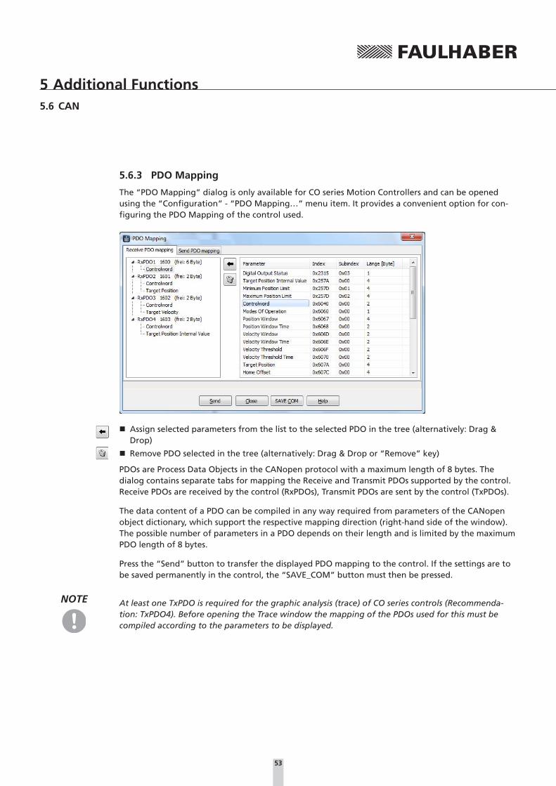
53
5 Additional Functions5.6 CAN
5.6.3 PDO Mapping
The “PDO Mapping” dialog is only available for CO series Motion Controllers and can be opened using the “Configuration” - “PDO Mapping…” menu item. It provides a convenient option for con-figuring the PDO Mapping of the control used.
� Assign selected parameters from the list to the selected PDO in the tree (alternatively: Drag & Drop)
� Remove PDO selected in the tree (alternatively: Drag & Drop or “Remove” key)
PDOs are Process Data Objects in the CANopen protocol with a maximum length of 8 bytes. The dialog contains separate tabs for mapping the Receive and Transmit PDOs supported by the control. Receive PDOs are received by the control (RxPDOs), Transmit PDOs are sent by the control (TxPDOs).
The data content of a PDO can be compiled in any way required from parameters of the CANopen object dictionary, which support the respective mapping direction (right-hand side of the window). The possible number of parameters in a PDO depends on their length and is limited by the maximum PDO length of 8 bytes.
Press the “Send” button to transfer the displayed PDO mapping to the control. If the settings are to be saved permanently in the control, the “SAVE_COM” button must then be pressed.
NOTE At least one TxPDO is required for the graphic analysis (trace) of CO series controls (Recommenda-tion: TxPDO4). Before opening the Trace window the mapping of the PDOs used for this must be compiled according to the parameters to be displayed.

54
6 Maintenance
6.1 Software update
The respective current version of the FAULHABER Motion Manager software can be downloaded from the FAULHABER internet site:
http://www.faulhaber.com/MotionManager
NOTE Under the menu item “Extras” - “Options…”, an automatic online update function can also be acti-vated which, each time Motion Manager is started, checks whether a new version is available and if so, offers to perform an update.
A manual update can also be performed at any time using the “Options” dialog.
6.2 Troubleshooting
Switchboard: +49(0)7031/638-0
eMail: [email protected]
Internet: www.faulhaber.com
55
7 Licence Agreement
End User Licence Agreement for the Faulhaber
Motion Manager of Dr. Fritz Faulhaber
GmbH & Co. KG
between
1. Dr. Fritz Faulhaber GmbH & Co. KG, Daimlerstraße 23 / 25, 71101 Schönaich, represented by the Directors Dr. Fritz Faulhaber, Gert Frech-Walter, Dr. Thomas Bertolini
- hereinafter referred to as “Faulhaber” -
and
2. you as the user
- hereinafter referred to as the “Licensee” -
Preliminary remarks:
1. Faulhaber designs miniature and micro drive systems and produces them. Faulhaber has developed the “Faulhaber Motion Manager” software (hereinafter referred to as “MoMan”). This enables the control of certain miniature and micro drive systems manufactured by Faulhaber to change their configuration and for assigning parameters. Details result from the program description of MoMan. MoMan is a standard software product which as such is not adapted to the individual needs of individual customers. Faulhaber makes MoMan available to the customer free of charge.
2. The Licensee intends using MoMan in their company. The details of this result from Article 2.
This having been explained, the Parties to the Contract conclude the following Licence Agreement
§ 1
Subject of the Contract
(1) The subject of this Contract is the granting of rights to use MoMan by Faulhaber to the Licensee.
(2) The components of MoMan are
a) the machine-readable object code,
b) the user documentation including the program description.

56
7 Licence Agreement
§ 2
Content and Scope of the Rights of Use
(1) Faulhaber grants the Licensee the unlimited spatial, non-exclusive right for an unlimited time to use MoMan for its intended use.
(2) For intended use the Licensee shall use MoMan solely for putting into service, changing the configuration and for setting the parameters of miniature or microdrive systems manufactured by Faulhaber. “Putting into service” means controlling the respective miniature or microdrive systems manufactured by Faulhaber using MoMan for the purpose of changing the configuration and for setting the parameters. In the event of such a change to the configuration and setting the parameters, the instruction manual of the respective miniature or microdrive system shall always be noted and followed and the specifications given there shall be complied with by the Licensee. The Licensee shall not use MoMan in productive operation. “Productive Operation” means using MoMan to control the respective miniature or microdrive systems manufactured by Faulhaber in the company’s on-going operations, alone or in combination with other components of an overall system. Such use does not represent intended use of MoMan. The same applies to the use of MoMan for controlling miniature and microdrive systems, which have not been manufactured by Faulhaber as well as its use to control miniature and microdrive systems, which have been manufactured by Faulhaber but which are not listed in the program description.
(3) The rights to use MoMan do not include, in particular, the right to edit (change) or to distribute without Faulhaber drive system. In this case too, MoMan shall only be distributed for no extra charge, in an unchanged form and subject to enclosure of this License Agreement. The Licensee is not entitled to demand that Faulhaber issue the source code or the source code documentation of MoMan. The Licensee is also not entitled to assign the software, the documenta-tion or parts thereof to third parties by way of rental or leasing for a limited time. Third parties are also deemed to be companies within the Licensee’s Group.
(4) Otherwise, any further use of MoMan, especially the transfer of rights of use to third parties or the granting of sub-licenses, shall require the prior explicit and written consent of Faulhaber.
This does not apply to sale of the miniature and microdrive systems, provided their proper use requires use of MoMan.
§ 3
Handover of MoMan
(1) The copy of MoMan required to exercise the rights of use granted with this Contract is made available to the Licensee in digital, machine-readable form.
(2) The Licensee also receives a copy of the user documentation in electronic form by means of downloading MoMan. This user documentation also contains the program description.
57
7 Licence Agreement
§ 4
Performance Limits
In particular, the following services by Faulhaber are not the subject of this Contract:
a) Installation of MoMan on the Licensee’s premises;
b) Individual setting of variable parameters of MoMan according to the Licensee’s requirements (customizing);
c) Individual program extensions for the Licensee (individual modifications);
d) Adjusting MoMan interfaces to the needs of the Licensee;
e) Instructing and training the Licensee’s program users;
f) Maintenance of MoMan, in particular the supply of new, subsequent program versions.
§ 5
Licensee’s claims in the event of deficiency in title
(1) Faulhaber undertakes to assign MoMan free of third parties’ rights, which stand in the way of contractual use of MoMan.
(2) In the case that third parties claim such rights, the Licensee shall immediately notify Faulhaber of the claiming of such rights by third parties and shall issue Faulhaber with all legal powers and authorities necessary to defend Faulhaber against the rights claimed by third parties.
(3) In this case (cf. No. (2)) Faulhaber is entitled at its own discretion,
a) to take suitable measures to remove the rights of third parties or their claim which impair contractual use of MoMan or
b) to change or replace MoMan in such a way that the external rights of third parties are no longer breached, if and provided that this does not impair the guaranteed function of MoMan.
If Faulhaber does not succeed to do this within a reasonable period to be set by the Licensee, the Licensee is entitled to terminate the Licence Agreement without notice.
§ 6
Licensee’s claims in the event of defects
(1) Faulhaber and the Licensee agree that it is not possible to develop software programs so that they are error-free for all application conditions. Faulhaber guarantees the suitability of MoMan in the version made available for download-ing according to Article 3 for the intended use according to Article 2 in compliance with the program description valid at the time the Contract was concluded, also made available for downloading. However, in the event that the Licensee combines MoMan with third party software, Faulhaber does not accept any defects liability for the compatibility of such third party software with MoMan.
(2) In the event of substantial deviations from the program description, Faulhaber is obliged to make subsequent im-provements. If Faulhaber does not success to remove or bypass the deviations through subsequent improvement within a reasonable period so that contractual use is made possible or if the subsequent improvement is to be deemed to have failed for other reasons, the Licensee is entitled to terminate the Licence Agreement without notice.
(3) Claims due to defects expire within one year of downloading MoMan including the user documentation. The reduc-tion in limitation period does not apply to cases of deliberate action.
58
7 Licence Agreement
§ 7
Liability, Compensation
(1) Faulhaber is basically only liable in the event of intended use of MoMan by the Licensee in accordance with Article 2.
(2) Faulhaber has unlimited liability for losses caused by deliberate intent or gross negligence. The same also applies to claims for culpably caused losses which cause fatal or physical injury, damage to health or are due to wilful conceal-ment of a defect.
(3) Faulhaber is liable in the cases of product liability according to the Product Liability Law.
(4) Faulhaber is liable for losses caused by the breach of so-called “cardinal obligations”. Cardinal obligations are funda-mental contractual duties which were decisive for conclusion of the Contract by the Licensee and which they could trust to be complied with. If Faulhaber has breached cardinal obligations due to slight negligence, the resulting liabil-ity for compensation is limited to replacement of the foreseeable loss typical for the Contract.
(5) Faulhaber does not accept any liability for the loss or destruction of data unless this has been caused by gross neg-ligence or deliberate breach of contractual or statutory duties. In the event of data loss on the Licensee’s premises, Faulhaber is liable only up to the amount of the typical cost of restoring the data which is incurred despite regular data backup according to state of the art standards.
(6) Otherwise any liability for compensation by Faulhaber is excluded, regardless of the legal reason.
(7) Following termination of this Licence Agreement the Licensee is obliged to completely delete MoMan including the user documentation and any backup copies of MoMan.
§ 8
Closing Provisions
(1) Changes or additions to this Contract shall be made in writing. If they do not satisfy this clause they are invalid. The same also applies to changes to this clause requiring the written form.
(2) This Contract shall is subject to and shall be interpreted according to the laws of the Federal Republic of Germany with the exception of the CISG - United Nations Convention on Contracts for International Sale of Goods dated 11.04.1980.
(3) The sole juridicial venue is Stuttgart, if the Licensee is a businessperson in the meaning of the Commercial Code, a legal person under public law or a public law special asset or on bringing the action the Licensee does not have any registered offices or usual place of residence (permanent address) in the Federal Republic of Germany.
(4) Should a provision of this Contract be or become invalid, all other provisions shall remain unaffected. In such a case the Parties to the Contract are obliged to participate in creating provisions which best achieve the economic result of the invalid provisions in a legally valid way.
59
Notes

MA05043, English, 5th issue, 10.2015 © DR. FRITZ FAULHABER GMBH & CO. KGSubject to change without notice
WE CREATE MOTION
DR. FRITZ FAULHABERGMBH & CO. KGAntriebssysteme
Daimlerstraße 23 / 2571101 Schönaich · GermanyTel. +49(0)7031/638-0Fax +49(0)7031/[email protected]