instruction manual compact ac geared motor international …€¦ · · 2016-07-11the user and...
TRANSCRIPT
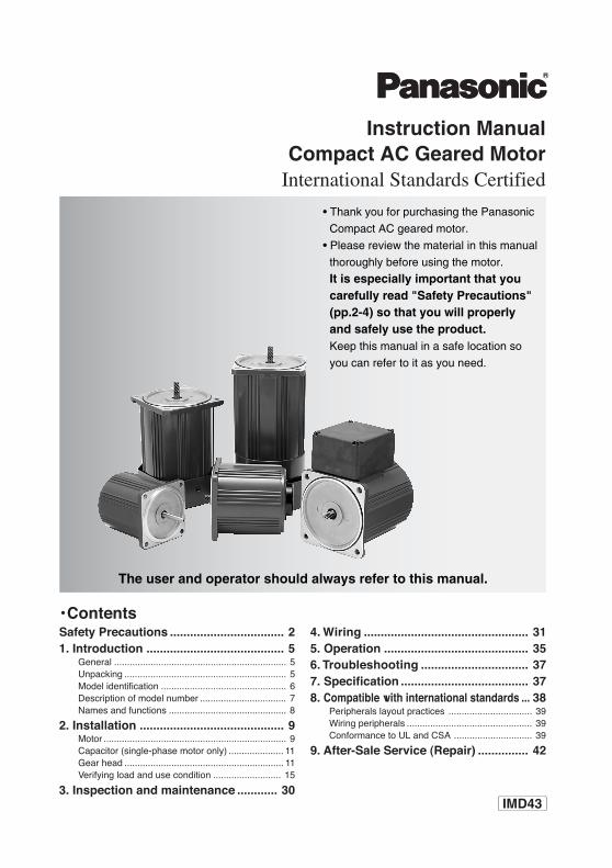
• Thank you for purchasing the Panasonic
Compact AC geared motor.
• Please review the material in this manual
thoroughly before using the motor.
It is especially important that you carefully read "Safety Precautions" (pp.2-4) so that you will properly and safely use the product.Keep this manual in a safe location so
you can refer to it as you need.
The user and operator should always refer to this manual.
Instruction ManualCompact AC Geared Motor
International Standards Certified
IMD43
Safety Precautions .................................. 21. Introduction ......................................... 5
General .................................................................. 5Unpacking .............................................................. 5Model identification ................................................ 6Description of model number ................................. 7Names and functions ............................................. 8
2. Installation ........................................... 9Motor ...................................................................... 9Capacitor (single-phase motor only) ..................... 11Gear head ............................................................. 11Verifying load and use condition .......................... 15
3. Inspection and maintenance ............ 30
• Contents4. Wiring ................................................. 315. Operation ........................................... 356. Troubleshooting ................................ 377. Specification ...................................... 378. Compatible with international standards ... 38
Peripherals layout practices ................................ 39Wiring peripherals ................................................ 39Conformance to UL and CSA .............................. 39
9. After-Sale Service (Repair) ............... 42
– 2 –
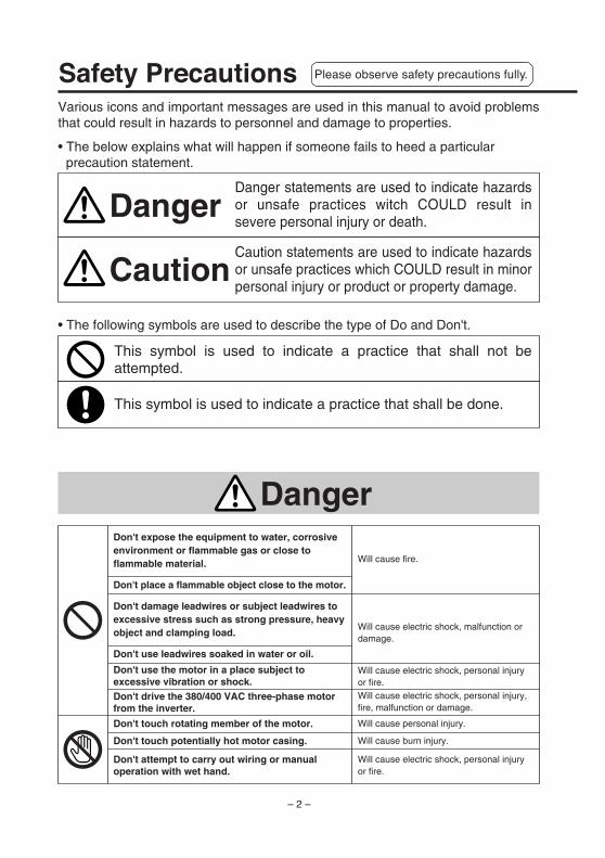
Safety Precautions
• The following symbols are used to describe the type of Do and Don't.
Caution statements are used to indicate hazards or unsafe practices which COULD result in minor personal injury or product or property damage.
This symbol is used to indicate a practice that shall not be attempted.
This symbol is used to indicate a practice that shall be done.
Caution
Danger statements are used to indicate hazards or unsafe practices witch COULD result in severe personal injury or death.
Danger
Various icons and important messages are used in this manual to avoid problems that could result in hazards to personnel and damage to properties.
• The below explains what will happen if someone fails to heed a particular precaution statement.
Don't expose the equipment to water, corrosive environment or flammable gas or close to flammable material.
Don't place a flammable object close to the motor.
Don't damage leadwires or subject leadwires to excessive stress such as strong pressure, heavy object and clamping load.
Don't use leadwires soaked in water or oil.
Don't use the motor in a place subject to excessive vibration or shock.Don't drive the 380/400 VAC three-phase motor from the inverter.
Don't touch rotating member of the motor.
Don't touch potentially hot motor casing.
Don't attempt to carry out wiring or manual operation with wet hand.
Will cause fire.
Will cause electric shock, malfunction or damage.
Will cause electric shock, personal injury or fire.Will cause electric shock, personal injury, fire, malfunction or damage.
Will cause personal injury.
Will cause burn injury.
Will cause electric shock, personal injury or fire.
Danger
Please observe safety precautions fully.
– 3 –
En
glish
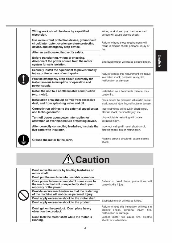
Wiring work should be done by a qualified electrician.
Use overcurrent protection device, ground-fault circuit interrupter, overtemperature protecting device, and emergency stop device.
After an earthquake, first verify safety.
Before transferring, wiring or checking, disconnect the power source from the motor system for safe isolation.
Securely install the equipment to prevent bodily injury or fire in case of earthquake.
Provide emergency stop circuit externally for instantaneous interruption of operation and power supply.
Install the unit to a nonflammable construction (e.g. metal).
Installation area should be free from excessive dust, and from splashing water and oil.
Correctly run wirings to the external speed setter and tacho-generator.
Turn off power upon power interruption or activation of overtemperature protecting device.
After correctly connecting leadwires, insulate the live parts with insulator.
Ground the motor to the earth.
Wiring work done by an inexperienced person will cause electric shock.
Failure to heed these requirements will result in electric shock, personal injury or fire.
Energized circuit will cause electric shock.
Failure to heed this requirement will result in electric shock, personal injury, fire, malfunction or damage.
Installation on a flammable material may cause fire.
Failure to heed this precaution will result in electric shock, personal injury, fire, malfunction or damage.
Incorrect wiring will result in short circuit, electric shock, personal injury, etc.
Unpredictable restarting will cause personal injury.
Incorrect wiring will result short circuit, electric shock, fire or malfunction.
Floating ground circuit will cause electric shock.
Don't move the motor by holding leadwires or motor shaft.Don't put the machine into unstable operation.Once power failure occurs, don't come close to the machine that will unexpectedly start upon recovery of the power.Provide secure mechanism so that the restarting of the machine will not cause personal injury.Don't apply excessive shock to the motor shaft.Don't apply excessive shock to the product.
Don't get on the product. Don't place heavy object on the product.
Don't lock the motor shaft while the motor is running.
Failure to heed these precautions will cause bodily injury.
Excessive shock will cause failure.
Failure to heed this instruction will result in electric shock, personal injury, fire, malfunction or damage.
Locked motor will cause fire, electric shock, or malfunction.
Caution
– 4 –
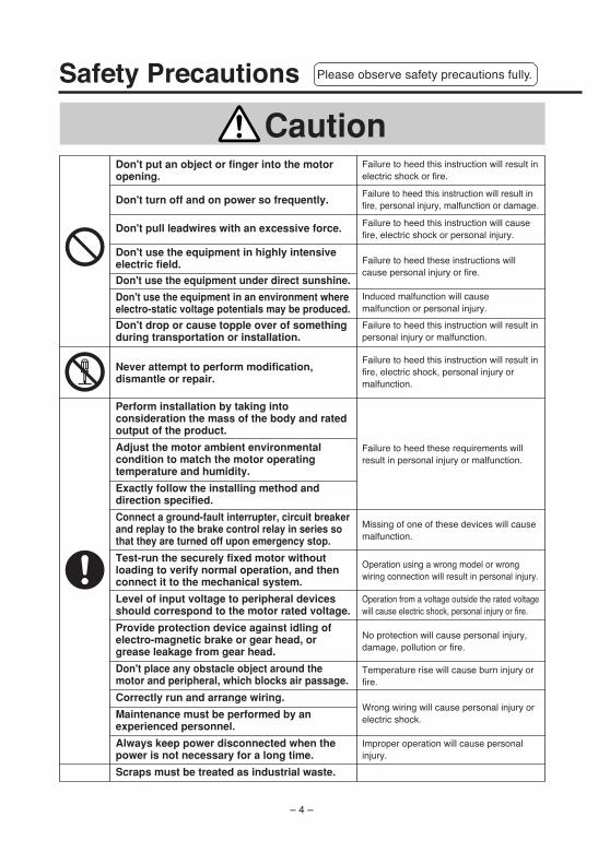
Don't put an object or finger into the motor opening.
Don't turn off and on power so frequently.
Don't pull leadwires with an excessive force.
Don't use the equipment in highly intensive electric field.
Don't use the equipment under direct sunshine.
Don't use the equipment in an environment where electro-static voltage potentials may be produced.
Don't drop or cause topple over of something during transportation or installation.
Never attempt to perform modification, dismantle or repair.
Perform installation by taking into consideration the mass of the body and rated output of the product.
Adjust the motor ambient environmental condition to match the motor operating temperature and humidity.
Exactly follow the installing method and direction specified.
Connect a ground-fault interrupter, circuit breaker and replay to the brake control relay in series so that they are turned off upon emergency stop.
Test-run the securely fixed motor without loading to verify normal operation, and then connect it to the mechanical system.
Level of input voltage to peripheral devices should correspond to the motor rated voltage.
Provide protection device against idling of electro-magnetic brake or gear head, or grease leakage from gear head.
Don't place any obstacle object around the motor and peripheral, which blocks air passage.
Correctly run and arrange wiring.
Maintenance must be performed by an experienced personnel.
Always keep power disconnected when the power is not necessary for a long time.
Scraps must be treated as industrial waste.
!
Caution
Safety Precautions Please observe safety precautions fully.
– 5 –
En
glish
1. IntroductionGeneral
Thisis a compact AC geared-motor having multiple international standard certifications. To use this
product for a prolonged period, read this manual thoroughly.
This is designed for use in corporation with general purpose industrial devices. The product must
be handled by experienced personnel familiar with the product.
Unpacking
• Proceed as follows:• First open the top of the packing and check the units for damage in transit.
• Check the motor nameplate for the model number, output, No. of poles, voltage, frequency,
etc.
Do not use the product if it does not meet your specification (if you dare to use it, burn
injury or fire may result).
• A single-phase motor comes with capacitor. Check the rated capacitance and voltage on the
nameplate. Do not use the accessory capacitor if it does not meet your specification (if you
dare to use it, you may be injuried or may have fire).
• Check a gear ratio on the nameplate. Do not use it if it does not meet your specification (if you
dare to use it, you may be injuried or may have fire).
Should you find any discrepancy in the product, consult your local dealer.
– 6 –
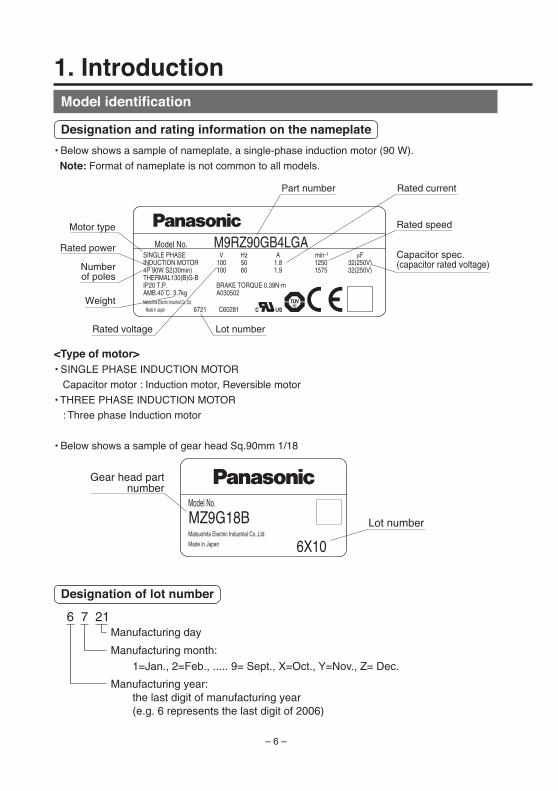
1. Introduction
Designation of lot number
Model identification
Designation and rating information on the nameplate
• Below shows a sample of nameplate, a single-phase induction motor (90 W).
Note: Format of nameplate is not common to all models.
Part number
Numberof poles
Rated power
Rated voltage
Rated current
Rated speed
Capacitor spec.(capacitor rated voltage)
Lot number
Weight
Motor type
SUDSUD
A030502AMB.40˚C 3.7kg
M9RZ90GB4LGAModel No.V Hz A min–1
100 50 1.8 1250
BRAKE TORQUE 0.39N•m
100 60 1.9 1575
SINGLE PHASEINDUCTION MOTOR4P 90W S2(30min)THERMAL130(B)G-BIP20 T.P.
Made in Japan
µF32(250V)32(250V)
C602816721Matsushita Electric Industrial Co.,Ltd.
<Type of motor>• SINGLE PHASE INDUCTION MOTOR
Capacitor motor : Induction motor, Reversible motor
• THREE PHASE INDUCTION MOTOR
: Three phase Induction motor
• Below shows a sample of gear head Sq.90mm 1/18
Manufacturing day
Manufacturing year: the last digit of manufacturing year (e.g. 6 represents the last digit of 2006)
Manufacturing month: 1=Jan., 2=Feb., ..... 9= Sept., X=Oct., Y=Nov., Z= Dec.
6 7 21
Lot number
Gear head partnumber
6X10
Model No.
MZ9G18BMade in Japan
Matsushita Electric Industrial Co.,Ltd.
– 7 –
En
glish
* Induction motor and reversible motor are single phase motor.
Gear head
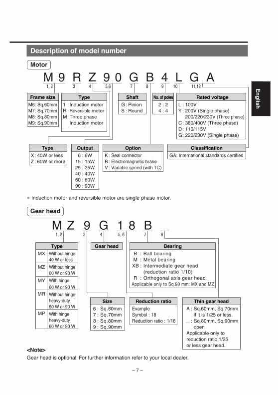
M Z 9 G 1 8 B
Type
MX
MZ
MY
MR
MP
Without hinge40 W or less
Without hinge60 W or 90 W
With hinge60 W or 90 W
Without hingeheavy-duty60 W or 90 W
With hingeheavy-duty60 W or 90 W
Size
6 : Sq.60mm7 : Sq.70mm8 : Sq.80mm9 : Sq.90mm
Reduction ratio
ExampleSymbol : 18Reduction ratio : 1/18
Thin gear head
A : Sq.60mm, Sq.70mmif it is 1/25 or less.
: Sq.80mm, Sq.90mmopen
Applicable only to reduction ratio 1/25 or less gear head.
Bearing
B : Ball bearingM : Metal bearingXB : Intermediate gear head
(reduction ratio 1/10)R : Orthogonal axis gear head
Applicable only to Sq.90 mm: MX and MZ
Gear head
1, 2 3 4 5, 6 7 8
Description of model number
Motor
M 9 R Z 9 0 G B 4 L G AFrame size
M6: Sq.60mmM7: Sq.70mmM8: Sq.80mmM9: Sq.90mm
Output
6 : 6W15 : 15W25 : 25W40 : 40W60 : 60W90 : 90W
Type
X: 40W or lessZ : 60W or more
Type
1 : Induction motorR : Reversible motorM: Three phase
Induction motor
Option
K : Seal connectorB : Electromagnetic brake V : Variable speed (with TC)
Classification
GA: International standards certified
Shaft
G : PinionS : Round
Rated voltage
L : 100VY : 200V (Single phase)
200/220/230V (Three phase)C : 380/400V (Three phase)D : 110/115VG: 220/230V (Single phase)
No. of poles
2 : 24 : 4
1, 2 3 4 5,6 7 8 9 10 11,12
<Note>Gear head is optional. For further information refer to your local dealer.
– 8 –
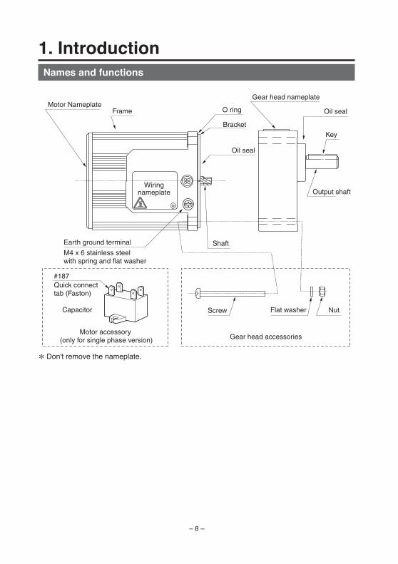
1. IntroductionNames and functions
Motor NameplateFrame O ring
Bracket
Oil seal
Oil seal
Motor accessory (only for single phase version) Gear head accessories
Gear head nameplate
Screw NutFlat washer
Shaft
Output shaft
Earth ground terminal
M4 x 6 stainless steel with spring and flat washer
Key
Quick connect tab (Faston)
#187
Capacitor
Wiringnameplate
* Don't remove the nameplate.
– 9 –
En
glish
2. InstallationMotor
Installation location
Install the motor as described to prolong the motor lifetime in a place where;
(1) is free from rain and direct sunlight.
(2) is free from vibration 4.9 m/s2 or more; shock, dust, iron powder or oil mist; splash of water. oil
and grinding fluid; and away from flammable materials, corrosive gas (H2S, SO2, NO2, Cl2, etc.)
or flammable gas.
(3) is enough ventilated dry and clean keeping oil, water, dust and heat away.
(4) you can check and clean the motor easily.
(5) is not in a closed environment where the motor temperature may increase. This may result in
the motor life shortened.
Environmental condition
Description
–10°C to 40°C (no freezing) *1
85% RH or below (no dewing)
–10°C to 60°C (no freezing) *2
4.9 m/s2 or below (10 to 60 Hz)
1000 m max.
Item
Ambient temperature
Ambient humidity
Storage temperature
Vibration
Altitude
*1) Measurement taken at a point 5 cm from the motor.
*2) Allowable range for a relatively short period, for example, during transportation.
Installation
The motor can be installed vertically or horizontally but leadwires should be directed downward.
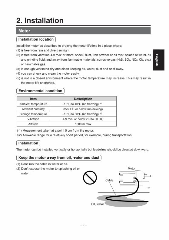
Keep the motor away from oil, water and dust
(1) Don't run the cable in water or oil.
(2) Don't expose the motor to splashing oil or
water.
Oil, water
Cable
Motor
– 10 –
2. InstallationStress on lead
Do not stress where a cable coming out on the motor housing and where the cable is connected.
Output shaft allowable load
(1) Design the mechanical system so that it can withstand the radial load and thrust load allowed to
be applied to the shaft of the specified model during installation and operation.
(2) When installing a rigid coupling, pay special attention to minimize bending load that may cause
damage to the shaft or shorten the life of bearings.
(3) To keep the radial load caused by center runout within the tolerance, use high stiffness flexible
coupling.
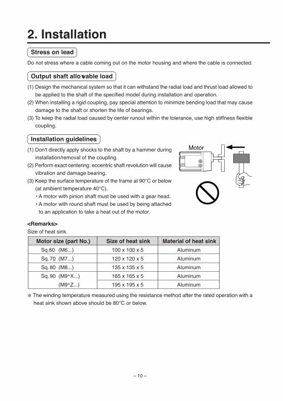
Installation guidelines
(1) Don't directly apply shocks to the shaft by a hammer during
installation/removal of the coupling.
(2) Perform exact centering: eccentric shaft revolution will cause
vibration and damage bearing.
(3) Keep the surface temperature of the frame at 90°C or below
(at ambient temperature 40°C).
• A motor with pinion shaft must be used with a gear head.
• A motor with round shaft must be used by being attached
to an application to take a heat out of the motor.
<Remarks>Size of heat sink
* The winding temperature measured using the resistance method after the rated operation with a
heat sink shown above should be 80°C or below.
Motor
Motor size (part No.)
Sq.60 (M6...)
Sq. 70 (M7...)
Sq. 80 (M8...)
Sq. 90 (M9*X...)
(M9*Z...)
Size of heat sink
100 x 100 x 5
120 x 120 x 5
135 x 135 x 5
165 x 165 x 5
195 x 195 x 5
Material of heat sink
Aluminum
Aluminum
Aluminum
Aluminum
Aluminum
– 11 –
En
glish
Capacitor (single-phase motor only)
Mounting
Secure the capacitor using M4 screw (Not come with the motor). (Recommended torque to
tihgten : 0.74-1.0 N·m)
Gear head
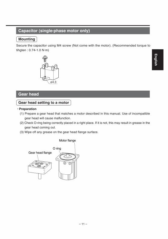
Gear head setting to a motor
• Preparation(1) Prepare a gear head that matches a motor described in this manual. Use of incompatible
gear head will cause malfunction.
(2) Check O-ring being correctly placed in a right place. If it is not, this may result in grease in the
gear head coming out.
(3) Wipe off any grease on the gear head flange surface.
O ring
Motor flange
Gear head flange
ø4.3
– 12 –
2. Installation• Assembling
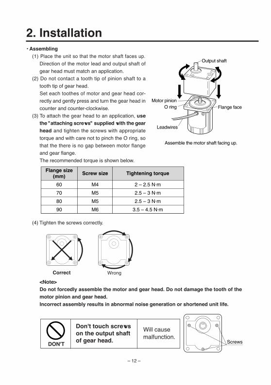
(1) Place the unit so that the motor shaft faces up.
Direction of the motor lead and output shaft of
gear head must match an application.
(2) Do not contact a tooth tip of pinion shaft to a
tooth tip of gear head.
Set each toothes of motor and gear head cor-
rectly and gently press and turn the gear head in
counter and counter-clockwise.
(3) To attach the gear head to an application, usethe "attaching screws" supplied with the gearhead and tighten the screws with appropriate
torque and with care not to pinch the O ring, so
that the there is no gap between motor flange
and gear flange.
The recommended torque is shown below.
(4) Tighten the screws correctly.
<Note>Do not forcedly assemble the motor and gear head. Do not damage the tooth of themotor pinion and gear head.Incorrect assembly results in abnormal noise generation or shortened unit life.
Screws
Correct Wrong
Assemble the motor shaft facing up.
O ringMotor pinion
Leadwires
Flange face
Output shaft
60
70
80
90
Flange size(mm)
M4
M5
M5
M6
Screw size
2 – 2.5 N·m
2.5 – 3 N·m
2.5 – 3 N·m
3.5 – 4.5 N·m
Tightening torque
Don't touch screwson the output shaftof gear head.
Will causemalfunction.
DON'T
– 13 –
En
glish
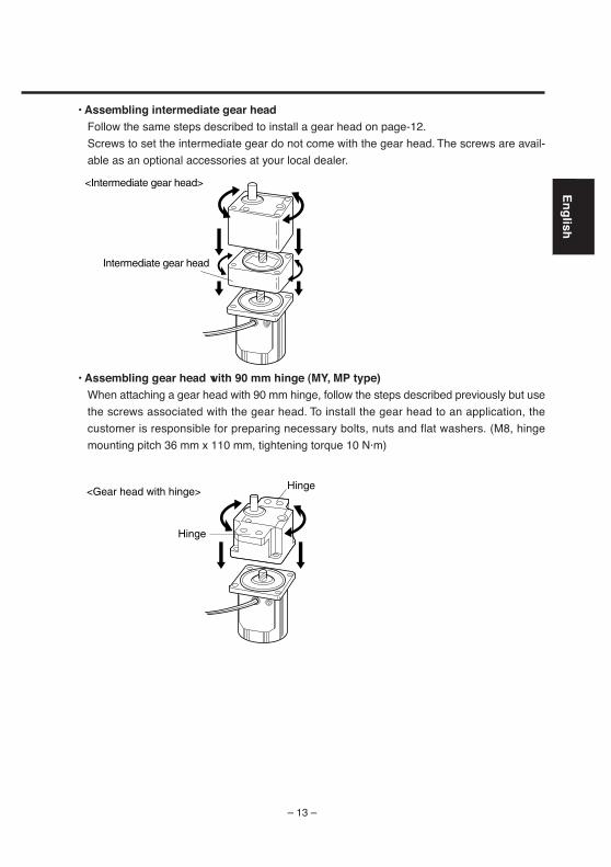
• Assembling intermediate gear headFollow the same steps described to install a gear head on page-12.
Screws to set the intermediate gear do not come with the gear head. The screws are avail-
able as an optional accessories at your local dealer.
• Assembling gear head with 90 mm hinge (MY, MP type)When attaching a gear head with 90 mm hinge, follow the steps described previously but use
the screws associated with the gear head. To install the gear head to an application, the
customer is responsible for preparing necessary bolts, nuts and flat washers. (M8, hinge
mounting pitch 36 mm x 110 mm, tightening torque 10 N·m)
Intermediate gear head
<Intermediate gear head>
Hinge
Hinge
<Gear head with hinge>
– 14 –
Considerations for installation of gear head
You may experience a sliping gear contact due to broken pinion tooth, locked gear or leaked
grease as the gear head life comes closer.
Place a safety device to keep safe operation at any time even if such problems take place.
• Place a drop-proof device in an verticlly motioned application like a lifter.
• Place a device to open the door in a door application just in case the gear head is locked.
• Place an oil pan to prevent oil from coming out in an application like food/textile etc.
• Do not place an encoder, sensor, contact, etc near a gear head where the grease may
leaking out. If not, please have a protection from grease.
• Have a routain check of the gear head to avoid unexpected accident.
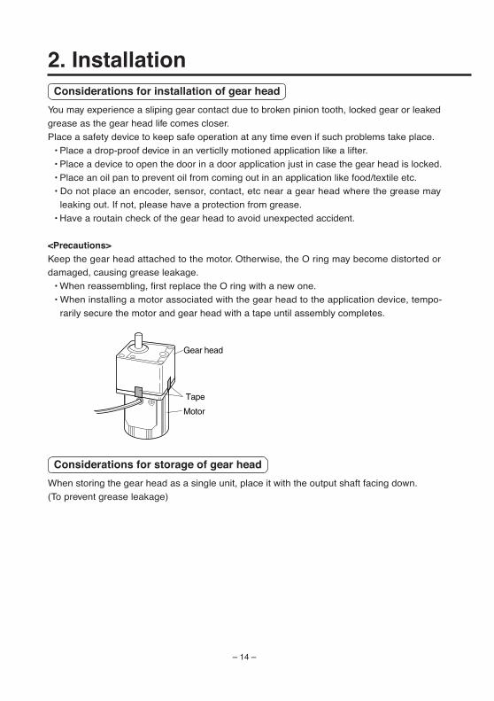
<Precautions>Keep the gear head attached to the motor. Otherwise, the O ring may become distorted or
damaged, causing grease leakage.
• When reassembling, first replace the O ring with a new one.
• When installing a motor associated with the gear head to the application device, tempo-
rarily secure the motor and gear head with a tape until assembly completes.
Considerations for storage of gear head
When storing the gear head as a single unit, place it with the output shaft facing down.
(To prevent grease leakage)
Motor
Gear head
Tape
2. Installation
– 15 –
En
glish
Verifying load and use condition
To use your equipment for a long period, check the use condition. Some specific conditions
will cause heat rise or damage. Check the conditions and use the units within the allowable
range.
• Standard lifeThe table right shows the standard life of mo-
tor with a gear head. The typical life of a motor
(round shaft) is 10,000 hours. Standard life of
oil seal (pinion shaft type) performance is 5,000
hours.
The standard life is calculated under conditions;
8 hours operation per day(service factor :
Sf=1.0) Ambient temperature and humidity
Constant load(allowable gear head shaft
torque).
• Service factor (Sf)
The service factor (Sf) varies depending on the intensity of load shock and operating hours. The
table below shows the loading conditions and corresponding service factors.
Life expectancy =Standard life
Service factor (Sf)
Type of load
Uniform load
Light impact
Medium impact
High impact
Example of load
Continues one way operation
Start, stop, cam impact
Instant CW/CCW, instant stop
Frequent repetition of medium impact
Service factor
5 hours/day
0.8
1.2
1.5
2.5
8 hours/day
1.0
1.5
2.0
3.0
24 hours/day
1.5
2.0
2.5
3.5
• Allowable shaft torqueThe required allowable shaft torque TA of the gear head can be determined based on the ser-
vice factor and actual load torque T1:
TA = T1 x Sf
Select a gear head and motor so that the required torque (continuous value) is within the range
shown in the table below. Note that torque T1 is not allowed to exceed the allowable shaft
torque TA regardless of Sf.
Gear head type
MX6G*B(A) thru MX9G*B
MZ9G*B, MY9G*B
MR9G*B, MP9G*B
MX9G*R
MZ9G*R
MX6G*M(A) thru MX9G*M
M4GA*F
“ * ” in model number represents gear ratio.
Standard life
10,000 hours
5,000 hours
2,000 hours
– 16 –
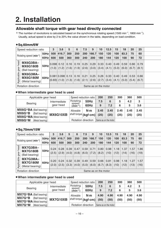
2. InstallationAllowable shaft torque with gear head directly connected* The number of revolutions is calculated based on the synchronous rotating speed (1500 min–1, 1800 min–1).
Usually, actual speed is slow by 2 to 20% the value shown in the table, depending on load condition.
•Sq.60mm/6W
•When intermediate gear head is used
Applicable gear head
Bearing Intermediate
gear head
Intermediate gear head
MX6G10XBAllowable
shaft torque
50Hz60Hz
N•m(kgf•cm)
Rotation direction Same as on the motor
Speed reduction ratio
2.45
(25)
2.45
(25)
2.45
(25)
2.45
(25)
2.45
(25)
5003
3.6
2506
7.2
30056
3604.25
2007.59
MX6G*BA (Ball bearing)MX6G*B (Ball bearing)MX6G*MA (Metal bearing)MX6G*M (Metal bearing)
3
500
600
3.6
416.7
500
5
300
360
6
250
300
7.5
200
240
9
166.7
200
10
150
180
12.5
120
144
15
100
120
18
83.3
100
20
75
90
25
60
72
Same as on the motor
0.098(1.0)
0.12(1.2)
0.16(1.6)
0.19(1.9)
0.25(2.6)
0.29(3.0)
0.33(3.4)
0.40(4.1)
0.49(5.0)
0.59(6.0)
0.66(6.7)
0.79(8.1)
0.081(0.83)
0.098(1.0)
0.13(1.3)
0.16(1.6)
0.21(2.1)
0.25(2.6)
0.26(2.7)
0.33(3.4)
0.40(4.1)
0.49(5.0)
0.53(5.4)
0.66(6.7)
50Hz60Hz
50Hz
60Hz
Speed reduction ratio
Rotation direction
Rotating speed (min–1)
App
licab
le g
ear h
ead
MX6G3BA–MX6G180B(Ball bearing)
MX6G3MA–MX6G180M(Metal bearing)
•Sq.70mm/15W
•When intermediate gear head is used
Applicable gear head
Bearing
MX7G10XB
Rotating speed (min–1)
Rotating speed (min–1)
Allowable shaft torque
50Hz60Hz
N•m(kgf•cm)
Rotation direction Same as on the motor
Speed reduction ratio
4.90
(50)
4.90
(50)
4.90
(50)
4.90
(50)
4.90
(50)
5003
3.6
2506
7.2
30056
3604.25
2007.59
MX7G*BA (Ball bearing)MX7G*B (Ball bearing)MX7G*MA (Metal bearing)MX7G*M (Metal bearing)
Same as on the motor
3
500
600
3.6
416.7
500
5
300
360
6
250
300
7.5
200
240
9
166.7
200
10
150
180
12.5
120
144
15
100
120
18
83.3
100
20
75
90
25
60
72
0.20(2.0)
0.24(2.5)
0.32(3.3)
0.39(4.0)
0.49(5.0)
0.59(6.0)
0.66(6.7)
0.81(8.3)
0.98(10)
1.18(12)
1.27(13)
1.57(16)
0.24(2.5)
0.28(2.9)
0.39(4.0)
0.47(4.8)
0.59(6.0)
0.71(7.2)
0.80(8.2)
0.98(10)
1.18(12)
1.37(14)
1.57(16)
1.86(19)
50Hz60Hz
50Hz
60Hz
Speed reduction ratio
Rotation direction
Rotating speed (min–1)
MX7G3BA–MX7G180B(Ball bearing)
MX7G3MA–MX7G180M(Metal bearing)A
pplic
able
gea
r hea
d
– 17 –
En
glish
Opposite to that of the motor
2.45
(25)
2.45
(25)
2.45
(25)
2.45
(25)
6002.53
7502
2.4
9001.72
10001.51.8
2.45
(25)
12001.31.5
2.45
(25)
15001
1.2
2.45
(25)
18000.81
30
50
60
36
41.7
50
50
30
36
60
25
30
75
20
24
90
16.7
20
100
15
18
120
12.5
15
150
10
12
180
8.3
10
Opposite to that of the motor
0.95(9.7)
1.18(12)
1.57(16)
1.86(19)
2.25(23)
2.45(25)
2.45(25)
0.79(8.1)
0.95(9.7)
1.27(13)
1.57(16)
1.86(19)
2.25(23)
2.45(25)
Opposite to that of the motor
4.90
(50)
4.90
(50)
4.90
(50)
4.90
(50)
4.90
(50)
4.90
(50)
4.90
(50)
6002.53
7502
2.4
9001.72
10001.51.8
12001.31.5
15001
1.2
18000.81
Opposite to that of the motor
30
50
60
36
41.7
50
50
30
36
60
25
30
75
20
24
90
16.7
20
100
15
18
120
12.5
15
150
10
12
180
8.3
10
1.86(19)
2.25(23)
3.23(33)
3.82(39)
4.80(49)
2.25(23)
2.74(28)
3.82(39)
4.61(47)
4.90(50)
4.90(50)
4.90(50)
Allowable shaft torque: upper line = N•m, lower line = kgf•cm
Allowable shaft torque: upper line = N•m, lower line = kgf•cm
– 18 –
2. Installation
•Sq.80mm/25W
•Sq.90mm/40W
MX8G10XBAllowable
shaft torque
50Hz60Hz
NN•m(kgf•cm)
7.84
(80)
7.84
(80)
7.84
(80)
7.84
(80)
7.84
(80)
5003
3.6
2506
7.2
30056
3604.25
2007.59
MX8G*B(Ball bearing)MX8G*M
(Metal bearing)
0.39(4.0)
0.47(4.8)
0.66(6.7)
0.78(8.0)
0.98(10)
1.18(12)
1.27(13)
1.57(16)
1.96(20)
2.35(24)
2.55(26)
3.14(32)
0.32(3.3)
0.39(4.0)
0.55(5.6)
0.66(6.7)
0.81(8.3)
0.98(10)
1.08(11)
1.27(13)
1.57(16)
1.96(20)
2.06(21)
2.65(27)
3
500
600
3.6
416.7
500
5
300
360
6
250
300
7.5
200
240
9
166.7
200
10
150
180
12.5
120
144
15
100
120
18
83.3
100
20
75
90
25
60
7250Hz60Hz
50Hz
60Hz
MX8G3B–MX8G180B(Ball bearing)
MX8G3M–MX8G180M(Metal bearing)
Bearing
MX9G10XB
50Hz60Hz
N•m(kgf•cm)
9.80
(100)
9.80
(100)
9.80
(100)
9.80
(100)
9.80
(100)
5003
3.6
2506
7.2
30056
3604.25
2007.59
MX9G*B(Ball bearing)MX9G*M
(Metal bearing)
0.66(6.7)
0.78(8.0)
1.08(11)
1.27(13)
1.57(16)
1.86(19)
2.25(23)
2.74(28)
3.23(33)
3.92(40)
4.41(45)
5.29(54)
0.55(5.6)
0.66(6.7)
0.90(9.2)
1.08(11)
1.27(13)
1.57(16)
1.76(18)
2.25(23)
2.74(28)
3.23(33)
3.53(36)
4.41(45)
3
500
600
3.6
416.7
500
5
300
360
6
250
300
7.5
200
240
9
166.7
200
10
150
180
12.5
120
144
15
100
120
18
83.3
100
20
75
90
25
60
7250Hz60Hz
50Hz
60Hz
MX9G3B–MX9G180B(Ball bearing)
MX9G3M–MX9G180M(Metal bearing)
Allowable shaft torque with gear head directly connected* The number of revolutions is calculated based on the synchronous rotating speed (1500 min–1, 1800 min–1).
Usually, actual speed is slow by 2 to 20% the value shown in the table, depending on load condition.
Applicable gear head
Bearing Intermediate
gear head
Intermediate gear head
50Hz60Hz
Rotation direction Same as on the motor
Speed reduction ratio
Same as on the motor
Speed reduction ratio
Rotating speed (min–1)
App
licab
le g
ear h
ead
Applicable gear headRotating speed (min–1)
Rotating speed (min–1)
Allowable shaft torque
Rotation direction Same as on the motor
Speed reduction ratio
Same as on the motor
Speed reduction ratio
Rotation direction
Rotating speed (min–1)
App
licab
le g
ear h
ead
Rotation direction
•When intermediate gear head is used
•When intermediate gear head is used
– 19 –
En
glish
7.84
(80)
7.84
(80)
7.84
(80)
7.84
(80)
7.84
(80)
7.84
(80)
7.84
(80)
6002.53
7502
2.4
9001.72
10001.51.8
12001.31.5
15001
1.2
18000.81
3.82(39)
4.61(47)
6.37(65)
7.64(78)
7.84(80)
3.14(32)
3.82(39)
5.29(54)
6.37(65)
7.84(80)
30
50
60
36
41.7
50
50
30
36
60
25
30
75
20
24
90
16.7
20
100
15
18
120
12.5
15
150
10
12
180
8.3
10
9.80
(100)
9.80
(100)
9.80
(100)
9.80
(100)
9.80
(100)
9.80
(100)
9.80
(100)
6002.53
7502
2.4
9001.72
10001.51.8
12001.31.5
15001
1.2
18000.81
6.37(65)
7.94(81)
9.80(100)
9.80(100)
5.29(54)
6.37(65)
8.82(90)
9.80(100)
30
50
60
36
41.7
50
50
30
36
60
25
30
75
20
24
90
16.7
20
100
15
18
120
12.5
15
150
10
12
180
8.3
10
Opposite to that of the motor
Opposite to that of the motor
Opposite to that of the motor
Opposite to that of the motor
Allowable shaft torque: upper line = N•m, lower line = kgf•cm
Allowable shaft torque: upper line = N•m, lower line = kgf•cm
– 20 –
Bearing
Allowable shaft torque with gear head directly connected* The number of revolutions is calculated based on the synchronous rotating speed (1500 min–1, 1800 min–1).
Usually, actual speed is slow by 2 to 20% the value shown in the table, depending on load condition.
Applicable gear head
Bearing Intermediate
gear head
Intermediate gear head
Rotation direction
Speed reduction ratio
Speed reduction ratio
Rotating speed (min–1)
App
licab
le g
ear h
ead
Applicable gear headRotating speed (min–1)
Rotating speed (min–1)
Allowable shaft torque
Rotation direction
Speed reduction ratio
Speed reduction ratio
Rotation direction
Rotating speed (min–1)
App
licab
le g
ear h
ead
Rotation direction
•When intermediate gear head is used
•When intermediate gear head is used
•Sq.90mm/60W
•Sq.90mm/90W
MZ9G10XBAllowable
shaft torque
50Hz60Hz
N•m(kgf•cm)
Opposite to that of the motor
Opposite to that of the motor
19.6
(200)
19.6
(200)
19.6
(200)
19.6
(200)
19.6
(200)
6002.53
5003
3.6
2506
7.2
30056
3604.25
MZ9G*B(Ball bearing, without hinge)
MY9G*B(Ball bearing, with hinge)
0.98(9.99)
1.18(12)
1.57(16)
1.96(20)
2.35(24)
2.94(30)
3.14(32)
3.92(40)
4.70(48)
5.59(57)
6.27(64)
7.55(77)
0.78(8.0)
0.98(9.99)
1.37(14)
1.57(16)
1.96(20)
2.35(24)
2.65(27)
3.33(34)
3.92(40)
4.70(48)
5.29(54)
6.47(66)
3
500
600
3.6
416.7
500
5
300
360
6
250
300
7.5
200
240
9
166.7
200
10
150
180
12.5
120
144
15
100
120
18
83.3
100
20
75
90
25
60
72
Same as on the motor Opposite to that of the motor
50Hz60Hz
50Hz
60Hz
MZ9G3B–MZ9G200B
MY9G3B–MY9G200B
MZ9G10XB
50Hz60Hz
N•m(kgf•cm)
19.6
(200)
19.6
(200)
19.6
(200)
19.6
(200)
19.6
(200)
6002.53
5003
3.6
2506
7.2
30056
3604.25
MZ9G*B(Ball bearing, without hinge)
MY9G*B(Ball bearing, with hinge)
Same as on the motor Opposite to that of the motor
1.18(12)
1.37(14)
1.86(19)
2.25(23)
2.84(29)
3.43(35)
3.72(38)
4.70(48)
5.68(58)
6.76(69)
7.55(77)
9.21(94)
1.37(14)
1.67(17)
2.25(23)
2.74(28)
3.43(35)
4.12(42)
4.51(46)
5.68(58)
6.76(69)
8.04(82)
9.02(92)
10.9(111)
50Hz60Hz
50Hz
60Hz
3
500
600
3.6
416.7
500
5
300
360
6
250
300
7.5
200
240
9
166.7
200
10
150
180
12.5
120
144
15
100
120
18
83.3
100
20
75
90
25
60
72
MZ9G3B–MZ9G200B
MY9G3B–MY9G200B
(Ball bearing,without hinge)
(Ball bearing,with hinge)
(Ball bearing,without hinge)
(Ball bearing,with hinge)
2. Installation
– 21 –
En
glish
Same as on the motor
19.6
(200)
19.6
(200)
19.6
(200)
19.6
(200)
19.6
(200)
19.6
(200)
7502
2.4
9001.72
10001.51.8
12001.31.5
19.6
(200)
15001
1.2
18000.83
1
20000.750.9
9.11(93)
11.0(112)
15.2(155)
17.8(182)
19.6(200)
7.55(77)
9.11(93)
12.6(129)
15.2(155)
19.6(200)
30
50
60
36
41.7
50
50
30
36
60
25
30
75
20
24
90
16.7
20
100
15
18
120
12.5
15
180
8.3
10
200
7.5
9
150
10
12
Same as on the motor
Same as on the motor
19.6
(200)
19.6
(200)
19.6
(200)
19.6
(200)
19.6
(200)
19.6
(200)
7502
2.4
9001.72
10001.51.8
12001.31.5
15001
1.2
18000.83
1
19.6
(200)
20000.750.9
Same as on the motor
10.9(111)
13.0(133)
18.3(187)
19.6(200)
13.0(133)
15.7(160)
19.6(200)
19.6(200)
30
50
60
36
41.7
50
50
30
36
60
25
30
75
20
24
90
16.7
20
100
15
18
120
12.5
15
180
8.3
10
200
7.5
9
150
10
12
Allowable shaft torque: upper line = N•m, lower line = kgf•cm
Allowable shaft torque: upper line = N•m, lower line = kgf•cm
– 22 –
2. Installation
•Without hinge Sq.90mm/60W
15.2(155)
18.2(186)
22.1(225)
26.5(270)
29.4(300)
12.7(130)
15.2(155)
18.6(190)
22.1(225)
24.6(251)
29.4(300)
50
30
36
60
25
30
75
20
24
90
16.7
20
100
15
18
120
12.5
15
150
10
12
180
8.3
10
200
7.5
9
Same as on the motor
50Hz60Hz
50Hz
60Hz
MR9G50B–MR9G200B
Allowable shaft torque: upper line = N•m, lower line = kgf•cm
•With hinge Sq.90mm/60W Allowable shaft torque: upper line = N•m, lower line = kgf•cm
15.2(155)
18.2(186)
22.1(225)
26.5(270)
29.4(300)
12.7(130)
15.2(155)
18.6(190)
22.1(225)
24.6(251)
29.4(300)
50
30
36
60
25
30
75
20
24
90
16.7
20
100
15
18
120
12.5
15
150
10
12
180
8.3
10
200
7.5
9
Same as on the motor
50Hz60Hz
50Hz
60Hz
MP9G50B–MP9G200B
MZ9G10XB
50Hz60Hz
N•m(kgf•cm)
29.4
(300)
29.4
(300)
29.4
(300)
29.4
(300)
29.4
(300)
10001.51.8
9001.72
5003
3.6
6002.53
7502
2.4
MR9G*B(Ball bearing, without hinge)
MZ9G10XB
50Hz60Hz
N•m(kgf•cm)
Same as on the motor
Same as on the motor
29.4
(300)
29.4
(300)
29.4
(300)
29.4
(300)
29.4
(300)
10001.51.8
9001.72
5003
3.6
6002.53
7502
2.4
MP9G*B((Ball bearing, with hinge)
Bearing
Allowable shaft torque with heavy duty gear head directly connected* The number of revolutions is calculated based on the synchronous rotating speed (1500 min–1, 1800 min–1).
Usually, actual speed is slow by 2 to 20% the value shown in the table, depending on load condition.
Applicable gear head
Bearing Intermediate
gear head
Intermediate gear head
Rotation direction
Speed reduction ratio
Speed reduction ratio
Rotating speed (min–1)
App
licab
le g
ear h
ead
Applicable gear headRotating speed (min–1)
Rotating speed (min–1)
Allowable shaft torque
Rotation direction
Speed reduction ratio
Speed reduction ratio
Rotation direction
Rotating speed (min–1)
App
licab
le g
ear h
ead
Rotation direction
•When intermediate gear head is used
•When intermediate gear head is used
Allowable shaft torque
(Ball bearing,without hinge)
(Ball bearing,with hinge)
– 23 –
En
glish
•Without hinge Sq.90mm/90W
21.2(216)
25.5(260)
29.4(300)
17.6(180)
21.2(216)
26.7(272)
29.4(300)
50
30
36
60
25
30
75
20
24
90
16.7
20
100
15
18
120
12.5
15
150
10
12
180
8.3
10
200
7.5
9
Same as on the motor
50Hz60Hz
50Hz
60Hz
MR9G50B–MR9G200B
21.2(216)
25.5(260)
29.4(300)
17.6(180)
21.2(216)
26.7(272)
29.4(300)
50
30
36
60
25
30
75
20
24
90
16.7
20
100
15
18
120
12.5
15
150
10
12
180
8.3
10
200
7.5
9
Same as on the motor
50Hz60Hz
50Hz
60Hz
MP9G50B–MP9G200B
Allowable shaft torque: upper line = N•m, lower line = kgf•cm
•With hinge Sq.90mm/90W Allowable shaft torque: upper line = N•m, lower line = kgf•cm
29.4
(300)
29.4
(300)
29.4
(300)
12001.31.5
15001
1.2
18000.83
1
29.4
(300)
20000.750.9
29.4
(300)
29.4
(300)
29.4
(300)
12001.31.5
15001
1.2
18000.83
1
29.4
(300)
20000.750.9
Speed reduction ratio
Rotation direction
Rotating speed (min–1)
App
licab
le g
ear h
ead
Speed reduction ratio
Rotating speed (min–1)
App
licab
le g
ear h
ead
Rotation direction
(Ball bearing,without hinge)
(Ball bearing,with hinge)
– 24 –
2. Installation
•Sq.90mm/40W
•Sq.90mm/60W
0.60(6.1)
0.72(7.3)
0.98(10)
1.18(12)
1.47(15)
1.76(18)
2.45(25)
2.94(30)
3.53(36)
5.00(51)
0.50(5.1)
0.60(6.1)
0.82(8.4)
0.98(10)
1.23(13)
1.47(15)
2.04(21)
2.45(25)
2.94(30)
4.17(43)
3
500
600
3.6
416.7
500
5
300
360
6
250
300
7.5
200
240
9
166.7
200
12.5
120
144
15
100
120
18
83.3
100
25
60
72
Same as on the motor
50Hz60Hz
50Hz
60Hz
MX9G3R–MX9G180R
0.90(9.2)
1.15(12)
1.50(15)
1.92(20)
2.20(22)
2.81(29)
3.70(38)
4.40(45)
5.62(57)
7.40(75)
0.70(7.1)
0.90(9.2)
1.17(12)
1.50(15)
1.72(18)
2.20(22)
2.90(30)
3.44(35)
4.40(45)
5.79(59)
3
500
600
3.6
416.7
500
5
300
360
6
250
300
7.5
200
240
9
166.7
200
12.5
120
144
15
100
120
18
83.3
100
25
60
72
Same as on the motor
50Hz60Hz
50Hz
60Hz
MZ9G3R–MZ9G200R
Rotation direction
MZ9G10XB
50Hz60Hz
N•m(kgf•cm)
9.80
(100)
9.80
(100)
9.80
(100)
9.80
(100)
9.80
(100)
5003
3.6
3604.25
2506
7.2
30056
6002.53
MX9G*R(Ball bearing, without hinge)
MZ9G10XB
50Hz60Hz
N•m(kgf•cm)
19.6
(200)
19.6
(200)
19.6
(200)
19.6
(200)
19.6
(200)
5003
3.6
3604.25
2506
7.2
30056
MZ9G*R(Ball bearing, without hinge)
6002.53
Bearing
Allowable shaft torque with orthogonal axis type gear head directly connected* The number of revolutions is calculated based on the synchronous rotating speed (1500 min–1, 1800 min–1).
Usually, actual speed is slow by 2 to 20% the value shown in the table, depending on load condition.
Applicable gear head
Bearing Intermediate
gear head
Intermediate gear head
Rotation direction
Speed reduction ratio
Speed reduction ratio
Rotating speed (min–1)
App
licab
le g
ear h
ead
Applicable gear headRotating speed (min–1)
Rotating speed (min–1)
Allowable shaft torque
Rotation direction
Speed reduction ratio
Speed reduction ratio
Rotation direction
Rotating speed (min–1)
App
licab
le g
ear h
ead
•When intermediate gear head is used
•When intermediate gear head is used
Allowable shaft torque
(Ball bearing,without hinge)
(Ball bearing,without hinge)
– 25 –
En
glish
6.00(61)
7.18(73)
9.80(100)
5.00(51)
5.98(61)
8.17(83)
9.80(100)
30
50
60
36
41.7
50
50
30
36
60
25
30
75
20
24
90
16.7
20
100
15
18
120
12.5
15
180
8.3
10
150
10
12
Allowable shaft torque: upper line = N•m, lower line = kgf•cm
8.80(90)
11.2(114)
14.8(151)
18.9(193)
19.6(200)
7.40(75)
8.80(90)
116(118)
14.8(151)
15.3(156)
19.6(200)
30
50
60
36
41.7
50
50
30
36
60
25
30
75
20
24
90
16.7
20
100
15
18
120
12.5
15
180
8.3
10
200
7.5
9
150
10
12
Allowable shaft torque: upper line = N•m, lower line = kgf•cm
Same as on the motor
Same as on the motor
9.80
(100)
9.80
(100)
9.80
(100)
9.80
(100)
9.80
(100)
9.80
(100)
7502
2.4
9001.72
10001.51.8
12001.31.5
15001
1.2
18000.83
1
19.6
(200)
19.6
(200)
19.6
(200)
19.6
(200)
19.6
(200)
19.6
(200)
7502
2.4
9001.72
10001.51.8
12001.31.5
15001
1.2
18000.83
1
19.6
(200)
20000.750.9
– 26 –
2. Installation
1.30(13)
1.59(16)
2.30(24)
2.82(29)
3.30(34)
4.05(41)
5.60(57)
6.80(69)
8.34(85)
10.6(108)
1.06(11)
1.30(13)
1.88(19)
2.30(23)
2.69(27)
3.30(34)
4.56(47)
5.54(57)
6.80(69)
8.15(83)
3
500
600
3.6
416.7
500
(Ball bearing,without hinge)
5
300
360
6
250
300
7.5
200
240
9
166.7
200
12.5
120
144
15
100
120
18
83.3
100
25
60
72
Same as on the motor
50Hz60Hz
50Hz
60Hz
MZ9G3R–MZ9G200R
•Sq.90mm/90W
MZ9G10XB
50Hz60Hz
N•m(kgf•cm)
19.6
(200)
19.6
(200)
19.6
(200)
19.6
(200)
19.6
(200)
5003
3.6
3604.25
2506
7.2
30056
MZ9G*R(Ball bearing, without hinge)
6002.53
Rotation direction
Allowable shaft torque with orthogonal axis type gear head directly connected* The number of revolutions is calculated based on the synchronous rotating speed (1500 min–1, 1800 min–1).
Usually, actual speed is slow by 2 to 20% the value shown in the table, depending on load condition.
Applicable gear head
Bearing Intermediate
gear head
Rotation direction
Speed reduction ratio
Speed reduction ratio
Rotating speed (min–1)
App
licab
le g
ear h
ead
Rotating speed (min–1)
•When intermediate gear head is used
Allowable shaft torque
– 27 –
En
glish
12.7(130)
15.6(159)
19.6(200)
10.6(108)
12.7(130)
16.0(163)
19.6(200)
30
50
60
36
41.7
50
50
30
36
60
25
30
75
20
24
90
16.7
20
100
15
18
120
12.5
15
180
8.3
10
200
7.5
9
150
10
12
Allowable shaft torque: upper line = N•m, lower line = kgf•cm
Same as on the motor
19.6
(200)
19.6
(200)
19.6
(200)
19.6
(200)
19.6
(200)
19.6
(200)
7502
2.4
9001.72
10001.51.8
12001.31.5
15001
1.2
18000.83
1
19.6
(200)
20000.750.9
– 28 –
2. Installation • Allowable load of shaft
Observe the allowable loading range shown below.
Output
6W
15W
25W
40W
60W, 90W
Motor unit
(round shaft)
Allowable overhang load (W)
[N]
49
49
108
157
255
Allowable thrust load (F)
[N]
7
7
12
20
20
L
Mounting surface
Thrust load(F)
Overhang load (W)
Motor and gear head
X =Motor : L/2Gear head : L/2
MX*G, MZ9G, MY9G, MR9G, MP9G type
MX6G*BA (B)
MX6G*MA (M)
MX7G*BA (B)
MX7G*MA (M)
MX8G*B
MX8G*M
MX9G*B
MX9G*M
MZ9G*B
MY9G*B
MR9G*B
MP9G*B
MX9G*R
MZ9G*R
98 (10)
49 (5)
196 (20)
98 (10)
294 (30)
200 (20)
392 (40)
294 (30)
588 (60)
748 (80)
392 (40)
588 (60)
29 (3)
39 (4)
49 (5)
98 (10)
147 (15)
147 (15)
98 (10)
147 (15)
Sq.60
Sq.70
Sq.80
Sq.90
Sq.90
Heavy duty type
Sq.90
Orthogonal axis
Size(mm) Model
Allowable overhang load (W)[N (kgf)]
Allowable thrust load (F)[N (kgf)]
<Note>“ * ” in model number represents gear ratio.
– 29 –
En
glish
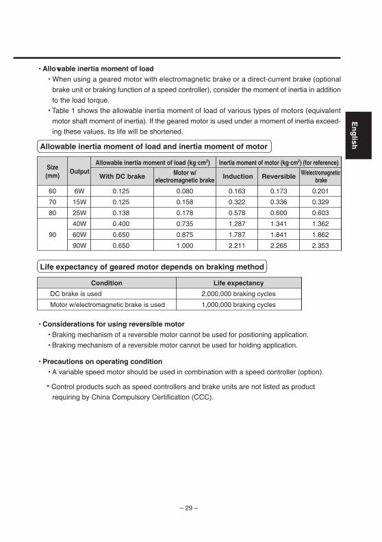
• Allowable inertia moment of load• When using a geared motor with electromagnetic brake or a direct-current brake (optional
brake unit or braking function of a speed controller), consider the moment of inertia in addition
to the load torque.
• Table 1 shows the allowable inertia moment of load of various types of motors (equivalent
motor shaft moment of inertia). If the geared motor is used under a moment of inertia exceed-
ing these values, its life will be shortened.
• Considerations for using reversible motor• Braking mechanism of a reversible motor cannot be used for positioning application.
• Braking mechanism of a reversible motor cannot be used for holding application.
• Precautions on operating condition• A variable speed motor should be used in combination with a speed controller (option).
* Control products such as speed controllers and brake units are not listed as product
requiring by China Compulsory Certification (CCC).
Size(mm) With DC brake Induction Reversible W/electromagnetic
brakeMotor w/
electromagnetic brake
60
70
80
90
Output
6W
15W
25W
40W
60W
90W
0.125
0.125
0.138
0.400
0.650
0.650
0.080
0.158
0.178
0.735
0.875
1.000
0.163
0.322
0.578
1.287
1.787
2.211
0.173
0.336
0.600
1.341
1.841
2.265
0.201
0.329
0.603
1.362
1.862
2.353
Allowable inertia moment of load (kg•cm2) Inertia moment of motor (kg•cm2) (for reference)
Allowable inertia moment of load and inertia moment of motor
DC brake is used
Motor w/electromagnetic brake is used
2,000,000 braking cycles
1,000,000 braking cycles
Condition Life expectancy
Life expectancy of geared motor depends on braking method
– 30 –
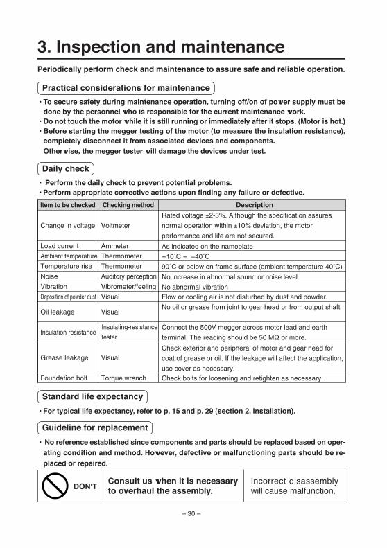
3. Inspection and maintenancePeriodically perform check and maintenance to assure safe and reliable operation.
Practical considerations for maintenance
• To secure safety during maintenance operation, turning off/on of power supply must bedone by the personnel who is responsible for the current maintenance work.
• Do not touch the motor while it is still running or immediately after it stops. (Motor is hot.)• Before starting the megger testing of the motor (to measure the insulation resistance),
completely disconnect it from associated devices and components.Otherwise, the megger tester will damage the devices under test.
Daily check
• Perform the daily check to prevent potential problems.• Perform appropriate corrective actions upon finding any failure or defective.
Item to be checked
Change in voltage
Load current
Ambient temperature
Temperature rise
Noise
Vibration
Deposition of powder dust
Oil leakage
Insulation resistance
Grease leakage
Foundation bolt
Checking method
Voltmeter
Ammeter
Thermometer
Thermometer
Auditory perception
Vibrometer/feeling
Visual
Visual
Visual
Torque wrench
Description
Rated voltage ±2-3%. Although the specification assures
normal operation within ±10% deviation, the motor
performance and life are not secured.
No oil or grease from joint to gear head or from output shaft
Connect the 500V megger across motor lead and earth
terminal. The reading should be 50 MΩ or more.
Check exterior and peripheral of motor and gear head for
coat of grease or oil. If the leakage will affect the application,
use cover as necessary.
As indicated on the nameplate
90˚C or below on frame surface (ambient temperature 40˚C)
No increase in abnormal sound or noise level
No abnormal vibrationFlow or cooling air is not disturbed by dust and powder.
Check bolts for loosening and retighten as necessary.
-10˚C - +40˚C
Insulating-resistance
tester
Standard life expectancy
• For typical life expectancy, refer to p. 15 and p. 29 (section 2. Installation).
Guideline for replacement
• No reference established since components and parts should be replaced based on oper-ating condition and method. However, defective or malfunctioning parts should be re-placed or repaired.
Consult us when it is necessaryto overhaul the assembly.DON'T
Incorrect disassemblywill cause malfunction.
– 31 –
En
glish
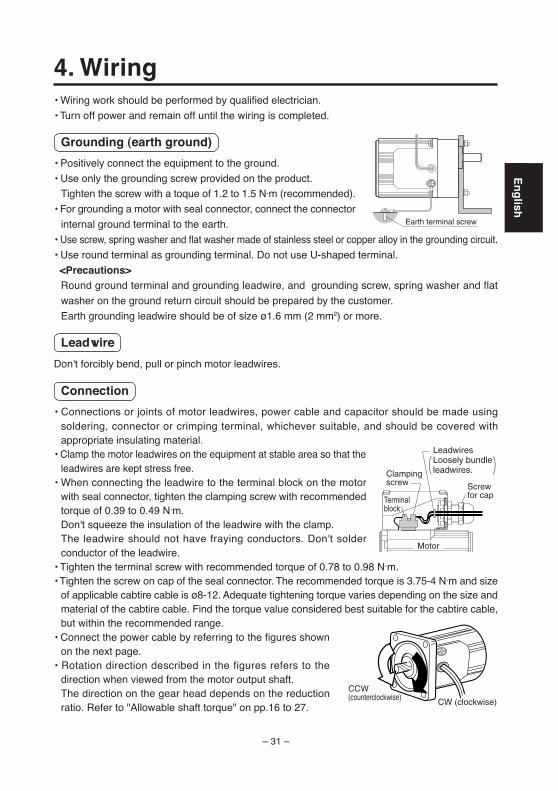
• Wiring work should be performed by qualified electrician.
• Turn off power and remain off until the wiring is completed.
Grounding (earth ground)
• Positively connect the equipment to the ground.
• Use only the grounding screw provided on the product.
Tighten the screw with a toque of 1.2 to 1.5 N·m (recommended).
• For grounding a motor with seal connector, connect the connector
internal ground terminal to the earth.
• Use screw, spring washer and flat washer made of stainless steel or copper alloy in the grounding circuit.
• Use round terminal as grounding terminal. Do not use U-shaped terminal.
<Precautions>Round ground terminal and grounding leadwire, and grounding screw, spring washer and flat
washer on the ground return circuit should be prepared by the customer.
Earth grounding leadwire should be of size ø1.6 mm (2 mm2) or more.
Leadwire
Don't forcibly bend, pull or pinch motor leadwires.
Connection
• Connections or joints of motor leadwires, power cable and capacitor should be made usingsoldering, connector or crimping terminal, whichever suitable, and should be covered withappropriate insulating material.
• Clamp the motor leadwires on the equipment at stable area so that theleadwires are kept stress free.
• When connecting the leadwire to the terminal block on the motorwith seal connector, tighten the clamping screw with recommendedtorque of 0.39 to 0.49 N·m.Don't squeeze the insulation of the leadwire with the clamp.The leadwire should not have fraying conductors. Don't solderconductor of the leadwire.
• Tighten the terminal screw with recommended torque of 0.78 to 0.98 N·m.• Tighten the screw on cap of the seal connector. The recommended torque is 3.75-4 N·m and size
of applicable cabtire cable is ø8-12. Adequate tightening torque varies depending on the size andmaterial of the cabtire cable. Find the torque value considered best suitable for the cabtire cable,but within the recommended range.
• Connect the power cable by referring to the figures shownon the next page.
• Rotation direction described in the figures refers to thedirection when viewed from the motor output shaft.The direction on the gear head depends on the reductionratio. Refer to "Allowable shaft torque" on pp.16 to 27.
4. Wiring
Earth terminal screw
CCW(counterclockwise) CW (clockwise)
Clampingscrew Screw
for cap
Motor
Terminalblock
LeadwiresLoosely bundle leadwires.
– 32 –
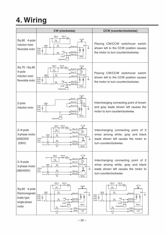
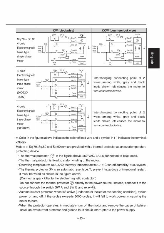
4. Wiring
Gray (U2)
Black (Z2)
Sq.60 4-pole
Induction motor
Reversible motor
2-pole
Induction motor
Sq.70 –Sq.90
4-pole
Induction motor
Reversible motor
Motor
Single-phase power source
Single-phase power source
Single-phase power source
3-phase power source
3-phase power source
Single-phase power source
Single-phase power source
CW
RyNFB
Ry
CCW
Capacitor
CW (clockwise) CCW (counterclockwise)
Placing CW/CCW switchover switch
shown left to the CCW position causes
the motor to turn counterclockwise.
Placing CW/CCW switchover switch
shown left to the CCW position causes
the motor to turn counterclockwise.
Interchanging connecting point of brown
and gray leads shown left causes the
motor to turn counterclockwise.
SW A SW B
RyRy
2-/4-pole
3-phase motor
(380/400V)
Sq.60 4-pole
Electromagnetic
brake type
single-phase
motorMotor
CW
Ry
Ry
CCW
White (U1)
Gray (U2)
Black (Z2)
Capacitor
SW A SW B
RyRy
Yellow
Yellow
Ry(Electromagnetic
brake)
Motor
CW
Ry
Ry
CCW
White (U1)
Gray (U2)
Black (Z2)
Capacitor
SW A SW B
RyRy
Yellow
Yellow
Ry
Ry Ry
(Electromagnetic brake)
White (U1)
NFB
NFB
NFB
2-/4-pole
3-phase motor
(200/220/
230V)
Interchanging connecting point of 2
wires among white, gray and black
leads shown left causes the motor to
turn counterclockwise.
Interchanging connecting point of 2
wires among white, gray and black
leads shown left causes the motor to
turn counterclockwise.
R
S
TMotor
Thermal protectorRy
Ry
Gray (V)
White (U)
Black (W)
Blue (P)
Blue (P)
Ry
SW A SW B
RyRy
P
NFB
R
N
S
TMotor
Thermal protectorRy
Ry
Gray (V)
White (U)
Black (W)
Blue (P)
Blue (P)
Ry
SW A SW B
RyRy
P
NFB
NFB
Motor
Thermal protector
CW
Ry
Ry
CCW
White (U1)
Gray (U2)
Black (Z2)
Capacitor
Blue (P)
Blue (P)
SW A SW B
RyRy
P
Motor
Thermal protectorBrown (U1)
Gray (U2)
Black (Z2)
Capacitor
Blue (P)
White (Z1) P
– 33 –
En
glish
CW (clockwise) CCW (counterclockwise)
Interchanging connecting point of 2
wires among white, gray and black
leads shown left causes the motor to
turn counterclockwise.
Interchanging connecting point of 2
wires among white, gray and black
leads shown left causes the motor to
turn counterclockwise.
Sq.70 – Sq.90
4-pole
Electromagnetic
brake type
single-phase
motor
4-pole
Electromagnetic
brake type
three-phase
motor
(380/400V)
R
N
S
T
(Electromagnetic brake)
Thermal protectorRy
Ry
Gray (V)
White (U)
Black (W)
Blue(P)
Blue(P)
Ry
SW A SW B
RyRy
P
Ry Yellow
YellowRy
Ry Yellow
YellowRy
(Electromagnetic brake)
Thermal protector
CW
Ry
Ry
CCW
Capacitor
Blue (P)
Blue (P)
SW A SW B
RyRy
P
Ry Yellow
YellowRy
(Electromagnetic brake)
Thermal protector
CW
Ry
Ry
CCW
Capacitor
Blue (P)
Blue (P)
SW A SW B
RyRy
P
Motor Motor
Motor
NFB
NFB
4-pole
Electromagnetic
brake type
three-phase
motor
(200/220/
230V)
R
S
T
(Electromagnetic brake)
Thermal protectorRy
Ry
Gray (V)
White (U)
Black (W)
Blue (P)
Blue (P)
Ry
SW A SW B
RyRy
P
Ry Yellow
YellowRy
Motor
NFB
NFBWhite (U1)
Gray (U2)
Black (Z2)
White (U1)
Gray (U2)
Black (Z2)
Single-phase power source
Single-phase power source
3-phase power source
3-phase power source
* Color in the figures above indicates the color of lead wire and a symbol in ( ) indicates the terminal.
<Note>Motors of Sq.70, Sq.80 and Sq.90 mm are provided with a thermal protector as an overtemperature
protecting device.
• The thermal protector ( in the figure above, 250 VAC, 3A) is connected to blue leads.
• The thermal protector is fixed to stator winding of the motor.
• Operating temperature: 130 ±5°C; recovery temperature: 90 ±15°C; on-off durability: 5000 cycles.
• The thermal protector is an automatic reset type. To prevent hazardous unintentional restart,
it must be wired as shown in the figure above.
(Connect a spark killer to the electromagnetic contactor.)
Do not connect the thermal protector directly to the power source. Instead, connect it to the
source through the switch SW A and SW B and relay .
• Automatic reset protector, when left active (under motor locked or overloading condition), cycles
power on and off. If the cycles exceeds 5000 cycles, it will fail to work correctly, causing the
motor to burn.
• When the protector operates, immediately turn off the motor and remove the cause of failure.
Install an overcurrent protector and ground-fault circuit interrupter to the power supply.
P
Ry
P
P
– 34 –
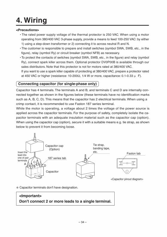
4. Wiring
AC
B D
Capacitor cap(Option)
Capacitor
187 series tab
Tie strap, banding tape,etc.Insert the
lead into one of pair terminals
<Important>Don't connect 2 or more leads to a single terminal.
<Precautions> • The rated power supply voltage of the thermal protector is 250 VAC. When using a motor
operating from 380/400 VAC 3-phase supply, provide a means to feed 100-250 VAC: by either
1) using a step-down transformer or 2) connecting it to across neutral R and N.
• The customer is responsible to prepare and install switches (symbol SWA, SWB, etc., in the
figure), relay (symbol Ry) or circuit breaker (symbol NFB) as necessary.
• To protect the contacts of switches (symbol SWA, SWB, etc., in the figure) and relay (symbol
Ry), connect spark killer across them. Optional protector DV0P00B is available through our
sales distributors. Note that this protector is not for motors rated at 380/400 VAC.
If you want to use a spark killer capable of protecting at 380/400 VAC, prepare a protector rated
at 450 VAC or higher (resistance: 10-200Ω, 1/4 W or more, capacitance: 0.1-0.33 µF).
Connecting capacitor (for single-phase only)
Capacitor has 4 terminals. The terminals A and B, and terminals C and D are internally con-
nected together as shown in the figures below (these terminals have no identification marks
such as A, B, C, D). This means that the capacitor has 2 electrical terminals. When using a
crimp contact, it is recommended to use Faston 187 series terminal.
While the motor is operating, a voltage about 2 times the voltage of the power source is
applied across the capacitor terminals. For the purpose of safety, completely isolate the ca-
pacitor terminals with an adequate insulation material such as the capacitor cap (option).
When using the capacitor cap (option), secure it with a suitable means e.g. tie strap, as shown
below to prevent it from becoming loose.
<Capacitor pinout diagram>
Faston tab
* Capacitor terminals don't have designation.
– 35 –
En
glish
5. OperationPrepare for operation
• Verify the following:
• Power is correctly connected
• Ground circuit is connected to the earth return
• Fuses and circuit breaker are at the rated capacity
• Is the terminal of capacitor positively isolated with a suitable material e.g. the capacitor cap?
• No loosen joints, connections, fasteners
• No sign of leakage of oil, grease, etc.
Trial run
• Following the successive checking, start the trial run:
(1) Without connecting load, operate the system with the motor and gear head. Check direction
and speed of turning, and for unusual vibration and noise. Then, incorporate the unit into the
application system.
(2) Turn on power. Verify smooth running of the motor and no usual sound from bearing and
gear head.
During operation
• Checking the load
• Check the amount of the current and adjust the load so that the magnitude of the conducted
current does not exceed the nameplate rating.
• When the reduction ratio of the installed gear head is 1/50 or more, the torque may exceed the
allowable shaft torque of the gear head even if the current flow rate is below the rated current.
Check if the torque is below the allowable shaft torque and adjust the load as necessary.
• Check the motor temperature rise• The motor temperature reaches a stable value by 2 or 3 hours (by 30 minutes when reversible
motor or single-phase electromagnetic brake motor) after startup.
Take into consideration the time rating.
• Keep the frame surface temperature at 90°C or below during operation at ambient temperature
40°C.
Upon occurrence of power interruption
• Turn off power switch
If the power switch is left on, the machine will operate disorderly as power is fed again, causing
possible personal injury, damage to property. Or it cannot start due to too heavy load, causing
burn out of the motor.
Do
Verify turningdirection
Wrong model or wrong wiring willcause personal injury.
– 36 –
5. OperationDuring operation
• Do not touch your body or hand to the unit to avoid burn injury. • If a failure occurs, immediately stop the operation.
Check the system and consult your local dealer.
Other precautions
• Checking starting voltageUsing a voltmeter and a variable transformer, measure the starting voltage of the assembly
incorporating the geared motor. Make sure that the voltage is lower than the value shown below.
(1) Reversible motor: 70% the rated voltage
(2) Induction motor: 80% the rated voltage
• Variable voltage causes starting error.
• Holding torque of the reversible motor varies depending on products, aged deterioration and
temperature, which cause starting error.
– 37 –
En
glish
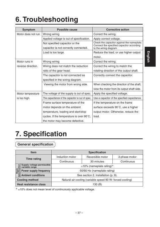
Symptom Possible cause Corrective action
Motor does not run.
Motor runs in
reverse direction.
Motor temperature
is too high.
Wrong wiring
Applied voltage is out of specification.
Not specified capacitor or the
capacitor is not correctly connected.
Load is too large.
Wrong wiring
Wiring does not match the reduction
ratio of the gear head.
The capacitor is not connected as
specified in the wiring diagram.
Viewing the motor from wrong side.
The voltage of the supply is out of spec.
The capacitance of the capacitor is out of spec.
Frame surface temperature of the
motor depends on the ambient
temperature, loading and start/stop
cycles. If the temperature is over 90˚C,
the motor may become defective.
Correct the wiring.
Apply correct voltage.
Reduce the load, or use higher output
motor.
Correct the wiring.
Correct the wiring to match the
rotating direction of the output shaft.
Correctly connect the capacitor.
When checking the direction of the shaft,
view the motor from its output shaft side.
Apply the specified voltage.
Use a capacitor of the specified capacitance.
If the temperature on the frame
surface exceeds 90˚C, use a higher
output motor. Otherwise, reduce the
load.
Check the capacitor against the nameplate. Connect the specified capacitor according to the wiring diagram.
7. Specification
6. Troubleshooting
General specification
Reversible motor
30 minutes
±10% (nameplate rating)*
50/60 Hz (nameplate rating)
See section 2. Installation (p. 9).
Natural air-cooling (variable speed 90 W: forced cooling)
130 (B)
* ±10% does not mean level of continuously applicable voltage.
Bas
ic
spec
ific
atio
n
Power supply frequency
Ambient conditions
Cooling method
Heat resistance class
Item
Time rating
Specification
Induction motor
Continuous
3-phase motor
ContinuousSupply voltage permissible variable range
– 38 –
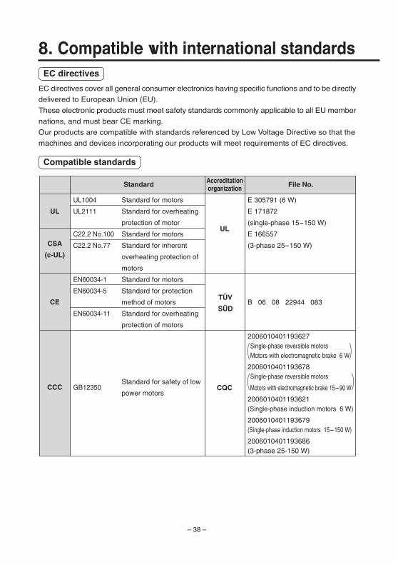
8. Compatible with international standardsEC directives
EC directives cover all general consumer electronics having specific functions and to be directly
delivered to European Union (EU).
These electronic products must meet safety standards commonly applicable to all EU member
nations, and must bear CE marking.
Our products are compatible with standards referenced by Low Voltage Directive so that the
machines and devices incorporating our products will meet requirements of EC directives.
Compatible standards
Standard for motors
Standard for overheating
protection of motor
Standard for motors
Standard for inherent
overheating protection of
motors
Standard for motors
Standard for protection
method of motors
Standard for overheating
protection of motors
Standard for safety of low
power motors
E 305791 (6 W)
E 171872
(single-phase 15-150 W)
E 166557
(3-phase 25-150 W)
B 06 08 22944 083
2006010401193627Single-phase reversible motorsMotors with electromagnetic brake 6 W
2006010401193678Single-phase reversible motors
Motors with electromagnetic brake 15-90 W
2006010401193621(Single-phase induction motors 6 W)
2006010401193679(Single-phase induction motors 15-150 W)
2006010401193686(3-phase 25-150 W)
UL
CSA
(c-UL)
CE
CCC
UL
CQC
Standard File No.Accreditationorganization
UL1004
UL2111
C22.2 No.100
C22.2 No.77
EN60034-1
EN60034-5
EN60034-11
GB12350
– 39 –
En
glish
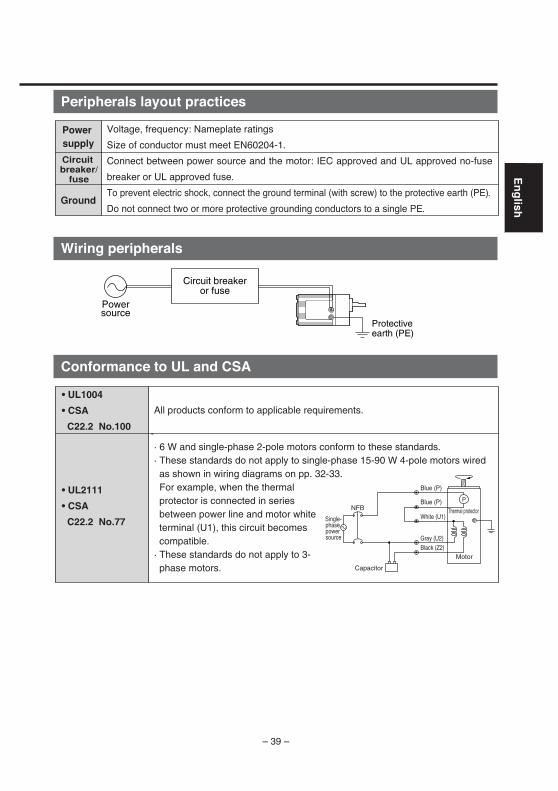
Peripherals layout practices
Wiring peripherals
Conformance to UL and CSA
! "# # $ %! & '( &
") '( &
* & $) $ +#$ #, $ & $ +-,
. # & -
Power supply
Ground
Circuit breaker/
fuse
Powersource
Protectiveearth (PE)
Circuit breakeror fuse
• UL1004
• CSA
C22.2 No.100
• UL2111
• CSA
C22.2 No.77
NFBP
All products conform to applicable requirements.
- · 6 W and single-phase 2-pole motors conform to these standards.· These standards do not apply to single-phase 15-90 W 4-pole motors wired as shown in wiring diagrams on pp. 32-33.
For example, when the thermal protector is connected in series between power line and motor white terminal (U1), this circuit becomes compatible.
· These standards do not apply to 3-phase motors.
Single-phase power source
Motor
Thermal protectorWhite (U1)
Gray (U2)Black (Z2)
Capacitor
Blue (P)
Blue (P)

– 40 –
Repair
Consult to a dealer from whom you have purchased the product for details of repair.When the product is incorporated to the machine or equipment you have purchased,consult to the manufacuter or the dealer of the machine or equipment.
Cautions for Proper Use
• This product is intended to be used with a general industrial product, but not designed or manufactured to be used in a machine or system that may cause personal death when it is failed.
• Install a safety equipments or apparatus in your application, when a serious accident or loss of property is expected due to the failure of this product.
• Consult us if the application of this product is under such special conditions and environments as nuclear energy control, aerospace, transportation, medical equipment, various safety equipments or equipments which require a lesser air contamination.
• We have been making the best effort to ensure the highest quality of the products, however, application of exceptionally larger external noise disturbance and static electricity, or failure in input power, wiring and components may result in unexpected action. It is highly recommended that you make a fail-safe design and secure the safety in the operative range.
• If the motor shaft is not electrically grounded, it may cause an electrolytic corrosion to the bearing, depending on the condition of the machine and its mounting environment, and may result in the bearing noise. Checking and verification by customer is required.
• Failure of this product depending on its content, may generate smoke of about one cigarette. Take this into consideration when the application of the machine is clean room related.
• Please be careful when using in an environment with high concentrations of sulphur or sulphuric gases, as sulphuration can lead to disconnection from the chip resistor or a poor contact connection.
• Take care to avoid inputting a supply voltage which significantly exceeds the rated range to the power supply of this product. Failure to heed this caution may result in damage to the internal parts, causing smoking and/or a fire and other trouble.
After-Sale Service (Repair)

– 41 –
En
glish
MEMO
– 42 –IMD43
S1106-0
Model No.Date ofpurchase
Dealer
Tel: ( ) -
MEMO (Fill in the blanks for reference in case of inquiry or repair.)
Motor CompanyMatsushita Electric Industrial Co., Ltd.7-1-1 Morofuku, Daito, Osaka, 574-0044, Japan Phone : +81-72-871-1212
Technical informationTechnical information of this product (Instruction Manual, CAD data) can be downloadedfrom the following web site. http://industrial.panasonic.com/ww/i_e/25000/motor_fa_e/motor_fa_e.html