instruction manual combi english english combi condensate ... · english instruction manual combi 2...
TRANSCRIPT

Instruction manual Combi English
1
English CombiCondensate Pump
3004046

English Instruction manual Combi
2
Introduction 02
General information 02
Important safety notice 02
Technical data 03
Product description 04
Transport and storage 06
Commissioning 06
Maintenance 16
Return and disposal 17
Troubleshooting 17
Replacement parts 18
Appendix 18
Introduction
Thank you for purchasing our all new Combi condensate pump. The Combi has been completely redesigned retaining all the good features you like and upgrading everything else. Its digital water sensor, universal voltage and user configurable flow ensure it is the strongest, quietest under A/C mounted condensate pump on the market today.
General information
REFCO products have been specially designed and manufactured for use by trained refrigeration and air-conditioning service en-gineers only. REFCO explicitly states that their products must only be sold to professionally trained service engineers.
These operating instructions contain important information about handling the Combi. Safe operation of the device requires adheren-ce to all safety instructions and operating guidelines.
- The local safety regulations applicable to the area in which the Combi is being used should also be adhered to, along with gene-ral safety guidelines.
- The operating instructions are part of the product and should be stored in close proximity to the Combi where they should be readily accessible to qualified personnel at all times.
- The qualified personnel must have carefully read and under-stood the operating instructions prior to operating the device.
- The manufacturer shall not be liable for any damage whatsoever arising through improper use, failure to comply with these ope-rating instructions, assignment of inadequately qualified person-nel, or unauthorised modification of the Combi.
- The general terms and conditions as set out in the sales docu-mentation shall apply.
Symbols and writing standards
WARNING/CAUTION An appropriate safety instruction should be followed or caution to a potential hazard exists.
DANGEROUS VOLTAGE To indicate hazards arising from dangerous voltages.
Please read all safety and installation instructions
completely before commencing.
For indoor use only.
The identify electrical equipment designed primarily for indoor use
Waste of Electrical and Electronic Equipment (WEEE) Do not throw the pump in domestic waste
CE compliant
Certification mark that indicates conformity with health, safety and environmental protection standart for products
ETL recognized component This product has been tested and meets the applicable published standart for North America and Canada
RoHS compilant
Regulatory Compliance Mark (RCM)
Compliant with the electrical safety requirements of Australia and New Zealand
Safety instructions
Please read all safety and installation instructions
completely before commencing. To prevent any risk only certified and appropriately trained staff with sufficient technical training and tools shall install this pro-duct. Product installation and electrical connections both require professional training for safe installation and correct product operation.
Save these instructions for further reference.
For indoor use only. To identify electrical equipment
designed primarly for indoor use. Not submersible.
The Combi condensate pump is to be installed in accordance with local and regional electrical codes.
WARNING: Disconnect all electrical power before starting
installation, maintenance, or service work.
WARNING: Disconnect electrical power before removing
and checking internal fuse.
CAUTION: Do not install the REFCO condensate pump if
there are any signs of damage.
WARNING: Check the cables REFCO condensate pump
power and alarm cords prior to, during and periodically for signs of damage. If either the power or alarm cords
are damaged, isolate and disconnect the condensate pump from service. Contact REFCO for a replacement.
The Combi combined power/alarm cable lead-out is non-re-
placeable. lf this is damaged the entire pump must be replaced.
WARNING: The REFCO condensate pump cables should
not be cut, and should be routed so that they cannot be damaged during and after installation.
CAUTION: All tubing connections are to be secured in place on the barb connections using self-locking cable tie-wraps.
DO NOT use tools to connect the tubing.
DO NOT operate this product in ambient temperatures below 5 °C (41 °F).
Contents

Instruction manual Combi English
3
DO NOT operate with incoming water above a temperature of 40 °C (104 °F).
CAUTION: Do not allow any chemicals to come in contact with this condensate pump. Please remove the pump and water sensor before using any coil cleaning solutions and other chemi-cals. Flush the evaporator coils with water before reinstalling the condensate pump and water sensor.
Ensure the coils are chemical free before reinstallation.
CAUTION: In all installations where any property damage and or personal injury may result from an inoperative, failed, incorrectly
Technical data
Maximum flow rate: 42 l/Hr. (11 GPH)
Maximum suction: 3 m (9.80 ft.) self priming
Maximum head: 20 m (65.60 ft.)
Maximum horizontal run: 100 m (330 ft.) at 0 head and 0 suction
Sound: 20dBA at 1 m DIN EN ISO 3741:2011 / DIN EN ISO 3744:2010
Voltage: 100 ~ 240 VAC 50/60 Hz auto sensing universal power input
Power: 8 watts during maximum operation at 110v
Alarm relay: 10 Amps NO or NC contacts with integrated replaceable 10A fuse 5 × 20 mm
Weight: 1‘000 g (2.2 Lbs.)
Discharge star tube: 6.25 mm I.D. (1/4“) × 1 m (3.3 ft.)
Packaging dimensions: 250 x 340 x 54 mm (9.9 x 13.4 x 2.1 inches)
Bulk pack dimensions: 10 Pcs dimensions are 590 x 265 x 365 mm (23.2 x 10.4 x 14.4 inches)
Color: RAL #7040 Grey and RAL #1023 Yellow
Protection: Class II double insulation, fully potted, IP-44
Operation temp: Ambient 3°C to 40°C (37.5°F to 104°F) / Water 5°C to 25°C (41°F to 77°F)
Compliance: Conforms to UL: 778 and certified to CSA C22.2 #68
Power cable 11 must not be entered with a tensile load.
Alarm cable 12 and power cable must be completely pressed into the jack.
Only use the original power cable 11 and alarm cable 12.
0 2 4 6 8 10 12 14 16 18 20 22 24 26 28 30 32 34 36 38 40 42 44
0 1 2 3 4 5 6 7 8 9 10
Capacity l/Hr
Capacity US G/Hr
Vert
ical
lift
/ he
ad p
ress
ure
m
20
18
16
14
12
10
8
6
4
2
0
Gobi II & Combi at full power
60
50
40
30
20
10
0
Vert
ical
lift
/ he
ad p
ress
ure
ft.
Cappacity
0 2 4 6 8 10 12 14 16 18 20 22 24 26 28 30 32 34 36 38 40 42 44
0 1 2 3 4 5 6 7 8 9 10
Capacity l/Hr
Capacity US G/Hr
Vert
ical
lift
/ he
ad p
ress
ure
m
20
18
16
14
12
10
8
6
4
2
0
Gobi II & Combi at full power
60
50
40
30
20
10
0
Vert
ical
lift
/ he
ad p
ress
ure
ft.
installed or leaking condensate pump, it is strongly recommended that the alarm relay shall be used in fail-safe mode to completely shut down the air conditioning unit, should a pump failure occur.

English Instruction manual Combi
4
1 2 3 4 5
7 8 9
6
Product description
Provided accessories
Diagnostic LEDUSB portDip-switchesWater sensor plugPump body Factory-installed fuse Digital sensor Replacable filterWater sensor
Das Gobi II Kit beinhaltet
Combi Kit beinhaltet
Mitgeliefertes Zubehör
Mitgeliefertes Zubehör
Installationsvideo auf www.condensate-pumps.com Benutzerhandbuch zum Download auf www.condensate-pumps.com
Abmessungen der Pumpe
1 Diagnose-LED2 USB-Anschluss3 Dip-Schalter
4 Stecker Wassersensor5 Pumpenkörper6 Werkseitig installierte
Sicherung
7 Digitaler Sensor8 Austauschbarer Filter9 Sensorgehäuse
21
6
7
8
3 4 5
10
9
7
6
5421 3
8
9
1 Pumpenkörper2 Werkseitig installierte
Sicherung3 Austauschbarer Filter4 Digitaler Sensor5 Wasserbehälter6 Dip-Schalter7 USB-Anschluss8 Diagnose-LED9 Wandrückenplatte
10 Abdeckung
Abmessungen der Pumpe Abmessungen Wassersensor
48mm 39mm
41mm
42mm
15mm
48mm 39mm132mm 87mm
53mm
53mm
286mm
Stromversorgungskabel
Sternschlauch und Siphon- Stopp-Vorrichtung
Saugschlauch Lüftungsschlauch
Werkseitig instal-lierte Sicherung
Alarmkabel
Kabelbinder
Sensorkabel
Stromversorgungskabel
Sternschlauch und Siphon- Stopp-Vorrichtung
Werkseitig installierte Sicherung
Ankerschraube rot
Alarmkabel
Schrauben
Kabelbinder
Dimensions pump
Power cable Type: SJT/AWM 2103, 2x18 AWG, 105 oC, VW-1Part No. 3004008
11
1.54 inches
1.6 inches
1.6 inches
15mm
1.89 inches 1.54 inches5.47 inches 3.43 inches
2.09 iches
2.09 inches
11.26 inches
1.89 inches
Alarm cablePart No. 3004006
12
1.54 inches
1.6 inches
1.6 inches
15mm
1.89 inches 1.54 inches5.47 inches 3.43 inches
2.09 iches
2.09 inches
11.26 inches
1.89 inches
Star tube and Stop-Siphon device Part No. 3004065
14
1.54 inches
1.6 inches
1.6 inches
15mm
1.89 inches 1.54 inches5.47 inches 3.43 inches
2.09 iches
2.09 inches
11.26 inches
1.89 inches
Alarm relay HR 10A fuse, 5x20mm Part No. 3004050
15
1.54 inches
1.6 inches
1.6 inches
15mm
1.89 inches 1.54 inches5.47 inches 3.43 inches
2.09 iches
2.09 inches
11.26 inches
1.89 inches
17
1.54 inches
1.6 inches
1.6 inches
15mm
1.89 inches 1.54 inches5.47 inches 3.43 inches
2.09 iches
2.09 inches
11.26 inches
1.89 inches
Cable ties, 3 pcs.
Sensor cable Part No. 3004007
10
1.54 inches
1.6 inches
1.6 inches
15mm
1.89 inches 1.54 inches5.47 inches 3.43 inches
2.09 iches
2.09 inches
11.26 inches
1.89 inches
Suction tube Part No. 3004034
13
1.54 inches
1.6 inches
1.6 inches
15mm
1.89 inches 1.54 inches5.47 inches 3.43 inches
2.09 iches
2.09 inches
11.26 inches
1.89 inches
Vent tube Part No. 3004033
16
1.54 inches
1.6 inches
1.6 inches
15mm
1.89 inches 1.54 inches5.47 inches 3.43 inches
2.09 iches
2.09 inches
11.26 inches
1.89 inches
18
Wire nut Indoor use only
123456789
Instruction manual Combi English
5
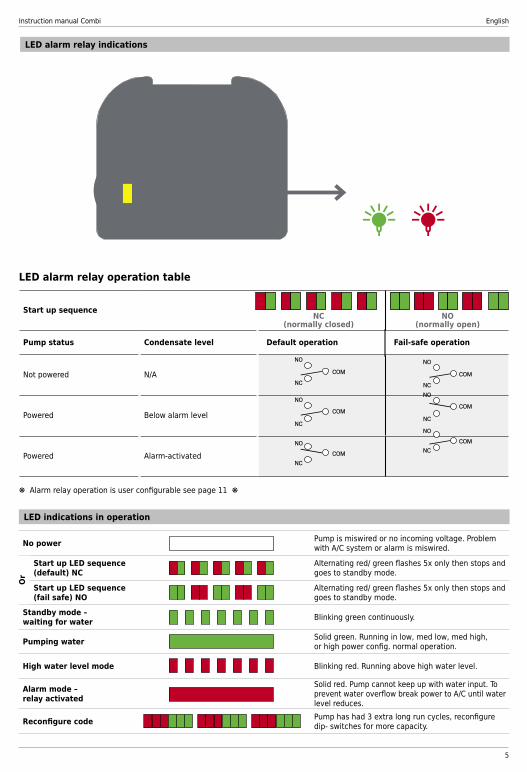
LED alarm relay indications
LED indications in operation
Start up sequence
Pump status Condensate level Default operation Fail-safe operation
Not powered N/A
Powered Below alarm level
Powered Alarm-activated
NC(normally closed)
NO(normally open)
No power Pump is miswired or no incoming voltage. Problem with A/C system or alarm is miswired.
Start up LED sequence (default) NC
Alternating red/ green flashes 5x only then stops and goes to standby mode.
Start up LED sequence (fail safe) NO
Alternating red/ green flashes 5x only then stops and goes to standby mode.
Standby mode – waiting for water Blinking green continuously.
Pumping water Solid green. Running in low, med low, med high, or high power config. normal operation.
High water level mode Blinking red. Running above high water level.
Alarm mode –relay activated
Solid red. Pump cannot keep up with water input. To prevent water overflow break power to A/C until water level reduces.
Reconfigure code Pump has had 3 extra long run cycles, reconfigure dip- switches for more capacity.
Or
LED alarm relay operation table
❋ Alarm relay operation is user configurable see page 11 ❋

English Instruction manual Combi
6
lowup to 18K Btu/h (5.3kW)
medium lowup to 42K Btu/h(12kW)
medium highup to 72K Btu/h(21.1kW)
highup to 120K Btu/h(35kW)
ON
1 2
ON
1 2
ON
1 2
ON
1 2Ratings for air conditioning units
Factory default
The rating of the condensate pump has to be adjusted according to the power of the conditioning unit.
Transport and storage
TransportInspect the Combi for any potential transportation damage. Any obvious damage should be reported to the vendor immediately.
Storage- Storage temperature: -20 °C to +60 °C- Humidity: 0 to 90% relative humidity (no condensation)
Commissioning
Application
PH#2
Water sensor in the AC unit, pump in the ceiling
ON
1 2
Water sensor inside the AC unit and pump outside the unit
Water sensor and pump in the AC unit next to each other
Water sensor vertical and pump in the AC unit
Water sensor can be usedhorizontally or vertically.
Tools needed

Instruction manual Combi English
7
Water sensor inside the AC unit and pump outside the unit
1
1
2
1a 1bHorizontal installation Vertical installation
2a
12
Horizontal installation
1211
Remove plug and install vent tube.
Leave silicone plug in water sensor.

English Instruction manual Combi
8
2b
1
Vertical installation
1211

Instruction manual Combi English
9
3
1211

English Instruction manual Combi
10
4
Examples are for reference only.
1112
WARNING: Disconnect all electrical power before starting installation, maintenance, or service work.
Installations only made by qualified people.
Plug connections have to be completely dry.
INPUT POWER: 100-240V, 50/60Hz, 2.5A (Max)
The alarm relay fuse must be rated for the specific application and of the HR type, 5 x 20mm 250 VAC, 10A (Max)

Instruction manual Combi English
11
3
Evaporator units (indoor)
VRF / VRV condenser unit (outdoor)
Utility power
When multi-split system is installed (drawing # 2)
Power up LED flash sequence
Pump status Condensate level NC defaultoperation
NO fail-safeoperation
Unpowered or (pump failure)
n/a
Powered Below alarm level
Powered Alarm activated
NC
NO
COM
NC
NO
COM
Alarm relay operation table
NC
NO
COM
NC
NO
COM
NC
NO
COM
NC
NO
COM
1. Unplug pump 2. Move dip-switch positions to 3. Plug pump in
4. Wait for one green LED blink 5. Move dip-switch positions to 6. Wait for one red LED blink 7. Reset dip-switch positions to 8. Wait for one green LED blink 9. Unplug pump 10. Set the dip-switches back to the desired capacity configuration. (Low, medium-low, medium-high, high) 11. Plug pump in and check that power up LED sequence matches the desired alarm relay operation 12. Done!
When indoor evaporator unit is powered from the outdoor condenser unit (drawing # 1)
Pump for indoor
use only COM
Repl
acea
ble
fuse
10A
Condenser unit (outdoor)
Data (communications)
Earth (ground)
Neutral (live 2)
100-240vac (live 1)
Evaporator unit (indoor)
NC
NO
Utility power
**O
RAN
GE
VIO
LET
GRE
Y
BRO
WN
BLU
E
Alarm relay
NO NC COM L N
N
L
3 3 N L
NC = Normally closed relay NO = Normally open relay To use fail-safe operation. 1. Remove the violet wire from indoor connection and isolate with wire nut. 2. Connect the orange wire to the same indoor connection. 3. Change alarm relay to fail-safe operation
N
L
BROWN
BLUE
COM NC
NO
Alarm relay
N
3
N
Alarm safety circuit
Repl
acea
ble
fuse
10A
N Neutral (live 2)
100-240vac (live 1)
Earth (ground)
Data
L
L L
N
NO NC COM
To reset alarm relay to default (NC) operation repeat steps 1 thru 11
L
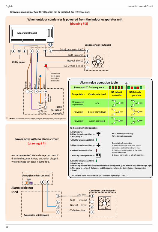
Below are examples of how REFCO pumps can be installed. For reference only.
To change alarm relay operation
Pump for indoor use only
Or
Connection made inside the indoor evaporator
VIO
LET
**O
RAN
GE
GRE
Y *
** ORANGE: Isolate with wire nut or tape during NC (normally closed) default operation
** ORANGE: Isolate with wire nut or tape during NC (normally closed) default operation
English Instruction manual Combi
12
When outdoor condenser is powered from the indoor evaporator unit (drawing # 3)
Pump for indoor
use only
COM
Repl
acea
ble
fuse
10A
Condenser unit (outdoor)
Data (communications)
Earth (ground)
Neutral (live 2)
100-240vac (live 1)
NC
NO
Utility power
Alarm Relay
NO NC COM L N
N
L
3 3 N L N L
Below are examples of how REFCO pumps can be installed. For reference only.
Condenser unit (outdoor)
3 3 Data line
Earth (ground)
Neutral (live 2)
100-240vac (live 1) 1
2
1
2
Evaporator unit (indoor)
1 2
Power only with no alarm circuit (drawing # 4)
Not recommended: Water damage can occur if drain line becomes kinked, pinched or plugged. Water damage can occur if pump fails.
Pump (for indoor use only)
Alarm cable not used
Connection made inside the indoor evaporator
Evaporator (Indoor)
Power up LED flash sequence
Pump status Condensate level NC default operation
NO fail-safe operation
Unpowered or (pump failure)
n/a
Powered Below alarm level
Powered Alarm activated
NC
NO
COM
NC
NO
COM
Alarm relay operation table
NC
NO
COM
NC
NO
COM
NC
NO
COM
NC
NO
COM
1. Unplug pump 2. Move dip-switch positions to 3. Plug pump in
4. Wait for one green LED blink 5. Move dip-switch positions to 6. Wait for one red LED blink 7. Reset dip-switch positions to 8. Wait for one green LED blink 9. Unplug pump 10. Set the dip-switches back to the desired capacity configuration. (Low, medium-low, medium-high, high) 11. Plug pump in and check that power up LED sequence matches the desired alarm relay operation 12. Done!
NC = Normally closed relay NO = Normally open relay To use fail-safe operation. 1. Remove the violet wire from indoor connection and isolate with wire nut. 2. Connect the orange wire to the same indoor connection. 3. Change alarm relay to fail-safe operation
To reset alarm relay to default (NC) operation repeat steps 1 thru 11
To change alarm relay operation
Or
*
**O
RAN
GE
VIO
LET
GRE
Y
BRO
WN
BLU
E
** ORANGE: Isolate with wire nut or tape during NC (normally closed) default operation
Instruction manual Combi English
13
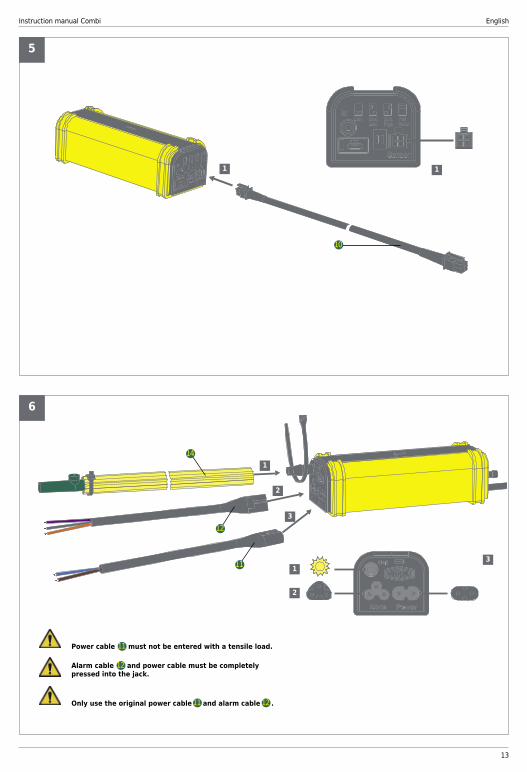
1 1
5
1
1
2
2
3
3
6
11
12
14
10
Power cable must not be entered with a tensile load.
Alarm cable and power cable must be completely pressed into the jack.
Only use the original power cable and alarm cable .
11
12
11 12

English Instruction manual Combi
14
7a
1
2
Horizontal installation
to drain
1/4˝ I.D. (6mm)(Field supplied)

Instruction manual Combi English
15
7b
1
2
Vertical installation
to d
rain
1/4˝I.D. (6mm)(Field supplied)

English Instruction manual Combi
16
Change alarm fuse
1
2
3
15
Water filter maintenance Regular cleaning / replacement of the Combi water filter will help to prolong the life of the pump. The sole purpose of the water filter is to prevent foreign debris from entering the pump itself. The time period between filter service can only be determined from the specific environment in which the pump is installed. We recommend cleaning or replacing the water filter a minimum of every 12 months. However, when installed in environments with high dust, smoke, cooking oils or the possibility of algae growth it is recommended to clean or replace the filter every 3 months. To clean / replace the water filter, simply remove it from the water sensor body and thoroughly wash with cold water and replace in between the two interior sensor body retaining flanges as shown below.
Maintenance
The alarm relay fuse must be rated for the specific application and of the HR type, 5 x 20 mm 250VAC, 10A (MAX)
Installations only made by qualified people.
WARNING: Disconnect all electrical power before starting installation, maintenance, or service work.
At the end of useful life of the condensate pump send the product to the separate collection for electric and electronic devices. (According to local regulations)
Return and disposal
Instruction manual Combi English
17
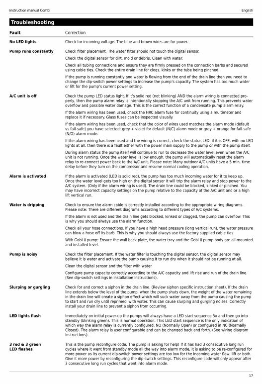
Fault Correction
No LED lights Check for incoming voltage. The blue and brown wires are for power.
Pump runs constantly Check filter placement. The water filter should not touch the digital sensor. Check the digital sensor for dirt, mold or debris. Clean with water. Check all tubing connections and ensure they are firmly pressed on the connection barbs and secured using cable ties. Check the entire drain line for clogs, kinks or the tube being pinched. If the pump is running constantly and water is flowing from the end of the drain line then you need to change the dip-switch power settings to increase the pump’s capacity. The system has too much water or lift for the pump’s current power setting.
A/C unit is off Check the pump LED status light. If it’s solid red (not blinking) AND the alarm wiring is connected pro- perly, then the pump alarm relay is intentionally stopping the A/C unit from running. This prevents water overflow and possible water damage. This is the correct function of a condensate pump alarm relay. If the alarm wiring has been used, check the HRC alarm fuse for continuity using a multimeter and replace it if necessary. Glass fuses can be inspected visually. If the alarm wiring has been used, check that the color of wires used matches the alarm mode (default vs fail-safe) you have selected: grey + violet for default (N/C) alarm mode or grey + orange for fail-safe (N/O) alarm mode. If the alarm wiring has been used and the wiring is correct, check the status LED; if it is OFF, with no LED lights at all, then there is a fault either with the power main supply to the pump or with the pump itself. During alarm status the pump itself will continue to run to decrease the water level even when the A/C unit is not running. Once the water level is low enough, the pump will automatically reset the alarm relay to re-connect power back to the A/C unit. Please note: Many outdoor A/C units have a 5 min. time delay before they turn on the compressor and resume normal cooling operation.
Alarm is activated If the alarm is activated (LED is solid red), the pump has too much incoming water for it to keep up. Once the water level gets too high on the digital sensor it will trip the alarm relay and stop power to the A/C system. (Only if the alarm wiring is used). The drain line could be blocked, kinked or pinched. You may have incorrect capacity settings on the pump relative to the capacity of the A/C unit and or a high lift vertical run.
Water is dripping Check to ensure the alarm cable is correctly installed according to the appropriate wiring diagrams. Please note: There are different diagrams according to different types of A/C systems. If the alarm is not used and the drain line gets blocked, kinked or clogged, the pump can overflow. This is why you should always use the alarm function. Check all your hose connections. If you have a high head pressure (long vertical run), the water pressure can blow a hose off its barb. This is why you should always use the factory supplied cable ties. With Gobi II pump: Ensure the wall back plate, the water tray and the Gobi II pump body are all mounted and installed level.
Pump is noisy Check the filter placement. If the water filter is touching the digital sensor, the digital sensor may believe it is water and activate the pump causing it to run dry when it should not be running at all. Clean the digital sensor and the filter with water. Configure pump capacity correctly according to the A/C capacity and lift rise and run of the drain line. (See dip-switch settings in installation instructions).
Slurping or gurgling Check for and correct a siphon in the drain line. (Review siphon specific instruction sheet). If the drain line extends below the level of the pump, when the pump shuts down, the weight of the water remaining in the drain line will create a siphon effect which will suck water away from the pump causing the pump to start and run dry until reprimed with water. This can cause slurping and gurgling noises. Correctly install your drain line to prevent a siphon from occurring.
LED lights flash Immediately on initial power-up the pumps will always have a LED start sequence 5x and then go into standby (blinking green). This is normal operation. This LED start sequence is the only indication of which way the alarm relay is currently configured. NO (Normally Open) or configured in NC (Normally Closed). The alarm relay is user configurable and can be changed back and forth. (See wiring diagram instructions).
3 red & 3 green This is the pump reconfigure code. The pump is asking for help! If it has had 3 consecutive long run LED flashes cycles where it went from standby mode all the way into alarm mode, it is asking to be re-configured for more power as its current dip-switch power settings are too low for the incoming water flow, lift or both. Give it more power by reconfiguring the dip-switch settings. This reconfigure code will only appear after 3 consecutive long run cycles that went into alarm mode.
Troubleshooting

English Instruction manual Combi
18
Replacement parts and accessories
HSG-4065/4Stop-Siphon Device, 4 pcs.Part No 3004065
FUS-4050/10Fuses 5x20 10A, 10 pcs.Part No 3004050
PVC-TUBEPlastic tube 6 mm (1⁄4”), minimum 30 metersPart No 4679160
FIL-4063/4Filter, 4 pcs.Part No 3004063
KIT-4087Star tube with Stop-Siphon devicePart No 3004087
Conversion formula for US Gallons/Hr:
_________ L/Hr. x 0.264 = _________ G/Hr.
A
BC
A B CTotal Length (Run) Meters
Suction (lift) Discharge (Rise) m 5 10 15 20 30
0.0 m
0 42 42 40 40 401 (3.3ft.) 42 42 40 40 363 (9.9 ft.) 37 37 35 35 345 (16.4 ft.) 31 30 29 29 2910 (32.8 ft.) 17 16 15 14 1415 (49.2 ft.) 9 9 9 9 820 (65.6 ft.) 8 7
1.0 m (3.3 Ft)
0 42 42 42 40 401 (3.3ft.) 42 42 42 40 393 (9.9 ft.) 36 36 35 35 345 (16.4 ft.) 30 30 29 29 2910 (32.8 ft.) 16 16 16 16 1515 (49.2 ft.) 10 10 10 10 1020 (65.6 ft.) 7 9
2.0 m (6.6 Ft.)
0 35 35 35 35 341 (3.3ft.) 33 33 33 32 313 (9.9 ft.) 33 32 31 31 305 (16.4 ft.) 27 26 26 26 2510 (32.8 ft.) 17 17 16 16 1515 (49.2 ft.) 10 10 10 9 920 (65.6 ft.) 5 5
3.0 m (9.9 Ft.)
0 30 30 30 30 291 (3.3ft.) 28 28 28 28 273 (9.9 ft.) 28 28 28 27 265 (16.4 ft.) 23 23 23 23 2210 (32.8 ft.) 15 15 15 15 1515 (49.2 ft.) 7 7 6 5 5
Corrected flow based on installation L/Hr. 1/4” (6mm) discharge tube @ full power
Appendix

Instruction manual Combi English
19

REFCO Manufacturing Ltd.Industriestrasse 116285 Hitzkirch - Switzerland
Telefon +41 41 919 72 82Telefax +41 41 919 72 83
17/3
4125