instruction manual - alfa laval - · pdf file1 ec declaration of conformity the designated...
TRANSCRIPT

ESE03056-EN3 2017-03
Original manual
Instruction Manual
ALTB-SB-20


Table of contents
The information herein is correct at the time of issue but may be subject to change without prior notice
1. EC Declaration of Conformity .. . . . . . . . . . . . . . . . . . . . . . . . . . . . . . . . . . . . . . . . . . . . . . . . . . . . . . . . . . . . . . . . . . . . . . 4
2. Safety ... . . . . . . . . . . . . . . . . . . . . . . . . . . . . . . . . . . . . . . . . . . . . . . . . . . . . . . . . . . . . . . . . . . . . . . . . . . . . . . . . . . . . . . . . . . . . . . . . . 52.1. Important information .. . . . . . . . . . . . . . . . . . . . . . . . . . . . . . . . . . . . . . . . . . . . . . . . . . . . . . . . . . . . . . . . . . . . . . . . . . . . 52.2. Warning signs .. .. . . . . . . . . . . . . . . . . . . . . . . . . . . . . . . . . . . . . . . . . . . . . . . . . . . . . . . . . . . . . . . . . . . . . . . . . . . . . . . . . . 52.3. Intended use .. . .. . . . . . . . . . . . . . . . . . . . . . . . . . . . . . . . . . . . . . . . . . . . . . . . . . . . . . . . . . . . . . . . . . . . . . . . . . . . . . . . . . 52.4. Safety precautions .. . .. . . . . . . . . . . . . . . . . . . . . . . . . . . . . . . . . . . . . . . . . . . . . . . . . . . . . . . . . . . . . . . . . . . . . . . . . . . . 6
3. Installation .. . . . . . . . . . . . . . . . . . . . . . . . . . . . . . . . . . . . . . . . . . . . . . . . . . . . . . . . . . . . . . . . . . . . . . . . . . . . . . . . . . . . . . . . . . . . . 73.1. Unpacking/delivery . . .. . . . . . . . . . . . . . . . . . . . . . . . . . . . . . . . . . . . . . . . . . . . . . . . . . . . . . . . . . . . . . . . . . . . . . . . . . . . 73.2. Requirement for installation, personnel . .. . . . . . . . . . . . . . . . . . . . . . . . . . . . . . . . . . . . . . . . . . . . . . . . . . . . . . . 83.3. Installation (with cutting/machining and welding required) . . . . . . . . . . . . . . . . . . . . . . . . . . . . . . . . . . . . . 83.4. Installation (assembling) . . .. . . . . . . . . . . . . . . . . . . . . . . . . . . . . . . . . . . . . . . . . . . . . . . . . . . . . . . . . . . . . . . . . . . . . . . 123.5. Installation, electrically . . . . . . . . . . . . . . . . . . . . . . . . . . . . . . . . . . . . . . . . . . . . . . . . . . . . . . . . . . . . . . . . . . . . . . . . . . . . 19
4. Operation ... . . . . . . . . . . . . . . . . . . . . . . . . . . . . . . . . . . . . . . . . . . . . . . . . . . . . . . . . . . . . . . . . . . . . . . . . . . . . . . . . . . . . . . . . . . . . 204.1. Operation .. .. . . . . . . . . . . . . . . . . . . . . . . . . . . . . . . . . . . . . . . . . . . . . . . . . . . . . . . . . . . . . . . . . . . . . . . . . . . . . . . . . . . . . . . 204.2. Inspection ... . . . . . . . . . . . . . . . . . . . . . . . . . . . . . . . . . . . . . . . . . . . . . . . . . . . . . . . . . . . . . . . . . . . . . . . . . . . . . . . . . . . . . . 204.3. Troubleshooting .. . . . . . . . . . . . . . . . . . . . . . . . . . . . . . . . . . . . . . . . . . . . . . . . . . . . . . . . . . . . . . . . . . . . . . . . . . . . . . . . . . 204.4. Cleaning .. . .. . . . . . . . . . . . . . . . . . . . . . . . . . . . . . . . . . . . . . . . . . . . . . . . . . . . . . . . . . . . . . . . . . . . . . . . . . . . . . . . . . . . . . . 21
5. Maintenance .. . .. . . . . . . . . . . . . . . . . . . . . . . . . . . . . . . . . . . . . . . . . . . . . . . . . . . . . . . . . . . . . . . . . . . . . . . . . . . . . . . . . . . . . . . 225.1. General Maintenance .. . . . . . . . . . . . . . . . . . . . . . . . . . . . . . . . . . . . . . . . . . . . . . . . . . . . . . . . . . . . . . . . . . . . . . . . . . . . 225.2. Disassembling of agitator .. . . . . . . . . . . . . . . . . . . . . . . . . . . . . . . . . . . . . . . . . . . . . . . . . . . . . . . . . . . . . . . . . . . . . . . 225.3. Replacement of gear motor . . . .. . . . . . . . . . . . . . . . . . . . . . . . . . . . . . . . . . . . . . . . . . . . . . . . . . . . . . . . . . . . . . . . . 225.4. Replacement of seals . . . . . . . . . . . . . . . . . . . . . . . . . . . . . . . . . . . . . . . . . . . . . . . . . . . . . . . . . . . . . . . . . . . . . . . . . . . . 225.5. Replacement of Bearing for bottom console . .. . . . . . . . . . . . . . . . . . . . . . . . . . . . . . . . . . . . . . . . . . . . . . . . . 22
6. Technical Data ... . . . . . . . . . . . . . . . . . . . . . . . . . . . . . . . . . . . . . . . . . . . . . . . . . . . . . . . . . . . . . . . . . . . . . . . . . . . . . . . . . . . . . . 23
7. Parts list / Service kits . . . .. . . . . . . . . . . . . . . . . . . . . . . . . . . . . . . . . . . . . . . . . . . . . . . . . . . . . . . . . . . . . . . . . . . . . . . . . . . . 247.1. ALTB-SB-20-AE (with aeration) . . . . . . . . . . . . . . . . . . . . . . . . . . . . . . . . . . . . . . . . . . . . . . . . . . . . . . . . . . . . . . . . . 247.2. ALTB-SB-20 (without aeration) .. . . . . . . . . . . . . . . . . . . . . . . . . . . . . . . . . . . . . . . . . . . . . . . . . . . . . . . . . . . . . . . . . 267.3. ALTB-SB-20 (with and without aeration) . . . . . . . . . . . . . . . . . . . . . . . . . . . . . . . . . . . . . . . . . . . . . . . . . . . . . . . 277.4. Mounting Tools . .. . . . . . . . . . . . . . . . . . . . . . . . . . . . . . . . . . . . . . . . . . . . . . . . . . . . . . . . . . . . . . . . . . . . . . . . . . . . . . . . . . 367.5. Installation Drawings ... . . . . . . . . . . . . . . . . . . . . . . . . . . . . . . . . . . . . . . . . . . . . . . . . . . . . . . . . . . . . . . . . . . . . . . . . . . . 38
8. Appendix ... . . . . . . . . . . . . . . . . . . . . . . . . . . . . . . . . . . . . . . . . . . . . . . . . . . . . . . . . . . . . . . . . . . . . . . . . . . . . . . . . . . . . . . . . . . . . 418.1. Declaration of Compliance .. . . . . . . . . . . . . . . . . . . . . . . . . . . . . . . . . . . . . . . . . . . . . . . . . . . . . . . . . . . . . . . . . . . . . . 418.2. Order specific “Tank With Agitator” drawing, example ... . . . . . . . . . . . . . . . . . . . . . . . . . . . . . . . . . . . . . 428.3. WPS .... . . . . . . . . . . . . . . . . . . . . . . . . . . . . . . . . . . . . . . . . . . . . . . . . . . . . . . . . . . . . . . . . . . . . . . . . . . . . . . . . . . . . . . . . . . . . 438.4. Drive unit lubrication ... . . . . . . . . . . . . . . . . . . . . . . . . . . . . . . . . . . . . . . . . . . . . . . . . . . . . . . . . . . . . . . . . . . . . . . . . . . . 448.5. Drive unit instruction ... . . . . . . . . . . . . . . . . . . . . . . . . . . . . . . . . . . . . . . . . . . . . . . . . . . . . . . . . . . . . . . . . . . . . . . . . . . . 49
3

1 EC Declaration of Conformity
The Designated Company
Alfa Laval Kolding A/SCompany Name
Albuen 31, DK-6000 Kolding, DenmarkAddress
+45 79 32 22 00Phone No.
hereby declare that
ALTB-SBDesignation
20Type
is in conformity with the following directive with amendments:
Machinery Directive 2006/42/ECFDA 21CFR§177Regulation (EC) 1935/2004
The person authorised to compile the technical file is the signer of this document.
Global Product Quality Manager, Pumps, Valves, Fittings and Tank Equipment Lars Kruse AndersenTitle Name
Kolding 2017-03-01Place Date Signature
(This Declaration of Conformity replaces Declaration of Conformity dated 2015-06-02)
4

2 Safety
Unsafe practices and other important information are emphasized in this manual.Warnings are emphasized by means of special signs.
2.1 Important information
Always read the manual before using the agitator!
WARNINGIndicates that special procedures must be followed to avoid serious personal injury.
CAUTIONIndicates that special procedures must be followed to avoid damage to the agitator.
NOTEIndicates important information to simplify or clarify procedures.
2.2 Warning signs
General warning:
Caustic agents:
Dangerous electric voltage:
2.3 Intended use
- The Agitator in only for mixing / conditioning / stirring of liquids in a tank.- The Agitator is only made for top mounting position on the top plate / welding flange on the tank.
5

2 Safety
All warnings in the manual are summarised on this page.Pay special attention to the instructions below so that serious personal injury and/or damage to the valve are avoided.
2.4 Safety precautions
2.4.1 Installation:Always read the technical data thoroughly (see 6 Technical Data).Always follow installation instructions thoroughly (see 3 Installation).Never expose the Agitator to undue vibrations or shocks.Never start the Agitator in the wrong direction of rotation.Ensure that the tank media is not corrosive to the Agitator.Only install the Agitator in environments within temperature limit: -20°C and +40°C.Only install the Agitator in altitudes less than 1000 m above sea level.Only use authorized personnel when electrically equipment is connected.
2.4.2 Operation:Always read the technical data thoroughly (see 6 Technical Data).Never start Agitator in the wrong direction of rotation.Beware of Agitator in operation can produce sound levels in excess of 85dB(A).Always handle lye and acid with great care.Always rinse well with clean water after cleaning.Never run the agitator for a longer time (seconds) without product, water or cleaning liquid in the tank.
2.4.3 Maintenance:Always follow the maintenance instruction thoroughly (see 5 Maintenance.)Always follow the maintenance instruction for gear motor thoroughly (see 8.5 Drive unit instruction).Always study the parts list and assembly drawing carefully (see 7 Parts list / Service kits).Never touch the moving parts while the Agitator is connected to the power supply.Always disconnect the power supply while servicing the Agitator.Ensure correct rotation direction of propeller before startup and after any maintains there might have impact onthe direction.Never service the agitator or tank with product or cleaning liquid in the tank.
6

3 Installation
The instruction manual is part of delivery. Study the instructions carefully.The Agitator is for permanent fastening.Make sure the motor corresponds to the environment.Check the direction of rotation before operation.
3.1 Unpacking/delivery
Always use lifting equipment when handling the agitator.Alfa Laval cannot be responsible for incorrect unpacking.Step 13.1.1 Inspect the delivery for visible transportation damage (crates and packaging) - all issues should be reported to carrier.
Step 23.1.2 Check that deliveries are according to delivery notes.Complete Agitators can be delivered in more than one shipment.Agitators can be delivered as one of the following:1. Agitator parts and instruction manual required for tank builder to install shafts and propellers.2. Agitator parts and instruction manual required for tank builder to install drive unit (gear motor) and sealing system.3. As 1) and 2) in one shipment.
Step 33.1.3 Inspect Agitator parts for visible transport damage.
Step 4
3.1.4 Do NOT use eye bolts on gear motor to lift the Agitator. They are only for gear motor removal.
Step 53.1.5 During lifting:- Always support the shaft adequately to protect shaft and bearings.- Be carefully not to damage shaft-end with treads.- Never expose the Agitator to undue vibrations or shocks.- Control for oil leakage on gears – leave vent plug in gear until gear is installed and in correct position.
Figure 1, un-activated vent plug
7

3 Installation
The instruction manual is part of delivery. Study the instructions carefully.The Agitator is for permanent fastening.Make sure the motor corresponds to the environment.Check the direction of rotation before operation.
3.2 Requirement for installation, personnel
Welder:Experience from similar types of installation, covering TIG, MIG and MAG welding procedures in stainless steel thinwalled material.Proven skills in reading installation guidelines and drawings ensuring that the installation is carried out safe for personneland property.
Erectors:
Experience from similar types of installation.Proven skills in reading installation guidelines and drawings ensuring that the installation is carried out safe for personneland property.
Electrician:
Certified according to local regulations and experience from similar types of installation.Proven skills in reading installation guidelines and drawings ensuring that the installation is carried out safe for personneland property.
3.3 Installation (with cutting/machining and welding required)
3.3.1 Requirement for installationThis work should be carried out by at least two persons and for safety reasons a platform or a scaffold should beestablished around the tank top.During installation ensure to use sufficient lightning.The tank top must be horizontally during installation – if that is not the case, a laser must be used to ensure that theright position for the “Bottom Console” can be found.
Ensure that the tank does not contain neither dangerous liquid nor gasses and that good ventilation is established.Always have safety elements removed by authorized personnel.Never cover or remove nameplates.Always use lifting equipment when handling heavy parts of the Agitator.
Never connect to power during installation.Always have the Agitator connected to power supply by authorized personnel.Note: Alfa Laval highly recommends installing motor protection guard to the Agitator.All position numbers and item numbers refer to the drawings show and specified in 7 Parts list / Service kits
8

3 Installation
The instruction manual is part of delivery. Study the instructions carefully.The Agitator is for permanent fastening.Make sure the motor corresponds to the environment.Check the direction of rotation before operation.
Step 13.3.2See illustration in 7.5.1 page 38.A. The three “Adjustable Leg For Bottom Console” pos. 70 are fastened to the “Bottom Console for Agitator” pos. 74 using
the three “Screw” pos. 77.B. The assembled “Bottom Console” from a)
“Guide spindle for bearing” pos. 69“Tool – Bushing” pos. 83,“Tool – Back stop” pos. 85,“Screw” pos. 91,“Propeller” pos. 73,“Agitator Shaft” pos. 71 (if delivered),“Propeller” pos. 72 (if delivered),“Agitator Shaft” pos. 75,are lowered into the tank and assembled. In some cases all the parts can be assembled outside the tank and lowered intothe tank assembled. All threads must be greased to ensure not to damage the threads.
C. According to the order specific drawing "Agitator with Tank" that comes with the manual (not in the manual) the correctAgitator position is selected (0/125/175 mm off center) which specify which position of holes to be used (data in thismanual are not to be used – find order specific drawing).Example of an order specific drawing "Order specific "Tank With Agitator" drawing, example" are to be found in 8.2, page 42.
D. Mount the “Tool Guide Plate” pos. 80 on the “Tank mounting flange” pos. 99 letting the shaft pos. 75 entering the correcthole in pos. 80. The “Tool Guide Plate” must be fastened to the tank top using two diagonally located holes in the tank top.
E. Mount the “Tool – Top Guide” pos. 82 to the “Tool Guide Plate” pos. 80 using the four “Screw” pos. 88.F. Mount the “Tool – Top Guide” pos. 81 into the “Tool – Top Guide” pos. 82.G. Rotate / orientate pos. 82 enabling the “Screw” pos. 90 to be used to fasten the shaft in vertical direction during adjustment
of the “Bottom Console” pos. 74.
9

3 Installation
The instruction manual is part of delivery. Study the instructions carefully.The Agitator is for permanent fastening.Make sure the motor corresponds to the environment.Check the direction of rotation before operation.
Step 23.3.3 See illustration in 7.5.1 page 38.A. If the tank top is horizontally within 0,5° the gravity can be used
as guideline for position of the “Bottom Console” – if it is notpossible to adjust the tank top to horizontally position (withinthe tolerance) a laser pointer must be used to ensure that theright position for the “Bottom Console” is found.
B. The Agitator is lifted to the correct position as shown on theorder specific drawing “Tank with Agitator” that comes withthe manual (not in the manual).Example of an order specific drawing "Order specific "TankWith Agitator" drawing, example" are to be found in 8.2, page42. The “Screw” pos. 90 is tightened (not more than sufficient)to fasten the shafts in vertical position.
C. When the agitator shaft is in correct position the three“Adjustable Leg For Bottom Console” pos. 70 areadjusted/rotated facing the tank bottom and the three “Screws”pos. 77 are fastened. If the legs on “Bottom Console forAgitator” pos. 74 are too long they are cut to the requiredlength.
D. Tag weld the three “Adjustable Leg For Bottom Console” pos.70 to the tank bottom using TIG welding.
E. Untighten the “Screw” pos. 90 ensure that the shaft can rotatefreely.
F. Tighten the screw again.G. Remove one “Screw” pos. 77 and fill the thread hole with
welding, continue one by one with the two other screws.H. Remove the “Screw” and pos. 90.I. Verify that the shaft can rotate freely.J. Grind the welded seams to the required finish.
Figure 2, Height of Bottom Console
Figure 3, Tightening screws
Figure 4, Welding Bottom Console
10

3 Installation
The instruction manual is part of delivery. Study the instructions carefully.The Agitator is for permanent fastening.Make sure the motor corresponds to the environment.Check the direction of rotation before operation.
Step 33.3.4 See illustration and Parts List in 7.5.1 and 7.5.3.
A. Using a permanent pen do a marking line at position 1 asshown on 7.5.1. page 38 on the shaft pos. 75.
B. Verify that the line is at the same vertical position as theupper surface of the tank top flange (welding flange) pos.99.
C. Remove the “Tool” parts pos. 88, 82, 81, 80.D. Using the equation: X1 = “Thickness of Gasket, pos. 101” +
“Thickness of Top Plate, pos. 100”, mark the cutting line 2.e.g:Thickness of Gasket = 5 mmThickness of Top Plate = 20 mmX1 = 5 + 20 = 25 mif an O-ring is used as gasket the “Thickness of Gasket” = 0
E. The “Agitator Shaft” is delivered longer than needed andshould be shortened to no more than 300 mm. If it must beshortened more, the inside diameter must be machined tofit the “Shaft, Upper for Agitator” pos. 76 outer diameterwithin a 0,1 mm tolerance.
F. Cut the “Agitator Shaft” pos. 75 at the cutting line 2.G. Press the “Shaft, Upper for Agitator” pos. 76 onto the
“Agitator Shaft” pos. 75 firmly and ensure that it is alignedwith the shaft.
H. Weld it as shown on 7.5.1 page 38 and in WPS in 8.3,page 43.
I. Grind the welded seams to the required finish.
Figure 5, Marking of pos. 1
Step 43.3.5
A. Unscrew and disassembly the shafts and propeller unit – label all the parts carefully with item number and tank number.B. Arrange careful transportation of the tank and the agitator parts to the destination.
11

3 Installation
The instruction manual is part of delivery. Study the instructions carefully.The Agitator is for permanent fastening.Make sure the motor corresponds to the environment.Check the direction of rotation before operation.
3.4 Installation (assembling)
3.4.1 Mounting of O-Rings in generalA. Apply some food-approved grease to the O-ring
Figure 6, Greasing O-ring
B.Press the O-ring into the appropriated groove at position 0°and 180°
Figure 7, Inserting O-ring
C.Press the O-ring into the appropriated groove at position 90°and 270°
Figure 8, Inserting O-ring
12

3 Installation
The instruction manual is part of delivery. Study the instructions carefully.The Agitator is for permanent fastening.Make sure the motor corresponds to the environment.Check the direction of rotation before operation.
Step 53.4.2 See illustrations, 7.1, 7.2, and 7.5.3.
A. Mount the “Bearing For Bottom Console” pos. 25 into the “Bottom Console” pos. 74.B. Clean all shafts, propellers and Guide Spindel (pos. 69) threads for grease.C. Assemble the shaft and propeller unit inside the tank with gaskets, o-rings and Loctite®: pos. 24, 30, 35, 69, 71, 72, 73, 75,
76 and slide it carefully down/into the “Bottom Console pos. 74” with the “Bearing For Bottom Console” pos. 25.D. Avoid hard bumping against the bottom console bearing.E. Tighten all threads till 100-200 Nm.F. Mount the “Gasket” pos. 101 and the “Top Plate” pos. 100 – tight with a couple of screws.G. Press the “Spray Ball Bearing” pos. 26 into the “Spray ball”, pos. 8.H. Mount the “Spray ball” pos. 8 (incl. the “Spray ball Bearing” pos. 26) onto the “Tube, CIP for Spray Ball” pos. 3 using the
“Spring lock for spray ball” pos. 9I. In some cases all the parts can be assembled outside the tank and lowered into the tank assembled.J. Insert the “O-Ring” pos. 33 into the “Tube, CIP for Spray Ball” pos. 3.K. Position the “Tube, CIP for Spray Ball” pos. 8 onto the “Top Flange” pos. 100.
13

3 Installation
The instruction manual is part of delivery. Study the instructions carefully.The Agitator is for permanent fastening.Make sure the motor corresponds to the environment.Check the direction of rotation before operation.
Step 63.4.3 If without Aeration go to Step 7.If with Aeration continue below:See illustrations, 7.1, 7.2, and 7.5.3.
A. Position the “Spring guide” pos. 7B. Press in the “Pressure spring” pos. 6 on the “Aeration seal box” pos. 27 and insert the two “O-rings” pos. 34 and 36
using some food approved grease.C. Add some food-approved grease to the shaft pos. 76 and slide the parts on the shaft and position them as shown below.
14

3 Installation
The instruction manual is part of delivery. Study the instructions carefully.The Agitator is for permanent fastening.Make sure the motor corresponds to the environment.Check the direction of rotation before operation.
Step 73.4.4 See illustrations, 7.1, 7.2, and 7.5.3.
A. Press in the two “Guide Pin” pos. 13 into the “Console for Agitator”, pos. 4.B. Press in the two “O-ring” pos. 31 and pos. 32 into pos. 4.C. Mount the “Console for Agitator”, pos. 4 on the “Tube, CIP for Spray Ball” pos. 3.D. Using the appropriate screws and Loctite®, the four washers pos. 22 and four nuts pos. 21 are sequentially tightened
to about 200 Nm.
15

3 Installation
The instruction manual is part of delivery. Study the instructions carefully.The Agitator is for permanent fastening.Make sure the motor corresponds to the environment.Check the direction of rotation before operation.
Step 83.4.5 See illustrations, 7.1, 7.2, and 7.5.3.The Mechanical seal pos. 28 (28.1, 28.2, 28.3, 28.4, 28.5, 28.6) consist of several parts as labelled below – the parts cannot beordered separately – only as one complete mechanically seal pos. 28.
A. Add some food-approved grease to the O-ring pos. 28.2 and mount it on the stationary seal ring pos. 28.1.B. Press both parts (pos. 28.1 and pos. 28.2) into the “Flange, Upper” pos. 5.C. Add some food-approved grease to the O-ring pos. 28.4 and slides the parts pos. 28.3, 28.4, 28.6 and 28.5 onto the shaft.D. Mount the “Flange, Upper” pos. 5 onto the “Console for Agitator” pos. 4 – ensure that it is positioned rotation-wise
as required.E. Press in the two “Guide Pin” pos. 12.F. Add some Loctite® to the four screws pos. 19, mount them with the “Washers” pos. 16 and tighten the screws sequentially
to 51 Nm.G. Mount the “Parallel Key” pos. 78 using the “Screw” pos. 79.
Figure 9, Greasing 28.4
Figure 11, 28.1 and 28.2
Figure 10, 28.1, 28.1 and 5
16

3 Installation
The instruction manual is part of delivery. Study the instructions carefully.The Agitator is for permanent fastening.Make sure the motor corresponds to the environment.Check the direction of rotation before operation.
Step 93.4.6 See illustrations, 7.1, 7.2, and 7.5.3.
A. The shaft-end surface pos. 76 and the hollow shaft surface of the gear motor pos. 2 are cleaned and gently greased.B. The gear motor pos. 2 is gently lowered onto the “Flange, Upper” pos. 5 using a hoist.C. The screws pos. 15, washers pos. 16 and nuts pos. 20 are mounted using some Loctite® and tightened till 51 Nm.
17

3 Installation
The instruction manual is part of delivery. Study the instructions carefully.The Agitator is for permanent fastening.Make sure the motor corresponds to the environment.Check the direction of rotation before operation.
D. The washer pos. 18 consists of two parts attached to each other with some silicone as shown on the picture. It is importantthat the parts are positioned as shown.
E. The bushing that follows the gear motor seen on the picture is used to fasten the shaft into the gear motor.
Figure 13, One washer pos. 22 Figure 12, Bushing for shaft / gear motor
F. The screw pos. 17 is tightened (without using Loctite®) to 51 Nm.G. The cover that follows the gear motor is mounted on the gear motor covering the shaft and bushing and tightened.H. The oil vent plug is activated on the gear motor (see below and 8.5 “Drive Unit Instructions”).
Figure 14, Activation of gear vent plug
I. Use of gear motor covers is not permitted due to risk of reduced cooling on motor.J. Verify that the distance between “Bearing for bottom Console” pos. 25 top and the lower part of “Guide spindle for bearing”
pos. 69 is about 15 mm as shown below and 7.5.3 “Complete Agitator In Tank”.
Figure 15, Installation verification
18

3 Installation
The instruction manual is part of delivery. Study the instructions carefully.The Agitator is for permanent fastening.Make sure the motor corresponds to the environment.Check the direction of rotation before operation.
3.5 Installation, electrically
- Operation by unauthorized personnel may endanger personnel and property.- Treat all electrical equipment as powered.- Switch off the power before maintenance and repair.
- The electrician must be certified according to local regulations and with at least 3 years’ experience from similar types ofinstallations.
- The electrician must have proven skills in reading and working from drawings and cable lists.- The electrician must have knowledge of local safety regulations for power and automation and making sure that any work
carried out is safe for personnel and property before the equipment is put back into operation.
If you need assistance or have questions – please contact Alfa Laval.
- The motor requires the power supply as indicated on the name plate.- It is recommended to secure the motor with a motor protection.- We recommend starting the motor by use of a soft starter with a start ramp up time of 2-7.5 sec.- We recommend installation of a service switch at the agitator to secure the personnel during service work.- Perform a visual inspection of the direction of rotation. The direction required is indicated on the name plate.
- Rotation of agitator must be clockwise. Otherwise the agitator will be damaged.
19

4 Operation
Study the instructions carefully and pay special attention to warnings! Always check the Agitator before operation. Alfa Lavalrecommends a soft starter for the Agitator to reduce the load on tank and Agitator.
4.1 Operation
Rotation of agitator must always be clockwise.Use of gear motor covers is not permitted due to risk of reduced cooling on motor.
If batch rotation is observed during operation, the optimum effect of the agitator is achieved by interval agitation. If intervalagitation is used, the gear motor must be installed with a soft-starter to increase gear motor life time and reduce forces on thetank system.
If a sensitive product is processed, agitation speed and time should be reduced as much as possible.If the agitator is equipped with an aeration valve, it is possible to aerate the product through the shaft during the agitation.
4.2 Inspection
Part Inspection IntervalGear motor- Clean surfaces to avoid overheating- Check for oil leakages
MonthlyMonthly
Sealing- Verify that the seals are not leaking MonthlyBottom console bearing- Check for wear – radial movement < 5 mm Semi-annually
4.3 Troubleshooting
Problem Cause/result RemedyNot startingGear motor - Defect - Dismantle gear motor, check for
correct rotation- Replace gear motor
- Fault at power supply - Check power supply connection- Check voltage and frequency
correspond with motor name plate- Check frequency converter adjustment
correspond with motor name plateAgitator - Obstructed - Check that Agitator can rotate freely
without striking anythingVibrationsGuidance - Bottom Console Bearing - Change Bearing / BushingPropeller - Damaged
- Unbalanced- Contact Alfa Laval- Clean propeller
Shaft - Damaged - Contact Alfa LavalUnusual soundsGuidance - Shaft rotation – radial movement > 5 mm - Change Bearing / BushingLeakageGear motor - Oil leakage
- CIP fluid or other from drain- Renovate or change gear motor- Replace sealing
Performance- Deviation from normal operation - Operation must be according to
specification
20

4 Operation
Study the instructions carefully and pay special attention to warnings! Always check the Agitator before operation. Alfa Lavalrecommends a soft starter for the Agitator to reduce the load on tank and Agitator.
4.4 Cleaning
4.4.1 General Information
The agitator is fitted with a rotating spray ball designed to clean agitator and tank as part of the same process.
The agitator does not require a special cleaning procedure but the process can be integrated in the usual tank cleaningconcept. However, hot caustic cleaning is always recommended.
The Agitator must not be run at temperatures above 70° C.
Ensure that all surfaces in contact with product are totally clean so product is not contaminated.
Pay special attention to:
- Impeller device surfaces.- Surfaces between propellers and shaft.- Surfaces around sealing and bushings.- Surfaces around weldings.
4.4.2 Cleaning examples- Pre-rinse with cold water for approximately 3 minutes.- The caustic cleaning step should be made with hot caustic 60-70°C 30 - 45 minutes.- The yeast mixer should be running continuously during CIP.- The recommended CIP flow rate is 20-25 m3/h at an inlet pressure of:
- Without aeration: 2,0 bar (2 bar above tank pressure).- With aeration: 3-3,5 bar (3-3,5 bar above tank pressure).
- The cleaning should be made as soon as possible after emptying the tank, while the inside surfaces are still wet.- Hot water for approximately 3 minutes.- Cold water for approximately 3 minutes.- If the installation has steam or hot water above 70° C the agitator must be turned off.
21

5 Maintenance
Ensure totally clean surfaces during mounting. Always use original Alfa Laval parts.
5.1 General Maintenance
- Maintenance of the Agitator should only be performed by authorized personnel.- For maintenance instructions of gear motor please see 8.5 “Drive Unit Instruction”.- Ensure totally clean surfaces during maintenance.- For lifting instruction, please see 3 Installation.- Always disconnect the power supply when servicing the Agitator.- Always use proper tools.- Always replace worn sealing elements before reassembling.- Follow the dismantling and assembly instructions to the letter.- All scrap must be stored/disposed of in accordance with current rules and directives.- Always use original Alfa Laval spare parts.
Part Replace everySealing 3000 hours or 2nd yearBearing for bottom console (pos. 25) 3000 hours or 2nd year
5.2 Disassembling of agitator
Follow 3.4.2 - 3.4.6 in reverse order.
5.3 Replacement of gear motor
See 3.4.6.
5.4 Replacement of seals
See 3.4.3 - 3.4.5.
5.5 Replacement of Bearing for bottom console
The complete agitator must be lifted using a hoist and the bearing for bottom console pos. 25 can be changed.
22

6 Technical Data
Ensure totally clean surfaces during mounting. Always use original Alfa Laval parts.
Environmental requirements:Temperature: 10°C - 40°CRelative humidity: 20% - 80%
Size:See order confirmation / delivery note: Dimensions to be found in 7 Parts list / Service kits
Power supply:See order confirmation / delivery note: Data to be found in 7.3.13 Parts list Service kits, Gear Motor,
Variants.
CIP:Temperature: < 70°C, recommended about 65°CPressure: Without aeration: 2,0 bar (2 bar above tank pressure)
With aeration: 3-3,5 bar (3-3,5 bar above tank pressure)Quantity: 20-25 m3/hDetergent: Suitable for: steel EN 1.4404, PTFE, PVDF and EPDM
Aeration (sterile air):Pressure: 1 bar (1 bar above tank pressure)Quantity: 0-100 l/min
Material:See order confirmation / delivery note: Data to be found in 7 Parts list / Service kits
23

7 Parts list / Service kits
Ensure totally clean surfaces during mounting. Always use original Alfa Laval parts.
7.1 ALTB-SB-20-AE (with aeration)
7.1.1 Drawing (item number 9614313201)
24

7 Parts list / Service kits
Ensure totally clean surfaces during mounting. Always use original Alfa Laval parts.
7.1.2 Part list (item number 9614313201):Pos.No.
Qty. Item No. DrawingNo.
Denomination Materials Total weight [kg]
1 1 See table ondrawing
96143142 Shaft, Propeller and Bottom console, type 20 See assembly
2 1 See table ondrawing
96143133 Gearmotor for type 20 NA
3 1 See table ondrawing
96143085 Tube, CIP for spray ball 1,4404
4 1 9614307901 96143079 Console for Agitator, Welded 1,44045 1 9614308301 96143083 Flange, Upper for Agitator 1,44046 1 9614311401 96143114 Pressure spring 1 bar 1,4317 1 9614309101 96143091 Spring guide, Agitator type 20 1,44048 1 9614309301 96143093 Spray ball Ø94-2T, Ø63,5 1,44049 1 9614308901 96143089 Spring lock for spray ball 1,440410 1 9614312001 96143120 Union 1,440111 1 9614311201 96143112 Plug for 2" and 3" P.E 1,4307/1,430112 2 9614313502 96143135 Guide Pin A213 2 9614313501 96143135 Guide Pin A214 1 TE26010415604156 Name plate AISI 304L15 4 TE2601000017None Screw A216 8 TE2601000346None Washer A217 1 TE2601000328None Screw A218 1 TE2601000166None Washer A219 4 TE2601000208None Screw A220 4 TE2601000355None Cap nut A221 4 TE2601000058None Cap nut A222 4 TE2601000348None Washer A223 4 TE2601000202None Rivet A224 1 9614314101 96143141 Loctite® 2701, 10 ml NA25 1 9614311001 96143110 Bearing for bottom console PTFE AF 1022 /
Acoflon 80926 1 9614309201 96143092 Spray ball bearing PVDF27 1 9614309001 96143090 Aeration seal box PTFE AF 1111 /
Acoflon 80228 1 9614311301 96143113 Mechanical seal EN 12756: GBEGG29 1 9614311801 96143118 Gasket PA (Nylon)30 4 9614311802 96143118 Gasket PTFE31 1 9614312706 96143127 O-ring EPDM32 1 9614312707 96143127 O-ring EPDM33 1 9614312704 96143127 O-ring EPDM34 1 9614312702 96143127 O-ring EPDM35 4 9614312701 96143127 O-ring EPDM36 1 9614312708 96143127 O-ring EPDM
18
7.1.3 Spare Part Kit:Spare Part Kit item number 9614313202 includes parts pos. #24 to #36
25

7 Parts list / Service kits
Ensure totally clean surfaces during mounting. Always use original Alfa Laval parts.
7.2 ALTB-SB-20 (without aeration)
7.2.1 Drawing (item number 9614311901):As shown on 7.1.1 “ALTB-SB-20 (with aeration)” but without part no: 6, 7, 27, 34 and 36.
7.2.2 Part list (item number 9614311901):As shown on 7.1.2 “ALTB-SB-20 (with aeration)” but without part no: 6, 7, 27, 34 and 36.
7.2.3 Spare Part Kit:Spare Part Kit item number 9614311902 includes parts pos. #24 to #36 except part no: 27, 34 and 36 which is not part ofthe agitator.
26
7 Parts list / Service kits
Ensure totally clean surfaces during mounting. Always use original Alfa Laval parts.
7.3 ALTB-SB-20 (with and without aeration)
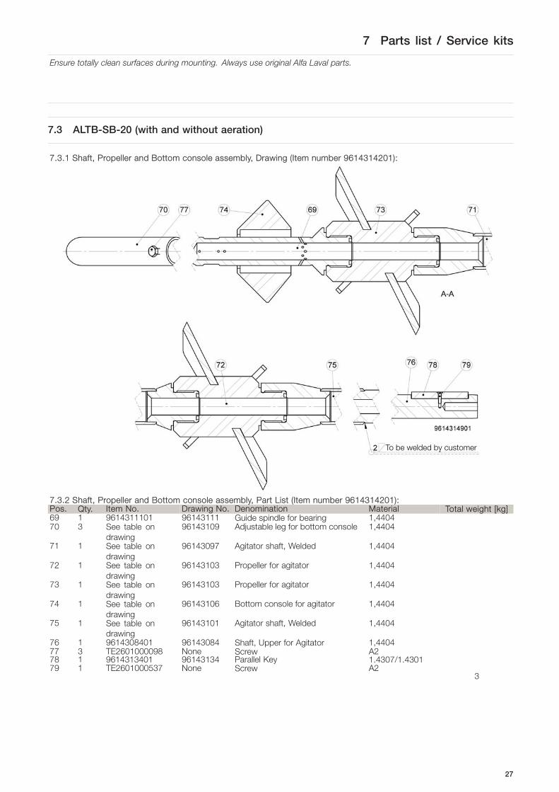
7.3.1 Shaft, Propeller and Bottom console assembly, Drawing (Item number 9614314201):
To be welded by customer
7.3.2 Shaft, Propeller and Bottom console assembly, Part List (Item number 9614314201):Pos. Qty. Item No. Drawing No. Denomination Material Total weight [kg]69 1 9614311101 96143111 Guide spindle for bearing 1,440470 3 See table on
drawing96143109 Adjustable leg for bottom console 1,4404
71 1 See table ondrawing
96143097 Agitator shaft, Welded 1,4404
72 1 See table ondrawing
96143103 Propeller for agitator 1,4404
73 1 See table ondrawing
96143103 Propeller for agitator 1,4404
74 1 See table ondrawing
96143106 Bottom console for agitator 1,4404
75 1 See table ondrawing
96143101 Agitator shaft, Welded 1,4404
76 1 9614308401 96143084 Shaft, Upper for Agitator 1,440477 3 TE2601000098 None Screw A278 1 9614313401 96143134 Parallel Key 1.4307/1.430179 1 TE2601000537 None Screw A2
3
27

7 Parts list / Service kits
Ensure totally clean surfaces during mounting. Always use original Alfa Laval parts.
7.3.3 Adjustable leg for bottom console, Drawing(Drawing number 9614324109):
7.3.4 Adjustable leg for bottom console, Variants(Drawing number 9614324109):Item No. Drawing No. Y / [°] Total
weight[kg]
9614310901 96143109 90,09614310902 96143109 87,59614310903 96143109 85,09614310904 96143109 82,59614310905 96143109 80,09614310906 96143109 77,59614310907 96143109 75,09614310908 96143109 72,59614310909 96143109 70,09614310910 96143109 67,59614310911 96143109 65,09614310912 96143109 62,59614310913 96143109 60,0
0,3
28

7 Parts list / Service kits
Ensure totally clean surfaces during mounting. Always use original Alfa Laval parts.
7.3.5 Agitator shaft, welded, Drawing (Drawing number 96143097):
7.3.6 Agitator shaft, welded, Variants (Drawing number 96143097):Item No. Drawing No. L / [mm] Weight [kg]9614309701 96143097 500 29614309702 96143097 600 29614309703 96143097 700 39614309704 96143097 800 39614309705 96143097 900 39614309706 96143097 1000 39614309707 96143097 1100 49614309708 96143097 1200 49614309709 96143097 1300 49614309710 96143097 1400 59614309711 96143097 1500 59614309712 96143097 1600 59614309713 96143097 1700 59614309714 96143097 1800 69614309715 96143097 1900 69614309716 96143097 2000 69614309717 96143097 2100 69614309718 96143097 2200 79614309719 96143097 2300 79614309720 96143097 2400 79614309721 96143097 2500 7
29

7 Parts list / Service kits
Ensure totally clean surfaces during mounting. Always use original Alfa Laval parts.
7.3.7 Propeller, Drawing (Drawing number 96143103):
7.3.8 Propeller, Variants (Drawing number 96143103):Item No. Drawing No. Ø Propeller / [mm] Weight [kg]9614310301 96143103 296 49614310302 96143103 345 49614310303 96143103 394 59614310304 96143103 444 59614310305 96143103 493 69614310306 96143103 543 69614310307 96143103 593 69614310308 96143103 643 79614310309 96143103 692 79614310310 96143103 742 89614310311 96143103 792 89614310312 96143103 842 99614310313 96143103 892 99614310314 96143103 942 99614310315 96143103 992 109614310316 96143103 1042 10
30

7 Parts list / Service kits
Ensure totally clean surfaces during mounting. Always use original Alfa Laval parts.
7.3.9 Bottom Console for Agitator, Drawing (Drawing number 96143106):
7.3.10 Bottom Console for Agitator, Variants (Drawing number 96143106):Item No. Drawing
No.Leg 1(mm)
Leg 2(mm)
Leg 3(mm)
Weight[kg]
Item No. Drawing No. Leg 1(mm)
Leg 2(mm)
Leg 3(mm)
Weight[kg]
9614310601 96143106 200 200 200 4 9614310642 96143106 700 700 600 99614310602 96143106 300 300 200 5 9614310643 96143106 800 800 600 109614310603 96143106 400 400 200 5 9614310644 96143106 900 900 600 119614310604 96143106 500 500 200 6 9614310645 96143106 1000 1000 600 129614310605 96143106 600 600 200 7 9614310646 96143106 200 200 700 69614310606 96143106 700 700 200 8 9614310647 96143106 300 300 700 79614310607 96143106 800 800 200 9 9614310648 96143106 400 400 700 79614310608 96143106 900 900 200 9 9614310649 96143106 500 500 700 89614310609 96143106 1000 1000 200 10 9614310650 96143106 600 600 700 99614310610 96143106 200 200 300 4 9614310651 96143106 700 700 700 109614310611 96143106 300 300 300 5 9614310652 96143106 800 800 700 119614310612 96143106 400 400 300 6 9614310653 96143106 900 900 700 119614310613 96143106 500 500 300 7 9614310654 96143106 1000 1000 700 129614310614 96143106 600 600 300 7 9614310655 96143106 200 200 800 69614310615 96143106 700 700 300 8 9614310656 96143106 300 300 800 79614310616 96143106 800 800 300 9 9614310657 96143106 400 400 800 89614310617 96143106 900 900 300 10 9614310658 96143106 500 500 800 99614310618 96143106 1000 1000 300 11 9614310659 96143106 600 600 800 99614310619 96143106 200 200 400 5 9614310660 96143106 700 700 800 109614310620 96143106 300 300 400 5 9614310661 96143106 800 800 800 119614310621 96143106 400 400 400 6 9614310662 96143106 900 900 800 129614310622 96143106 500 500 400 7 9614310663 96143106 1000 1000 800 139614310623 96143106 600 600 400 8 9614310664 96143106 200 200 900 79614310624 96143106 700 700 400 9 9614310665 96143106 300 300 900 79614310625 96143106 800 800 400 9 9614310666 96143106 400 400 900 89614310626 96143106 900 900 400 10 9614310667 96143106 500 500 900 99614310627 96143106 1000 1000 400 11 9614310668 96143106 600 600 900 109614310628 96143106 200 200 500 5 9614310669 96143106 700 700 900 119614310629 96143106 300 300 500 6 9614310670 96143106 800 800 900 119614310630 96143106 400 400 500 7 9614310671 96143106 900 900 900 129614310631 96143106 500 500 500 7 9614310672 96143106 1000 1000 900 139614310632 96143106 600 600 500 8 9614310673 96143106 200 200 1000 79614310633 96143106 700 700 500 9 9614310674 96143106 300 300 1000 8
31

7 Parts list / Service kits
Ensure totally clean surfaces during mounting. Always use original Alfa Laval parts.
Item No. DrawingNo.
Leg 1(mm)
Leg 2(mm)
Leg 3(mm)
Weight[kg]
Item No. Drawing No. Leg 1(mm)
Leg 2(mm)
Leg 3(mm)
Weight[kg]
9614310634 96143106 800 800 500 10 9614310675 96143106 400 400 1000 99614310635 96143106 900 900 500 11 9614310676 96143106 500 500 1000 99614310636 96143106 1000 1000 500 11 9614310677 96143106 600 600 1000 109614310637 96143106 200 200 600 5 9614310678 96143106 700 700 1000 119614310638 96143106 300 300 600 6 9614310679 96143106 800 800 1000 129614310639 96143106 400 400 600 7 9614310680 96143106 900 900 1000 139614310640 96143106 500 500 600 8 9614310681 96143106 1000 1000 1000 139614310641 96143106 600 600 600 9
32

7 Parts list / Service kits
Ensure totally clean surfaces during mounting. Always use original Alfa Laval parts.
7.3.11 Agitator shaft, welded, Drawing (Drawing number 96143101):
7.3.12 Agitator shaft, welded, Variants (96143101):Item No. Drawing No. L / [mm] Weight [kg] Item No. Drawing No. L / [mm] Weight [kg]9614310101 96143101 500 2 9614310119 96143101 2300 79614310102 96143101 600 2 9614310120 96143101 2400 79614310103 96143101 700 2 9614310121 96143101 2500 79614310104 96143101 800 3 9614310122 96143101 2600 79614310105 96143101 900 3 9614310123 96143101 2700 89614310106 96143101 1000 3 9614310124 96143101 2800 89614310107 96143101 1100 3 9614310125 96143101 2900 89614310108 96143101 1200 4 9614310126 96143101 3000 89614310109 96143101 1300 4 9614310127 96143101 3100 99614310110 96143101 1400 4 9614310128 96143101 3200 99614310111 96143101 1500 4 9614310129 96143101 3300 99614310112 96143101 1600 5 9614310130 96143101 3400 99614310113 96143101 1700 5 9614310131 96143101 3500 109614310114 96143101 1800 5 9614310132 96143101 3600 109614310115 96143101 1900 5 9614310133 96143101 3700 109614310116 96143101 2000 6 9614310134 96143101 3800 109614310117 96143101 2100 6 9614310135 96143101 3900 119614310118 96143101 2200 6 9614310136 96143101 4000 11
33

7 Parts list / Service kits
Ensure totally clean surfaces during mounting. Always use original Alfa Laval parts.
7.1.13 Gear motor, Variants (Drawing number 96143133):7
Item No. Weight [kg] Voltage Frequency Energy class Country code9614313303 55 3x230/400V +/-10% 50 Hz IE3 EU;CH;AU;CN;Other9614313304 55 3x400/690V +/-10% 50 Hz IE2 EU;CH;AU;CN;Other9614313306 51 3x265/460V +/-10% 60 Hz IE2 EU;CH;AU;CN;Other9614313307 51 3x230/460V +/-10% 60 Hz IE2 US;MX;Other9614313308 52 3x220/380/440V +/-5% 60 Hz IE2 BR9614313309 51 3x332/575V +/-10% 60 Hz IE2 CA;Other9614313310 48 3x220/380/440V +/-5% 60 Hz IE2 KR
Gear motor specification:Type: High efficient Helical BevelShaft material: 1,4057Motor temperature Protection: PTC resistor, 3x155°CMotor backstop: YesLubrication type*: Food-compatible oil ISI VG 220Lubrication supplier*: KlüberLubrication classification*: CLP PG H1 220Lubrication quantity: 1,2 ltrSurface color: RAL 5010Surface treatment: Pain coat 3,0, 110-150 μmSurface corrosion class: EN 12944, C2Labelling: CE and CEL
*For more information and certificate see 8.4 “Drive Unit Lubrication”.
34

7 Parts list / Service kits
Ensure totally clean surfaces during mounting. Always use original Alfa Laval parts.
7.3.14 Tube, CIP for spray ball, Drawing (Drawing number 96143085):
7.3.15 Tube, CIP for spray ball, Variants (Drawing number 96143085):Item No. Drawing No. L / [mm] Weight [kg]9614308501 96143085 200 29614308502 96143085 300 29614308503 96143085 400 39614308504 96143085 500 3
35

7 Parts list / Service kits
Ensure totally clean surfaces during mounting. Always use original Alfa Laval parts.
7.4 Mounting Tools
The mounting tool must be used for correct installation of ALTB-SB-20 (the same tool can also be used for ALTB-SB-30).The tool is able to be used on top flanges / welding flanges with M16 screws (the holes are Ø17mm) positioned with thefollowing bolt circles:- 16 holes in: Ø500 mm, Ø550 mm, Ø600 mm- 20 holes in: Ø650 mm, Ø660 mm
7.4.1 Mounting Tool, Drawing (Drawing number 96143115):
36

7 Parts list / Service kits
Ensure totally clean surfaces during mounting. Always use original Alfa Laval parts.
7.4.2 Mounting Tool, Parts List (Item number 9614311501):Pos. Qty Item No. Drawing No. Denomination Material80 1 9614312401 96143124 Tool - Guide plate Aluminium 6061 Alloy81 1 9614312201 96143122 Tool - Top Guide type 20 Aluminium 6061 Alloy82 1 9614312301 96143123 Tool - Top Guide type 30 Aluminium 6061 Alloy83 1 9614311601 96143116 Tool - Bushing Aluminium 6061 Alloy84 1 9614310201 96143102 Washer A285 1 9614311701 96143117 Tool - Back stop Aluminium 6061 Alloy86 1 9614312501 96143125 Tool - Guide plate, small Aluminium 6061 Alloy87 1 9614313101 96143131 Tool - Mounting shaft welded Aluminium 6061 Alloy88 4 2601000641 None Screw A289 1 2601000563 None Screw A290 1 2601000389 None Screw A291 1 2601000564 None Screw A2
37

7 Parts list / Service kits
Ensure totally clean surfaces during mounting. Always use original Alfa Laval parts.
7.5 Installation Drawings
The mounting tool must be used for correct shaft adjustment and installation of ALTB-SB-20.All position numbers are according to drawings and BOM’s 7.1, 7.2, 7.3, 7.4.
7.5.1 Shaft, Propeller and Bottom Console in tank:
1: Marking line2: Cutting line3: Welding of shaft for gear motor onto agitator shaft
X1 = “Thickness of Gasket” + “Thickness of Top Plate”, if gasket is an O-ring then “Thickness of Gasket” = 0
7.5.2 Shaft, Propeller and Bottom Console in tank, Parts List:Pos. Qty Item No. Drawing No. Denomination99 1 NA NA Tank mounting flange
(welding flange)
38

7 Parts list / Service kits
Ensure totally clean surfaces during mounting. Always use original Alfa Laval parts.
7.5.3 Complete Agitator in tank
X1 = “Thickness of Gasket” + “Thickness of Top Plate”, if gasket is an O-ring then “Thickness of Gasket” = 0
7.5.4 Complete Agitator in Tank, Parts List:Pos. Qty Item No. Drawing No. Denomination99 1 NA NA Tank mounting flange (welding flange)100 1 NA NA Top Plate101 1 NA NA Top Plate gasket
39

7 Parts list / Service kits
Ensure totally clean surfaces during mounting. Always use original Alfa Laval parts.
40

8 Appendix
Ensure totally clean surfaces during mounting. Always use original Alfa Laval parts.
8.1 Declaration of Compliance
SupplierAlfa Laval Flow Equipment (Kunshan) Co LtdBaishu Road, KunshanEconomic & Technical development ZoneJiangsu - 215301 - P. R. ChinaTel Switchboad: +86 512 577 145 04
TraceabilityWe as supplier hereby guarantee and certify that the materials and/or parts of equipment(s) stated in this manual have beenmanufactured in accordance to and comply with the Regulation (EC) No. 1935/2004 of the European Parliament and of theCouncil of 27 October 2004 on “Materials and articles intended to come into contact with food” regarding traceability.
Compliance for the U.S. Food & Drug Administration CFR 21 §177We hereby confirm that the materials used in the equipment stated in this manual are suitable and licensed for FDA andcan be used in food applications in accordance with FDA. Handling/assembly at Alfa Laval has not changed the materialcharacteristics and parts have not been contaminated with unacceptable products. FDA Declarations from our suppliers canbe forwarded upon request.
This Certified Mill Test Report is computer generated and is valid without signature.
Michael Zhen, Quality Manager, Alfa Laval
41

8 Appendix
Ensure totally clean surfaces during mounting. Always use original Alfa Laval parts.
8.2 Order specific “Tank With Agitator” drawing, example
Offset of agitator = 125 mmHeight of Bottom Console = 325 mm
42

8 Appendix
Ensure totally clean surfaces during mounting. Always use original Alfa Laval parts.
8.3 WPS
43

8 Appendix
Ensure totally clean surfaces during mounting. Always use original Alfa Laval parts.
8.4 Drive unit lubrication
Product information
Klübersynth UH1 6 oilsSynthetic gear and high-temperature oils for the food-processing and pharmaceutical industries
Klübersynth UH1 6-100, 150, 220, 320, 460, 680, en Edition 12.09, replaces edition 07.09article number: 096094, 096058, 096059, 096063, 096060, 096064 MA-TM/HSi
Benefits for your application
The oils meet the requirements according to DIN 51 517 – 03, CLP
Registered by NSF as H1 lubricants for use in food-processing and pharmaceutical industries, complies with FDA 21 CFR Sec. 178.3570 ISO 21469 certified – supports the compliance with the hygienic requirements in your production. You will find further information about ISO Standard 21469 on our website www.klueber.com.
Much longer service life than mineral oils due to the excellent ageing and oxidation resistance of the base oil; thus maintenance intervals can be extended and in certain cases even lifetime lubrication is possible
Owing to the wide service temperature range it is possible in many cases to use just one viscosity grade for both low and high temperatures
The optimum friction behavior of the polyglycol base oil reduces power losses and improves efficiency The good wear protection of both gears and rolling bearings ensure that the service life calculated for the lubricated components is achieved. The oils' high micropitting resistance offers sufficient protection to gears that are subject to high loads and would normally be susceptible to this type of damage.
The excellent viscosity-temperature behavior supports the formation of a sufficient lubricating film even at elevated and high temperatures.
Seals made of 72 NBR 902, 75 FKM 585 and 75 FKM 170055 are resistant against Klübersynth UH1 6 oils.
Approved by Flender, Siemens Geared Motors, SEW Eurodrive, Getriebebau Nord, Stöber Antriebstechnik, Lenze, ZAE Antriebstechnik Baldor, Boston Gear, Bonfiglioli, Watt Drive etc.
Description Klübersynth UH1 6 oils are gear oils on a polyglycol basis. They have a high scuffing load capacity and micro-pitting resistance. These oils have also proved their good wear protection in rolling bearings on the FAG FE 8 test rig for gear oils.
Klübersynth UH1 6 oils stand out for their excellent ageing and oxidation resistance, good viscosity-temperature behaviour and very good thermal stability.
Application Klübersynth UH1 6 oils are used for the lubrication of bevel and spur gears, rolling and plain bearings as well as all types of denture clutches, especially when exposed to high temperatures. Klübersynth UH1 6 oils were especially developed for the lubrication of worm gears with steel/bronze pairings. The polyglycol base oils and special additives reduce the friction coefficient and provide low wear values, which is a clear advantage in these applications.
44

8 Appendix
Ensure totally clean surfaces during mounting. Always use original Alfa Laval parts.
Product information
Klübersynth UH1 6 oilsSynthetic gear and high-temperature oils for the food-processing and pharmaceutical industries
Klübersynth UH1 6-100, 150, 220, 320, 460, 680, en Edition 12.09, replaces edition 07.09article number: 096094, 096058, 096059, 096063, 096060, 096064 MA-TM/HSi
Klübersynth UH1 6 oils achieve a particularly low wear intensity according to DIN 3996 (calculation of load capacity). Klübersynth UH1 6 oils can also be used for the lubrication of lifting, drive and transport chains.
Application notes Klübersynth UH1 6 oils can be applied by immersion, immersion/circulation and injection.
Klübersynth UH1 6 oils are not miscible with mineral oils and synthetic hydrocarbons like polyalphaolefins.
Application notes We recommend cleaning the lubrication points or rinsing gears with the Klübersynth UH1 6 oil which will be used after conversion.
Klübersynth UH1 6 oils are neutral towards ferrous metals and almost all nonferrous metals.
There may be increased wear when the contact surfaces of design elements made of aluminium or aluminium alloys are exposed to dynamic loads. If necessary, preliminary tests should be carried out.
For permanent temperatures up to 80°C seals made of 72 NBR 902 may be used. For higher temperatures, we recommend to use seals made of 75 FKM 585. It should be noted that elastomers from one or several manufacturers can behave differently.
When applying Klübersynth UH1 6 oils we recommend the use of two-component paints (reaction paints) for interior coating. Oil gauge glasses should preferably be made of natural glass or polyamide materials. Other transparent plastics, e.g. Plexiglas, have a tendency to crack under stress.
The suitability of materials used in contact with Klübersynth UH1 6 oils should be tested, especially prior to series application.
Viscosity selection When determining the oil viscosity for gears, the manufacturer's instructions take priority. Only in cases where there are no gear manufacturer's instructions, the viscosity can be selected in accordance with the enclosed worksheet "Klübersynth UH1 6 oils – selection of oil viscosity for gears".
To determine the correct oil viscosity for bearings, please observe the bearing manufacturer's instructions.
For determining the existing viscosity, please refer to the enclosed viscosity-temperature diagram indicating the differing viscosity-temperature behavior of Klübersynth UH1 6 oils as compared to mineral oils.
Minimum shelf life The minimum shelf life is approx. 36 months if the product is stored in its unopened original container in a dry, frost-free place.
Pack sizes 20 l canister 200 l drum
Material Safety Data Sheets Material safety data sheets can be downloaded or requested via our website www.klueber.com. You may also obtain them through your contact person at Klüber Lubrication.
45

8 Appendix
Ensure totally clean surfaces during mounting. Always use original Alfa Laval parts.
Product information
Klübersynth UH1 6 oilsSynthetic gear and high-temperature oils for the food-processing and pharmaceutical industries
Klübersynth UH1 6-100, 150, 220, 320, 460, 680, en Edition 12.09, replaces edition 07.09article number: 096094, 096058, 096059, 096063, 096060, 096064 MA-TM/HSi
Product data
Klübersynth UH1 6- … 100 150 220 320 460 680
Marking acc. to DIN 51502 CLP PG 100
CLP PG 150
CLP PG 220
CLP PG 320
CLP PG 460
CLP PG 680
Marking acc. to ISO 12925-1 CKC 100 CKC 150 CKC 220 CKC 320 CKC 460 CKC 680
NSF-H1 registration*, registration no. 137872 124437 124438 124439 124440 124441
ISO VG DIN 51 519 100 150 220 320 460 680 Density, DIN 51 757, at 15 °C, [kg/m³], approx. 1040 1050 1060 1065 1075 1075
Kinematic viscosity, DIN 51 562, pt. 01 at 20 °C, [mm2/s], approx. at 40 °C, [mm2/s], approx. at 100 °C, [mm2/s], approx.
250100
19.5
390150
28.5
610220 41
840320 56
1270 460 78
1900 680 115
Viscosity index, DIN ISO 2909, approx. > 190 > 210 > 220 > 220 > 240 > 250 Flash point, DIN ISO 2592, [°C] > 220 > 220 > 220 > 220 > 220 > 220 Pour point, DIN ISO 3016, [°C] < -45 < -35 < -35 < -30 < -30 < -25 Foaming characteristics, ASTM D 892, sequence I, II, III [ml] < 100/10
Copper corrosion, DIN EN 2160, 24 h, corrosion rating 1 - 100
Corrosion protection on steel, DIN ISO 7120 0 – A
Ageing characteristics, ASTM D 2893, increase in viscosity, [%] < 6
FZG gear test rig, A/8.3/90 DIN 14635-1, scuffing load stage > 12
FZG gear test rig, A/16.9/90 DIN 14635-1, scuffing load stage > 11 > 12
Rolling bearing test rig FE 8, D 7,5/80-80, DIN 51 819-3, wear of rolling elements, [mg]
< 30
Lower service temperature range**, [°C] -35 -30 -25 Upper service temperature range**, [°C] 160
* This lubricant is registered as H1, which means that it has been designed for incidental, technically unavoidable food contact. Experience shows that it can be used for equivalent applications in the cosmetic and pharmaceutical industry under the conditions described in the product information leaflet. Specific test results as e.g. biocompatibility, which could be an additional requirement for applications in the pharmaceutical industry, are not available for this product. Therefore, before using the lubricant adequate risk analyses should be performed and, if necessary, suitable measures be taken by the manufacturer and user of installations in order to exclude the risk of health hazards and personal injuries.
** Service temperatures are guide values which depend on the lubricant's composition, the intended use and the application method. Lubricants change their consistency, shear viscosity or viscosity depending on the mechano-dynamical loads, time, pressure and temperature. These changes in product characteristics may affect the function of a component.
46

8 Appendix
Ensure totally clean surfaces during mounting. Always use original Alfa Laval parts.
Product information
Klübersynth UH1 6 oilsSynthetic gear and high-temperature oils for the food-processing and pharmaceutical industries
Lubrication is our world With more than 2000 products available around the world, you can be sure that Klüber has the right product for your application. Please contact Klüber Lubrication specialists worldwide to assist you in all matters regarding lubrication.
www.klueber.com
Klüber Lubrication München KG, Geisenhausenerstraße 7, 81379 München, Germany, phone +49 89 7876-0, fax +49 89 7876-333. The data in this product information is based on our general experience and knowledge at the time of printing and is intended to give information of possible applications to a reader with technical experience. It constitutes neither an assurance of product properties nor does it release the user from the obligation of performing preliminary tests with the selected product. We recommend contacting our Technical Consulting Staff to discuss your specific application. If required and possible we will be pleased to provide a sample for testing. Klüber products are continually improved. Therefore, Klüber Lubrication reserves the right to change all the technical data in this product information at any time without notice.
Klüber Lubrication, a company of the Freudenberg Group
Publisher and Copyright: Klüber Lubrication München KG. Reprints, total or in part, are permitted if source is indicated and voucher copy is forwarded.
Viscosity-Temperature Diagram
47

8 Appendix
Ensure totally clean surfaces during mounting. Always use original Alfa Laval parts.
RE: Klübersynth UH1 6-220 Category Code: H1 NSF Registration No. 124438
Dear Dr. Luciana Husfeld:
NSF has processed the application for Registration of Klübersynth UH1 6-220 to the NSF International RegistrationGuidelines for Proprietary Substances and Nonfood Compounds (2008), which are available at www.nsfwhitebook.org. TheNSF Nonfood Compounds Registration Program is a continuation of the USDA product approval and listing program,which is based on meeting regulatory requirements including FDA 21 CFR for appropriate use, ingredient and labelingreview.
This product is acceptable as a lubricant with incidental food contact (H1) for use in and around food processingareas. Such compounds may be used on food processing equipment as a protective anti-rust film, as a release agenton gaskets or seals of tank closures, and as a lubricant for machine parts and equipment in locations in which thereis a potential exposure of the lubricated part to food. The amount used should be the minimum required toaccomplish the desired technical effect on the equipment. If used as an anti-rust film, the compound must beremoved from the equipment surface by washing or wiping, as required to leave the surface effectively free of anysubstance which could be transferred to food being processed.
NSF Registration of this product is current when the NSF Registration Number, Category Code, and Registration Markappear on the NSF-approved product label, and the Registered product name is included in the current NSF White BookListing of Nonfood Compounds at the NSF website (www.nsfwhitebook.org). The NSF Registration Mark can bedownloaded by clicking the "Download Registration Mark" link on the NSF website (www.nsfwhitebook.org).
NSF Listing of all Registered Nonfood compounds by NSF International is not an endorsement of those compounds, or ofany performance or efficacy claims made by the manufacturer.
KLUBER LUBRICATION MUNCHEN KG.Dr. Luciana Husfeld
GEISENHAUSENER STR. 781379 MÜNCHENGERMANY
Jennifer De FranceNSF Nonfood Compounds Registration Program
Company No: N04391
Sincerely,
Registration status may be verified at any time via the NSF website, at www.nsfwhitebook.org. Changes in formulation orlabel, without the prior written consent of NSF, will void Registration, and will supersede the on-line listing.
July 28, 2008
NSF International / Nonfood Compounds Registration Program
48

8 Appendix
Ensure totally clean surfaces during mounting. Always use original Alfa Laval parts.
8.5 Drive unit instruction
Intelligent Drivesystems, Worldwide Services
B1000Operating and Assembly Instructions for Gear Units and Geared Motor s
GB
DRIVESYSTEMS
49

8 Appendix
Ensure totally clean surfaces during mounting. Always use original Alfa Laval parts.
Con
tent
s
ww
w.n
ord.
com
B
1000
-GB
-071
3 -3
-
1.N
otes
.....
......
......
......
......
......
......
......
......
......
......
......
......
......
......
......
......
......
......
......
......
.... 4
1.1
Gen
eral
info
rmat
ion
......
......
......
......
......
......
......
......
......
......
......
......
......
......
......
......
......
.. 4
1.2
Safe
ty a
nd in
form
atio
n sy
mbo
ls ...
......
......
......
......
......
......
......
......
......
......
......
......
......
.....
41.
3C
orre
ct u
se ...
......
......
......
......
......
......
......
......
......
......
......
......
......
......
......
......
......
......
......
. 41.
4Sa
fety
info
rmat
ion
......
......
......
......
......
......
......
......
......
......
......
......
......
......
......
......
......
.....
51.
5O
ther
doc
umen
ts...
......
......
......
......
......
......
......
......
......
......
......
......
......
......
......
......
......
.... 6
1.6
Dis
posa
l ....
......
......
......
......
......
......
......
......
......
......
......
......
......
......
......
......
......
......
......
.... 6
2.D
escr
iptio
n of
gea
r uni
ts ..
......
......
......
......
......
......
......
......
......
......
......
......
......
......
......
.... 7
2.1
Type
des
igna
tions
and
gea
r uni
t typ
es ..
......
......
......
......
......
......
......
......
......
......
......
......
. 72.
2N
ame
plat
e ....
......
......
......
......
......
......
......
......
......
......
......
......
......
......
......
......
......
......
......
8
3.A
ssem
bly
inst
ruct
ions
, sto
rage
, pre
para
tion,
inst
alla
tion
......
......
......
......
......
......
......
93.
1St
orin
g th
e ge
ar u
nit ..
......
......
......
......
......
......
......
......
......
......
......
......
......
......
......
......
......
93.
2Lo
ng-te
rm s
tora
ge ...
......
......
......
......
......
......
......
......
......
......
......
......
......
......
......
......
......
.. 9
3.3
Tran
spor
ting
the
gear
uni
t .....
......
......
......
......
......
......
......
......
......
......
......
......
......
......
.... 1
03.
4Pr
epar
ing
for i
nsta
llatio
n ...
......
......
......
......
......
......
......
......
......
......
......
......
......
......
......
.. 10
3.5
Inst
allin
g th
e ge
ar u
nit ..
......
......
......
......
......
......
......
......
......
......
......
......
......
......
......
......
. 11
3.6
Fitti
ng h
ubs
on th
e ge
ar s
hafts
......
......
......
......
......
......
......
......
......
......
......
......
......
......
.. 12
3.7
Fitti
ng p
ush-
on g
ear u
nits
.....
......
......
......
......
......
......
......
......
......
......
......
......
......
......
.... 1
33.
8Fi
tting
shr
ink
disc
s ...
......
......
......
......
......
......
......
......
......
......
......
......
......
......
......
......
.....
153.
9Fi
tting
the
cove
rs ...
......
......
......
......
......
......
......
......
......
......
......
......
......
......
......
......
......
.. 16
3.10
Fitti
ng a
sta
ndar
d m
otor
.....
......
......
......
......
......
......
......
......
......
......
......
......
......
......
.....
173.
11R
etro
spec
tive
pain
twor
k ....
......
......
......
......
......
......
......
......
......
......
......
......
......
......
......
18
3.12
Fitti
ng th
e co
olin
g co
il to
the
cool
ing
syst
em ..
......
......
......
......
......
......
......
......
......
......
19
4.C
omm
issi
onin
g ...
......
......
......
......
......
......
......
......
......
......
......
......
......
......
......
......
......
.....
204.
1C
heck
ing
the
oil l
evel
.....
......
......
......
......
......
......
......
......
......
......
......
......
......
......
......
.....
204.
2Ac
tivat
ing
the
auto
mat
ic lu
bric
ant d
ispe
nser
.....
......
......
......
......
......
......
......
......
......
.....
204.
3O
pera
tion
with
lubr
ican
t coo
ling .
......
......
......
......
......
......
......
......
......
......
......
......
......
.....
214.
4R
unni
ng-in
tim
e fo
r the
wor
m g
ear u
nit ..
......
......
......
......
......
......
......
......
......
......
......
.....
214.
5C
heck
list ..
......
......
......
......
......
......
......
......
......
......
......
......
......
......
......
......
......
......
......
.... 2
1
5.Se
rvic
e an
d m
aint
enan
ce ...
......
......
......
......
......
......
......
......
......
......
......
......
......
......
......
. 22
5.1
Serv
ice
and
mai
nten
ance
inte
rval
s ....
......
......
......
......
......
......
......
......
......
......
......
......
... 2
25.
2Se
rvic
e an
d m
aint
enan
ce w
ork .
......
......
......
......
......
......
......
......
......
......
......
......
......
......
22
6.A
ppen
dix .
......
......
......
......
......
......
......
......
......
......
......
......
......
......
......
......
......
......
......
......
26
6.1
Vers
ions
and
mai
nten
ance
.....
......
......
......
......
......
......
......
......
......
......
......
......
......
......
.. 26
6.2
Torq
ue v
alue
s ...
......
......
......
......
......
......
......
......
......
......
......
......
......
......
......
......
......
......
38
6.3
Trou
bles
hoot
ing
......
......
......
......
......
......
......
......
......
......
......
......
......
......
......
......
......
......
38
6.4
Lubr
ican
ts ...
......
......
......
......
......
......
......
......
......
......
......
......
......
......
......
......
......
......
......
. 39
6.5
Lubr
ican
t qua
ntiti
es ...
......
......
......
......
......
......
......
......
......
......
......
......
......
......
......
......
.... 4
1
1. N
otes
-4-
B10
00-G
B-0
713
ww
w.n
ord.
com
1.
Not
es
1.1
Gen
eral
info
rmat
ion
Rea
d th
e O
pera
ting
Man
ual c
aref
ully
prio
r to
perfo
rmin
g an
y w
ork
on o
r put
ting
the
gear
uni
t int
o op
erat
ion.
S
trict
co
mpl
ianc
e w
ith
the
inst
ruct
ions
in
th
is
Ope
ratin
g M
anua
l is
es
sent
ial.
Get
riebe
bau
NO
RD
acc
epts
no
liabi
lity
for d
amag
e to
per
sons
, mat
eria
ls o
r ass
ets
as a
resu
lt of
th
e no
n-ob
serv
ance
of t
his
Ope
ratin
g M
anua
l, op
erat
ing
erro
rs o
r inc
orre
ct u
se. G
ener
al w
earin
g pa
rts, e
.g. r
adia
l sea
ls a
re e
xclu
ded
from
the
war
rant
y.
If ad
ditio
nal c
ompo
nent
s ar
e at
tach
ed to
or
inst
alle
d in
the
gear
uni
t (e.
g. m
otor
, coo
ling
syst
em, p
ress
ure
sens
or e
tc.)
or c
ompo
nent
s (e
.g. c
oolin
g sy
stem
) are
sup
plie
d w
ith th
e or
der,
the
oper
atin
g in
stru
ctio
ns fo
r the
se c
ompo
nent
s m
ust b
e ob
serv
ed.
If ge
ared
mot
ors
are
used
, com
plia
nce
with
the
Mot
or O
pera
ting
Man
ual i
s al
so n
eces
sary
. If
you
do n
ot u
nder
stan
d th
e co
nten
ts o
f th
is O
pera
ting
Man
ual
or a
dditi
onal
ope
ratin
g in
stru
ctio
ns, p
leas
e co
nsul
t Get
riebe
bau
NO
RD
!
1.2
Safe
ty a
nd in
form
atio
n sy
mbo
ls
Plea
se a
lway
s ob
serv
e th
e fo
llow
ing
safe
ty a
nd in
form
atio
n sy
mbo
ls!
Dan
ger!
Ris
k of
fata
litie
s an
d in
jury
Atte
ntio
n!
Mac
hine
may
be
dam
aged
Not
e!
Use
ful i
nfor
mat
ion
1.3
Cor
rect
use
Th
ese
gear
uni
ts g
ener
ate
a ro
tatio
nal
mov
emen
t an
d ar
e in
tend
ed f
or u
se i
n co
mm
erci
al
syst
ems.
The
gea
r un
it m
ust
only
be
used
acc
ordi
ng t
o th
e in
form
atio
n in
the
tec
hnic
al
docu
men
tatio
n fro
m G
etrie
beba
u N
OR
D.
Dan
ger!
Use
in e
xplo
sion
haz
ard
area
s is
pro
hibi
ted.
Stri
ct c
ompl
ianc
e w
ith th
e te
chni
cal d
ata
on th
e ra
ting
plat
e is
ess
entia
l.
The
docu
men
tatio
n m
ust b
e ob
serv
ed.
App
ropr
iate
saf
ety
mea
sure
s m
ust
be t
aken
for
app
licat
ions
whe
re f
ailu
re o
f a
gear
uni
t or
ge
ared
mot
or m
ay re
sult
in in
jury
.
50

8 Appendix
Ensure totally clean surfaces during mounting. Always use original Alfa Laval parts.
1. N
otes
ww
w.n
ord.
com
B
1000
-GB
-071
3 -5
-
1.4
Safe
ty in
form
atio
n A
ll w
ork
incl
udin
g tra
nspo
rtatio
n, s
tora
ge,
inst
alla
tion,
ele
ctric
al c
onne
ctio
n, c
omm
issi
onin
g,
serv
icin
g, m
aint
enan
ce a
nd r
epai
r m
ust b
e pe
rform
ed o
nly
by q
ualif
ied
spec
ialis
t per
sonn
el.
It is
rec
omm
ende
d th
at r
epai
rs t
o N
OR
D P
rodu
cts
are
carr
ied
out
by t
he N
OR
D S
ervi
ce
depa
rtmen
t.
Dan
ger!
Inst
alla
tion
and
mai
nten
ance
wor
k m
ust o
nly
be p
erfo
rmed
whe
n ge
ar u
nits
are
at a
sta
ndst
ill
and
have
coo
led
dow
n. T
he d
rive
mus
t be
isol
ated
and
sec
ured
to p
reve
nt a
ccid
enta
l sta
rt-up
.
CA
UTI
ON
! D
epen
ding
on
the
oper
atin
g co
nditi
ons,
the
tem
pera
ture
of
the
gear
uni
t m
ay
exce
ed 6
0°C
. D
ange
r of
bur
ns!
Pro
tect
ion
agai
nst
acci
dent
al c
onta
ct m
ay n
eed
to b
e in
stal
led.
Tigh
ten
the
driv
e el
emen
ts o
r sec
ure
the
para
llel k
ey b
efor
e sw
itchi
ng o
n.
Dan
ger!
Onl
y us
e th
e ey
ebol
ts a
ttach
ed to
the
gear
uni
t for
tran
spor
t. N
o ad
ditio
nal l
oads
may
be
atta
ched
. Tra
nspo
rtatio
n ai
ds a
nd li
fting
gea
r mus
t hav
e an
ade
quat
e lo
ad-b
earin
g ca
paci
ty.
If ge
ared
mot
ors
have
an
addi
tiona
l eye
bolt
atta
ched
to th
e m
otor
, thi
s m
ust a
lso
be u
sed.
Avo
id
pulli
ng th
e ey
ebol
ts a
t an
angl
e. T
he th
read
of t
he e
yebo
lt m
ust b
e fu
lly s
crew
ed in
.
Obs
erve
all
safe
ty i
nfor
mat
ion,
inc
ludi
ng t
hat
prov
ided
in
the
indi
vidu
al s
ectio
ns o
f th
is
Ope
ratin
g M
anua
l. A
ll na
tiona
l an
d ot
her
regu
latio
ns o
n sa
fety
and
acc
iden
t pr
even
tion
mus
t al
so b
e ob
serv
ed.
Dan
ger!
Serio
us p
hysi
cal
and
prop
erty
dam
age
may
res
ult
from
ina
ppro
pria
te i
nsta
llatio
n, n
on-
desi
gnat
ed u
se,
inco
rrect
ope
ratio
n, n
on-c
ompl
ianc
e w
ith s
afet
y in
form
atio
n, u
naut
horis
ed
rem
oval
of h
ousi
ng c
ompo
nent
s or
saf
ety
cove
rs a
nd s
truct
ural
mod
ifica
tions
to th
e ge
ar u
nit.
1. N
otes
-6-
B10
00-G
B-0
713
ww
w.n
ord.
com
1.5
Oth
er d
ocum
ents
Fu
rther
info
rmat
ion
may
be
obta
ined
from
the
follo
win
g do
cum
ents
:
- Gea
r uni
t cat
alog
ues
(G10
00, G
2000
, G10
11, G
1012
, G10
34, G
1035
)
- Ope
ratin
g an
d m
aint
enan
ce in
stru
ctio
ns fo
r the
ele
ctric
mot
or
- if a
pplic
able
, ope
ratin
g in
stru
ctio
ns fo
r atta
ched
or s
uppl
ied
optio
ns
1.6
Dis
posa
l Obs
erve
the
curr
ent l
ocal
regu
latio
ns. I
n pa
rticu
lar,
lubr
ican
ts m
ust b
e co
llect
ed a
nd d
ispo
sed
of
corr
ectly
.
Gea
r uni
t com
pone
nts:
M
ater
ial:
Toot
hed
whe
els,
sha
fts, r
ollin
g be
arin
gs, p
aral
lel k
eys,
lo
ckin
g rin
gs, …
S
teel
Gea
r uni
t hou
sing
, hou
sing
com
pone
nts,
…
Gre
y ca
st ir
on
Ligh
t allo
y ge
ar u
nit h
ousi
ng, l
ight
allo
y ge
ar u
nit
hous
ing
com
pone
nts,
…
Alu
min
ium
Wor
m g
ears
, bus
hes,
...
Bro
nze
Rad
ial s
eals
, sea
ling
caps
, rub
ber c
ompo
nent
s,…
E
last
omer
s w
ith s
teel
C
oupl
ing
com
pone
nts
Pla
stic
with
ste
el
Flat
sea
ls
Asb
esto
s-fre
e se
alin
g m
ater
ial
Gea
r oil
Add
itive
min
eral
oil
S
ynth
etic
gea
r oil
(ratin
g pl
ate
code
: CLP
PG
) P
olyg
lyco
l-bas
ed lu
bric
ants
C
oolin
g sp
iral,
embe
ddin
g m
ater
ial o
f the
coo
ling
spira
l, sc
rew
fitti
ngs
Cop
per,
epox
y, y
ello
w b
rass
51

8 Appendix
Ensure totally clean surfaces during mounting. Always use original Alfa Laval parts.
2. D
escr
iptio
n of
Gea
r Uni
ts
ww
w.n
ord.
com
B
1000
-GB
-071
3 -7
-
2.
Des
crip
tion
of g
ear u
nits
2.1
Type
des
igna
tions
and
gea
r uni
t typ
es
Hel
ical
gea
r uni
ts
SK
11E
, SK
21E
, SK
31E
,SK
41E
, SK
51E
(sin
gle-
stag
e)
SK
02,
SK
12,
SK
22,
SK
32,
SK
42,
SK
52,
SK
62N
(2-s
tage
) S
K 0
3, S
K 1
3, S
K 2
3, S
K 3
3N, S
K 4
3, S
K 5
3 (3
-sta
ge)
SK
62,
SK
72,
SK
82,
SK
92,
SK
102
(2-s
tage
) S
K 6
3, S
K 7
3, S
K 8
3, S
K 9
3, S
K 1
03 (3
-sta
ge)
NO
RD
BLO
C h
elic
al g
ear u
nits
S
K 3
20, S
K 1
72, S
K 2
72, S
K 3
72, S
K 4
72, S
K 5
72, S
K 6
72,
SK
772
, SK
872
, SK
972
(2-s
tage
) S
K 2
73, S
K 3
73, S
K 4
73, S
K 5
73, S
K 6
73, S
K 7
73, S
K 8
73,
SK
973
(3-s
tage
)SK
072
.1, S
K 17
2.1,
SK
372.
1, S
K 57
2.1,
SK
672.
1, S
K 77
2.1
SK 8
72.1
, SK
972.
1 (2
-sta
ge)
SK
373
.1, S
K 5
73.1
, SK
673
.1, S
K 7
73.1
, SK
873
.1,
SK 9
73.1
(3-s
tage
)
Stan
dard
hel
ical
gea
r uni
ts
SK
0, S
K 0
1, S
K 2
0, S
K 2
5, S
K 3
0, S
K 3
3 (2
-sta
ge)
SK
010
, SK
200
, SK
250
, SK
300
, SK
330
(3-s
tage
)
Para
llel s
haft
gear
uni
ts
SK
018
2NB
, SK
028
2NB
, SK
128
2, S
K 2
282,
SK
328
2,
SK
428
2, S
K 5
282,
SK
628
2, S
K 7
282,
SK
828
2, S
K 9
282,
S
K 1
0282
, SK
112
82 (2
-sta
ge)
SK
138
2NB
, SK
238
2, S
K 3
382,
SK
438
2, S
K 5
382,
S
K 6
382,
SK
738
2, S
K 8
382,
SK
938
2, S
K 1
0382
, S
K 1
1382
, SK
123
82 (
3-st
age)
Bev
el g
ear u
nits
S
K 9
2072
, SK
921
72, S
K 9
2372
, SK
926
72, S
K 9
2772
SK
920
72.1
, SK
9217
2.1,
SK9
2372
.1, S
K 92
672.
1, S
K 92
772.
1,SK
930
72.1
, SK
9317
2.1,
SK
9337
2.1,
SK9
3672
.1, S
K 93
772.
1(2
-sta
ge)
SK
901
2.1,
SK
901
6.1,
SK
902
2.1,
SK
903
2.1,
S
K 9
042.
1, S
K 9
052.
1, S
K 9
062.
1, S
K 9
072.
1,
SK
908
2.1,
SK
908
6.1,
SK
909
2.1,
SK
909
6.1
(3-s
tage
) S
K 9
013.
1, S
K 9
017.
1, S
K 9
023.
1, S
K 9
033.
1, S
K 9
043.
1,
SK 9
053.
1 (4
-sta
ge)
Con
trat
e w
orm
gea
r uni
t S
K 0
2040
, SK
020
50, S
K 1
2063
, SK
120
80,
SK
321
00,S
K 4
2125
(2-s
tage
) S
K 1
3050
, SK
130
63, S
K 1
3080
, SK
331
00, S
K 4
3125
(3
-sta
ge)
MIN
IBLO
C w
orm
gea
r uni
ts
SK
1 S
32, S
K1
S40
, SK
1S
50, S
K 1
S63
, SK
1S
U...
SK
1S
M31
, SK
1S
M40
, SK
1S
M50
, SK
1S
M63
(sin
gle-
stag
e)S
K 2
S32
NB
, SK
2S
40N
B, S
K 2
S50
NB
, SK
2S
63N
B,
SK
2S
U…
,S
K 2
SM
40, S
K 2
SM
50, S
K 2
SM
63 (2
-sta
ge)
UN
IVER
SAL
wor
m g
ear u
nits
S
K 1
SI3
1, S
K 1
SI4
0, S
K 1
SI5
0, S
K 1
SI6
3, S
K 1
SI7
5,
SK
1S
IS31
,…, S
K 1
SIS
75,
SK
1S
ID31
,…, S
K 1
SID
63,
SK
1S
MI3
1,…
, SK
1S
MI7
5,
SK
1S
MID
31,…
, SK
1S
MID
63,
SK
1S
IS-D
31,…
, SK
1S
IS-D
63 (s
ingl
e-st
age)
, S
K 2
SM
ID40
, SK
2SM
ID50
, SK
2SM
ID63
, S
K 2
SID
40,…
, SK
2S
ID63
(2-
stag
e)
Vers
ions
/O
ptio
ns
- Fo
ot m
ount
ing
with
sol
id s
haft
A
Hol
low
sha
ft ve
rsio
n V
S
olid
sha
ft ve
rsio
n L
Solid
sha
ft bo
th s
ides
Z
Driv
e fla
nge
B14
F O
utpu
t fla
nge
B5
X
Foot
mou
ntin
g
XZ
Bas
e an
d ou
tput
flan
ge B
14
XF
Base
and
out
put f
lang
e B5
A
L R
einf
orce
d ax
ial d
rive
bear
ings
5
Rei
nfor
ced
outp
ut s
haft
(S
tand
ard
helic
al g
ear u
nit)
V
Rei
nfor
ced
driv
e sh
aft
(Sta
ndar
d h
elic
al g
ear u
nit)
D
Torq
ue s
uppo
rt K
Torq
ue c
onso
le
S
Shr
ink
disc
V
S
Rei
nfor
ced
shrin
k di
scE
A
Hol
low
sha
ft w
ith in
tern
al s
plin
e G
R
ubbe
r buf
fer
VG
R
einf
orce
d ru
bber
buf
fer
R
Bac
k st
op
B
Fixi
ng e
lem
ent
H
Cov
erin
g ca
p as
con
tact
gua
rd
H66
C
over
ing
cap
IP66
V
L R
einf
orce
d be
arin
gs
VL2
A
gita
tor d
esig
n
VL3
D
ryw
ell a
gita
tor d
esig
n IE
C
Sta
ndar
d m
otor
mou
ntin
g N
EM
A S
tand
ard
mot
or m
ount
ing
W
With
free
driv
e sh
aft
VI
Vito
n ra
dial
sea
ls
OA
O
il ex
pans
ion
vess
el
OT
Oil
leve
l tan
k S
O1
Syn
thet
ic o
il IS
O V
G 2
20
CC
C
asin
g co
ver w
ith c
oolin
g sp
iral
DR
Sp
ring
Load
ed B
reat
her
H10
M
odul
ar c
ontra
te p
re-s
tage
/3
1 W
orm
pre
-sta
ge
/40
Wor
m p
re-s
tage
2. D
escr
iptio
n of
Gea
r Uni
ts
-8-
B10
00-G
B-0
713
ww
w.n
ord.
com
Dou
ble
gear
uni
ts c
onsi
st o
f tw
o si
ngle
gea
r uni
ts. T
hey
are
to b
e tre
ated
as
per t
he in
stru
ctio
ns in
th
is M
anua
l, i.e
. as
two
indi
vidu
al g
ear u
nits
. Typ
e de
sign
atio
n of
dou
ble
gear
uni
ts: e
.g. S
K 73
/22
(c
onsi
stin
g of
sin
gle
gear
s S
K 7
3 an
d S
K 2
2)
2.2
Nam
e pl
ate
Figu
re 2
-1: N
ame
plat
e (e
xam
ple)
Expl
anat
ion
of th
e N
ame
Plat
e 1
Mat
rix –
Bar
code
2 N
OR
D g
ear u
nit t
ype
3 O
pera
ting
mod
e
4 Y
ear o
f man
ufac
ture
5 S
eria
l num
ber
6 R
ated
torq
ue o
f gea
r uni
t out
put s
haft
7 D
rive
pow
er
8 W
eigh
t acc
ordi
ng to
ord
ered
ver
sion
9 O
vera
ll ge
ar u
nit r
atio
10
Inst
alla
tion
orie
ntat
ion
11
Rat
ed s
peed
of g
ear u
nit o
utpu
t sha
ft
12
Lubr
ican
t typ
e, v
isco
sity
and
qua
ntity
13
Cus
tom
er’s
par
t num
ber
14
Ope
ratin
g fa
ctor
52

8 Appendix
Ensure totally clean surfaces during mounting. Always use original Alfa Laval parts.
3. A
ssem
bly
inst
ruct
ions
, sto
rage
, pr
epar
atio
n, in
stal
latio
n
ww
w.n
ord.
com
B
1000
-GB
-071
3 -9
-
3.
Ass
embl
y in
stru
ctio
ns, s
tora
ge, p
repa
ratio
n, in
stal
latio
n P
leas
e ob
serv
e al
l of
the
gen
eral
saf
ety
info
rmat
ion
in S
ectio
n 1.
4, 1
.3 a
nd i
n th
e in
divi
dual
se
ctio
ns.
3.1
Stor
ing
the
gear
uni
t Fo
r sho
rt-te
rm s
tora
ge b
efor
e co
mm
issi
onin
g, p
leas
e ob
serv
e th
e fo
llow
ing:
S
tore
in th
e fit
ting
posi
tion
(see
Sec
tion
6.1)
and
sec
ure
gear
uni
ts a
gain
st fa
lling
Ligh
tly g
reas
e ba
re m
etal
hou
sing
sur
face
s an
d sh
afts
Sto
re in
dry
room
s
Tem
pera
ture
mus
t not
fluc
tuat
e be
yond
the
rang
e of
–5
o C to
+50
o C
Rel
ativ
e hu
mid
ity le
ss th
an 6
0%
N
o di
rect
exp
osur
e to
sun
light
or U
V li
ght
N
o ag
gres
sive
, cor
rosi
ve s
ubst
ance
s (c
onta
min
ated
air,
ozo
ne, g
ases
, sol
vent
s, a
cids
, al
kalis
, sal
ts, r
adio
activ
ity e
tc.)
in th
e im
med
iate
vic
inity
No
vibr
atio
n or
osc
illatio
n
3.2
Long
-term
sto
rage
Not
e!Fo
r sto
rage
or s
tand
still
per
iods
in e
xces
s of
9 m
onth
s, G
etrie
beba
u N
OR
D re
com
men
ds th
e lo
ng-te
rm s
tora
ge o
ptio
n. W
ith t
he l
ong-
term
sto
rage
opt
ion
and
the
use
of t
he m
easu
res
liste
d be
low
, sto
rage
for u
p to
2 y
ears
is p
ossi
ble.
As
the
actu
al in
fluen
ces
on th
e un
it gr
eatly
de
pend
on
the
loca
l con
ditio
ns, t
hese
tim
es s
houl
d on
ly b
e re
gard
ed a
s gu
ide
valu
es.
Con
ditio
ns o
f the
gea
r uni
t and
sto
rage
are
a fo
r lon
g-te
rm s
tora
ge p
rior t
o co
mm
issi
onin
g:
Sto
re in
the
fittin
g po
sitio
n (s
ee S
ectio
n 6.
1) a
nd s
ecur
e ge
ar u
nits
aga
inst
falli
ng
Tr
ansp
orta
tion
dam
age
to th
e ex
tern
al p
aint
mus
t be
repa
ired.
Che
ck th
at a
sui
tabl
e ru
st
inhi
bito
r is
appl
ied
to th
e fla
nge
bear
ing
surfa
ces.
If n
eces
sary
app
ly a
sui
tabl
e ru
st in
hibi
tor
to th
e su
rface
s.
G
ear u
nits
with
the
long
-term
sto
rage
opt
ion
are
com
plet
ely
fille
d w
ith lu
bric
ant o
r hav
e V
CI
corro
sion
pro
tect
ion
agen
ts a
dded
to th
e ge
ar o
il. (S
ee la
bel o
n ge
ar u
nit)
Th
e se
alin
g ba
nd in
the
vent
plu
g m
ust n
ot b
e re
mov
ed d
urin
g st
orag
e. T
he g
ear u
nit m
ust
rem
ain
seal
ed ti
ght.
S
tore
in a
dry
pla
ce.
In
trop
ical
regi
ons,
the
driv
e un
it m
ust b
e pr
otec
ted
agai
nst d
amag
e by
inse
cts
Te
mpe
ratu
re m
ust n
ot fl
uctu
ate
beyo
nd th
e ra
nge
of –
5 o C
to +
40 o C
R
elat
ive
hum
idity
less
than
60%
No
dire
ct e
xpos
ure
to s
unlig
ht o
r UV
ligh
t
No
aggr
essi
ve, c
orro
sive
sub
stan
ces
(con
tam
inat
ed a
ir, o
zone
, gas
es, s
olve
nts,
aci
ds,
alka
lis, s
alts
, rad
ioac
tivity
etc
.) in
the
imm
edia
te v
icin
ity
N
o vi
brat
ion
or o
scilla
tion
Mea
sure
s du
ring
stor
age
or s
tand
still
per
iods
If th
e re
lativ
e hu
mid
ity is
<50
% th
e ge
ar u
nit c
an b
e st
ored
for u
p to
3 y
ears
.
Mea
sure
s be
fore
com
mis
sion
ing
If
the
stor
age
or s
tand
still
perio
d ex
ceed
s 2
year
s or
the
tem
pera
ture
dur
ing
shor
t-ter
m
stor
age
grea
tly d
evia
tes
from
the
sta
ndar
d ra
nge,
the
lub
rican
t in
the
gea
r un
it m
ust
be
repl
aced
bef
ore
com
mis
sion
ing.
If th
e ge
ar u
nit i
s co
mpl
etel
y fil
led,
the
oil l
evel
mus
t be
redu
ced
befo
re c
omm
issi
onin
g.
3. A
ssem
bly
inst
ruct
ions
, sto
rage
, pr
epar
atio
n, in
stal
latio
n
-10-
B
1000
-GB
-071
3 w
ww
.nor
d.co
m
3.3
Tran
spor
ting
the
gear
uni
t
Dan
ger!
To p
reve
nt in
jury
, th
e da
nger
are
a m
ust
be g
ener
ousl
y co
rdon
ed o
ff. S
tand
ing
unde
r th
e ge
ar u
nit d
urin
g tra
nspo
rt is
ext
rem
ely
dang
erou
s.
Atte
ntio
n!A
void
dam
age
to t
he g
ear
unit.
Im
pact
s to
the
fre
e en
ds o
f th
e sh
afts
may
cau
se i
nter
nal
dam
age
to th
e ge
ar u
nit.
Use
ade
quat
ely
dim
ensi
oned
and
sui
tabl
e m
eans
of
tran
spor
tatio
n. L
iftin
g ta
ckle
mus
t be
de
sign
ed fo
r th
e w
eigh
t of t
he g
ear
unit.
The
wei
ght o
f the
gea
r un
it ca
n be
obt
aine
d fro
m th
e di
spat
ch d
ocum
ents
.
3.4
Prep
arin
g fo
r ins
talla
tion
The
driv
e un
it m
ust b
e in
spec
ted
and
may
onl
y be
inst
alle
d if
no tr
ansp
orta
tion
dam
age
or le
aks
are
visi
ble.
In p
artic
ular
the
radi
al s
eals
and
the
seal
ing
caps
mus
t be
insp
ecte
d fo
r dam
age.
A
ll ba
re m
etal
sur
face
s an
d sh
afts
of
the
gear
uni
t ar
e pr
otec
ted
agai
nst
corr
osio
n w
ith o
il,
grea
se o
r cor
rosi
on p
rote
ctio
n ag
ents
bef
ore
ship
ping
. Th
orou
ghly
rem
ove
all o
il, g
reas
e or
cor
rosi
on p
rote
ctio
n ag
ents
and
any
dirt
from
the
shaf
ts a
nd
flang
e su
rface
s be
fore
ass
embl
y.
In a
pplic
atio
ns w
here
an
inco
rrect
rota
tiona
l dire
ctio
n m
ay re
sult
in d
amag
e or
pot
entia
l ris
k, th
e co
rrec
t rot
atio
nal d
irect
ion
of th
e dr
ive
shaf
t is
to b
e es
tabl
ishe
d by
test
run
ning
the
driv
e w
hen
unco
uple
d an
d gu
aran
teei
ng s
uch
for s
ubse
quen
t ope
ratio
n.
Gea
rs w
ith i
nteg
rate
d re
turn
sto
ps a
re m
arke
d w
ith a
rrow
s on
the
driv
en/d
rivin
g si
des.
The
ar
row
s po
int i
n th
e ro
tatio
n di
rect
ion
of th
e ge
ar u
nit.
It m
ust b
e en
sure
d, w
hen
conn
ectin
g th
e m
otor
and
dur
ing
mot
or c
ontro
l, th
at th
e ge
ar u
nit c
an o
nly
oper
ate
in th
e ro
tatio
n di
rect
ion,
e.g
. by
mea
ns o
f a
rota
ry f
ield
tes
t. (F
or f
urth
er d
etai
ls,
plea
se r
efer
to
Cat
alog
ue G
1000
and
W
N 0
-000
40)
Atte
ntio
n!W
ith g
ear u
nits
with
an
inte
grat
ed b
ack
stop
, sw
itchi
ng th
e dr
ive
mot
or to
the
bloc
ked
rota
tion
dire
ctio
n, i.
e. in
corre
ct ro
tatio
n di
rect
ion,
can
lead
to g
ear d
amag
e.
Ens
ure
that
no
aggr
essi
ve o
r co
rros
ive
subs
tanc
es a
re p
rese
nt i
n th
e ar
ea s
urro
undi
ng t
he
inst
alla
tion
site
or a
re s
ubse
quen
tly e
xpec
ted
durin
g op
erat
ion,
whi
ch a
ttack
met
al, l
ubric
ants
or
elas
tom
ers.
In
case
of
doub
t, pl
ease
con
tact
Get
riebe
bau
NO
RD
and
tak
e th
e re
com
men
ded
actio
n.
Oil
expa
nsio
n ta
nks
(Opt
ion
OA
) mus
t be
fitte
d in
acc
orda
nce
with
wor
ks s
tand
ard
WN
0-5
30 0
4.
Oil
expa
nsio
n ta
nks
(Opt
ion
OT)
mus
t be
fitte
d in
acc
orda
nce
with
wor
ks s
tand
ard
WN
0-5
21 3
0.
If ve
ntin
g of
the
gea
r un
it is
pro
vide
d, t
he v
ent
or t
he p
ress
ure
vent
mus
t be
act
ivat
ed b
efor
e co
mm
issi
onin
g. T
o ac
tivat
e, re
mov
e th
e tra
nspo
rt se
curin
g de
vice
s (s
ealin
g co
rd).
Pos
ition
of t
he
53

8 Appendix
Ensure totally clean surfaces during mounting. Always use original Alfa Laval parts.
3. A
ssem
bly
inst
ruct
ions
, sto
rage
, pr
epar
atio
n, in
stal
latio
n
ww
w.n
ord.
com
B
1000
-GB
-071
3 -1
1-
Fi
gure
3-1
: Act
ivat
ing
the
vent
plu
g
Spe
cial
pre
ssur
e ve
nts
are
supp
lied
as lo
ose
parts
. Bef
ore
com
mis
sion
ing,
the
vent
plu
g m
ust
be re
plac
e w
ith th
e pr
essu
re v
ent w
hich
is s
uppl
ied
as a
loos
e pa
rt. T
his
is a
chie
ved
by s
crew
ing
out t
he v
ent f
ittin
g an
d re
plac
ing
it w
ith th
e pr
essu
re v
ent a
nd s
eal (
refe
r to
Sec
tion
6.2
for t
orqu
e va
lues
). D
oubl
e ge
ar u
nits
con
sist
of t
wo
sing
le u
nits
and
are
equ
ippe
d w
ith 2
oil
cham
bers
and
2
pres
sure
ven
ts.
Figu
re 3
-2: R
emov
ing
vent
plu
g an
d fit
ting
the
pres
sure
ven
t
3.5
Inst
allin
g th
e ge
ar u
nit
The
eyeb
olts
scr
ewed
into
the
gear
uni
ts m
ust b
e us
ed d
urin
g in
stal
latio
n. T
he s
afet
y no
tes
in
Sec
tion
1.4
mus
t be
obse
rved
.
The
base
and
/or f
lang
e to
whi
ch th
e ge
ar u
nit i
s fit
ted
shou
ld b
e vi
brat
ion-
free,
tors
iona
lly s
trong
an
d fla
t. Th
e sm
ooth
ness
of
the
mat
ing
surfa
ce o
n th
e ba
se o
r fla
nge
mus
t be
acc
ordi
ng t
o to
lera
nce
clad
K o
f DIN
ISO
276
8-2.
All
cont
amin
atio
n to
the
bolti
ng s
urfa
ces
of g
ear
unit
and
base
and
/or f
lang
e m
ust b
e th
orou
ghly
rem
oved
. Th
e ge
ar u
nit m
ust b
e pr
ecis
ely
alig
ned
with
the
driv
e sh
aft o
f the
mac
hine
in o
rder
to p
reve
nt
addi
tiona
l for
ces
from
bei
ng im
pose
d on
the
gear
uni
t due
to te
nsio
n.
Wel
ding
of t
he g
ear u
nit i
s pr
ohib
ited.
The
gea
r uni
t mus
t not
be
used
as
the
earth
con
nect
ion
for
wel
ding
wor
k, a
s th
is m
ay c
ause
dam
age
to th
e be
arin
gs a
nd g
ear w
heel
s.
The
gear
uni
t mus
t be
inst
alle
d in
the
corr
ect c
onfig
urat
ion
(see
Sec
tion
6.1)
(UN
IVE
RS
AL
gear
uni
t ty
pes
SI
and
SM
I ar
e in
depe
nden
t of
the
con
figur
atio
n).
Cha
nges
to
the
inst
alla
tion
posi
tion
afte
r del
iver
y re
quire
adj
ustm
ent o
f the
qua
ntity
of o
il, a
nd o
ften
othe
r mea
sure
s su
ch a
s e.
g.
the
inst
alla
tion
of
enca
psul
ated
ro
ller
bear
ings
. D
amag
e m
ay r
esul
t if
the
stat
ed
inst
alla
tion
posi
tion
is n
ot o
bser
ved.
A
ll ge
ar u
nit f
eet a
nd/o
r all
flang
e bo
lts o
n ea
ch s
ide
mus
t be
used
. Bol
ts m
ust h
ave
a m
inim
um
qual
ity o
f 8.8
. The
bol
ts m
ust b
e tig
hten
ed to
the
corre
ct to
rque
s (re
fer t
o S
ectio
n 6.
2 fo
r tor
que
valu
es).
Tens
ion-
free
bolti
ng m
ust b
e en
sure
d, p
artic
ular
ly fo
r gea
r uni
ts w
ith a
foot
and
flan
ge.
3. A
ssem
bly
inst
ruct
ions
, sto
rage
, pr
epar
atio
n, in
stal
latio
n
-12-
B
1000
-GB
-071
3 w
ww
.nor
d.co
m
Dan
ger!
To e
nsur
e th
at th
e ge
arbo
x do
es n
ot g
et to
o w
arm
and
to a
void
inju
ry to
per
sons
, ob
serv
e th
e fo
llow
ing
durin
g in
stal
latio
n:
Th
e su
rface
s of
gea
r uni
ts o
r gea
red
mot
ors
may
bec
ome
hot d
urin
g or
sho
rtly
afte
r op
erat
ion.
Atte
ntio
n: d
ange
r of b
urns
!! P
rote
ctio
n ag
ains
t acc
iden
tal c
onta
ct m
ay n
eed
to
be in
stal
led.
W
ith g
eare
d m
otor
s, th
e co
olin
g ai
r of t
he m
otor
fan
mus
t be
able
to fl
ow u
nobs
truc
ted
onto
the
gear
uni
t.
3.6
Fitti
ng h
ubs
on th
e ge
ar s
hafts
Atte
ntio
n!
Do
not s
ubje
ct th
e ge
ar u
nit t
o ha
rmfu
l axi
al fo
rces
whe
n fit
ting
the
hubs
.
Driv
e an
d dr
iven
ele
men
ts, e
.g. c
oupl
ing
and
chai
n-w
heel
hub
s m
ust b
e m
ount
ed o
nto
the
driv
e an
d dr
iven
sha
ft of
the
gear
uni
t usi
ng s
uita
ble
pulle
rs th
at w
ill n
ot a
pply
dam
agin
g ax
ial f
orce
s on
to th
e ge
ar u
nit.
In p
artic
ular
, do
not h
it th
e hu
bs w
ith a
ham
mer
.
Use
the
end
thre
ad o
f the
sha
fts fo
r pul
ling.
Fitt
ing
can
be a
ided
by
coat
ing
the
hub
with
lubr
ican
t or
hea
ting
it up
to a
ppro
x. 1
00o C
bef
oreh
and.
Figu
re 3
-3: E
xam
ple
of a
sim
ple
pullin
g de
vice
Dan
ger!
Driv
e an
d dr
iven
ele
men
ts,
such
as
belt
driv
es,
chai
n dr
ives
and
cou
plin
gs m
ust
be f
itted
w
ith c
onta
ct p
rote
ctio
n.
Driv
en e
lem
ents
may
onl
y su
bjec
t the
driv
e un
its to
the
max
imum
radi
al fo
rce
F Ran
d ax
ial
forc
e F A
as
spec
ified
in th
e ca
talo
gue.
Obs
erve
the
corr
ect t
ensi
on, p
artic
ular
ly o
n be
lts a
nd
chai
ns.
Add
ition
al lo
ads
due
to u
nbal
ance
d hu
bs a
re n
ot p
erm
itted
. Th
e ra
dial
for
ce m
ust
be
appl
ied
to th
e ge
ar u
nit a
s cl
osel
y as
pos
sibl
e.
54

8 Appendix
Ensure totally clean surfaces during mounting. Always use original Alfa Laval parts.
3. A
ssem
bly
inst
ruct
ions
, sto
rage
, pr
epar
atio
n, in
stal
latio
n
ww
w.n
ord.
com
B
1000
-GB
-071
3 -1
3-
3.7
Fitti
ng p
ush-
on g
ear u
nits
Atte
ntio
n!
The
bear
ings
, gea
r whe
els,
sha
fts a
nd h
ousi
ng m
ay b
e da
mag
ed b
y in
corr
ect f
ittin
g.
The
push
-on
gear
uni
t mus
t be
fitte
d on
to th
e sh
aft u
sing
a s
uita
ble
pulle
r, w
hich
will
not e
xert
dam
agin
g ax
ial f
orce
s on
the
gear
uni
t. In
par
ticul
ar, d
o no
t hit
the
gear
uni
t with
a h
amm
er.
Ass
embl
y an
d su
bseq
uent
dis
man
tling
is
aide
d by
app
lyin
g an
ant
i-cor
rosi
ve l
ubric
ant
to t
he
shaf
t bef
ore
fittin
g (e
.g. N
ord
Ant
i-Cor
rosi
on A
rt.N
o. 0
89 0
0099
). E
xces
s gr
ease
or a
nti-c
orro
sion
ag
ent m
ay e
scap
e af
ter a
ssem
bly
and
may
drip
off.
Cle
an th
ese
poin
ts o
n th
e ou
tput
sha
ft af
ter
a ru
nnin
g-in
tim
e of
app
rox.
24
hour
s. T
his
esca
pe o
f gre
ase
is n
ot d
ue to
a le
ak in
the
gear
uni
t.
Figu
re 3
-4: A
pply
ing
lubr
ican
t to
the
shaf
t and
the
hub
Not
e!Th
e ge
ar u
nit c
an b
e fit
ted
to s
hafts
with
and
with
out a
sho
ulde
r us
ing
the
fast
enin
g el
emen
t (O
ptio
n B
). Ti
ghte
n th
e bo
lt of
the
fast
enin
g el
emen
t to
the
corr
ect t
orqu
e. (S
ee C
hapt
er 6
.2 fo
r to
rque
val
ues)
For
gea
r un
its w
ith o
ptio
n H
66, t
he fa
ctor
y-fit
ted
clos
ing
cap
mus
t be
rem
oved
be
fore
ass
embl
y.
For
shaf
t m
ount
ed g
ear
units
with
opt
ion
H66
and
fas
teni
ng e
lem
ent
(Opt
ion
B) t
he p
ress
ed-in
cl
osin
g ca
p m
ust b
e pu
shed
out
bef
ore
fittin
g th
e ge
ar u
nit.
The
pres
sed-
in c
losi
ng c
ap m
ay b
e de
stro
yed
durin
g di
sman
tling
. As
stan
dard
a s
econ
d cl
osin
g ca
p is
sup
plie
d as
a lo
ose
spar
e pa
rt.
Afte
r fitt
ing
the
gear
uni
t, fit
the
new
/ ne
w c
ondi
tion
clos
ing
cap
as d
escr
ibed
in S
ectio
n 3.
11.
Figu
re 3
-5: R
emov
ing
the
fact
ory-
fitte
d cl
osin
g ca
p
3. A
ssem
bly
inst
ruct
ions
, sto
rage
, pr
epar
atio
n, in
stal
latio
n
-14-
B
1000
-GB
-071
3 w
ww
.nor
d.co
m
Figu
re 3
-6: G
ear u
nit m
ount
ed to
sha
ft w
ith a
sho
ulde
r usi
ng th
e fa
sten
ing
elem
ent
Figu
re 3
-7: G
ear u
nit m
ount
ed to
sha
ft w
ithou
t a s
houl
der u
sing
the
fast
enin
g el
emen
t
A g
ear u
nit c
an b
e di
sman
tled
from
a s
haft
with
sho
ulde
r usi
ng th
e fo
llow
ing
devi
ce, f
or e
xam
ple.
Figu
re 3
-8: D
ism
antli
ng u
sing
dis
man
tling
dev
ice
Whe
n m
ount
ing
push
-on
gear
s w
ith to
rque
sup
ports
, the
sup
port
mus
t not
be
dist
orte
d. T
ensi
on-
free
mou
ntin
g is
aid
ed b
y th
e ru
bber
buf
fer (
Opt
ion
G a
nd/o
r VG
).
Figu
re 3
-9: M
ount
ing
the
rubb
er b
uffe
r (O
ptio
n G
and
/or V
G) o
n pa
ralle
l sha
ft ge
ar u
nits
To f
it th
e ru
bber
buf
fer,
tight
en t
he s
crew
fas
teni
ng u
ntil
ther
e is
no
play
bet
wee
n th
e co
ntac
t su
rface
s w
hen
ther
e is
no
load
. Th
en tu
rn th
e fa
sten
ing
nut (
only
app
lies
for
scre
w fa
sten
ings
w
ith a
djus
ting
thre
ads)
hal
f a tu
rn in
ord
er to
pre
-tens
ion
the
rubb
er b
uffe
r. G
reat
er p
re-te
nsio
n is
no
t per
mis
sibl
e. S
ecur
e th
e sc
rew
fast
enin
g fro
m c
omin
g lo
ose,
e.g
. with
Loc
tite
242
or a
sec
ond
nut.
55

8 Appendix
Ensure totally clean surfaces during mounting. Always use original Alfa Laval parts.
3. A
ssem
bly
inst
ruct
ions
, sto
rage
, pr
epar
atio
n, in
stal
latio
n
ww
w.n
ord.
com
B
1000
-GB
-071
3 -1
5-
Figu
re 3
-10:
Atta
chin
g th
e to
rque
sup
port
on b
evel
gea
r and
wor
m g
ear u
nits
Tigh
ten
the
bolts
on
the
torq
ue s
uppo
rt to
the
corr
ect t
orqu
e (s
ee S
ectio
n 6.
2 fo
r tor
que
valu
es)
and
secu
re to
pre
vent
loos
enin
g (e
.g. L
octit
e 24
2, L
oxea
l 54-
03).
3.8
Fitti
ng s
hrin
k di
scs
Figu
re 3
-11:
Hol
low
sha
ft w
ith s
hrin
k di
sc
Atte
ntio
n!
Do
not t
ight
en b
olts
if th
e so
lid s
haft
is n
ot in
sert
ed!
Ass
embl
y se
quen
ce:
1.
Rem
ove
any
trans
port
secu
ring
devi
ces.
2.
Loos
en b
ut d
o no
t rem
ove
tight
enin
g bo
lt an
d tig
hten
gen
tly b
y ha
nd u
ntil
ther
e is
no
play
be
twee
n th
e fla
nges
and
the
inne
r rin
g.
Shr
ink
disc
type
, Mat
. No.
an
d to
rque
det
ails
for t
ensi
onin
g sc
rew
s Te
nsio
ning
flan
ges
Sol
id s
haft
of m
achi
ne
Sha
ft an
d an
d ho
llow
sha
ft bo
re
Tens
ioni
ng s
crew
s D
IN 9
31 (9
33) -
10.9
G
REA
SE F
REE
!
The
shrin
k di
scs
are
supl
ied
by th
e m
anuf
actu
rer r
eady
for f
ittin
g. T
hey
mus
t not
be
dis
man
tled
prio
r to
fittin
g.
Hol
low
sha
ft of
gea
r uni
t
Dou
ble
half-
slot
ted
inne
r rin
g
Alw
ays
supp
ort t
orqu
e su
ppor
t on
both
sid
es!
3. A
ssem
bly
inst
ruct
ions
, sto
rage
, pr
epar
atio
n, in
stal
latio
n
-16-
B
1000
-GB
-071
3 w
ww
.nor
d.co
m
3.
Slid
e th
e sh
rink
disc
ont
o th
e ho
llow
sha
ft un
til t
he o
uter
cla
mpi
ng fl
ange
is f
lush
with
the
hollo
w s
haft.
The
shr
ink
disc
is
easi
er t
o sl
ide
on i
f th
e bo
re o
f th
e in
ner
ring
is l
ight
ly
grea
sed.
4.
Prio
r to
mou
ntin
g, g
reas
e th
e so
lid s
haft
only
in th
e ar
ea w
hich
will
late
r co
me
into
con
tact
w
ith th
e br
onze
bus
h in
the
hollo
w s
haft
of th
e ge
ar u
nit.
Do
not g
reas
e th
e br
onze
bus
h, in
or
der t
o pr
even
t gre
ase
pene
tratin
g th
e ar
ea a
roun
d th
e sh
rink
conn
ectio
n.
5.
The
hollo
w s
haft
of t
he g
ear
unit
mus
t be
com
plet
ely
de-g
reas
ed a
nd
co
mp
lete
ly
fre
e o
f g
rea
se
.
6.
In th
e ar
ea o
f the
shr
ink
conn
ectio
n th
e so
lid s
haft
of th
e m
achi
ne m
ust b
e de
grea
sed
and
com
plet
ely
free
of g
reas
e.
7.
Inse
rt th
e so
lid s
haft
of t
he m
achi
ne in
to t
he h
ollo
w s
haft
so a
s to
com
plet
ely
fill t
he a
rea
arou
nd th
e sh
rink
conn
ectio
n.
8.
Pos
ition
the
clam
ping
flan
ge b
y ge
ntly
tigh
teni
ng th
e bo
lts.
9.
Tigh
ten
the
bolts
suc
cess
ivel
y in
a c
lock
wis
e di
rect
ion
by s
ever
al t
urns
– n
ot c
ross
wis
e –
with
app
rox.
¼ r
otat
ion
per
turn
. Ti
ghte
n th
e bo
lts w
ith a
tor
que
wre
nch
to t
he t
orqu
e in
dica
ted
on th
e sh
rink
disc
.
10.
Whe
n th
e te
nsio
ning
bol
ts h
ave
been
tig
hten
ed,
ther
e m
ust
be a
n ev
en g
ap b
etw
een
the
clam
ping
flan
ges.
If th
is is
not
the
case
, the
gea
r uni
t mus
t be
dism
antle
d an
d th
e sh
rink
disc
co
nnec
tion
chec
ked
for c
orre
ct fi
t.
Dan
ger!
Ris
k of
inju
ry fr
om in
corr
ect m
ount
ing
and
dism
antli
ng o
f the
shr
ink
disc
.
Dis
man
tling
seq
uenc
e:
1.
Loos
en t
he b
olts
suc
cess
ivel
y in
a c
lock
wis
e di
rect
ion
by s
ever
al t
urns
with
app
rox.
¼
rota
tion
per t
urn.
Do
not r
emov
e th
e bo
lts fr
om th
eir t
hrea
d.
2.
Loos
en th
e cl
ampi
ng fl
ange
s fro
m th
e co
ne o
f the
inne
r rin
g.
3.
Rem
ove
the
gear
uni
t fro
m th
e so
lid s
haft
of th
e m
achi
ne.
3.9
Fitti
ng th
e co
vers
Dan
ger!
Shrin
k di
scs
and
expo
sed
rota
ting
shaf
t end
s re
quire
con
tact
gua
rds
in o
rder
to p
reve
nt
inju
ries.
A c
over
(Opt
ion
H a
nd O
ptio
n H
66) c
an b
e us
ed a
s a
guar
d. If
this
doe
s no
t ach
ieve
su
ffici
ent
prot
ectio
n ag
ains
t co
ntac
t ac
cord
ing
to t
he r
equi
red
prot
ectio
n ty
pe,
the
mac
hine
ry
and
plan
t con
stru
ctor
mus
t ens
ure
this
be
mea
ns o
f spe
cial
atta
ched
com
pone
nts.
All
fixin
g sc
rew
s m
ust b
e us
ed a
nd ti
ghte
ned
to th
e co
rrec
t tor
que.
(See
Sec
tion
6.2
for t
orqu
e va
lues
) For
cov
ers
with
opt
ion
H66
, pre
ss in
the
new
/ ne
w c
ondi
tion
clos
ing
cap
by ta
ppin
g it
light
ly w
ith a
ham
mer
.
56

8 Appendix
Ensure totally clean surfaces during mounting. Always use original Alfa Laval parts.
3. A
ssem
bly
inst
ruct
ions
, sto
rage
, pr
epar
atio
n, in
stal
latio
n
ww
w.n
ord.
com
B
1000
-GB
-071
3 -1
7-
Figu
re 3
-12:
Fitt
ing
the
cove
rs, O
ptio
n S
H, O
ptio
n H
, and
Opt
ion
H66
3.10
Fi
tting
a s
tand
ard
mot
or
The
max
imum
per
mitt
ed m
otor
wei
ghts
indi
cate
d in
the
tabl
e be
low
mus
t not
be
exce
eded
whe
n at
tach
ing
the
mot
or to
an
IEC
- / N
EM
A a
dapt
er
Max
imum
per
mitt
ed m
otor
wei
ghts
IEC
mot
or s
ize
63
71
80
90
100
112
132
160
180
200
225
250
280
315
NE
MA
Mot
or s
ize
56
C 1
43T
145T
182T
184T
210T
250T
280T
324T
326
T 36
5T
Max
. mot
or w
eigh
t [kg
] 25
30
40
50
60
80
10
020
025
035
0 50
0 70
0 10
0015
00
Ass
embl
y pr
oced
ure
to a
ttach
a s
tand
ard
mot
or to
the
IEC
ada
pter
(Opt
ion
IEC
)/NEM
A a
dapt
er1.
C
lean
mot
or s
haft
and
flang
e su
rface
s of
mot
or a
nd I
EC
/N
EM
A a
dapt
er a
nd c
heck
for
da
mag
e. M
ount
ing
dim
ensi
ons
and
tole
ranc
es o
f th
e m
otor
mus
t co
nfor
m t
o D
IN E
N
5034
7/N
EM
A M
G1
Par
t 4.
2.
Pus
h th
e co
uplin
g sl
eeve
ont
o th
e m
otor
sha
ft so
that
the
mot
or p
aral
lel k
ey e
ngag
es in
to
the
groo
ve in
the
slee
ve o
n tig
hten
ing.
3.
Ti
ghte
n th
e co
uplin
g sl
eeve
on
the
mot
or s
haft
in a
ccor
danc
e w
ith th
e m
otor
man
ufac
ture
r’s
inst
ruct
ions
unt
il it
touc
hes
the
colla
r. W
ith m
otor
siz
es 9
0, 1
60,
180
and
225,
any
spa
cer
bush
es m
ust b
e po
sitio
ned
betw
een
the
coup
ling
slee
ve a
nd th
e co
llar.
With
sta
ndar
d he
lical
ge
ar u
nits
, dim
ensi
on B
bet
wee
n th
e co
uplin
g sl
eeve
and
the
colla
r m
ust b
e ob
serv
ed (s
ee
Figu
re 3
-13)
. Cer
tain
NEM
A a
dapt
ers
requ
ire th
e ad
just
men
t of t
he c
oupl
ing
in a
ccor
danc
e w
ith th
e sp
ecifi
catio
ns in
dica
ted
on th
e ad
hesi
ve p
late
. 4.
If
the
coup
ling
half
cont
ains
a t
hrea
ded
pin,
the
cou
plin
g m
ust
be s
ecur
ed a
xial
ly o
n th
e sh
aft.
The
thre
aded
pin
mus
t be
coa
ted
prio
r to
use
with
a s
ecur
ing
lubr
ican
t e.
g. L
octit
e 24
2, L
oxea
l 54-
03 a
nd ti
ghte
ned
to th
e co
rrec
t tor
que.
(See
Cha
pter
6.2
for t
orqu
e va
lues
) 5.
S
ealin
g of
the
flang
e su
rface
s of
the
mot
or a
nd th
e IE
C /N
EM
A a
dapt
er is
rec
omm
ende
d if
the
mot
or is
inst
alle
d ou
tdoo
rs o
r in
a hu
mid
env
ironm
ent.
The
flang
e su
rfac
es o
f mot
or a
nd
adap
ter m
ust b
e co
mpl
etel
y co
ated
with
sur
face
sea
lant
Loc
tite
574
or L
oxea
l 58-
14 p
rior t
o m
ount
ing
so th
at th
e fla
nge
seal
s af
ter m
ount
ing.
6.
M
ount
the
mot
or to
the
IEC
/NEM
A ad
apte
r, do
not
forg
et to
fit t
he g
ear r
im o
r the
sle
eve.
(See
Fi
gure
3-1
3)
7.
Tigh
ten
the
IEC
/N
EM
A a
dapt
er b
olts
to
the
corr
ect
torq
ue.
(See
Cha
pter
6.2
for
tor
que
valu
es)
3. A
ssem
bly
inst
ruct
ions
, sto
rage
, pr
epar
atio
n, in
stal
latio
n
-18-
B
1000
-GB
-071
3 w
ww
.nor
d.co
m
Figu
re 3
-13:
Fitt
ing
the
coup
ling
onto
the
mot
or s
haft
- var
ious
type
s of
cou
plin
g
I G
ear c
oupl
ing,
one
-par
t II
Gea
r cou
plin
g, tw
o-pa
rt III
G
ear c
oupl
ing,
two-
part
with
spa
cer b
ush
IV
Cla
w c
oupl
ing,
two-
part
V
Cla
w c
oupl
ing,
two-
part,
obs
erve
dim
ensi
on B
:
Stan
dard
hel
ical
gea
r uni
t: S
K0,
SK
01, S
K20
, SK
25, S
K30
, SK
33 (2
-sta
ge)
SK
010,
SK
200,
SK
250,
SK
300,
SK
330
(3-s
tage
)
IEC
siz
e 63
IE
C s
ize
71
Dim
ensi
on B
(Fig
. 3-1
3V)
B =
4.5
mm
B
= 1
1.5
mm
VI
Cla
w c
oupl
ing,
two-
part
with
spa
cer b
ush
3.11
R
etro
spec
tive
pain
twor
k
Atte
ntio
n!Fo
r re
trosp
ectiv
e pa
intin
g of
the
gear
uni
t, th
e ra
dial
sea
ls, r
ubbe
r ele
men
ts, p
ress
ure
vent
ing
valv
es,
hose
s, t
ype
plat
es,
adhe
sive
labe
ls a
nd m
otor
cou
plin
g co
mpo
nent
s m
ust
not
com
e in
to c
onta
ct w
ith p
aint
s, la
cque
rs o
r so
lven
ts, a
s ot
herw
ise
com
pone
nts
may
be
dam
aged
or
mad
e ill
egib
le.
57
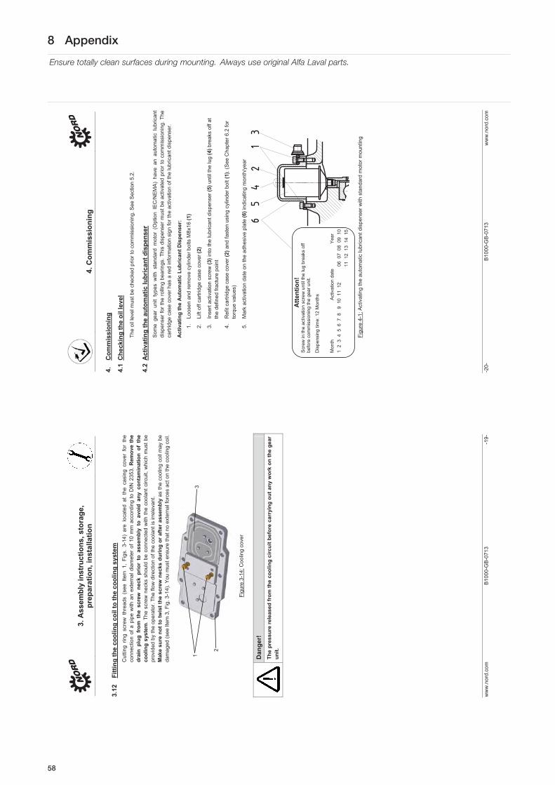
8 Appendix
Ensure totally clean surfaces during mounting. Always use original Alfa Laval parts.
3. A
ssem
bly
inst
ruct
ions
, sto
rage
, pr
epar
atio
n, in
stal
latio
n
ww
w.n
ord.
com
B
1000
-GB
-071
3 -1
9-
3.12
Fi
tting
the
cool
ing
coil
to th
e co
olin
g sy
stem
C
uttin
g rin
g sc
rew
thr
eads
(se
e Ite
m 1
, Fi
gs.
3-14
) ar
e lo
cate
d at
the
cas
ing
cove
r fo
r th
e co
nnec
tion
of a
pip
e w
ith a
n ex
tern
al d
iam
eter
of 1
0 m
m a
ccor
ding
to D
IN 2
353.
Rem
ove
the
drai
n pl
ug f
rom
the
scr
ew n
eck
prio
r to
ass
embl
y to
avo
id a
ny c
onta
min
atio
n of
the
co
olin
g sy
stem
.The
scr
ew n
ecks
sho
uld
be c
onne
cted
with
the
cool
ant c
ircui
t, w
hich
mus
t be
prov
ided
by
the
oper
ator
. The
flow
dire
ctio
n of
the
cool
ant i
s irr
elev
ant.
Mak
e su
re n
ot to
twis
t the
scr
ew n
ecks
dur
ing
or a
fter
asse
mbl
y as
the
cool
ing
coil
may
be
dam
aged
(see
Item
3, F
ig. 3
-14)
. You
mus
t ens
ure
that
no
exte
rnal
forc
es a
ct o
n th
e co
olin
g co
il.
Figu
re 3
-14:
Coo
ling
cove
r
Dan
ger!
Th
e pr
essu
re re
leas
ed fr
om th
e co
olin
g ci
rcui
t bef
ore
carr
ying
out
any
wor
k on
the
gear
un
it.
1
2
3
4. C
omm
issi
onin
g
-20-
B
1000
-GB
-071
3 w
ww
.nor
d.co
m
4.
Com
mis
sion
ing
4.1
Che
ckin
g th
e oi
l lev
el
The
oil l
evel
mus
t be
chec
ked
prio
r to
com
mis
sion
ing.
See
Sec
tion
5.2.
4.2
Act
ivat
ing
the
auto
mat
ic lu
bric
ant d
ispe
nser
S
ome
gear
uni
t ty
pes
with
sta
ndar
d m
otor
(O
ptio
n IE
C/N
EM
A)
have
an
auto
mat
ic l
ubric
ant
disp
ense
r for
the
rollin
g be
arin
gs. T
his
disp
ense
r mus
t be
activ
ated
prio
r to
com
mis
sion
ing.
The
ca
rtrid
ge c
ase
cove
r has
a re
d in
form
atio
n si
gn fo
r the
act
ivat
ion
of th
e lu
bric
ant d
ispe
nser
.
Act
ivat
ing
the
Aut
omat
ic L
ubric
ant D
ispe
nser
:
1.
Loos
en a
nd re
mov
e cy
linde
r bol
ts M
8x16
(1)
2.
Lift
off c
artri
dge
case
cov
er (2
)
3.
Inse
rt ac
tivat
ion
scre
w (3
) int
o th
e lu
bric
ant d
ispe
nser
(5) u
ntil
the
lug
(4) b
reak
s of
f at
the
defin
ed fr
actu
re p
oint
4.
Ref
it ca
rtrid
ge c
ase
cove
r (2)
and
fast
en u
sing
cyl
inde
r bol
t (1)
. (S
ee C
hapt
er 6
.2 fo
r to
rque
val
ues)
5.
Mar
k ac
tivat
ion
date
on
the
adhe
sive
pla
te (6
) ind
icat
ing
mon
th/y
ear
Figu
re 4
-1: A
ctiv
atin
g th
e au
tom
atic
lubr
ican
t dis
pens
er w
ith s
tand
ard
mot
or m
ount
ing
Atte
ntio
n!S
crew
in th
e ac
tivat
ion
scre
w u
ntil
the
lug
brea
ks o
ff be
fore
com
mis
sion
ing
the
gear
uni
t.
Dis
pens
ing
time:
12
Mon
ths
Mon
th
A
ctiv
atio
n da
te
Y
ear
1 2
3 4
5 6
7 8
9
10
11
12
0
6 0
7 0
8 0
9 1
0
11
12
13
14
15
58
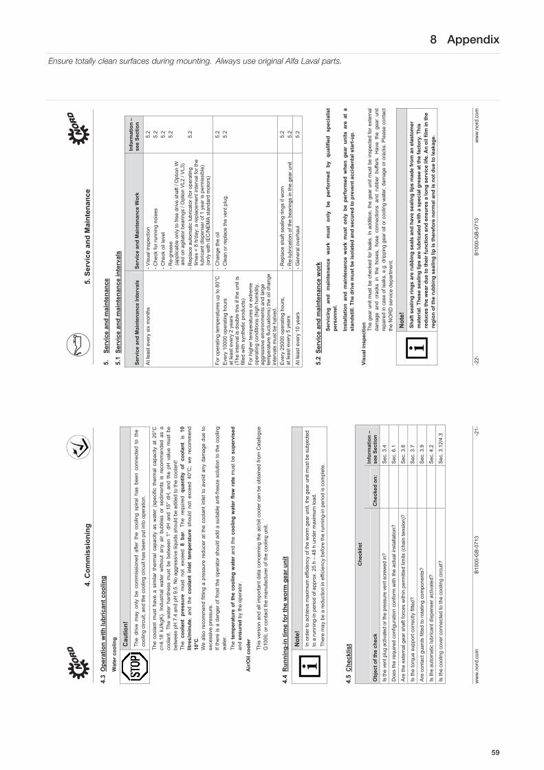
8 Appendix
Ensure totally clean surfaces during mounting. Always use original Alfa Laval parts.
4. C
omm
issi
onin
g
ww
w.n
ord.
com
B
1000
-GB
-071
3 -2
1-
4.3
Ope
ratio
n w
ith lu
bric
ant c
oolin
g
Wat
er c
oolin
g
Cau
tion!
The
driv
e m
ay o
nly
be c
omm
issi
oned
afte
r th
e co
olin
g sp
iral
has
been
con
nect
ed t
o th
e co
olin
g ci
rcui
t, an
d th
e co
olin
g ci
rcui
t has
bee
n pu
t int
o op
erat
ion.
The
cool
ant
mus
t ha
ve a
sim
ilar
ther
mal
cap
acity
as
wat
er (
spec
ific
ther
mal
cap
acity
at
20°C
c=
4.18
kJ/
kgK
). In
dust
rial
wat
er w
ithou
t an
y ai
r bu
bble
s or
sed
imen
ts i
s re
com
men
ded
as a
co
olan
t. Th
e w
ater
har
dnes
s m
ust
be b
etw
een
1° d
H a
nd 1
5° d
H,
and
the
pH v
alue
mus
t be
be
twee
n pH
7.4
and
pH
9.5
. No
aggr
essi
ve li
quid
s sh
ould
be
adde
d to
the
cool
ant!
Th
eco
olan
t pr
essu
re m
ust
not
exce
ed 8
bar
. Th
e re
quire
d qu
antit
y of
coo
lant
is
10
litre
s/m
inut
e, a
nd t
he c
oola
nt i
nlet
tem
pera
ture
sho
uld
not
exce
ed 4
0°C
; w
e re
com
men
d 10
°C.
We
also
rec
omm
end
fittin
g a
pres
sure
red
ucer
at t
he c
oola
nt in
let t
o av
oid
any
dam
age
due
to
exce
ssiv
e pr
essu
re.
If th
ere
is a
dan
ger o
f fro
st th
e op
erat
or s
houl
d ad
d a
suita
ble
anti-
freez
e so
lutio
n to
the
cool
ing
wat
er.
The
tem
pera
ture
of
the
cool
ing
wat
er a
nd th
e co
olin
g w
ater
flow
rat
e m
ust b
e su
perv
ised
and
ensu
red
by th
e op
erat
or.
Air/
Oil
cool
er
This
ver
sion
and
all
impo
rtant
dat
a co
ncer
ning
the
air/o
il co
oler
can
be
obta
ined
from
Cat
alog
ue
G10
00, o
r con
tact
the
man
ufac
ture
r of t
he c
oolin
g un
it.
4.4
Run
ning
-in ti
me
for t
he w
orm
gea
r uni
t
Not
e!In
ord
er to
ach
ieve
max
imum
effi
cien
cy o
f the
wor
m g
ear u
nit,
the
gear
uni
t mus
t be
subj
ecte
d
to a
runn
ing-
in p
erio
d of
app
rox.
25
h –
48 h
und
er m
axim
um lo
ad.
Ther
e m
ay b
e a
redu
ctio
n in
effi
cien
cy b
efor
e th
e ru
nnin
g-in
per
iod
is c
ompl
ete.
4.5
Che
cklis
t
Che
cklis
t
Obj
ect o
f the
che
ckC
heck
ed o
n:In
form
atio
n –
see
Sect
ion
Is th
e ve
nt p
lug
activ
ated
or t
he p
ress
ure
vent
scr
ewed
in?
Sec.
3.4
Doe
s th
e re
quire
d co
nfig
urat
ion
conf
orm
with
the
actu
al in
stal
latio
n?
S
ec. 6
.1
Are
the
exte
rnal
gea
r sha
ft fo
rces
with
in p
erm
itted
lim
its (c
hain
tens
ion)
?
Sec
. 3.6
Is th
e to
rque
sup
port
corre
ctly
fitte
d?
Sec
. 3.7
Are
con
tact
gua
rds
fitte
d to
rota
ting
com
pone
nts?
S
ec. 3
.9
Is th
e au
tom
atic
lubr
ican
t dis
pens
er a
ctiv
ated
? S
ec. 4
.2
Is th
e co
olin
g co
ver c
onne
cted
to th
e co
olin
g ci
rcui
t?
S
ec. 3
.12/
4.3
5. S
ervi
ce a
nd M
aint
enan
ce
-22-
B
1000
-GB
-071
3 w
ww
.nor
d.co
m
5.
Serv
ice
and
mai
nten
ance
5.1
Serv
ice
and
mai
nten
ance
inte
rval
s
Serv
ice
and
Mai
nten
ance
Inte
rval
sSe
rvic
e an
d M
aint
enan
ce W
ork
Info
rmat
ion
– se
e Se
ctio
n
At l
east
eve
ry s
ix m
onth
s - V
isua
l ins
pect
ion
- Che
ck fo
r run
ning
noi
ses
- Che
ck o
il le
vel
- Re-
grea
se
(app
licab
le o
nly
to fr
ee d
rive
shaf
t / O
ptio
n W
an
d on
agi
tato
r bea
rings
/ O
ptio
n V
L2 /
VL3
) - R
epla
ce a
utom
atic
lubr
icat
or (f
or o
pera
ting
times
< 8
h/d
ay: a
repl
acem
ent i
nter
val f
or th
e lu
bric
ant d
ispe
nser
of 1
yea
r is
perm
issi
ble)
(o
nly
with
IEC
/NE
MA
sta
ndar
d m
otor
s)
5.2
5.2
5.2
5.2
5.2
For o
pera
ting
tem
pera
ture
s up
to 8
0°C
E
very
100
00 o
pera
ting
hour
s at
leas
t eve
ry 2
yea
rs
(The
inte
rval
is d
oubl
e th
is if
the
unit
is
fille
d w
ith s
ynth
etic
pro
duct
s)
For h
ighe
r tem
pera
ture
s or
ext
rem
e op
erat
ing
cond
ition
s (h
igh
hum
idity
, ag
gres
sive
env
ironm
ents
and
larg
e te
mpe
ratu
re fl
uctu
atio
ns) t
he o
il ch
ange
in
terv
als
mus
t be
halv
ed.
- Cha
nge
the
oil
- Cle
an o
r rep
lace
the
vent
plu
g.
5.2
5.2
Eve
ry 2
5000
ope
ratin
g ho
urs,
at
leas
t eve
ry 5
yea
rs
- Rep
lace
sha
ft se
alin
g rin
gs if
wor
n - R
e-lu
bric
atio
n of
the
bear
ings
in th
e ge
ar u
nit
5.2
5.2
At l
east
eve
ry 1
0 ye
ars
- Gen
eral
ove
rhau
l 5.
2
5.2
Serv
ice
and
mai
nten
ance
wor
k Se
rvic
ing
and
mai
nten
ance
w
ork
mus
t on
ly
be
perf
orm
ed
by
qual
ified
sp
ecia
list
pers
onne
l.
Inst
alla
tion
and
mai
nten
ance
wor
k m
ust
only
be
perf
orm
ed w
hen
gear
uni
ts a
re a
t a
stan
dstil
l. Th
e dr
ive
mus
t be
isol
ated
and
sec
ured
to p
reve
nt a
ccid
enta
l sta
rt-u
p.
Visu
al in
spec
tion
The
gear
uni
t mus
t be
chec
ked
for l
eaks
. In
addi
tion,
the
gear
uni
t mus
t be
insp
ecte
d fo
r ext
erna
l da
mag
e an
d cr
acks
in
the
hose
s, h
ose
conn
ectio
ns a
nd r
ubbe
r bu
ffers
. H
ave
the
gear
uni
t re
paire
d in
cas
e of
leak
s, e
.g. d
rippi
ng g
ear o
il or
coo
ling
wat
er, d
amag
e or
cra
cks.
Ple
ase
cont
act
the
NO
RD
ser
vice
dep
artm
ent.
Not
e!Sh
aft s
ealin
g rin
gs a
re ru
bbin
g se
als
and
have
sea
ling
lips
mad
e fr
om a
n el
asto
mer
m
ater
ial.
Thes
e se
alin
g lip
s ar
e lu
bric
ated
with
a s
peci
al g
reas
e at
the
fact
ory.
Thi
s re
duce
s th
e w
ear d
ue to
thei
r fun
ctio
n an
d en
sure
s a
long
ser
vice
life
. An
oil f
ilm in
the
regi
on o
f the
rubb
ing
seal
ing
lip is
ther
efor
e no
rmal
and
is n
ot d
ue to
leak
age.
59

8 Appendix
Ensure totally clean surfaces during mounting. Always use original Alfa Laval parts.
5. S
ervi
ce a
nd M
aint
enan
ce
ww
w.n
ord.
com
B
1000
-GB
-071
3 -2
3-
Che
ck fo
r run
ning
noi
ses
If th
e ge
ar u
nit p
rodu
ces
unus
ual r
unni
ng n
oise
s an
d/or
vib
ratio
ns, t
his
coul
d in
dica
te d
amag
e to
th
e ge
ar u
nit I
n th
is c
ase
the
gear
sho
uld
be s
hut d
own
and
a ge
nera
l ove
rhau
l car
ried
out.
Che
ck th
e oi
l lev
el
Sec
tion
6.1
desc
ribes
the
ver
sion
s an
d th
e co
rres
pond
ing
oil
leve
l sc
rew
s. W
ith d
oubl
e ge
ar
units
, th
e oi
l lev
el m
ust
be c
heck
ed o
n bo
th u
nits
. Th
e pr
essu
re v
ent
mus
t be
at
the
posi
tion
mar
ked
in S
ectio
n 6.
1.
The
oil l
evel
doe
s no
t nee
d to
be
chec
ked
on g
ear u
nits
with
out o
il le
vel s
crew
(see
Sec
tion
6.1)
. G
ear u
nit t
ypes
that
are
not
sup
plie
d fu
ll of
oil
mus
t be
fille
d be
fore
the
oil l
evel
is c
heck
ed. (
see
“Cha
ngin
g th
e oi
l”)
Che
ckin
g th
e oi
l lev
el:
1.
The
oil l
evel
may
onl
y be
che
cked
whe
n th
e ge
ar u
nit
is a
t a
stan
dstil
l and
has
coo
led
dow
n. T
he g
ear u
nit m
ust b
e se
cure
d to
pre
vent
acc
iden
tal s
witc
h-on
. 2.
Th
e oi
l lev
el s
crew
cor
resp
ondi
ng to
the
vers
ion
mus
t be
scre
wed
out
. (S
ee S
ectio
n 6.
1)
Not
e!A
t the
firs
t oil
leve
l che
ck a
sm
all a
mou
nt o
f oil
may
esc
ape,
as
the
oil l
evel
may
be
belo
w th
e lo
wer
edg
e of
the
oil l
evel
hol
e.
3.
Gea
r uni
ts w
ith o
il le
vel s
crew
: The
max
imum
oil
leve
l is
the
low
er e
dge
of th
e oi
l lev
el h
ole.
Th
e m
inim
um o
il le
vel i
s 4
mm
bel
ow th
e oi
l lev
el h
ole.
If th
e oi
l lev
el is
too
low
, thi
s m
ust b
e co
rrec
ted
usin
g th
e co
rrec
t typ
e of
oil.
An
oil l
evel
gla
ss is
ava
ilabl
e in
stea
d of
the
oil l
evel
sc
rew
4.
G
ear u
nits
with
an
oil l
evel
ves
sel:
The
oil l
evel
mus
t be
chec
ked
in th
e oi
l lev
el v
esse
l with
the
aid
of t
he d
ipst
ick
plug
(th
read
G1
1/4)
. Th
e oi
l lev
el m
ust
be b
etw
een
the
uppe
r an
d lo
wer
mar
k w
hen
the
dips
tick
is c
ompl
etel
y sc
rew
ed in
(se
e Fi
g. 5
-2).
The
oil l
evel
mus
t be
corre
cted
with
the
corre
ct ty
pe o
f oil
if ne
cess
ary.
The
se g
earb
oxes
may
onl
y be
ope
rate
d in
th
e co
nfig
urat
ion
stat
ed in
Sec
tion
6.1.
5.
Th
e oi
l lev
el s
crew
or
the
cap
scre
w w
ith d
ipst
ick
and
all o
ther
loos
ened
scr
ews
mus
t be
co
rrect
ly re
-tigh
tene
d.
Figu
re 5
-2: C
heck
the
oil l
evel
with
a d
ipst
ick
5. S
ervi
ce a
nd M
aint
enan
ce
-24-
B
1000
-GB
-071
3 w
ww
.nor
d.co
m
Reg
reas
ing
Som
e ge
ar u
nit d
esig
ns (f
ree
driv
e sh
aft,
Opt
ion
W, a
gita
tor d
esig
ns V
L2 a
nd V
L3) a
re e
quip
ped
with
a re
grea
sing
dev
ice.
Fo
r agi
tato
r ver
sion
s V
L2 a
nd V
L3, t
he v
ent s
crew
loca
ted
oppo
site
to th
e gr
ease
nip
ple
mus
t be
unsc
rew
ed b
efor
e re
grea
sing
. Gre
ase
shou
ld b
e in
ject
ed u
ntil
a qu
antit
y of
20-
25g
esca
pes
from
th
e ve
nt h
ole.
Afte
r thi
s, th
e ve
nt p
lug
mus
t be
rein
serte
d an
d tig
hten
ed.
For
Opt
ion
W a
nd s
ome
IEC
ada
pter
s, th
e ou
ter
rolle
r be
arin
g m
ust b
e re
grea
sed
with
app
rox.
20
-25g
of g
reas
e vi
a th
e gr
ease
nip
ple
prov
ided
R
ecom
men
ded
grea
se: P
etam
o G
HY
133
N (s
ee S
ectio
n 6.
4: K
lübe
r Lub
ricat
ion)
.
Rep
laci
ng th
e au
tom
atic
lubr
ican
t dis
pens
er
Scr
ew-o
ff th
e ca
rtrid
ge c
ase
cove
r (2
), (s
ee F
ig. 4
-1).
The
lubr
icat
ion
disp
ense
r (5
) is
scr
ewed
ou
t and
repl
aced
with
a n
ew c
ompo
nent
(Par
t No.
283
010
0). T
hen
activ
ate
(see
Cha
pter
4.2
)!
Cha
ngin
g th
e oi
l Th
e fig
ures
in S
ectio
n 6.
1 sh
ow t
he o
il dr
ain
scre
w,
the
oil l
evel
scr
ew a
nd t
he p
ress
ure
vent
sc
rew
for v
ario
us d
esig
ns.
Seq
uenc
e:
1.
Pla
ce th
e dr
ip tr
ay b
elow
the
oil d
rain
scr
ew o
r the
oil
drai
n co
ck
2.
Com
plet
ely
rem
ove
oil l
evel
scr
ew, s
crew
ed s
ealin
g pl
ug w
ith d
ipst
ick
if an
oil
leve
l tan
k is
bei
ng u
sed
and
oil d
rain
scr
ew.
Dan
ger!
War
ning
: Hot
oil!
3.
Dra
in a
ll th
e oi
l fro
m th
e ge
ar u
nit.
4.
If th
e sc
rew
loc
k co
atin
g of
the
oil
drai
n sc
rew
or
oil
leve
l sc
rew
is
dam
aged
in
the
thre
ad,
a ne
w o
il le
vel
scre
w m
ust
be u
sed
or t
he t
hrea
d cl
eane
d an
d co
ated
with
se
curin
g lu
bric
ant,
e.g.
Loc
tite
242,
Lox
eal 5
4-03
prio
r to
inse
rting
. C
heck
the
sea
ling
ring
for d
amag
e. R
epla
ce w
ith a
new
sea
ling
ring
in c
ase
of d
amag
e.
5.
Sup
port
the
seal
rin
g, in
sert
the
oil d
rain
scr
ew in
to th
e ho
le a
nd ti
ghte
n to
the
corre
ct
torq
ue! (
See
Sec
tion
6.2
for t
orqu
e va
lues
) 6.
U
sing
a s
uita
ble
fillin
g de
vice
, ref
ill w
ith o
il of
the
sam
e ty
pe t
hrou
gh t
he o
il le
vel h
ole
until
oil
emer
ges
from
the
oil l
evel
hol
e. (
The
oil c
an a
lso
be fi
lled
thro
ugh
the
pres
sure
ve
nt s
crew
or
a se
alin
g pl
ug lo
cate
d hi
gher
tha
n th
e oi
l lev
el).
If an
oil
leve
l ves
sel i
s us
ed, f
ill th
e oi
l thr
ough
the
uppe
r inl
et (t
hrea
d G
1¼) u
ntil
the
oil l
evel
is s
et a
s de
scrib
ed
in S
ectio
n 5.
2.
7.
Wai
t at l
east
15
min
utes
, or a
t lea
st 3
0 m
inut
es if
an
oil l
evel
tank
is u
sed,
and
then
ch
eck
the
oil l
evel
. Pro
ceed
as
desc
ribed
in S
ectio
n 5.
2.
Not
e!Th
e oi
l doe
s no
t nee
d to
be
chan
ged
on g
ear u
nits
with
out o
il le
vel s
crew
(see
Sec
tion
6.1)
. Th
ese
gear
uni
ts a
re lu
bric
ated
for l
ife.
Sta
ndar
d he
lical
gea
r un
its h
ave
no o
il le
vel
scre
w.
Her
e, t
he o
il is
top
ped
up t
hrou
gh t
he
pres
sure
ven
t bol
t usi
ng th
e qu
antit
ies
liste
d in
the
tabl
e in
Sec
tion
6.5.
60

8 Appendix
Ensure totally clean surfaces during mounting. Always use original Alfa Laval parts.
5. S
ervi
ce a
nd M
aint
enan
ce
ww
w.n
ord.
com
B
1000
-GB
-071
3 -2
5-
Cle
anin
g or
repl
acin
g th
e ve
nt p
lug
Uns
crew
the
vent
scr
ew a
nd th
orou
ghly
cle
an it
(e.g
. with
com
pres
sed
air)
and
fit t
he v
ent s
crew
in
the
sam
e pl
ace,
If n
eces
sary
, use
a n
ew v
ent s
crew
with
a n
ew s
ealin
g rin
g.
Rep
laci
ng th
e sh
aft s
ealin
g rin
g S
haft
seal
ing
rings
are
rub
bing
sea
ls m
ade
from
an
elas
tom
er m
ater
ial a
nd a
ccor
ding
to
thei
r pr
inci
ple
are
subj
ect
to n
atur
al w
ear.
The
wea
ring
life
of s
haft
seal
ing
rings
dep
ends
on
man
y fa
ctor
s an
d ca
nnot
be
calc
ulat
ed in
adv
ance
. Onc
e th
e sh
aft s
ealin
g rin
g ha
s re
ache
d th
e en
d of
its
ser
vice
life
, the
oil
film
in th
e re
gion
of t
he s
ealin
g lip
incr
ease
s an
d a
mea
sura
ble
leak
age
with
drip
ping
oil
occu
rs. T
he s
haft
seal
ing
ring
mus
t the
n be
rep
lace
d. T
o re
duce
the
risk
of
leak
s du
e to
wor
n sh
aft s
ealin
g rin
gs w
e re
com
men
d th
at a
s a
prec
autio
n, th
e sh
aft s
ealin
g rin
gs
are
repl
aced
afte
r ev
ery
25,0
00 o
pera
ting
hour
s or
eve
ry 5
yea
rs.
The
spac
e be
twee
n th
e se
alin
g lip
and
the
pro
tect
ive
lip m
ust
be f
illed
app
roxi
mat
ely
50%
with
gre
ase
on f
ittin
g (re
com
men
ded
grea
se: P
ETA
MO
GH
Y 1
33N
). Ta
ke c
are
that
afte
r fitt
ing,
the
new
sha
ft se
alin
g rin
g do
es n
ot ru
n in
the
old
wea
r tra
ck.
Re-
lubr
icat
ing
bear
ings
For b
earin
gs w
hich
are
not
oil-
lubr
icat
ed a
nd w
hose
hol
es a
re c
ompl
etel
y ab
ove
the
oil l
evel
, re
plac
e th
e ro
ller b
earin
g gr
ease
(rec
omm
ende
d gr
ease
: PE
TAM
O G
HY
133
N).
Ple
ase
cont
act
the
NO
RD
ser
vice
dep
artm
ent.
Gen
eral
ove
rhau
l Th
e ge
ar u
nits
mus
t be
com
plet
ely
dism
antle
d Th
e fo
llow
ing
wor
k m
ust b
e ca
rrie
d ou
t:
C
lean
all
gear
uni
t com
pone
nts
E
xam
ine
all g
ear u
nit c
ompo
nent
s fo
r dam
age
A
ll da
mag
ed c
ompo
nent
s m
ust b
e re
plac
ed
A
ll ro
ller b
earin
gs m
ust b
e re
plac
ed
R
epla
ce b
ack
stop
s if
fitte
d
R
epla
ce a
ll se
als,
radi
al s
eals
and
Nilo
s rin
gs
R
epla
ce p
last
ic a
nd e
last
omer
com
pone
nts
of th
e m
otor
cou
plin
g
The
gene
ral o
verh
aul m
ust b
e ca
rrie
d ou
t by
qual
ified
per
sonn
el in
a s
peci
alis
t wor
ksho
p w
ith
appr
opria
te e
quip
men
t in
obse
rvan
ce o
f nat
iona
l reg
ulat
ions
and
law
s. W
e re
com
men
d th
at th
e ge
nera
l ove
rhau
l is
carr
ied
out b
y th
e N
OR
D s
ervi
ce d
epar
tmen
t.
6. A
ppen
dix
-26-
B
1000
-GB
-071
3 w
ww
.nor
d.co
m
6.
App
endi
x
6.1
Vers
ions
and
mai
nten
ance
Exp
lana
tion
of s
ymbo
ls fo
r the
follo
win
g ve
rsio
n ill
ustra
tions
:
Ven
t
Oil
leve
l
Oil
drai
n
Not
e!S
K 3
20, S
K 1
72, S
K 2
72, S
K 3
72K
, SK
273
and
SK
373
as w
ell a
s S
K 0
1282
NB
, SK
028
2 N
B,
SK
138
2 N
B a
nd U
NIV
ER
SA
L /
Min
iblo
c ge
ar u
nits
are
lubr
icat
ed f
or li
fe.
Thes
e ge
ar
units
do
not h
ave
an o
il fil
ler s
crew
.
UN
IVER
SAL
/ Min
iBlo
c w
orm
gea
r uni
ts
NO
RD
UN
IVE
RS
AL
/ M
iniB
loc
wor
m g
ear
units
are
sui
tabl
e fo
r al
l ins
talla
tion
posi
tions
. Th
ey
have
an
oil f
iller
whi
ch is
inde
pend
ent o
f the
the
vers
ion.
As
an o
ptio
n, ty
pes
SI a
nd S
MI c
an b
e eq
uipp
ed w
ith a
ven
t scr
ew. G
ear
units
with
ven
ts m
ust
be in
stal
led
in th
e st
ated
pos
ition
(see
sec
tion
6.5)
Type
s S
I, S
MI,
S, S
M a
nd S
U a
s 2-
stag
e ge
ar u
nit t
ypes
and
type
s S
I, S
MI a
s w
orm
gea
r uni
ts
for d
irect
mot
or m
ount
ing
have
an
oil f
iller
whi
ch d
epen
ds o
n th
e ve
rsio
n an
d m
ust b
e in
stal
led
in
the
stat
ed p
ositi
on.
61

8 Appendix
Ensure totally clean surfaces during mounting. Always use original Alfa Laval parts.
6. A
ppen
dix
ww
w.n
ord.
com
B
1000
-GB
-071
3 -2
7-
Para
llel s
haft
gear
uni
ts w
ith o
il le
vel v
esse
l
The
follo
win
g ap
plie
s fo
r SK
928
2, S
K 9
382,
SK
102
82, S
K 1
0382
, SK
112
82, S
K 11
382
para
llel
gear
uni
ts a
nd S
K 1
2382
in th
e M
4 co
nfig
urat
ion
with
oil
leve
l ves
sels
:
Figu
re 6
-1: O
il le
vel c
heck
with
oil
leve
l tan
k
-28-
B
1000
-071
3 w
ww
.nor
d.co
m
SK 0
3 SK
13
SK 2
3 SK
33N
SK
43
SK 5
3
SK 0
2
SK 1
2 SK
22
SK 3
2 SK
42
SK 5
2 SK
62N
SK 1
1E
SK 2
1E
SK 3
1E
SK 4
1E
SK 5
1E
SK 6
2 SK
72
SK 8
2 SK
92
SK 1
02
SK 6
3*
SK 7
3*
SK 8
3*
SK 9
3*
SK 1
03*
M1
B3+
B5
M2
V6+V
3
M5
B6+
B5I
I
M3
B8+
B5I
M4
V5+V
1M6
B7+
B5I
II
M1
B3+
B5
M2
V6+V
3
M5
B6+
B5I
I
M3
B8+
B5I
M4
V5+V
1M6
B7+
B5I
II
M1
B3+
B5
M2
V6+V
3
M5
B6+
B5I
I
M3
B8+
B5I
M4
V5+V
1
M6
B7+
B5I
II
M6
B7+
B5I
II
M1
B3+
B5
M2
V6+V
3 M5
B6+
B5I
I
M3
B8+
B5I
M4
V5+V
1
*
*
62

8 Appendix
Ensure totally clean surfaces during mounting. Always use original Alfa Laval parts.
ww
w.n
ord.
com
B
1000
-071
3 -2
9-
M4
V1+V
5
M6
B7+
B5I
II
SK
472
S
K 5
72
SK
672
S
K 7
72
SK
872
S
K 9
72
SK
473
S
K 5
73
SK
673
S
K 7
73
SK
873
* S
K 9
73*
SK
372
.1
SK
572
.1
SK
672
.1
SK
373
.1
SK
573
.1
SK
673
.1
SK 3
72.1
F SK
572
.1F
SK 6
72.1
F SK
373
.1F
SK 5
73.1
F SK
673
.1F
M1
M2 M5
M3
M4
M6
M1
M2
M5
M3
M6
M4
SK 7
72.1
SK
872
.1
SK 9
72.1
SK
773
.1*
SK 8
73.1
* SK
973
.1*
M1
M2
M5
M3
M6
M4
*
*
*
*
*
M3
B8+
B5I
M5
B6+
B5I
I
M2
V3+V
6
M1
B3+
B5
-30-
B
1000
-071
3 w
ww
.nor
d.co
m
SK 0
72.1
SK
172
.1
M1
M2
M5
M3
M4
M6
M1
M2 M
5
M3
M4M6
SK 0
72.1
F
SK 1
72.1
F
M4
43M1
M2 M5
M3
M4
M6
SK 7
72.1
FSK
872
.1F
SK 9
72.1
F SK
773
.1F*
SK 8
73.1
F*SK
973
.1F*
*
*
*
*
63

8 Appendix
Ensure totally clean surfaces during mounting. Always use original Alfa Laval parts.
ww
w.n
ord.
com
B
1000
-071
3 -3
1-
44
M1
B3+
B5
M2
V6+V
3
M3
B8+
B5I
M1
B3+
B5
M2
V6+V
3
M3
B8+
B5I
SK 0
SK 0
1 SK
20
SK 2
5 SK
30
SK 3
3
SK 0
10
SK 2
00
SK 2
50
SK 3
00
SK 3
30
M4
V1+V
5
M6
B7+
B5I
II
M5
B6+
B5I
I
M4
V1+V
5
M6
B7+
B5I
II
M5
B6+
B5I
I
-32-
B
1000
-071
3 w
ww
.nor
d.co
m
SK 1
282
SK 2
282
SK 3
282
SK 4
282
SK 5
282
SK 0
182N
BSK
028
2NB
SK 1
382N
B*
* 2
7
SK 2
382
SK 3
382
SK 4
382
SK 5
382
M1
H1
M5
H4
M2
H6
M6
H3
M3
H2
M4
H5
M1
H1
M5
H4
M2
H6
M6
H3
M3
H2
M4
H5 M1
H1
SK 6
282*
SK
728
2*
SK 8
282*
SK
928
2*
SK 1
0282
*SK
112
82*
SK 6
382
SK 7
382
SK 8
382
SK 9
382
SK 1
0382
SK
113
82
SK12
382
M5
H4M
2H
6M
6H
3
M3
H2
M4
H5
*
64

8 Appendix
Ensure totally clean surfaces during mounting. Always use original Alfa Laval parts.
ww
w.n
ord.
com
B
1000
-071
3 -3
3-
SK
901
2.1
SK
901
6.1
SK
902
2.1
SK
903
2.1
SK
904
2.1
SK
905
2.1
SK
906
2.1
SK
907
2.1
SK
908
2.1
SK
908
6.1
SK
909
2.1
SK
909
6.1
SK 9
013.
1 S
K 9
017.
1 S
K 9
023.
1 S
K 9
033.
1 S
K 9
043.
1 S
K 9
053.
1
SK
921
72
SK
923
72
SK
926
72
SK
927
72
M1
B3
M2
B6
M5
V5
M3
B8
M4
B3IM
6V6
M1
B3
M2
B6
M3
B8
M4
B3I
M6
V6
M5
V5
M1
B3
M2
B6
M3
B8
M4
B3IM6
V6
M5
V5
SK 9
2072
M1
B3
M2
B6
M5
V5
M3
B8
M4
B3I
M6
V6
-34-
B
1000
-071
3 w
ww
.nor
d.co
m
SK 9
2172
S
K 9
2372
S
K 9
2672
S
K 9
2772
M1
H1+
B5I
M2
H4+
B5
M5
H5+
V1
M3
H2+
B5I
II
M4
H3+
B5I
I
M6
H6+
V3
SK 9
2072
M1
H1+
B5I M
2H
4+B
5
M5
H5+
V1
M3
H2+
B5I
II
M4
H3+
B5I
IM6
H6+
V3
SK
920
72.1
S
K 9
2172
.1
SK
923
72.1
S
K 9
2672
.1
SK
927
72.1
SK
930
72.1
S
K 9
3172
.1
SK
933
72.1
S
K 9
3672
.1
SK
937
72.1
M1
M2
M5
M3
M4
M6
M1
M2
M5
M3
M4
M6
65

8 Appendix
Ensure totally clean surfaces during mounting. Always use original Alfa Laval parts.
ww
w.n
ord.
com
B
1000
-071
3 -3
5-
SK 9
012.
1 S
K 9
016.
1 S
K 9
022.
1 S
K 9
032.
1 S
K 9
042.
1 S
K 9
052.
1 S
K 9
062.
1 S
K 9
072.
1 S
K 9
082.
1 S
K 9
086.
1 S
K 9
092.
1 S
K 9
096.
1
SK 9
013.
1 S
K 9
017.
1 S
K 9
023.
1 S
K 9
033.
1 S
K 9
043.
1 S
K 9
053.
1
M1
H1+
B5I
M2
H4+
B5
M5
H5+
V1
M3
H2+
B5I
II
M4
H3+
B5I
I
M6
H6+
V3
M1
H1+
B5I
M2
H4+
B5
M5
H5+
V1
M3
H2+
B5I
II
M4
H3+
B5I
IM6
H6+
V3
SK
020
50 S
K 1
2063
SK
120
80 S
K 3
2100
SK
421
25
SK
130
50
SK
130
63
SK
130
80
SK
331
00
SK
431
25
M1
B3
M2
B6
M3
B8
M4
B3IM6
V6
M5
V5
M1
B3
M2
B6
M3
B8
M4
B3IM6
V6
M5
V5
-36-
B
1000
-071
3 w
ww
.nor
d.co
m
SK
020
50
SK
120
63
SK
120
80
SK
321
00
SK
421
25
SK 1
3050
S
K 1
3063
S
K 1
3080
S
K 3
3100
S
K 4
3125
M1
H1+
B5I
M2
H4+
B5
M5
H5+
V1
M3
H2+
B5I
II
M4
H3+
B5I
I
M6
H6+
V3
M1
H1+
B5I
M2
H4+
B5
M5
H5+
V1
M3
H2+
B5I
II
M4
H3+
B5I
I
M6
H6+
V3
SK
020
40 S
K 0
2040
M1
B3
M2
B6
M5
V5
M3
B8
M4
B3IM6
V6
M1
H1+
B5I
M2
H4+
B5
M5
H5+
V1
M3
H2+
B5I
II
M4
H3+
B5I
I
M6
H6+
V3
66

8 Appendix
Ensure totally clean surfaces during mounting. Always use original Alfa Laval parts.
ww
w.n
ord.
com
B
1000
-071
3 -3
7-
SK 1
S32
– SK
1S6
3 SK
1SU
32 –
SK
1SU
63
SK 1
SM31
– S
K 1
SM63
SK
1SI
31 –
SK
1SI
75
SK
1SI
S31
– SK
1SI
S75
SK 1
SMI3
1 –
SK 1
SMI7
5 SK
1SI
D31
– S
K 1
SID
75
SK 1
SIS-
D31
– S
K 1
SIS-
D63
SK
1SM
ID31
– S
K 1
SMID
75
SK 2
S32N
B –
SK
2S6
3NB
SK
2SU
32N
B- S
K 2
SU63
NB
SK
2SM
40 –
SK
2SM
63
SK 2
SIS-
D40
– S
K 2
SIS-
D63
SK
2SI
D40
– S
K 2
SID
63
SK 2
SMID
40 –
SK
2SM
ID63
26
M3
M4
M6
M2
M5
M1
6. A
ppen
dix
-38-
B
1000
-GB
-071
3 w
ww
.nor
d.co
m
6.2
Torq
ue v
alue
s
Bol
t Tor
ques
[Nm
]
Size
Scr
ew c
onne
ctio
ns in
the
stre
ngth
cla
sses
Sea
ling
scre
ws
Thre
aded
pi
n on
co
uplin
g
Scr
ew
conn
ectio
ns o
n pr
otec
tive
cove
rs
8.8
10.9
12
.9
M4
3.2
5 6
- -
M5
6.4
9 11
-
2
M6
11
16
19
- -
6.4
M8
27
39
46
11
10
11
M10
53
78
91
11
17
27
M12
92
13
5 15
5 27
40
53
M16
23
0 33
5 39
0 -
- 92
M20
46
0 66
0 77
0 -
- 23
0
M24
79
0 11
50
1300
80
-
460
M30
16
00
2250
26
50
170
-
M36
27
80
3910
47
10
- -
M42
44
70
6290
75
40
- -
G1¼
--
-20
-
6.3
Trou
bles
hoot
ing
Gea
r uni
t mal
func
tions
Faul
tP
ossi
ble
caus
e R
emed
y
Unu
sual
runn
ing
nois
es,
vibr
atio
ns
Oil
too
low
or
bear
ing
dam
age
or
toot
hed
whe
el d
amag
e C
onsu
lt N
OR
D S
ervi
ce
Oil
esca
ping
from
gea
r uni
t or
mot
orD
efec
tive
seal
C
onsu
lt N
OR
D S
ervi
ce
Oil
esca
ping
from
pr
essu
re v
ent
Inco
rrect
oil
leve
l or i
ncor
rect
, co
ntam
inat
ed o
il or
unf
avou
rabl
e op
erat
ing
cond
ition
s
Oil
chan
ge
Use
oil
expa
nsio
n ta
nk (O
ptio
n O
A)
Gea
r uni
t bec
omes
too
hot
Unf
avou
rabl
e in
stal
latio
n co
nditi
ons
or g
ear u
nit d
amag
e
Con
sult
NO
RD
Ser
vice
Sho
ck w
hen
switc
hed
on,
vibr
atio
ns
Def
ectiv
e m
otor
cou
plin
g or
lo
ose
gear
uni
t mou
ntin
g or
de
fect
ive
rubb
er e
lem
ent
Rep
lace
ela
stom
er g
ear r
im,
tight
en m
otor
and
gea
r uni
t fa
sten
ing
bolts
, rep
lace
rubb
er
elem
ent
Driv
e sh
aft d
oes
not r
otat
e al
thou
gh m
otor
is ru
nnin
g
Frac
ture
in g
ear u
nit o
r de
fect
ive
mot
or c
oupl
ing
or
shrin
k di
sc s
lippa
ge
Con
sult
NO
RD
Ser
vice
Atte
ntio
n!
War
ning
: shu
t dow
n th
e ge
ar u
nit i
mm
edia
tely
sho
uld
any
of th
e ab
ove
faul
ts o
ccur
!
67

8 Appendix
Ensure totally clean surfaces during mounting. Always use original Alfa Laval parts.
6. A
ppen
dix
ww
w.n
ord.
com
B
1000
-GB
-071
3 -3
9-
6.4
Lubr
ican
ts
With
the
exce
ptio
n of
type
SK
112
82, S
K 1
1382
, SK
123
82 a
nd S
K 9
096.
1 ge
ar u
nits
, all
gear
un
its a
re fi
lled
with
lubr
ican
t rea
dy fo
r ope
ratio
n in
the
requ
ired
inst
alla
tion
posi
tion
whe
n de
liver
ed. T
his
initi
al fi
lling
cor
resp
onds
to a
lubr
ican
t fro
m th
e co
lum
n fo
r the
am
bien
t te
mpe
ratu
res
(nor
mal
ver
sion
) in
the
lubr
ican
t tab
le.
Rol
ler b
earin
g gr
ease
s Th
is ta
ble
show
s co
mpa
rabl
e ro
ller b
earin
g gr
ease
s fro
m v
ario
us m
anuf
actu
rers
. The
m
anuf
actu
rer c
an b
e ch
ange
d fo
r a g
iven
gre
ase
type
. Get
riebe
bau
NO
RD
mus
t be
cont
acte
d in
ca
se o
f cha
nge
of g
reas
e ty
pe o
r am
bien
t tem
pera
ture
rang
e, a
s ot
herw
ise
no w
arra
nty
for t
he
func
tiona
lity
of o
ur g
ear u
nits
can
be
acce
pted
.
Lubr
ican
t typ
eA
mbi
ent
tem
pera
ture
Min
eral
oil-
base
d gr
ease
-3
0 …
60°
C
Ene
rgre
ase
LS 2
Lo
ngtim
e PD
2
REN
OLI
T
GP
2 -
Mob
ilux
EP
2
Gad
us S
2
V100
2
Ene
rgre
ase
LS-E
P 2
REN
OLI
T LZ
R 2
H
-50
… 4
0°C
-
Opt
item
p LG
2
RE
NO
LIT
JP
161
9 -
- -
Synt
hetic
gre
ase
-25
… 8
0°C
E
nerg
reas
e S
Y 2
202
Trib
ol 4
747
RE
NO
LIT
H
LT 2
P
ETA
MO
GH
Y 13
3 N
M
obilt
emp
SHC
32
Cas
sida
E
PS
2
REN
OLI
T
LST
2 K
lübe
rple
x
BEM
41-
132
Bio
degr
adab
le
grea
se-2
5 …
40°
C
Bio
grea
se
EP 2
-
PLA
NTO
GE
L 2
SK
lübe
rbio
M
72-
82
Mob
il SH
C
Gre
ase
102
EA
L
Nat
urel
le
Gre
ase
EP2
Food
stuf
f-co
mpa
tible
gr
ease
-25
… 4
0°C
-
Obe
en U
F 2
REN
OLI
T
G 7
FG
1
Klü
bers
ynth
U
H1
14-1
51
Mob
ilgre
ase
FM 2
22
Cas
sida
RLS
2
6. A
ppen
dix
-40-
B
1000
-GB
-071
3 w
ww
.nor
d.co
m
Lubr
ican
t tab
le
This
tabl
e sh
ows
com
para
ble
lubr
ican
ts fr
om v
ario
us m
anuf
actu
rers
. The
man
ufac
ture
r can
be
chan
ged
with
in a
par
ticul
ar v
isco
sity
or l
ubric
ant t
ype.
Get
riebe
bau
NO
RD
mus
t be
cont
acte
d in
ca
se o
f cha
nge
of v
isco
sity
or l
ubric
ant t
ype,
as
othe
rwis
e no
war
rant
y fo
r the
func
tiona
lity
of o
ur
gear
boxe
s ca
n be
acc
epte
d.
Lubr
ican
t typ
eD
etai
ls o
n ty
pe p
late
D
IN (I
SO) /
A
mbi
ent
tem
pera
ture
Min
eral
oil
CLP
680
IS
O V
G 6
80
0...4
0°C
Ene
rgol
GR
-XP
680
Al
pha
EP 6
80
Alph
a SP
680
O
ptig
ear B
M
680
Trib
ol 1
100/
680
REN
OLI
N C
LP
680
REN
OLI
N C
LP
680
Plu
s
Klü
bero
il
GE
M 1
-680
N
Mob
ilgea
r60
0 X
P 6
80
Om
ala
S2
G 6
80
CLP
220
IS
O V
G 2
20
-10…
40°C
Ene
rgol
GR
-XP
220
Al
pha
EP 2
20
Alph
a SP
220
O
ptig
ear B
M
220
Trib
ol 1
100/
220
REN
OLI
N C
LP
220
REN
OLI
N C
LP
220
Plu
s
Klü
bero
il
GE
M 1
-220
N
Mob
ilgea
r60
0 X
P 2
20
Om
ala
S2
G 2
20
CLP
100
IS
O V
G 1
00
-15…
25°C
Ene
rgol
GR
-XP
100
Al
pha
EP 1
00
Alph
a SP
100
O
ptig
ear B
M
100
Trib
ol 1
100/
100
REN
OLI
N C
LP
100
REN
OLI
N C
LP
100
Plu
s
Klü
bero
il
GE
M 1
-100
N
Mob
ilgea
r60
0 X
P 1
00
Om
ala
S2
G 1
00
Synt
hetic
oil
(Pol
ygly
col)
CLP
PG
680
IS
O V
G 6
80
-20.
..40°
C
- A
lpha
syn
GS
680
Trib
ol 8
00/6
80
REN
OLI
N P
G
680
Klü
bers
ynth
G
H 6
-680
M
obil
Gly
goyl
e 68
0 O
mal
a S
4 W
E 68
0
CLP
PG
220
IS
O V
G 2
20
-25…
80°C
Ene
rsyn
S
G-X
P 2
20
Alp
hasy
n G
S 22
0A
lpha
syn
PG
22
0Tr
ibol
800
/220
REN
OLI
N P
G
220
Klü
bers
ynth
G
H 6
-220
M
obil
Gly
goyl
e 22
0 O
mal
a S
4 W
E 22
0
Synt
hetic
oil
(h
ydro
carb
on)
CLP
HC
460
IS
O V
G 4
60
-30…
80°C
- A
lpha
syn
EP
460
Trib
ol 1
510/
460
Opt
igea
r S
ynth
etic
X 4
60
REN
OLI
N
Uni
syn
CLP
460
Klü
bers
ynth
G
EM
4-4
60 N
M
obil
SHC
634
O
mal
a S
4 G
X 4
60
CLP
HC
220
IS
O V
G 2
20
-40…
80°C
- A
lpha
syn
EP
22
0Tr
ibol
151
0/22
0O
ptig
ear
Syn
thet
ic X
220
REN
OLI
N
Uni
syn
CLP
220
Klü
bers
ynth
G
EM
4-2
20 N
M
obil
SHC
630
O
mal
a S
4 G
X 2
20
Bio
-deg
rada
ble
oil
CLP
E 6
80
ISO
VG
680
-5
…40
°C
- -
PLA
NTO
GE
AR
68
0 S
- -
-
CLP
E 2
20
ISO
VG
220
-5
…40
°C
- Tr
ibol
Bio
Top
1418
/220
P
LAN
TOG
EA
R22
0 S
Klü
bers
ynth
G
EM 2
-220
-
Nat
urel
le
Gea
rFl
uid
EP
22
0Fo
od g
rade
oil
CLP
PG
H1
680
ISO
VG
680
-5
…40
°C
- Tr
ibol
Fo
odP
roof
1800
/680
- K
lübe
rsyn
th
UH
1 6-
680
Mob
ilG
lygo
yle
680
C
assi
da
Flui
d W
G
680
CLP
PG
H1
220
ISO
VG
220
-2
5…40
°C
- Tr
ibol
Fo
odP
roof
1800
/220
- K
lübe
rsyn
th
UH
1 6-
220
Mob
ilG
lygo
yle
220
Cas
sida
Fl
uid
WG
22
0
CLP
HC
H1
680
ISO
VG
680
-5
…40
°C
- O
ptile
b G
T 68
0 G
ER
ALY
N S
F 68
0K
lübe
roil
4
UH
1-68
0 N
-
Cas
sida
Fl
uid
GL
680
CLP
HC
H1
220
ISO
VG
220
-2
5…40
°C
- O
ptile
b G
T 22
0 G
ER
ALY
N S
F 22
0K
lübe
roil
4
UH
1-22
0 N
M
obil
SHC
Cib
us
220
Cas
sida
Fl
uid
GL
220
Gea
r uni
t liq
uid
grea
se
-2
5 …
60°
C
Ene
rgre
ase
LS-E
P 0
0 Lo
ngtim
e P
D 0
0Tr
ibol
3020
/100
0-00
REN
OLI
T D
UR
APLE
XE
P 0
0
MIC
RO
LUBE
G
B 0
0 M
obil
Cha
ssis
G
reas
e LB
Z
Alv
ania
E
P(L
F)2
RE
NO
LIT
LST
00K
lübe
rsyn
th
GE
46-
1200
M
obil
Gly
goyl
e G
reas
e 00
-
68

8 Appendix
Ensure totally clean surfaces during mounting. Always use original Alfa Laval parts.
6. A
ppen
dix
ww
w.n
ord.
com
B
1000
-GB
-071
3 -4
1-
6.5
Lubr
ican
t qua
ntiti
es
Not
e!A
fter
chan
ging
the
lubr
ican
t, an
d in
par
ticul
ar a
fter
the
initi
al fi
lling,
the
oil l
evel
may
cha
nge
durin
g th
e fir
st fe
w h
ours
of o
pera
tion,
as
the
oil g
alle
ries
and
hollo
w s
pace
s on
ly fi
ll gr
adua
lly
durin
g op
erat
ion.
The
oil
leve
l is
still
with
in th
e pe
rmis
sibl
e to
lera
nce.
If
at th
e ex
pres
s re
ques
t of t
he c
usto
mer
, an
oil i
nspe
ctio
n gl
ass
is in
stal
led
at a
n ad
ditio
nal
char
ge,
we
reco
mm
end
that
the
cus
tom
er c
orre
cts
the
oil l
evel
afte
r an
ope
ratin
g pe
riod
of
appr
ox. 2
hou
rs, s
o th
at w
hen
the
gear
uni
t is
at a
sta
ndst
ill a
nd h
as c
oole
d do
wn,
the
oil l
evel
is
vis
ible
in th
e in
spec
tion
glas
s. O
nly
then
, is
it po
ssib
le to
che
ck th
e oi
l lev
el b
y m
eans
of t
he
insp
ectio
n gl
ass.
The
fillin
g qu
antit
ies
stat
ed in
the
follo
win
g ta
bles
are
for g
uida
nce
only
. The
pre
cise
qua
ntiti
es
vary
dep
endi
ng o
n th
e ex
act g
ear
ratio
. Whe
n fil
ling,
alw
ays
obse
rve
the
oil l
evel
scr
ew h
ole
as a
n in
dica
tor o
f the
pre
cise
qua
ntity
of o
il.
* Typ
e S
K11
282,
SK
1138
2, S
K12
382
and
SK
909
6.1
gear
uni
ts a
re n
orm
ally
sup
plie
d w
ithou
t oil.
-42-
B
1000
-071
3 w
ww
.nor
d.co
m
[L] 6
.1M
1M
2M
3M
4M
5M
6M
1M
2M
3M
4M
5M
6 6
.1B
3V
6B
8V
5B
6B
7B
5V
3B
5IV
1B
5II
B5I
IIS
K11
E0,
250,
500,
550,
400,
350,
350,
300,
350,
500,
300,
400,
40
SK
21E
0,60
1,20
1,20
1,00
1,00
1,00
0,50
1,40
1,10
0,70
0,90
0,90
SK
31E
1,10
2,70
2,20
2,30
1,70
1,70
0,80
1,30
1,65
1,10
2,00
2,00
SK
41E
1,70
2,60
3,30
2,50
2,60
2,60
1,00
2,60
2,80
1,60
3,30
3,30
SK
51E
2,20
4,40
4,70
4,00
3,40
3,40
1,80
3,50
4,10
3,00
3,80
3,80
[L]
SK
020,
150,
600,
700,
600,
400,
400,
250,
600,
600,
600,
500,
50
SK
120,
250,
750,
850,
750,
500,
500,
350,
850,
900,
900,
600,
60
SK
220,
501,
801,
801,
801,
351,
350,
702,
002,
001,
801,
551,
55
SK
320,
902,
502,
502,
902,
002,
001,
302,
903,
303,
102,
402,
40
SK
421,
304,
504,
504,
303,
203,
201,
804,
404,
504,
003,
703,
70
SK
522,
507,
006,
806,
805,
105,
103,
006,
806,
207,
405,
605,
60
[L]
SK
626,
5015
,00
13,0
016
,00
15,0
015
,00
7,00
15,0
014
,00
18,5
016
,00
16,0
0
SK
7210
,00
23,0
018
,00
26,0
023
,00
23,0
010
,00
23,0
018
,50
28,0
023
,00
23,0
0
SK
8214
,00
35,0
027
,00
44,0
032
,00
32,0
015
,00
37,0
029
,00
45,0
034
,50
34,5
0
SK
9225
,00
73,0
047
,00
76,0
052
,00
52,0
026
,00
73,0
047
,00
78,0
052
,00
52,0
0
SK
102
36,0
079
,00
66,0
010
2,00
71,0
071
,00
40,0
081
,00
66,0
010
4,00
72,0
072
,00
[L]
SK
030,
301,
000,
800,
900,
600,
600,
500,
800,
901,
100,
800,
80
SK
130,
601,
251,
101,
200,
700,
700,
851,
201,
201,
200,
950,
95
SK
231,
302,
402,
302,
351,
601,
601,
502,
602,
502,
802,
802,
80
SK
33N
1,60
2,90
3,20
3,70
2,30
2,30
2,50
3,40
3,50
4,40
2,60
2,60
SK
433,
005,
605,
206,
603,
603,
603,
505,
705,
006,
104,
104,
10
SK
534,
508,
707,
708,
706,
006,
005,
208,
407,
008,
906,
706,
70
[L]
SK
6313
,00
14,5
014
,50
16,0
013
,00
13,0
013
,50
14,0
015
,50
18,0
014
,00
14,0
0
SK
7320
,50
20,0
022
,50
27,0
020
,00
20,0
022
,00
22,5
023
,00
27,5
020
,00
20,0
0
SK
8330
,00
31,0
034
,00
37,0
033
,00
33,0
031
,00
34,0
035
,00
40,0
034
,00
34,0
0
SK
9353
,00
70,0
059
,00
72,0
049
,00
49,0
053
,00
70,0
059
,00
74,0
049
,00
49,0
0
SK
103
74,0
071
,00
74,0
097
,00
67,0
067
,00
69,0
078
,00
78,0
099
,00
67,0
067
,00
69

8 Appendix
Ensure totally clean surfaces during mounting. Always use original Alfa Laval parts.
ww
w.n
ord.
com
B
1000
-071
3 -4
3-
[L]
[L]
6.1
M1
M2
M3
M4
M5
M6
6.1
M1
M2
M3
M4
M5
M6
SK
072.
10,
160,
320,
210,
230,
180,
20S
K07
2.1
F0,
160,
320,
210,
230,
180,
20
SK
172.
10,
270,
590,
420,
450,
320,
39S
K17
2.1
F0,
270,
590,
420,
450,
320,
39
SK
372.
10,
451,
050,
751,
000,
600,
65S
K37
2.1
F0,
451,
050,
751,
000,
600,
65
SK
572.
10,
751,
901,
502,
001,
101,
15S
K57
2.1
F0,
751,
901,
502,
001,
101,
15
SK
672.
11,
102,
602,
152,
701,
551,
65S
K67
2.1
F1,
102,
602,
152,
701,
551,
65
SK
772.
11,
353,
652,
253,
151,
352,
15S
K77
2.1
F1,
353,
652,
253,
151,
352,
15
SK
872.
13,
208,
005,
307,
002,
804,
60S
K87
2.1
F3,
208,
005,
307,
002,
804,
60
SK
972.
14,
5012
,90
8,10
12,7
04,
607,
80S
K97
2.1
F4,
5012
,90
8,10
12,7
04,
607,
80
SK
772.
1VL
2,00
3,65
2,25
3,15
1,35
2,15
SK
772.
1VL
F2,
003,
652,
253,
151,
352,
15
SK
872.
1VL
5,00
8,00
5,30
7,00
2,80
4,60
SK
872.
1VL
F5,
008,
005,
307,
002,
804,
60
SK
972.
1VL
8,50
12,9
08,
1012
,70
4,60
7,80
SK
972.
1VL
F8,
5012
,90
8,10
12,7
04,
607,
80
[L]
[L]
6.1
M1
M2
M3
M4
M5
M6
6.1
M1
M2
M3
M4
M5
M6
SK
373.
10,
451,
050,
751,
000,
600,
65S
K37
3.1
F0,
451,
050,
751,
000,
600,
65
SK
573.
10,
751,
901,
502,
001,
101,
15S
K57
3.1
F0,
751,
901,
502,
001,
101,
15
SK
673.
11,
102,
602,
152,
701,
551,
65S
K67
3.1
F1,
102,
602,
152,
701,
551,
65
SK
773.
11,
953,
503,
202,
902,
252,
95S
K77
3.1
F1,
953,
503,
202,
902,
252,
95
SK
873.
14,
057,
606,
856,
555,
006,
55S
K87
3.1
F4,
057,
606,
856,
555,
006,
55
SK
973.
17,
4012
,20
11,1
011
,60
8,00
10,9
0S
K97
3.1
F7,
4012
,20
11,1
011
,60
8,00
10,9
0
SK
773.
1VL
1,95
3,50
3,20
2,90
2,25
2,95
SK
773.
1VL
F1,
953,
503,
202,
902,
252,
95
SK
873.
1VL
4,05
7,60
6,85
6,55
5,00
6,55
SK
873.
1VL
F4,
057,
606,
856,
555,
006,
55
SK
973.
1VL
7,40
12,2
011
,10
11,6
08,
0010
,90
SK
973.
1VL
F7,
4012
,20
11,1
011
,60
8,00
10,9
0
-44-
B
1000
-071
3 w
ww
.nor
d.co
m
[L] 6
.1M
1M
2M
3M
4M
5M
6M
1M
2M
3M
4M
5M
6 6
.1B
3V
6B
8V
5B
6B
7B
5V
3B
5IV
1B
5II
B5I
IIS
K17
20,
350,
500,
500,
500,
500,
500,
350,
500,
500,
500,
500,
50
SK
272
0,60
1,00
1,00
1,00
1,00
1,00
0,60
1,00
1,00
1,00
1,00
1,00
SK
372
0,60
1,00
1,00
1,00
1,00
1,00
0,60
1,00
1,00
1,00
1,00
1,00
SK
472
1,00
1,90
1,90
2,00
1,80
1,80
1,00
1,90
1,90
1,90
1,90
1,50
SK
572
1,00
1,90
1,90
2,00
1,80
1,80
1,00
1,90
1,90
1,90
1,90
1,50
SK
672
1,40
3,40
3,10
3,15
1,45
3,15
1,15
3,40
2,70
2,80
1,25
2,70
SK
772
2,00
3,30
3,50
4,20
2,70
3,30
1,60
3,30
3,50
3,30
3,10
3,10
SK
872
3,70
9,60
9,10
7,30
4,70
8,00
3,50
9,00
7,90
7,70
3,90
7,20
SK
972
6,50
16,0
015
,70
14,7
08,
5014
,00
6,50
15,0
013
,00
13,5
06,
5012
,00
[L]
SK
273
0,62
1,10
1,10
1,10
1,10
1,10
0,62
1,10
1,10
1,10
1,10
1,10
SK
373
0,55
1,10
1,10
1,10
1,10
1,10
0,55
1,10
1,10
1,10
1,10
1,10
SK
473
1,30
2,50
2,10
2,40
2,10
2,10
1,25
2,40
2,10
2,50
2,10
2,10
SK
573
1,30
2,50
2,10
2,40
2,10
2,10
1,25
2,40
2,10
2,50
2,10
2,10
SK
673
1,80
3,80
3,20
3,40
2,90
3,00
1,70
3,80
3,00
3,20
3,00
3,00
SK
773
2,50
4,50
3,70
4,60
3,30
3,30
2,30
5,00
3,60
4,50
3,90
3,90
SK
873
6,20
8,40
7,50
9,10
7,50
7,50
5,00
8,80
7,60
8,00
8,00
8,00
SK
973
11,0
015
,80
13,0
016
,00
13,3
013
,00
10,3
016
,50
13,0
016
,00
14,0
014
,00
[L]
[L]
6.1
M1
M2
M3
M4
M5
M6
6.1
M1
M2
M3
M4
M5
M6
SK
200,
551,
000,
551,
000,
550,
55S
K20
F0,
350,
600,
350,
600,
350,
35
SK
00,
130,
220,
130,
220,
130,
13S
K0
F0,
130,
220,
130,
220,
130,
13
SK
010,
220,
380,
220,
380,
220,
22S
K01
F0,
220,
380,
220,
380,
220,
22
SK
250,
500,
900,
500,
900,
500,
50S
K25
F0,
500,
900,
500,
900,
500,
50
SK
330,
801,
601,
001,
600,
801,
00S
K33
F1,
001,
601,
001,
600,
801,
00
SK
300,
801,
400,
701,
400,
700,
70S
K30
F0,
801,
400,
701,
100,
700,
70
SK
300
1,40
1,50
1,40
1,50
1,40
1,40
SK
300
F1,
401,
501,
401,
501,
401,
40
SK
330
1,50
1,58
1,50
1,58
1,50
1,50
SK
330
F2,
001,
581,
502,
801,
501,
50
SK
200
0,80
1,30
0,80
1,30
0,80
0,80
SK
200
F0,
601,
040,
601,
040,
600,
60
SK
010
0,38
0,60
0,38
0,60
0,38
0,38
SK
010
F0,
380,
600,
380,
600,
380,
38
SK
250
1,20
1,50
1,40
1,50
1,40
1,40
SK
250
F1,
401,
501,
401,
501,
401,
40
SK
000
0,24
0,41
0,24
0,41
0,24
0,24
SK
000
F0,
240,
410,
240,
410,
240,
24
70

8 Appendix
Ensure totally clean surfaces during mounting. Always use original Alfa Laval parts.
ww
w.n
ord.
com
B
1000
-071
3 -4
5-
[L]
[L]
6.1
M1
M2
M3
M4
M5
M6
6.1
M1
M2
M3
M4
M5
M6
6.1
H1
H6
H2
H5
H4
H3
6.1
H1
H6
H2
H5
H4
H3
SK
0182
NB
A0,
400,
550,
600,
550,
350,
35
SK
0282
NB
A0,
701,
000,
801,
100,
900,
90
SK
1382
NB
A1,
302,
301,
402,
102,
001,
90
[L]
[L]
SK
1282
A0,
901,
300,
901,
200,
950,
95S
K23
82 A
2,30
2,60
1,90
3,10
1,50
1,50
SK
2282
A1,
652,
401,
902,
001,
801,
80S
K33
82 A
4,10
4,90
3,30
5,60
3,30
3,30
SK
3282
A3,
154,
103,
254,
103,
153,
15S
K43
82 A
5,90
6,80
4,90
8,30
4,90
4,90
SK
4282
A4,
706,
104,
755,
404,
704,
70S
K53
82 A
12,5
012
,00
6,70
13,5
08,
308,
30
SK
5282
A7,
508,
807,
508,
807,
207,
20S
K13
82 A
1,45
1,60
1,15
1,70
1,10
1,10
[L]
[L]
SK
6282
A17
,00
14,0
012
,00
17,5
010
,00
14,0
0S
K63
82 A
16,5
013
,00
9,60
18,0
014
,00
12,5
0
SK
7282
A25
,00
21,0
020
,00
27,0
016
,00
21,0
0S
K73
82 A
22,0
020
,00
16,0
025
,00
23,0
022
,00
SK
8282
A37
,00
33,0
030
,00
41,0
031
,00
31,0
0S
K83
82 A
34,0
032
,00
25,0
038
,00
35,0
030
,00
SK
9282
A74
,00
70,0
055
,00
80,0
065
,00
59,0
0S
K93
82 A
73,0
070
,00
45,0
074
,00
65,0
060
,00
[L]
[L]
SK
1028
2 A
9090
4090
6082
SK
1038
2 A
8510
073
100
8080
SK
1128
2 A
165
160
145
195
100
140
SK
1138
2 A
160
155
140
210
155
135
SK
1238
2 A
160
155
140
210
155
135
*
38
-46-
B
1000
-071
3 w
ww
.nor
d.co
m
[L] 6
.1M
1M
2M
3M
4M
5M
6M
1M
2M
3M
4M
5M
6 6
.1B
3B
6B
8B
3IV
5V
6B
5IB
5B
5III
B5I
IV
1V
3H
1H
4H
2H
3H
5H
6S
K92
072
0,40
0,60
0,50
0,50
0,40
0,40
0,40
0,60
0,50
0,50
0,40
0,40
SK
9217
20,
550,
900,
951,
100,
750,
620,
500,
920,
871,
050,
750,
65
SK
9237
20,
901,
301,
451,
601,
201,
201,
151,
501,
201,
751,
151,
15
SK
9267
21,
803,
503,
203,
402,
602,
601,
552,
802,
503,
302,
402,
40
SK
9277
22,
304,
504,
605,
304,
104,
102,
754,
404,
505,
853,
503,
50
[L]
SK
9x07
2.1
0,39
0,93
0,79
1,02
0,49
0,62
0,39
0,93
0,79
1,02
0,49
0,62
SK
9x17
2.1
0,60
1,17
0,94
1,37
0,65
0,85
0,60
1,17
0,94
1,37
0,65
0,85
SK
9x37
2.1
1,00
1,97
1,65
2,14
1,12
1,34
1,00
1,97
1,65
2,14
1,12
1,34
SK
9x67
2.1
1,80
3,23
2,71
4,20
2,02
2,45
1,80
3,23
2,71
4,20
2,02
2,45
SK
9x77
2.1
2,72
4,63
3,70
5,40
2,93
3,25
2,72
4,63
3,70
5,40
2,93
3,25
[L]
SK
9012
.10,
701,
601,
902,
401,
201,
700,
701,
901,
902,
201,
201,
70
SK
9016
.10,
701,
601,
902,
401,
201,
700,
701,
901,
902,
101,
201,
70
SK
9022
.11,
302,
603,
504,
202,
002,
801,
302,
603,
504,
202,
002,
80
SK
9032
.11,
704,
806,
406,
704,
105,
101,
905,
206,
407,
303,
305,
10
SK
9042
.14,
408,
7010
,00
9,80
6,80
7,50
3,60
9,70
11,4
011
,50
6,50
8,20
SK
9052
.16,
5016
,00
19,0
021
,50
11,0
015
,50
7,50
16,5
020
,00
23,5
011
,50
18,0
0
SK
9062
.110
,00
27,5
032
,00
36,0
018
,00
24,0
012
,00
27,5
033
,00
38,5
019
,00
26,0
0
SK
9072
.110
,00
27,5
032
,00
36,0
018
,00
24,0
012
,00
27,5
033
,00
38,5
019
,00
26,0
0
SK
9082
.117
,00
52,0
063
,00
72,0
033
,00
47,0
021
,00
54,0
066
,00
80,0
038
,00
52,0
0
SK
9086
.129
,00
73,0
085
,00
102,
0048
,00
62,0
036
,00
78,0
091
,00
107,
0053
,00
76,0
0
SK
9092
.141
,00
157,
0017
0,00
172,
0080
,00
90,0
040
,00
130,
0015
4,00
175,
0082
,00
91,0
0
SK
9096
.170
,00
187,
0019
4,00
254,
0010
9,00
152,
0080
,00
187,
0019
3,00
257,
0011
3,00
156,
00
[L]
SK
9013
.11,
202,
002,
203,
001,
401,
901,
202,
302,
203,
001,
401,
90
SK
9017
.11,
202,
002,
203,
001,
401,
901,
202,
302,
203,
001,
401,
90
SK
9023
.12,
403,
003,
805,
302,
203,
102,
403,
003,
805,
302,
203,
10
SK
9033
.13,
306,
607,
007,
804,
305,
103,
805,
706,
908,
503,
605,
60
SK
9043
.14,
6010
,20
10,7
012
,80
5,20
6,70
5,70
10,2
014
,70
14,7
06,
609,
60
SK
9053
.110
,00
17,0
020
,00
24,2
011
,50
16,5
012
,50
18,0
021
,50
26,5
013
,00
17,0
0
71

8 Appendix
Ensure totally clean surfaces during mounting. Always use original Alfa Laval parts.
ww
w.n
ord.
com
B
1000
-071
3 -4
7-
[L]
[L]
6.1
M1
M2
M3
M4
M5
M6
M1
M2
M3
M4
M5
M6
6.1
B3
B6
B8
B3I
V5
V6
B5I
B5
B5I
IIB
5II
V1
V3
6.1
H1
H4
H2
H3
H5
H6
SK
0204
00,
450,
600,
600,
600,
500,
50S
K02
040
A0,
400,
800,
650,
600,
500,
50
SK
0205
00,
401,
200,
701,
150,
700,
70S
K02
050
A0,
451,
100,
901,
100,
800,
80
SK
1206
30,
601,
701,
201,
551,
001,
00S
K12
063
A0,
501,
451,
201,
401,
101,
10
SK
1208
00,
802,
601,
702,
701,
701,
70S
K12
080
A0,
903,
103,
003,
002,
202,
20
SK
3210
01,
605,
503,
405,
403,
203,
20S
K32
100
A1,
505,
203,
805,
303,
803,
80
SK
4212
52,
8011
,00
6,20
10,3
05,
805,
80S
K42
125
A3,
2012
,90
6,10
10,5
06,
306,
30
[L]
[L]
SK
1305
00,
951,
551,
101,
450,
950,
95S
K13
050
A0,
851,
751,
251,
351,
151,
15
SK
1306
31,
302,
301,
602,
001,
251,
25S
K13
063
A1,
052,
101,
552,
101,
451,
45
SK
1308
01,
703,
202,
103,
301,
951,
95S
K13
080
A1,
703,
453,
603,
602,
552,
55
SK
3310
02,
107,
604,
006,
503,
703,
70S
K33
100
A2,
106,
104,
806,
504,
204,
20
SK
4312
57,
8014
,00
7,20
13,5
06,
706,
70S
K43
125
A4,
8013
,50
7,40
14,5
08,
008,
00
[L]
[L]
SK
0204
0 F
0,50
0,80
0,75
0,60
0,50
0,50
SK
0205
0 F
0,45
1,40
0,90
1,25
1,00
1,00
SK
1305
0 F
0,90
1,80
1,15
1,75
1,25
1,25
SK
1206
3 F
0,50
1,60
1,40
1,80
1,50
1,50
SK
1306
3 F
0,95
2,10
1,65
2,15
1,75
1,75
SK
1208
0 F
0,95
3,20
3,10
3,30
2,50
2,50
SK
1308
0 F
1,40
4,20
3,35
3,80
2,75
2,75
SK
3210
0 F
1,50
7,10
4,90
7,10
4,40
4,40
SK
3310
0 F
2,30
7,60
5,50
7,80
4,85
4,85
SK
4212
5 F
3,30
11,2
06,
1011
,00
6,80
6,80
SK
4312
5 F
4,30
14,5
07,
1012
,10
7,70
7,70
Mat.-Nr. 6052802/0713
DRI
VESY
STEM
S
NO
RD D
RIVE
SYSTE
MS
GRO
UP
Hea
dqua
rter
s:G
etrie
beba
u N
ORD
Gm
bH &
Co.
KG
Rudo
lf-D
iese
l-Str
aße
122
941
Barg
tehe
ide,
Ger
man
yFo
n +4
9 (0
) 453
2 / 2
89
- 0
Fax
+49
(0) 4
532
/ 289
- 2
253
info
@no
rd.c
om, w
ww
.nor
d.co
m
Mem
ber o
f the
NO
RD D
RIVE
SYST
EMS
GRO
UP
www
.nor
d.com/lo
cator
72

73

How to contact Alfa LavalContact details for all countries arecontinually updated on our website.Please visit www.alfalaval.com to access the information directly.
© Alfa Laval Corporate ABThis document and its contents is owned by Alfa Laval Corporate AB and protected by laws governing intellectual property and thereto related rights. It is the responsibility of the user of thisdocument to comply with all applicable intellectual property laws. Without limiting any rights related to this document, no part of this document may be copied, reproduced or transmitted in anyform or by any means (electronic, mechanical, photocopying, recording, or otherwise), or for any purpose, without the expressed permission of Alfa Laval Corporate AB. Alfa Laval Corporate ABwill enforce its rights related to this document to the fullest extent of the law, including the seeking of criminal prosecution.