instruction guide - agilent · overview 1 overview this section reviews the procedure for...
TRANSCRIPT

Instruction Guide
Replacing the NPD Bead on a 6890 GC
Agilent Technologies, Inc.2850 Centerville RoadWilmington, DE 19808-1610USA
© Agilent Technologies 2001
All Rights Reserved. Reproduction, adaptation, or translation without permission is prohibited, except as allowed under the copyright laws.
Part number G1534-90317
First Edition, APR 2001
Replaces Part No. G1534-90310, Instruction Guide, Replacing the NPD Bead.
Printed in USA
Safety Information
The Agilent Technologies 6890 Gas Chromatograph meets the following IEC (International Electrotechnical Commission) classifications: Safety Class 1, Transient Overvoltage Category II, and Pollution Degree 2.
This unit has been designed and tested in accordance with recognized safety standards and designed for use indoors. If the instrument is used in a manner not specified by the manufacturer, the protection provided by the instrument may be impaired. Whenever the safety protection of the Agilent 6890 has been compromised, disconnect the unit from all power sources and secure the unit against unintended operation.
Refer servicing to qualified service personnel. Substituting parts or performing any unauthorized modification to the instrument may result in a safety hazard. Disconnect the AC power cord before removing covers. The customer should not attempt to replace the battery or fuses in this instrument. The battery contained in this instrument is recyclable.
Safety Symbols
Warnings in the manual or on the instrument must be observed during all phases of operation, service, and repair of this instrument. Failure to comply with these precautions violates safety standards of design and the intended use of the instrument. Agilent Technologies assumes no liability for the customer’s failure to comply with these requirements.
WARNINGA warning calls attention to a condition or possible situation that could cause injury to the user.
CAUTIONA caution calls attention to a condition or possible situation that could damage or destroy the product or the user’s work.
� Indicates a hot surface
� Indicates earth (ground) terminal
Sound Emission Certification for Federal Republic of Germany
Sound pressure Lp < 68 dB(A)
During normal operationAt the operator positionAccording to ISO 7779 (Type Test)
Schallemission
Schalldruckpegel LP < 68 dB(A)Am ArbeitsplatzNormaler BetriebNach DIN 45635 T. 19 (Typprüfung)

Overview
OverviewThis section reviews the procedure for installing a bead on a nitrogen-phosphorus detector. Before following this procedure, refer to the safety information on the inside front cover.
Caution The ceramic bead is delicate. Be careful not to break or crack the bead. When you perform maintenance on the NPD, avoid touching the bead with your fingers, and prevent it from coming in contact with other surfaces.
WARNING Be careful! The oven or detector fittings may be hot enough to cause burns.
Parts List• 1 NPD bead assembly
• Cap for the bead
• Test chromatogram
Required Tools• T-10 Torx screwdriver
Steps1. Preparing the GC
2. Removing the old bead and installing a new bead
3. Restoring the GC to operating condition
1

Overview
Cable
Metal hex
Bead (also called source)
Connector
2

Preparing the GC
Preparing the GC
WARNING Hazardous voltages are present in the mainframe when the GC power cord is plugged in. Avoid a potentially dangerous shock hazard by unplugging the power cord before removing the side panels.
1. Cool the detector to 100°C or less before changing the bead. Raise the GC top cover and open the NPD cover to assist cooling.
2. Leave all gases on. Set the bead voltage to less than 2.0 volts. Turn the detector off.
3. Raise the gray plastic top cover (with the holes and ventilation slots) to the vertical position. Examine the hinge.
• Early 6890 models. The hinge is a metal bracket attached to the oven top. Pull the clip at its top toward you to release the hinge pin. Push the pin to the left to release the cover. Raise the right side of the cover and remove it. Discard the cover.
• Current 6890 models. Raise the right side of the cover and remove it. Discard the cover.
Temp 100 24H2 flow 3.0 3.0
FRONT DET (NPD)Air flow 60.0 60.0Mkup (He) 5.0 5.0 <Adjust offset OffOutput (Off) 0Bead voltage 0.0
3

Preparing the GC
4. Remove the electronics top cover. Locate the clips underneath the cover and push them toward the center to disengage them.
Clips under cover
4

Removing and installing the bead
Removing and installing the bead1. Open the NPD cover if you did not do so earlier. Disconnect the cable by
twisting the ring and pulling the ends apart.
2. Use the T-10 Torx screwdriver to remove the three screws on the bead assembly. Grasp the cable gently and lift the bead assembly straight up. Avoid bumping the bead against the sides of the collector.
1 2
Push and turn the ring tomove the pin into the slot.
Pull the connector apart.
5

Removing and installing the bead
3. Uncap the new bead by pushing the cap off from the cable side. Make sure not to bump the bead on the sides of the cap.
4. Mount the new bead assembly on the NPD lid. Be careful not to bump the bead on the sides of the lid or collector. Use the three new Torx T-10 screws supplied. Tighten the first screw only finger-tight; tighten the remaining two screws normally and then completely tighten the first screw.
Screws
Lid
6
Removing and installing the bead
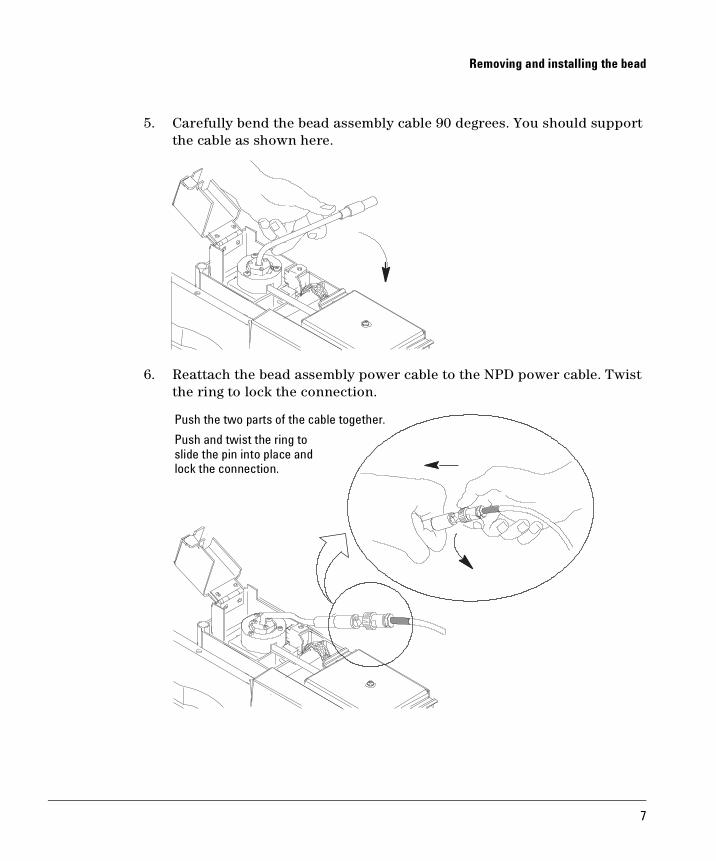
5. Carefully bend the bead assembly cable 90 degrees. You should support the cable as shown here.
6. Reattach the bead assembly power cable to the NPD power cable. Twist the ring to lock the connection.
3
2
Push the two parts of the cable together.
Push and twist the ring toslide the pin into place andlock the connection.
7

Restoring the GC to operating condition
Restoring the GC to operating condition1. Close the NPD cover.
2. Close the GC detector cover.
3. Replace the electronics top cover. You must close all four covers to get a stable NPD baseline.
4. Heat the detector to 150°C for about 15 minutes. Then increase the temperature to the operating value (325 to 335°C recommended). Allow 15 minutes for equilibration.
5. Set Equilibration time to 0.0. Either start Adjust offset or gradually raise the bead voltage, about 0.01 volts at a time, until the baseline increases to the desired offset (usually 30 to 35 pA).
8


Printed on recycled paper.
This product is recyclable.
Agilent Technologies, Inc.
Printed in USA APR 2001
G1534-90317