instruction encoding - howard huanghowardhuang.us/teaching/cs231/19-instruction-encoding.pdf ·...
TRANSCRIPT
July 29, 2003 ©2000-2003 Howard Huang 1
Instruction encoding
We’ve already seen some important aspects of processor design.— A datapath contains an ALU, registers and memory.— Programmers and compilers use instruction sets to issue commands.
This week we’ll complete our processor with a control unit that converts assembly language instructions into the correct datapath signals.— Today we’ll see how assembly instructions can be stored in a binary
format, suitable for hardware manipulation.— Tomorrow we’ll show all of the implementation details for our sample
datapath and assembly language.

July 29, 2003 Instruction encoding 2
Datapath review
The datapath contains all of the circuitry and memory to do a variety of computations.The actual computations are determined by the various datapath control inputs in red.— AA, BA and MB select the
sources for operations.— FS picks an ALU function. — MW = 1 to write to RAM. — MD, WR and DA allow data
to be written back to the register file.
The status bits V, C, N and Zprovide further information about the ALU output.
D
Register file
A B
WR
DA
AA BA
A B
ALU
F
FSVCNZ
1 0Mux B
MB
0 1Mux D
MD
ADRS DATA
Data RAM
OUT
MW
constant
July 29, 2003 Instruction encoding 3
Instruction set review
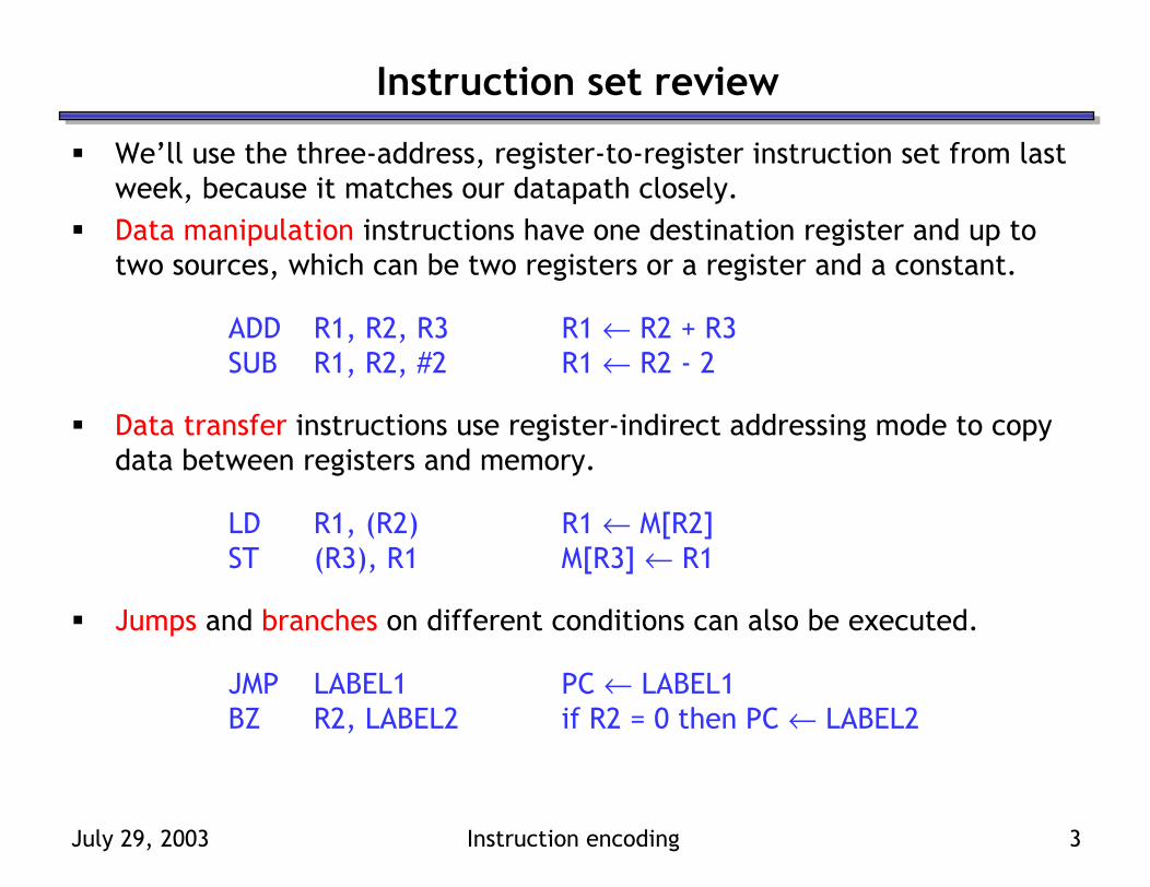
We’ll use the three-address, register-to-register instruction set from last week, because it matches our datapath closely.Data manipulation instructions have one destination register and up to two sources, which can be two registers or a register and a constant.
ADD R1, R2, R3 R1 ← R2 + R3SUB R1, R2, #2 R1 ← R2 - 2
Data transfer instructions use register-indirect addressing mode to copy data between registers and memory.
LD R1, (R2) R1 ← M[R2]ST (R3), R1 M[R3] ← R1
Jumps and branches on different conditions can also be executed.
JMP LABEL1 PC ← LABEL1BZ R2, LABEL2 if R2 = 0 then PC ← LABEL2
July 29, 2003 Instruction encoding 4
From assembly to machine language
We already saw how many types of data are represented with 0s and 1s.— Unsigned numbers are stored as their binary equivalents.— Signed numbers are represented using two’s-complement.— Text is stored as sequences of ASCII values.
Today we’ll show how assembly language instructions can be represented in a binary machine language format.The idea of representing programs in binary and storing them in memory, due to Alan Turing, is what permits computers to perform different tasks easily, just by loading different programs.Go ahead, ask about the apples.

July 29, 2003 Instruction encoding 5
Instruction fields
SUB R1, R2, #2JMP LABEL1BZ R2, LABEL2
Each assembly language instruction contains several components.— An operation, such as SUB and BZ.— Some instructions include a destination register, like R1.— There may be one or two source operands, such as R2 and #2.— Branches and jumps include an address, like LABEL1 and LABEL2.
We can encode an assembly instruction in binary by encoding each of the components, or fields, separately.
July 29, 2003 Instruction encoding 6
Instruction formats
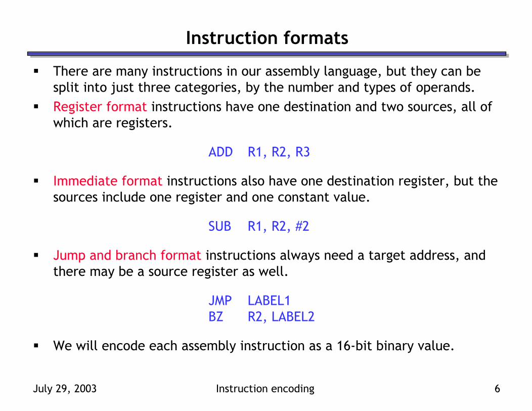
There are many instructions in our assembly language, but they can be split into just three categories, by the number and types of operands.Register format instructions have one destination and two sources, all of which are registers.
ADD R1, R2, R3
Immediate format instructions also have one destination register, but the sources include one register and one constant value.
SUB R1, R2, #2
Jump and branch format instructions always need a target address, and there may be a source register as well.
JMP LABEL1BZ R2, LABEL2
We will encode each assembly instruction as a 16-bit binary value.

July 29, 2003 Instruction encoding 7
Register format
Source Register B
(SB)
Source Register A
(SA)
Destination Register
(DR)Opcode
2 05 38 615 9
An example register-format instruction follows.
ADD R1, R2, R3
Our binary representation for these instructions will include three fields.— A 7-bit opcode field that specifies the operation (e.g., ADD).— A 3-bit destination register, DR (e.g., R1).— Two 3-bit source registers, SA and SB (e.g., R2 and R3).
July 29, 2003 Instruction encoding 8
Immediate format
Operand(OP)
Source Register A
(SA)
Destination Register
(DR)Opcode
2 05 38 615 9
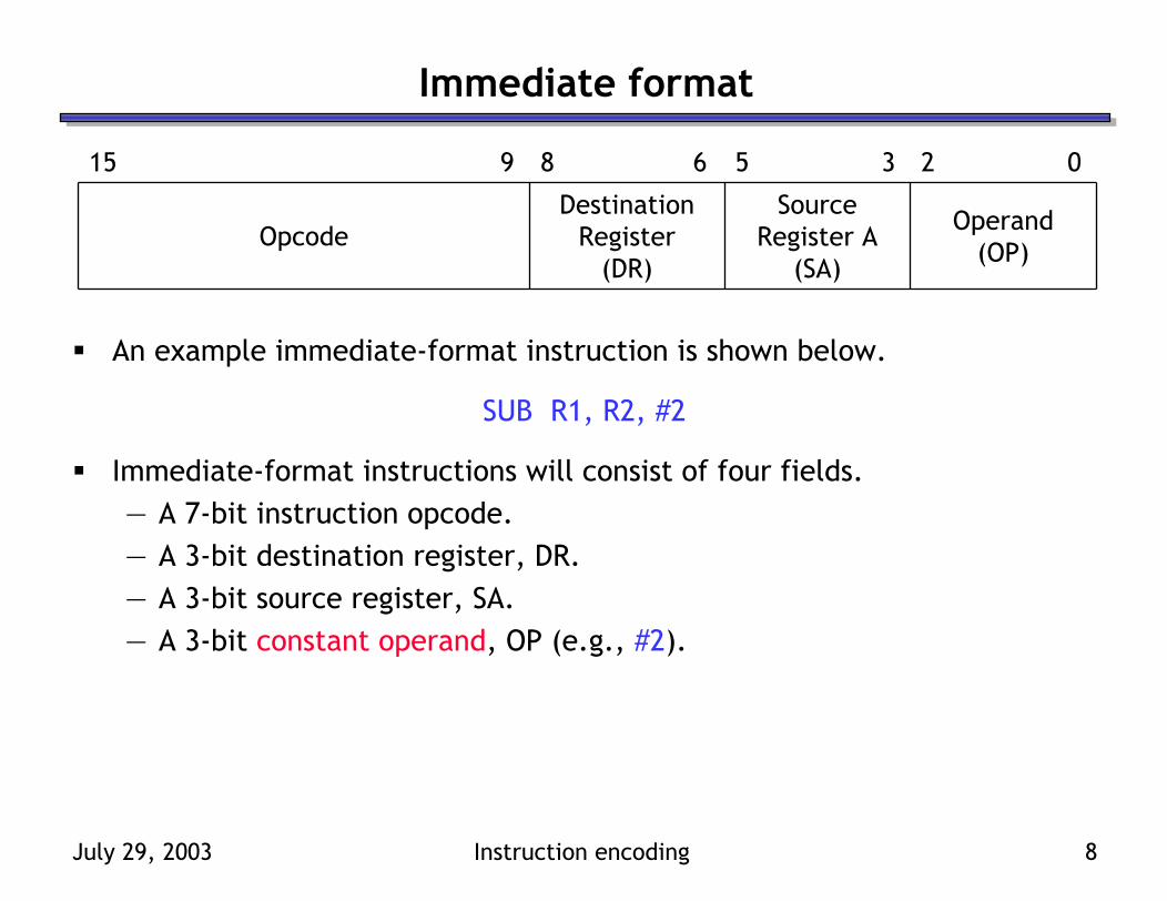
An example immediate-format instruction is shown below.
SUB R1, R2, #2
Immediate-format instructions will consist of four fields.— A 7-bit instruction opcode.— A 3-bit destination register, DR.— A 3-bit source register, SA.— A 3-bit constant operand, OP (e.g., #2).
July 29, 2003 Instruction encoding 9
PC-relative jumps and branches
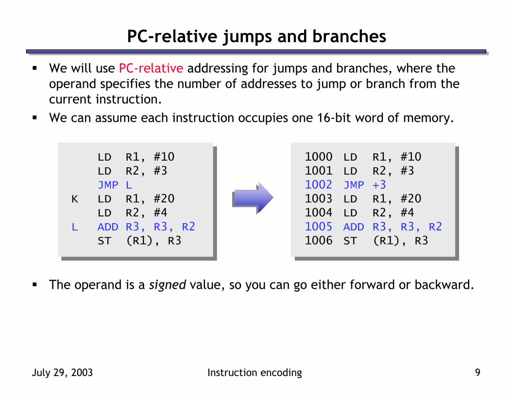
We will use PC-relative addressing for jumps and branches, where the operand specifies the number of addresses to jump or branch from the current instruction.We can assume each instruction occupies one 16-bit word of memory.
The operand is a signed value, so you can go either forward or backward.
LD R1, #10 1000 LD R1, #10LD R2, #3 1001 LD R2, #3JMP L 1002 JMP +3
K LD R1, #20 1003 LD R1, #20LD R2, #4 1004 LD R2, #4
L ADD R3, R3, R2 1005 ADD R3, R3, R2ST (R1), R3 1006 ST (R1), R3
July 29, 2003 Instruction encoding 10
Jump and branch format
AddressBits 2-0 (AD)
Source Register A
(SA)
AddressBits 5-3 (AD)
Opcode
2 05 38 615 9
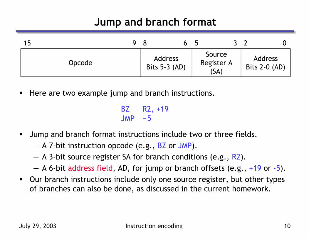
Here are two example jump and branch instructions.
BZ R2, +19JMP -5
Jump and branch format instructions include two or three fields.— A 7-bit instruction opcode (e.g., BZ or JMP).— A 3-bit source register SA for branch conditions (e.g., R2).— A 6-bit address field, AD, for jump or branch offsets (e.g., +19 or -5).
Our branch instructions include only one source register, but other types of branches can also be done, as discussed in the current homework.
July 29, 2003 Instruction encoding 11
The address field AD
AddressBits 2-0 (AD)
Source Register A
(SA)
AddressBits 5-3 (AD)
Opcode
2 05 38 615 9
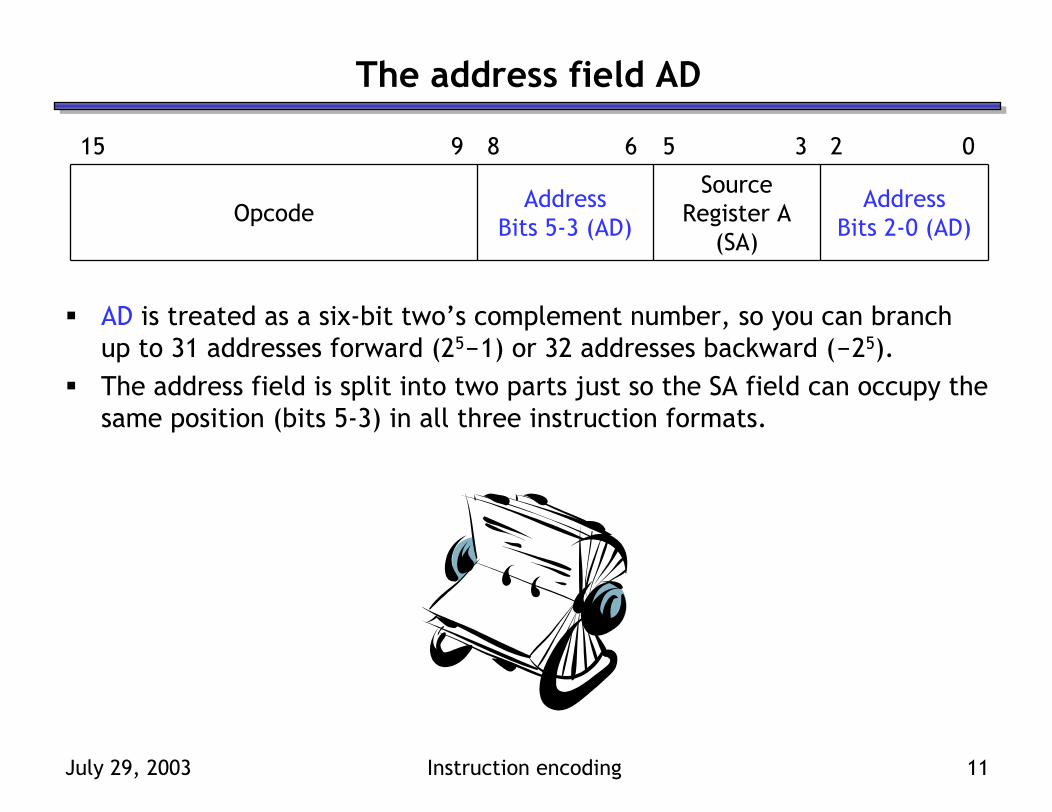
AD is treated as a six-bit two’s complement number, so you can branch up to 31 addresses forward (25-1) or 32 addresses backward (-25).The address field is split into two parts just so the SA field can occupy the same position (bits 5-3) in all three instruction formats.
July 29, 2003 Instruction encoding 12
Instruction format uniformity
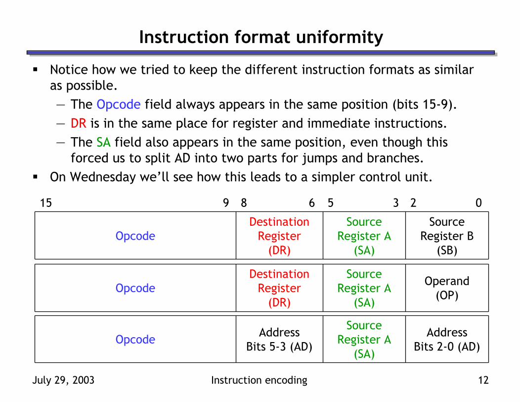
Notice how we tried to keep the different instruction formats as similar as possible.— The Opcode field always appears in the same position (bits 15-9).— DR is in the same place for register and immediate instructions.— The SA field also appears in the same position, even though this
forced us to split AD into two parts for jumps and branches.On Wednesday we’ll see how this leads to a simpler control unit.
Source Register B
(SB)
Source Register A
(SA)
Destination Register
(DR)Opcode
2 05 38 615 9
Operand(OP)
Source Register A
(SA)
Destination Register
(DR)Opcode
AddressBits 2-0 (AD)
Source Register A
(SA)
AddressBits 5-3 (AD)
Opcode
July 29, 2003 Instruction encoding 13
Instruction formats and the datapath
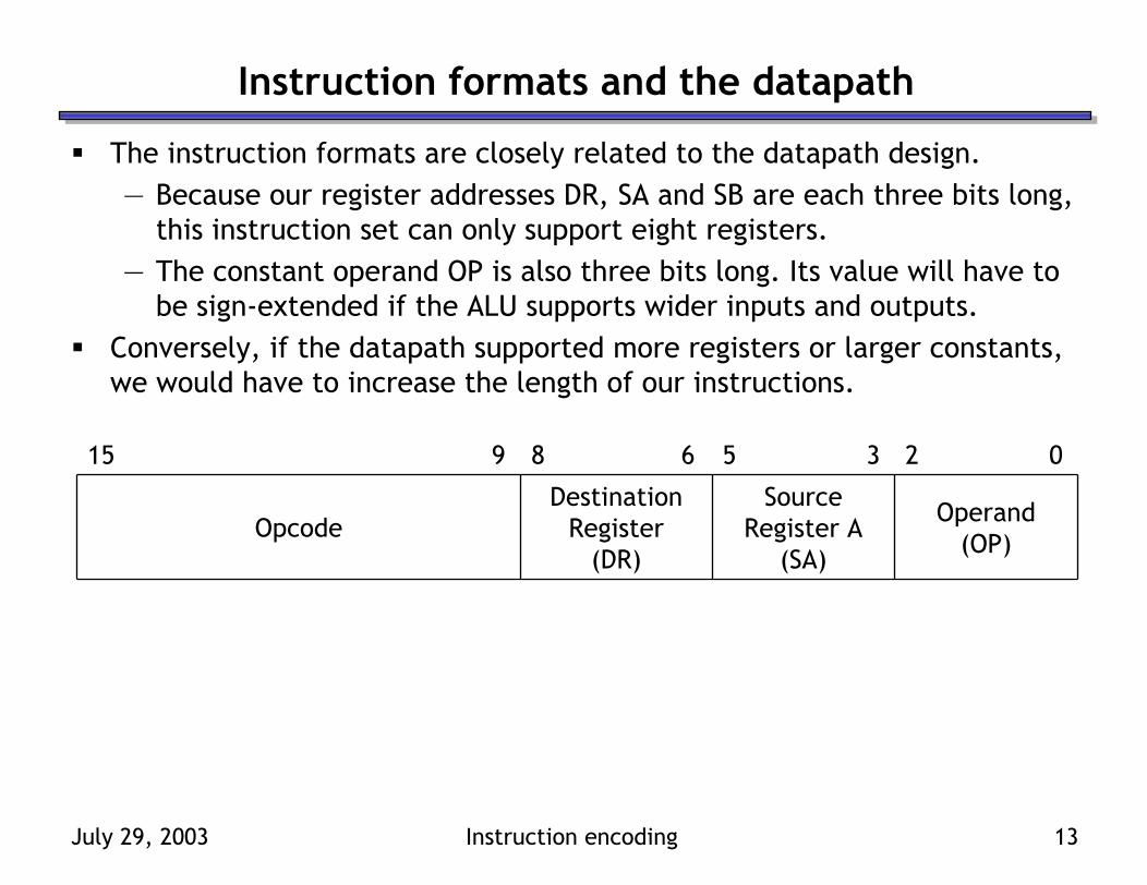
The instruction formats are closely related to the datapath design.— Because our register addresses DR, SA and SB are each three bits long,
this instruction set can only support eight registers.— The constant operand OP is also three bits long. Its value will have to
be sign-extended if the ALU supports wider inputs and outputs.Conversely, if the datapath supported more registers or larger constants, we would have to increase the length of our instructions.
Operand(OP)
Source Register A
(SA)
Destination Register
(DR)Opcode
2 05 38 615 9
July 29, 2003 Instruction encoding 14
Filling in the operand fields
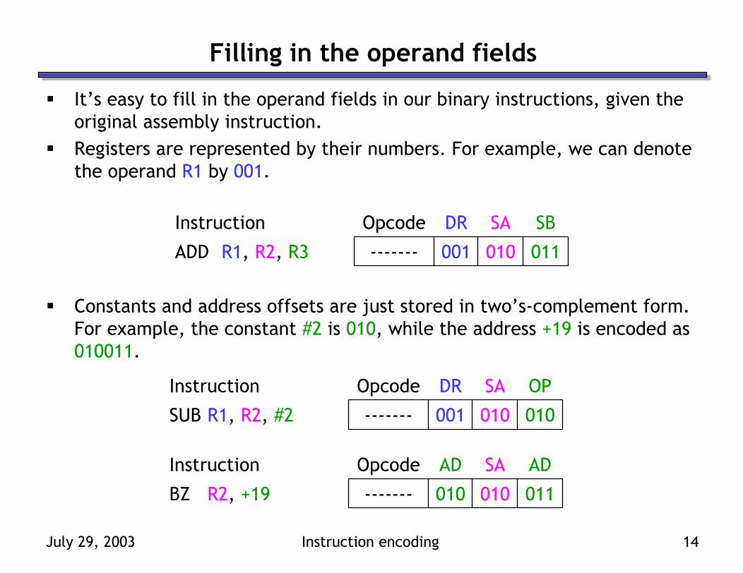
It’s easy to fill in the operand fields in our binary instructions, given the original assembly instruction.Registers are represented by their numbers. For example, we can denote the operand R1 by 001.
Constants and address offsets are just stored in two’s-complement form. For example, the constant #2 is 010, while the address +19 is encoded as 010011.
SBSADROpcodeInstruction
011010001-------ADD R1, R2, R3
OPSADROpcodeInstruction
010010001-------SUB R1, R2, #2
ADSAADOpcodeInstruction
011010010-------BZ R2, +19
July 29, 2003 Instruction encoding 15
Filling in the opcode fields
The hard part is mapping operations like ADD and BZ to binary opcodes!One solution is to just select a random code for each possible operation.— This is (more or less) what we’ll do for the last assignment, MP4.— However, the selection of opcodes can have a significant impact on
the complexity of the processor, much like the assignment of states in sequential circuit design.
Today we’ll see a more methodical approach to assigning opcodes.— Similar operations will have similar opcodes.— This will make our hardware much simpler in Wednesday’s lecture.
Unfortunately you’ll have to understand Wednesday’s material to fully appreciate some of the opcode selection choices we make today.
July 29, 2003 Instruction encoding 16
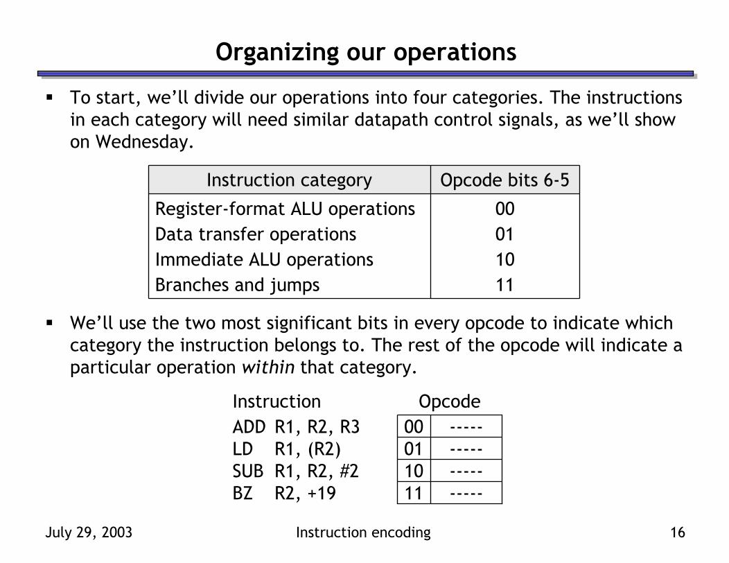
Organizing our operations
To start, we’ll divide our operations into four categories. The instructions in each category will need similar datapath control signals, as we’ll show on Wednesday.
We’ll use the two most significant bits in every opcode to indicate which category the instruction belongs to. The rest of the opcode will indicate a particular operation within that category.
11100100
Opcode bits 6-5
Branches and jumpsImmediate ALU operationsData transfer operationsRegister-format ALU operations
Instruction category
--------------------
10SUB R1, R2, #211BZ R2, +19
01LD R1, (R2)00ADD R1, R2, R3
OpcodeInstruction

July 29, 2003 Instruction encoding 17
Immediate and register-based ALU operations
For both register and immediate ALU operations, a simple approach is to fill in the rest of the opcode bits with the matching ALU function selection code.For example, a register-based XOR would have the opcode 0001100.— The first two bits 00 denote a register-
based ALU instruction.— 01100 denotes the ALU’s add function.
Here are two other examples.
F = sl B (shift left)11000F = sr B (shift right)10100F = B10000F = A’01110F = A ⊕ B01100F = A ∨ B (OR)01010F = A ∧ B (AND)01000F = A00111F = A – 100110F = A + B’ + 100101F = A + B’00100F = A + B + 100011F = A + B00010F = A + 100001F = A00000
OperationFS
0010100010
10SUB R1, R2, #200ADD R1, R2, R3
OpcodeInstruction
July 29, 2003 Instruction encoding 18
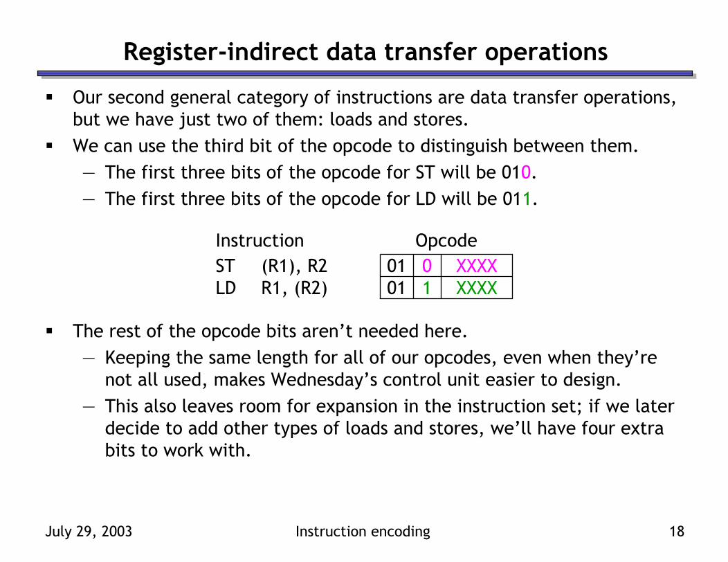
Register-indirect data transfer operations
Our second general category of instructions are data transfer operations, but we have just two of them: loads and stores.We can use the third bit of the opcode to distinguish between them.— The first three bits of the opcode for ST will be 010.— The first three bits of the opcode for LD will be 011.
The rest of the opcode bits aren’t needed here.— Keeping the same length for all of our opcodes, even when they’re
not all used, makes Wednesday’s control unit easier to design.— This also leaves room for expansion in the instruction set; if we later
decide to add other types of loads and stores, we’ll have four extra bits to work with.
10
XXXXXXXX
01LD R1, (R2)01ST (R1), R2
OpcodeInstruction
July 29, 2003 Instruction encoding 19
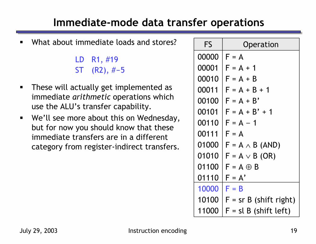
Immediate-mode data transfer operations
What about immediate loads and stores?
LD R1, #19ST (R2), #-5
These will actually get implemented as immediate arithmetic operations which use the ALU’s transfer capability.We’ll see more about this on Wednesday, but for now you should know that these immediate transfers are in a different category from register-indirect transfers.
F = sl B (shift left)11000F = sr B (shift right)10100F = B10000F = A’01110F = A ⊕ B01100F = A ∨ B (OR)01010F = A ∧ B (AND)01000F = A00111F = A – 100110F = A + B’ + 100101F = A + B’00100F = A + B + 100011F = A + B00010F = A + 100001F = A00000
OperationFS

July 29, 2003 Instruction encoding 20
Jump instructions
Our last category included jump and branch instructions.Just as for data transfer instructions, we’ll use one additional opcode bit to distinguish between jumps and branches.— Branch opcodes will all start with the three bits 110.— Jump opcodes will start with the bits 111.
Our instruction set has only one PC-relative jump instruction so the rest of the opcode bits are unused, much like for loads and stores.
10
XXXX----
11JMP -511BZ R2, +19
OpcodeInstruction
July 29, 2003 Instruction encoding 21
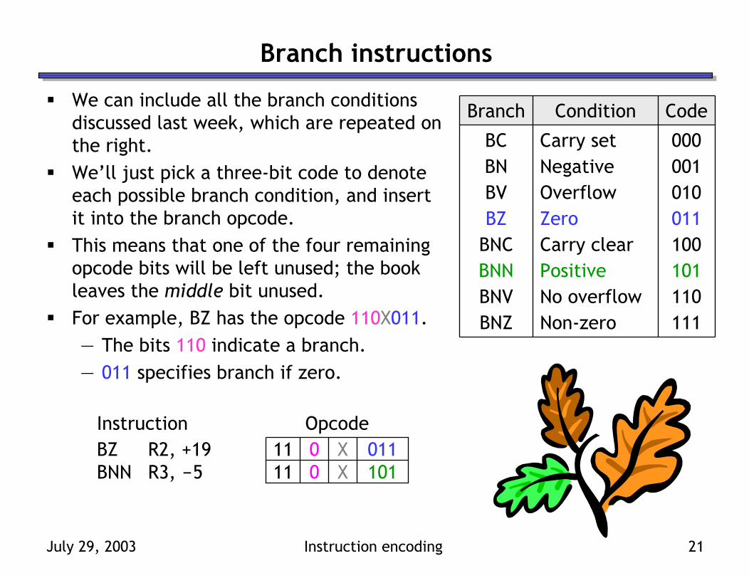
Branch instructions
We can include all the branch conditions discussed last week, which are repeated on the right.We’ll just pick a three-bit code to denote each possible branch condition, and insert it into the branch opcode.This means that one of the four remaining opcode bits will be left unused; the book leaves the middle bit unused.For example, BZ has the opcode 110X011.— The bits 110 indicate a branch.— 011 specifies branch if zero.
BNZBNVBNNBNCBZBVBNBC
Branch
111Non-zero110No overflow101Positive100Carry clear011Zero010Overflow001Negative000Carry set
CodeCondition
101011
00
XX
11BNN R3, -511BZ R2, +19
OpcodeInstruction
July 29, 2003 Instruction encoding 22
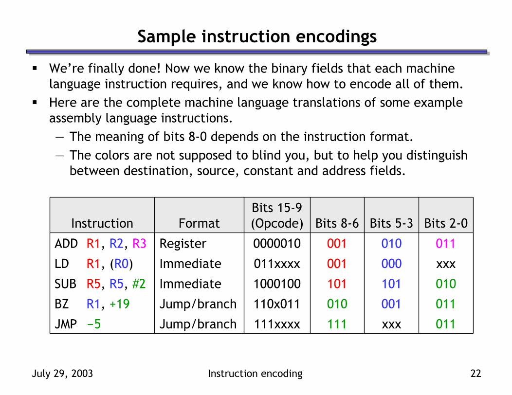
Sample instruction encodings
We’re finally done! Now we know the binary fields that each machine language instruction requires, and we know how to encode all of them.Here are the complete machine language translations of some example assembly language instructions.— The meaning of bits 8-0 depends on the instruction format.— The colors are not supposed to blind you, but to help you distinguish
between destination, source, constant and address fields.
011001010110x011Jump/branchBZ R1, +19
0110100010000010RegisterADD R1, R2, R3
011xxx111111xxxxJump/branchJMP -5
0101011011000100ImmediateSUB R5, R5, #2
xxx000001011xxxxImmediateLD R1, (R0)
Bits 2-0Bits 5-3Bits 8-6Bits 15-9 (Opcode)FormatInstruction

July 29, 2003 Instruction encoding 23
Summary
Today we defined a binary machine language for the instruction set from last Wednesday.— Each assembly language instruction contains several component fields.— Different instructions are encoded using different binary formats, but
keeping those formats uniform will help simplify our hardware.— We also tried to assign similar opcodes to “similar” instructions.— Register, constant and address offset operands are represented as just
unsigned or signed binary numbers.This instruction encoding is closely related to our example datapath. For example, our opcodes include ALU function selection codes, and the number of usable registers is limited by the length of each instruction.This is just one example of how to define a machine language. You will be using a different instruction encoding for MP4, for instance.Tomorrow we’ll show how to build a control unit that corresponds to our datapath and instruction set. This will complete our processor!