instruction - campbell sci · or faxed to (435) 227-9106. campbell scientific is unable to process...
TRANSCRIPT

CS511 Dissolved Oxygen Sensor
Revision: 5/18 Copyright © 2001 – 2018 Campbell Scientific, Inc.


Limited Warranty “Products manufactured by CSI are warranted by CSI to be free from defects in materials and workmanship under normal use and service for twelve months from the date of shipment unless otherwise specified in the corresponding product manual. (Product manuals are available for review online at www.campbellsci.com.) Products not manufactured by CSI, but that are resold by CSI, are warranted only to the limits extended by the original manufacturer. Batteries, fine-wire thermocouples, desiccant, and other consumables have no warranty. CSI’s obligation under this warranty is limited to repairing or replacing (at CSI’s option) defective Products, which shall be the sole and exclusive remedy under this warranty. The Customer assumes all costs of removing, reinstalling, and shipping defective Products to CSI. CSI will return such Products by surface carrier prepaid within the continental United States of America. To all other locations, CSI will return such Products best way CIP (port of entry) per Incoterms ® 2010. This warranty shall not apply to any Products which have been subjected to modification, misuse, neglect, improper service, accidents of nature, or shipping damage. This warranty is in lieu of all other warranties, expressed or implied. The warranty for installation services performed by CSI such as programming to customer specifications, electrical connections to Products manufactured by CSI, and Product specific training, is part of CSI's product warranty. CSI EXPRESSLY DISCLAIMS AND EXCLUDES ANY IMPLIED WARRANTIES OF MERCHANTABILITY OR FITNESS FOR A PARTICULAR PURPOSE. CSI hereby disclaims, to the fullest extent allowed by applicable law, any and all warranties and conditions with respect to the Products, whether express, implied or statutory, other than those expressly provided herein.”

Assistance Products may not be returned without prior authorization. The following contact information is for US and international customers residing in countries served by Campbell Scientific, Inc. directly. Affiliate companies handle repairs for customers within their territories. Please visit www.campbellsci.com to determine which Campbell Scientific company serves your country.
To obtain a Returned Materials Authorization (RMA) number, contact CAMPBELL SCIENTIFIC, INC., phone (435) 227-9000. Please write the issued RMA number clearly on the outside of the shipping container. Campbell Scientific’s shipping address is:
CAMPBELL SCIENTIFIC, INC. RMA#_____ 815 West 1800 North Logan, Utah 84321-1784
For all returns, the customer must fill out a “Statement of Product Cleanliness and Decontamination” form and comply with the requirements specified in it. The form is available from our website at www.campbellsci.com/repair. A completed form must be either emailed to [email protected] or faxed to (435) 227-9106. Campbell Scientific is unable to process any returns until we receive this form. If the form is not received within three days of product receipt or is incomplete, the product will be returned to the customer at the customer’s expense. Campbell Scientific reserves the right to refuse service on products that were exposed to contaminants that may cause health or safety concerns for our employees.

Safety DANGER — MANY HAZARDS ARE ASSOCIATED WITH INSTALLING, USING, MAINTAINING, AND WORKING ON OR AROUND TRIPODS, TOWERS, AND ANY ATTACHMENTS TO TRIPODS AND TOWERS SUCH AS SENSORS, CROSSARMS, ENCLOSURES, ANTENNAS, ETC. FAILURE TO PROPERLY AND COMPLETELY ASSEMBLE, INSTALL, OPERATE, USE, AND MAINTAIN TRIPODS, TOWERS, AND ATTACHMENTS, AND FAILURE TO HEED WARNINGS, INCREASES THE RISK OF DEATH, ACCIDENT, SERIOUS INJURY, PROPERTY DAMAGE, AND PRODUCT FAILURE. TAKE ALL REASONABLE PRECAUTIONS TO AVOID THESE HAZARDS. CHECK WITH YOUR ORGANIZATION'S SAFETY COORDINATOR (OR POLICY) FOR PROCEDURES AND REQUIRED PROTECTIVE EQUIPMENT PRIOR TO PERFORMING ANY WORK.
Use tripods, towers, and attachments to tripods and towers only for purposes for which they are designed. Do not exceed design limits. Be familiar and comply with all instructions provided in product manuals. Manuals are available at www.campbellsci.com or by telephoning (435) 227-9000 (USA). You are responsible for conformance with governing codes and regulations, including safety regulations, and the integrity and location of structures or land to which towers, tripods, and any attachments are attached. Installation sites should be evaluated and approved by a qualified engineer. If questions or concerns arise regarding installation, use, or maintenance of tripods, towers, attachments, or electrical connections, consult with a licensed and qualified engineer or electrician.
General • Prior to performing site or installation work, obtain required approvals and permits. Comply
with all governing structure-height regulations, such as those of the FAA in the USA. • Use only qualified personnel for installation, use, and maintenance of tripods and towers, and
any attachments to tripods and towers. The use of licensed and qualified contractors is highly recommended.
• Read all applicable instructions carefully and understand procedures thoroughly before beginning work.
• Wear a hardhat and eye protection, and take other appropriate safety precautions while working on or around tripods and towers.
• Do not climb tripods or towers at any time, and prohibit climbing by other persons. Take reasonable precautions to secure tripod and tower sites from trespassers.
• Use only manufacturer recommended parts, materials, and tools.
Utility and Electrical • You can be killed or sustain serious bodily injury if the tripod, tower, or attachments you are
installing, constructing, using, or maintaining, or a tool, stake, or anchor, come in contact with overhead or underground utility lines.
• Maintain a distance of at least one-and-one-half times structure height, 20 feet, or the distance required by applicable law, whichever is greater, between overhead utility lines and the structure (tripod, tower, attachments, or tools).
• Prior to performing site or installation work, inform all utility companies and have all underground utilities marked.
• Comply with all electrical codes. Electrical equipment and related grounding devices should be installed by a licensed and qualified electrician.
Elevated Work and Weather • Exercise extreme caution when performing elevated work. • Use appropriate equipment and safety practices. • During installation and maintenance, keep tower and tripod sites clear of un-trained or non-
essential personnel. Take precautions to prevent elevated tools and objects from dropping. • Do not perform any work in inclement weather, including wind, rain, snow, lightning, etc.
Maintenance • Periodically (at least yearly) check for wear and damage, including corrosion, stress cracks,
frayed cables, loose cable clamps, cable tightness, etc. and take necessary corrective actions. • Periodically (at least yearly) check electrical ground connections.
WHILE EVERY ATTEMPT IS MADE TO EMBODY THE HIGHEST DEGREE OF SAFETY IN ALL CAMPBELL SCIENTIFIC PRODUCTS, THE CUSTOMER ASSUMES ALL RISK FROM ANY INJURY RESULTING FROM IMPROPER INSTALLATION, USE, OR MAINTENANCE OF TRIPODS, TOWERS, OR ATTACHMENTS TO TRIPODS AND TOWERS SUCH AS SENSORS, CROSSARMS, ENCLOSURES, ANTENNAS, ETC.


i
Table of Contents PDF viewers: These page numbers refer to the printed version of this document. Use the PDF reader bookmarks tab for links to specific sections.
1. Introduction ................................................................ 1
2. Precautions ................................................................ 1
3. Initial Inspection ......................................................... 1
3.1 Shipping Kit ......................................................................................... 1
4. QuickStart ................................................................... 2
5. Overview ..................................................................... 3
6. Specifications ............................................................. 4
7. Installation .................................................................. 5
7.1 Getting Sensor Ready to Use ............................................................... 6 7.2 Mount Sensor ....................................................................................... 7 7.3 Wiring to the Datalogger ...................................................................... 7 7.4 Programming ........................................................................................ 8 7.5 Calibration............................................................................................ 8
8. Maintenance ............................................................... 9
8.1 Cleaning Sensor and Replacing Membrane ....................................... 10
Appendices
A. Importing Short Cut Code Into CRBasic Editor ... A-1
B. Example Programs ................................................. B-1
B.1 VoltDiff CR1000X Example............................................................ B-1 B.2 VoltSE CR200(X) Program ............................................................. B-2
C. Dissolved Oxygen Tables ...................................... C-1
C.1 Dissolved Oxygen in Fresh Water ................................................... C-1 C.2 Dissolved Oxygen in Salt Water ...................................................... C-2
Figures 8-1. Separate the lower body from the upper body ................................... 10 8-2. Remove membrane and membrane O-ring ........................................ 11 8-3. Using a toothbrush to clean sensor ..................................................... 12 8-4. Proper O-ring placement .................................................................... 12

Table of Contents
ii
8-5. Installing membrane .......................................................................... 13 8-6. Check for leakage .............................................................................. 14
Tables 7-1. CS511 Wire Color, Function, and Datalogger Connection ................. 8 B-1. Wiring for CR1000X Example ........................................................ B-1 B-2. Wiring for CR200(X) Example ....................................................... B-2
CRBasic Examples B-1. VoltDiff CR1000X Example ........................................................... B-1 B-2. VoltSE CR200(X) Program ............................................................. B-2

1
CS511 Dissolved Oxygen Sensor 1. Introduction
The CS511 is a rugged, low-maintenance sensor that is manufactured by Sensorex. It consists of a self-polarizing galvanic cell that generates a millivolt signal proportional to the amount of oxygen present in the measured medium (typically water).
This manual provides information only for CRBasic dataloggers. For retired Edlog datalogger support, see a retired manual at www.campbellsci.com\old-manuals. Also refer to a retired manual if the CS511 was purchased before June 2008 and for information on using the retired PT4-L Agitator.
2. Precautions • READ AND UNDERSTAND the Safety section at the front of this
manual.
• The CS511 is a precision instrument. Please handle it with care.
• Because the CS511 is shipped dry, electrolyte needs to be added before using the sensor (Section 7.1, Getting Sensor Ready to Use (p. 6)).
• Letting the CS511 dry in the field shortens the life of the membrane and sensor.
• The sensor should be stored dry and empty. Therefore, empty the electrolyte, rinse the sensor, and remove the membrane.
• Replace the membrane and recalibrate the sensor before redeploying the CS511 after it has been stored out of water or dried up in the field.
3. Initial Inspection • Upon receipt of the CS511, inspect the packaging and contents for
damage. File damage claims with the shipping company.
• Immediately check package contents against the shipping documentation (see Section 3.1, Shipping Kit (p. 1)). Contact Campbell Scientific about any discrepancies.
• The model number and cable length are printed on a label at the connection end of the cable. Check this information against the shipping documents to ensure the expected product and cable length were received.
3.1 Shipping Kit The CS511 ships with:
(1) Membrane replacement tool (1) Bottled electrolyte, 250 ml (2) Teflon membranes (2) Membrane O-rings
NOTE

CS511 Dissolved Oxygen Sensor
2
4. QuickStart A video that describes datalogger programming using Short Cut is available at: www.campbellsci.com/videos/cr1000x-datalogger-getting-started-program-part-3. Short Cut is an easy way to program your datalogger to measure the sensor and assign datalogger wiring terminals. Short Cut is available as a download on www.campbellsci.com. It is included in installations of LoggerNet, PC200W, PC400, or RTDAQ.
The following procedure also describes using Short Cut to program the CS511.
1. Open Short Cut and click Create New Program.
2. Double-click the datalogger model.
3. In the Available Sensors and Devices box, type CS511, or locate the sensor in the Sensors | Water | Quality folder. Double-click CS511 Dissolved Oxygen Probe. The default calibration value of 0.34 is based on an average. It is preferable to calibrate the sensor by using the procedure provided in Section 7.5, Calibration (p. 8). Click on the Wiring tab to see how the sensor is to be wired to the datalogger.

CS511 Dissolved Oxygen Sensor
3
4. Repeat step three for other sensors.
5. In Output Setup, type the scan rate, meaningful table names, and the Data Output Storage Interval.
6. Select the measurement and its associated output options.
7. Click Finish and save the program. Send the program to the datalogger if the datalogger is connected to the computer.
8. If the sensor is connected to the datalogger, check the output of the sensor in the data display in LoggerNet, PC400, RTDAQ, or PC200W to make sure it is making reasonable measurements.
5. Overview The CS511 is a galvanic sensor, which produces a millivolt signal proportional to the amount of oxygen present in the measured medium. Oxygen diffuses through the membrane onto the cathode, reacts chemically, and combines with the anode. An electrical current is produced by this chemical reaction which is converted from microamps to millivolts by an in-line resistor. An in-line thermistor also conditions the signal providing automatic temperature

CS511 Dissolved Oxygen Sensor
4
compensation. With these features, the sensor produces a linear, millivolt output proportional to the oxygen present in the medium in which it is placed.
The sensor consists of two parts, an upper part with cathode, anode, and cable, and a lower part comprising of a screw-on membrane cap. The CS511 is shipped dry, but has a membrane installed in the cap. With the membrane in place, the cap must be filled with electrolyte solution before the cap is screwed onto the top component.
The CS511 is self-polarizing and requires no external power source.
6. Specifications Features:
• In-line thermistor provides automatic temperature compensation • Compatible with the following CRBasic dataloggers: CR200(X)
series, CR300 series, CR6 series, CR800 series, CR1000, CR1000X series, CR3000, CR5000, and CR9000(X)
Principle of Measurement: Membrane-covered, galvanic oxygen sensor
Output Signal: 33 mV ± 9 mV (100% saturation), < 2 mV (0% saturation)
Accuracy: Better than ± 2% of reading ± 1 digit when calibration temperature equals measuring temperature ± 5 °C
Response Time: 5 min. from 100% to 0% oxygen
Materials of Construction Body: Anode: Cathode:
Noryl Zinc Silver
Diameter: 5.72 cm (2.25 in)
Height: 17.78 cm (7 in) from bottom of sensor to end of cable-strain relief
Shipping Weight 0.8 kg (1.75 lb)
Cable Jacket Material: PVC
Operating Conditions Temperature: Pressure: Minimum Submersion Depth: Minimum Water Flow:
0 to 50 °C (32 to 122 °F) 0 to 100 psig 60 mm (2.5 in) 5 cm/s (2 inch/s) across membrane
Calibration: In air or in air saturated water

CS511 Dissolved Oxygen Sensor
5
Temperature Compensation: Automatic from 4 to 40 °C (40 to 104 °F)
Range of Dissolved Oxygen: 0.5 to 50 ppm
Sensor Electrolyte: NaCl + glycerol (prevents freezing)
7. Installation If you are programming your datalogger with Short Cut, skip Section 7.3, Wiring to the Datalogger (p. 7), and Section 7.4, Programming (p. 8). Short Cut does this work for you. See Section 4, QuickStart (p. 2), for a Short Cut tutorial.

CS511 Dissolved Oxygen Sensor
6
7.1 Getting Sensor Ready to Use 1. Unscrew the lower body from the upper body.
2. Inspect the membrane for wrinkles. Replace membrane if wrinkled (see Section 8.1, Cleaning Sensor and Replacing Membrane (p. 10)).
3. Pour clean water into the lower body and look for leakage around the membrane. Dispose of the water, and if there is leakage, replace membrane (see Section 8.1, Cleaning Sensor and Replacing Membrane (p. 10)).

CS511 Dissolved Oxygen Sensor
7
4. Pour fresh electrolyte in the bottom cap and fill to the top of the cap.
5. Keep the sensor upright with the cable pointed upwards (not sideways). Screw the bottom cap onto the upper body until hand tight.
Excess electrolyte will leak out at the joint between the sensor cap and upper body.
7.2 Mount Sensor Mount the CS511 in water at a slight angle, which prevents bubbles from becoming trapped on the membrane.
7.3 Wiring to the Datalogger Datalogger connection is provided in TABLE 7-1. The CS511 can use one differential terminal or one single-ended terminal. Differential wiring is better at rejecting electrical noise and ground loop error.
NOTE

CS511 Dissolved Oxygen Sensor
8
TABLE 7-1. CS511 Wire Color, Function, and Datalogger Connection
Wire Color
Wire Function
Differential Datalogger Connection
Single-Ended Datalogger Connection
White Signal High
U configured for differential input1, DIFF
H (differential high, analog-voltage input)
U configured for single-ended input1, SE
(single-ended analog-voltage input)
Black Signal Reference
U configured for differential input1, DIFF
L (differential low, analog-voltage input)
⏚ (analog ground)
Clear Shield ⏚ (analog ground) ⏚ (analog ground) 1U terminals are automatically configured by the measurement instruction.
7.4 Programming Short Cut is the best source for up-to-date datalogger programming code.
If your data acquisition requirements are simple, you can probably create and maintain a datalogger program exclusively with Short Cut. If your data acquisition needs are more complex, the files that Short Cut creates are a great source for programming code to start a new program or add to an existing custom program.
Short Cut cannot edit programs after they are imported and edited in CRBasic Editor.
A Short Cut tutorial is available in Section 4, QuickStart (p. 2). If you wish to import Short Cut code into CRBasic Editor to create or add to a customized program, follow the procedure in Appendix A, Importing Short Cut Code Into CRBasic Editor (p. A-1). Programming basics for CRBasic dataloggers are provided in the following sections. Complete program examples for select dataloggers can be found in Appendix B, Example Programs (p. B-1).
The VoltDiff() or VoltSE() can be used to measure the CS511. Choose a voltage range of 100 mV or higher.
7.5 Calibration The multiplier is used to calibrate the CS511 sensor. To calculate the multiplier:
1. Program the datalogger by using a multiplier of one (see Section 4, QuickStart (p. 2), or Section 7.4, Programming (p. 8)).
2. Connect the CS511 to the datalogger (see wiring diagram generated by Short Cut or Section 7.3, Wiring to the Datalogger (p. 7)).
3. If the CS511 has been deployed in the field, gently wipe the membrane with a soft cloth.
NOTE

CS511 Dissolved Oxygen Sensor
9
4. Place the CS511 in air away from direct sunlight with the membrane facing upward.
5. Place a drop of clean water on the membrane.
6. Wait for readings to stabilize. This may take 15 minutes or more.
7. Determine the air temperature and barometric pressure.
8. Using a calibration chart such as that provided in Appendix C, Dissolved Oxygen Tables (p. C-1), determine the oxygen concentration of the air.
9. Use the following equation to calculate the multiplier: M = P/R where: M = Multiplier P = Concentration in PPM of the air (from the calibration chart) R = The signal output of the sensor when using a multiplier of one
10. Change the multiplier in the datalogger program from one to the calculated number (see Section 4, QuickStart (p. 2)), or Section 7.4, Programming (p. 8)).
Instead of step 10, the following expression can be used that allows a new multiplier to be added to the program without rewriting, compiling, and downloading the program to the datalogger.
CRBasic Expression for Entering Multiplier:
DOppm = DOMult * DOmV
With this method, the multiplier value is typed into the expression through the Public Table by using the numeric display in PC200W, LoggerNet, PC400, or datalogger keyboard display.
8. Maintenance Campbell Scientific offers maintenance kits that contain membranes, membrane O-rings, washers, and a bottle of electrolyte. A spare parts kit is also available that contains two membrane locks, two tensioning washers, two body O-rings, and one membrane replacement tool. Refer to www.campbellsci.com/order/cs511-l for more information.
The CS511 uses a strong, easy-to-clean, and easy-to-change membrane in a screw-on membrane cap. The sensor can be fully overhauled in five minutes.
CS511 Dissolved Oxygen Sensor
10
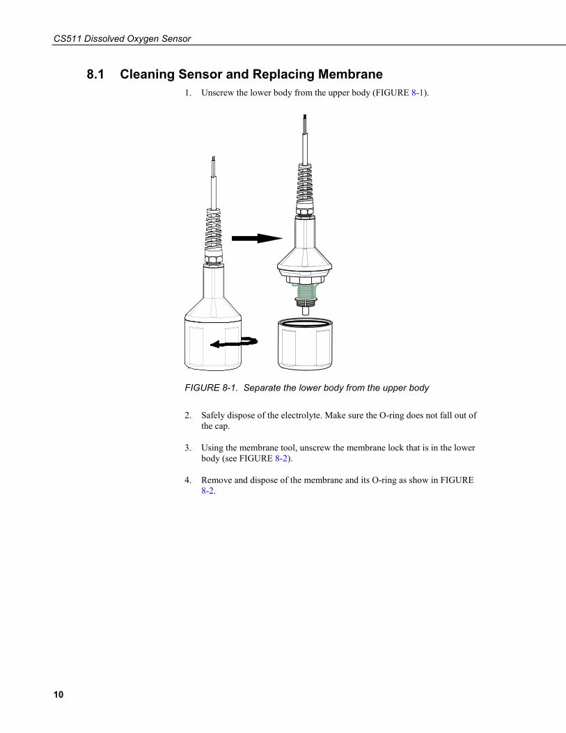
8.1 Cleaning Sensor and Replacing Membrane 1. Unscrew the lower body from the upper body (FIGURE 8-1).
FIGURE 8-1. Separate the lower body from the upper body
2. Safely dispose of the electrolyte. Make sure the O-ring does not fall out of the cap.
3. Using the membrane tool, unscrew the membrane lock that is in the lower body (see FIGURE 8-2).
4. Remove and dispose of the membrane and its O-ring as show in FIGURE 8-2.

CS511 Dissolved Oxygen Sensor
11
FIGURE 8-2. Remove membrane and membrane O-ring
Membrane Lock
Washer
Membrane
Membrane O-ring
Cap O-ring (do not dispose)
Membrane Tool

CS511 Dissolved Oxygen Sensor
12
5. To clean, immerse the top part of the sensor in distilled white vinegar (3% acetic acid) for about 30 minutes. If vinegar is unavailable, use a soft toothbrush, automatic dishwasher detergent, and clean water to clean the cathode, anode, and plastic. Rinse all components thoroughly with clean water after cleaning (see FIGURE 8-3).
FIGURE 8-3. Using a toothbrush to clean sensor
6. Replace the membrane and its O-ring by first placing the new O-ring at the bottom of the membrane cavity (see FIGURE 8-4). Remove the paper backing from a new membrane and place the new membrane on top of the O-ring, and place the washer on top of the membrane. Using the membrane tool, install the membrane lock on top of the washer as shown in FIGURE 8-5. Make sure the cap is upright (not sideways) when securing the membrane lock to the washer.
FIGURE 8-4. Proper O-ring placement

CS511 Dissolved Oxygen Sensor
13
FIGURE 8-5. Installing membrane
7. Inspect the membrane for wrinkles; replace membrane if wrinkled.
Membrane Lock
Washer
Membrane
O-ring
Membrane Tool
CS511 Dissolved Oxygen Sensor
14
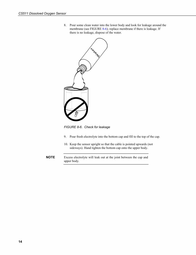
8. Pour some clean water into the lower body and look for leakage around the membrane (see FIGURE 8-6); replace membrane if there is leakage. If there is no leakage, dispose of the water.
FIGURE 8-6. Check for leakage
9. Pour fresh electrolyte into the bottom cap and fill to the top of the cap.
10. Keep the sensor upright so that the cable is pointed upwards (not sideways). Hand tighten the bottom cap onto the upper body.
Excess electrolyte will leak out at the joint between the cap and upper body.
NOTE

A-1
Appendix A. Importing Short Cut Code Into CRBasic Editor
This tutorial shows:
• Importing a Short Cut program into a program editor for additional refinement
• Importing a wiring diagram from Short Cut into the comments of a custom program
Short Cut creates files, which can be imported into CRBasic Editor. Assuming defaults were used when Short Cut was installed, these files reside in the C:\campbellsci\SCWin folder:
• .DEF (wiring and memory usage information) • .CR2 (CR200(X)-series datalogger code) • .CR300 (CR300-series datalogger code) • .CR6 (CR6-series datalogger code) • .CR8 (CR800-series datalogger code) • .CR1 (CR1000 datalogger code) • .CR1X (CR1000X-series datalogger code) • .CR3 (CR3000 datalogger code) • .CR5 (CR5000 datalogger code) • .CR9 (CR9000(X) datalogger code)
Import Short Cut code and wiring diagram into CRBasic Editor:
1. Create the Short Cut program following the procedure in Section 4, QuickStart (p. 2). Finish the program. On the Advanced tab, click the CRBasic Editor button. The program opens in CRBasic with the name noname.CR_. Provide a name and save the program.
Once the file is edited with CRBasic Editor, Short Cut can no longer be used to edit the datalogger program.
2. The program can now be edited, saved, and sent to the datalogger.
3. Import wiring information to the program by opening the associated .DEF file. By default, it is saved in the c:\campbellsci\SCWin folder. Copy and paste the section beginning with heading “–Wiring for CRXXX–” into the CRBasic program, usually at the head of the file. After pasting, edit the information such that an apostrophe (') begins each line. This character instructs the datalogger compiler to ignore the line when compiling. You can highlight several lines of CRBasic code then right-click and select Comment Block. (This feature is demonstrated at about 5:10 in the CRBasic | Features video.)
NOTE


B-1
Appendix B. Example Programs B.1 VoltDiff CR1000X Example
Programming for the CR300 series, CR800, CR850, CR1000, CR3000, and CR5000 is similar to this CR1000X program. TABLE B-1 shows the wiring for the example.
TABLE B-1. Wiring for CR1000X Example
CR1000X Connection Sensor Wire
1H White
1L Black
Ground Clear
CRBasic Example B-1. VoltDiff CR1000X Example
'CR1000X 'Declare Variables and Units Public Batt_Volt Public DOmV Public DOppm Public DOMult Units Batt_Volt=Volts Units DOmV=mV Units DOppm=ppm 'Define Data Tables DataTable(Hourly,True,-1) DataInterval(0,60,Min,10) Sample(1,DOmV,FP2) Sample(1,DOppm,FP2) Sample(1,Batt_Volt,FP2) EndTable DataTable(Daily,True,-1) DataInterval(0,1440,Min,10) Minimum(1,Batt_Volt,FP2,False,False) EndTable 'Main Program BeginProg Scan(5,Sec,1,0) 'Default Datalogger Battery Voltage measurement Batt_Volt: Battery(Batt_Volt) 'CS511 Dissolved Oxygen Sensor measurements DOmV and DOppm: VoltDiff(DOmV,1,mV200,1,True,0,60,1,0) DOppm = DOMult * DOmV 'Call Data Tables and Store Data CallTable(Hourly) CallTable(Daily) NextScan EndProg

Appendix B. Example Programs
B-2
B.2 VoltSE CR200(X) Program The CR200(X)-series must use the VoltSE() instruction since these dataloggers do not make differential measurements. If the other CRBasic dataloggers use the VoltSE() instruction instead of the VoltDiff() instruction, their programming will be similar to this example. TABLE B-2 shows the wiring for the example.
TABLE B-2. Wiring for CR200(X) Example
CR200(X) Connection Sensor Wire
SE1 White
Ground Black
Ground Clear
CRBasic Example B-2. VoltSE CR200(X) Program
'CR200(X) Series 'Declare Variables and Units Public Batt_Volt Public DOmV Public DOppm Public DOMult Units Batt_Volt=Volts Units DOmV=mV Units DOppm=ppm 'Define Data Tables DataTable(Hourly,True,-1) DataInterval(0,60,Min) Sample(1,DOmV) EndTable DataTable(Daily,True,-1) DataInterval(0,1440,Min) Minimum(1,Batt_Volt,False,False) EndTable 'Main Program BeginProg Scan(10,Sec) 'Default Datalogger Battery Voltage measurement Batt_Volt: Battery(Batt_Volt) 'CS511 Dissolved Oxygen Sensor measurements DOmV and DOppm: VoltSE(DOmV,1,1,1,0) DOppm = DOMult * DOmV 'Call Data Tables and Store Data CallTable(Hourly) CallTable(Daily) NextScan EndProg

C-1
Appendix C. Dissolved Oxygen Tables C.1 Dissolved Oxygen in Fresh Water

Appendix C. Dissolved Oxygen Tables
C-2
C.2 Dissolved Oxygen in Salt Water


Campbell Scientific Worldwide Offices
Australia Location: Garbutt, QLD Australia Email: [email protected]
Website: www.campbellsci.com.au
Germany Location: Bremen, Germany Email: [email protected]
Website: www.campbellsci.de
Brazil Location: São Paulo, SP Brazil
Email: [email protected] Website: www.campbellsci.com.br
South Africa Location: Stellenbosch, South Africa
Email: [email protected] Website: www.campbellscientific.co.za
Canada Location: Edmonton, AB Canada
Email: [email protected] Website: www.campbellsci.ca
Southeast Asia Location: Bangkok, Thailand Email: [email protected]
Website: www.campbellsci.asia
China Location: Beijing, P. R. China
Email: [email protected] Website: www.campbellsci.com.cn
Spain Location: Barcelona, Spain Email: [email protected]
Website: www.campbellsci.es
Costa Rica Location: San José, Costa Rica
Email: [email protected] Website: www.campbellsci.cc
UK Location: Shepshed, Loughborough, UK
Email: [email protected] Website: www.campbellsci.co.uk
France Location: Antony, France
Email: [email protected] Website: www.campbellsci.fr
USA Location: Logan, UT USA
Email: [email protected] Website: www.campbellsci.com
Please visit www.campbellsci.com/contact to obtain contact information for your local US or international representative.