instruction book - my...
TRANSCRIPT

INSTRUCTION BOOK TAMD63L/P, TAMD71B,
TAMD73P/WJ, TAMD74C/L/P


1
Structure of this Instruction BookThe first part of this Instruction Book contains impor-tant information on functions, fuel, oils and coolants.The operating instructions are important even if youknow what you are doing. They may contain someinformation which is different to what you are usedto. Read through the first part before you take yourboat out the first time.
Contents
Safety Precautions ............................................. 2
General Information ........................................... 4Running-in ............................................................ 4Warranty ............................................................... 5Certificated engines .............................................. 6
Introduction ........................................................ 8
Instrumentation .................................................. 11Key switch, starter keys ....................................... 16
Controls .............................................................. 16
Calibrating controls, (TAMD73P, -74C/L/P) ......... 18
Operation
Before starting ...................................................... 22Starting the engine ............................................... 23Checks during operation ....................................... 25Maneuvering during operation .............................. 25After operation ...................................................... 28Safety systems (TAMD73P, -74C/L/P) ................. 29Action when there is a risk of freezing .................. 32
The rest of the manual – “Technical description andmaintenance” – can be read once you have had timeto acquaint yourself with your boat. This section willgive you more information on the design and opera-tion of your engine. Here you will also find a kind of“Do-It-Yourself” description of many aspects of main-tenance.
Maintenance and carePeriodic care and maintenance ............................ 34
Maintenance schedule ....................................... 36
Technical description
Engine .................................................................. 43Lubrication system ............................................... 47Fuel system .......................................................... 51Cooling system ..................................................... 56Electrical system .................................................. 65
Wiring Diagrams ................................................ 73
Inhibiting ............................................................. 94Launching procedures .......................................... 94Bringing out of storage ......................................... 95
Fuel, Oils, Coolant ............................................. 96
Fault-tracing ....................................................... 97
Technical Data .................................................... 106
Accessories ........................................................ 115
CALIFORNIA
Proposition 65 Warning
Diesel engine exhaust and some of its constituents are known tothe State of California to cause cancer, birth defects, and otherreproductive harm.

2
Safety Precautions
IntroductionThis Instruction Book contains the information youneed to operate the engine correctly. Check that youhave the correct Instruction Book for your engine.
Read the book carefully before operating or serv-icing the engine. Incorrectly undertaken operationscould result in personal injury, or damage to propertyor the engine.
If you do not understand or are uncertain aboutany operation or information in this manual,please contact your Volvo Penta dealer who willbe able to help you with an explanation or willdemonstrate the operation.
If the service operation requires that the engineis operating let your Volvo Penta authorizeddealer carry out the work. If working in proximi-ty of a running engine, careless movements ora dropped tool can result in personal injury.
Immobilize the engine by turning off the powersupply to the engine at the main switches so itis impossible to start, and lock them in the OFFposition before starting work. Set up a warningnotice at the engine control point or helm.
Never start the engine without installing the aircleaner (ACL). The rotating compressor in theTurbo can cause serious personal injury. For-eign objects entering the intake ducts can alsocause mechanical damage.
Never use start spray or similar to start the en-gine. The start spray may cause an explosionin the inlet manifold. Danger of personal injury.
Avoid opening the coolant filler cap when theengine is hot. Steam or hot coolant can sprayout as system pressure is lost. Open the fillercap slowly and release coolant system pres-sure, if the filler cap or a drain cock/ventingcock must be opened, or if a plug or enginecoolant line must be removed on a hot engine.It is difficult to anticipate in which directionsteam or hot coolant can spray out.
Stop the engine and close the sea cock beforecarrying out operations on the engine coolingsystem.
Only start the engine in a well-ventilated area.If operating the engine in an enclosed space,ensure that exhaust gases and crankcase ven-tilation emissions are ventilated out of the work-ing area.
Anti-corrosion agents are hazardous to health.Read the instructions on the product packag-ing!
Antifreeze agents are hazardous to health.Read the instructions on the product packag-ing!
ImportantIn this book and on the engine you will find the fol-lowing special warning symbols.
WARNING! Possible danger of personal inju-ry, damage to property or mechanical mal-function if the instructions are not followed.
Read the Instruction Book.
Below is a summary of the risks and safety precau-tions you should always observe or carry out whenoperating or servicing the engine.
Check that the warning or information decalson the engine are always clearly visible. Re-place decals that have been damaged or paint-ed over.
Always turn the engine off before starting ser-vice procedures. Avoid burns. Take precau-tions to avoid hot surfaces and liquids in supplylines and hoses when the engine has beenturned off immediately prior to starting work onit and it is still hot.
Reinstall all protective parts removed duringservice operations before starting the engine.Make a point of familiarizing yourself with otherrisk factors, such as rotating parts and hot sur-faces (turbocharger, charge pipe, starter ele-ment, charge air cooler, intake pipe exhaustpipe etc.).
Approaching a running engine is dangerous.Loose clothing or long hair can fasten in rotat-ing parts and cause serious personal injury.

3
Certain engine conservation oils are inflamma-ble. Some of them are also dangerous if in-haled. Ensure that ventilation in the work placeis good. Use a protective mask when spraying.
Hot oil can cause burns. Avoid skin contactwith hot oil. Ensure that the lubrication systemis not under pressure before commencing workon it. Never start or operate the engine with theoil filler cap removed, otherwise oil could beejected.
Never allow an open flame or electric sparksnear the batteries. Never smoke in proximity tothe batteries. The batteries give off hydrogengas during charging which when mixed with aircan form an explosive gas – oxyhydrogen. Thisgas is easily ignited and highly volatile. Incor-rect connection of the battery can cause a sin-gle spark which is sufficient to cause an explo-sion with resulting damage. Do not shift theconnections when attempting to start the en-gine (spark risk) and do not lean over any ofthe batteries. Refer to instructions in the In-struction Book.
Never interfere with the terminals when theengine is running. A high energy pulse may begenerated which will damage the electricalsystem.
Never mix up the positive and negative batteryterminals when installing. Incorrect installationcan result in serious damage to electricalequipment. Refer to wiring diagrams.
Always use protective goggles when chargingand handling batteries. The battery electrolytecontains extremely corrosive sulfuric acid. Ifthis should come in contact with the skin, im-mediately wash with soap and plenty of water.If battery acid comes in contact with the eyes,immediately flush with plenty of water and ob-tain medical assistance without delay.
Turn the engine off and switch off power at themain switches before carrying out work on theelectrical system.
Clutch adjustments, where a clutch is fitted,must be carried out with the engine turned off.
Use the lifting eyes mounted on the engine/re-verse gear when lifting the drive unit. Alwayscheck that the lifting equipment used is in goodcondition and has the load capacity to lift the
engine (engine weight including reverse gearand any extra equipment installed).
To ensure safe handling and to avoid damagingengine components on top of the engine, use alifting beam to raise the engine.
All chains and cables should run parallel toeach other and as perpendicular as possibleagainst the side of the engine.
If extra equipment is installed on the enginewhich alters its center of gravity a special liftingdevice is required to obtain the correct balancefor safe handling.
Never carry out work on an engine which isonly supported on a hoist.
WARNING! The components in the electricalsystem and in the fuel system on Volvo Pentaproducts are designed and manufactured tominimize the risk of fire and explosion.
The engine must not be run in areas wherethere are explosive materials.
Fuel filter replacement should be carried out ona cold engine to avoid the risk of fire caused byfuel spilling onto the exhaust manifold. Alwayscover the generator (alternator), if it is locatedunder the fuel filters. The generator (alternator)can be damaged by spilled fuel.
WARNING! TAMD63, TAMD73 and TAMD74have pretensioned delivery pipes. These pipesmust under no circumstances be bent. Dam-aged pipes should be replaced.
Always use protective gloves when tracingleaks. Liquids ejected under pressure can pen-etrate body tissue and cause serious injury.There is a danger of blood poisoning.
Always use fuels recommended by VolvoPenta. Refer to the Instruction Book. The useof lower quality fuels can damage the engine.On a diesel engine poor quality fuel can causethe control rod to seize and the engine to over-rev with the resulting risk of damage to the en-gine and personal injury. Poor fuel quality canalso lead to higher maintenance costs.
Observe the following rules when cleaning withhigh-pressure water jets. Never direct the waterjet at seals, rubber hoses or electrical compo-nents. Never use a high pressure jet whenwashing the engine.

4
General Information
Welcome aboardThank you for choosing a Volvo Penta marine en-gine.Volvo Penta have been building marine enginessince 1907. Quality, operating reliability and innova-tion have made Volvo Penta a world leader in themarine engine industry.
As owner of a Volvo Penta marine engine we wouldalso like to welcome you to a worldwide network ofdealers and service workshops to assist you withtechnical advice, service requirements and replace-ment parts. Please contact your nearest authorizedVolvo Penta dealer for assistance.
We would like to wish you many pleasant voyages.
AB VOLVO PENTATechnical Information
Running-inWhen the engine is new it should be run normally.Do not operate it at full load during the first 10 hoursof operation except for short periods. Unnecessaryidling of an unloaded engine should always beavoided.
Check the instrumentation extra carefully during thisperiod so that any abnormal conditions may be dis-covered in good time.
Check also that there are no leaks.
NOTE! With a new or reconditioned engine, thevalve clearance should first be checked after 150hours of operation.
The oil and oil filter* in the Twin Disc reverse gearshould first be changed after a maximum of 50 hoursoperation. Remove and clean the reverse gear’s oilscreen at the same time. In the case of MPM reversegears, the oil screen should be cleaned after 10 and50 hours of operation, and the first oil and filterchange* should be made after 50 hours of operation.
The disengageable clutch should be checked moreoften during the first few days. It may be necessaryto adjust it to compensate for wear to the laminate.
* Note. Only the TD MG507-1 and MG507A-1 with a trollingvalve, the TD MG5085A and the MPM IRM 301A and -302Vhave an oil filter.
Your new boatEvery new boat has it own special characteristics.Even experienced boat owners are advised to notecarefully how the boat behaves at different speeds,weather conditions and loads.
If your boat and engine combination permit high-speed use, we strongly recommend that a safetybreaker is fitted, regardless of the type of boat. Ifyour boat is not fitted with a safety breaker contactyour Volvo Penta dealer who can assist you in se-lecting one.
Fuel and lubricantsOnly use lubricants and fuels recommended on page96 or under “Technical Data”. Use of other gradescan cause malfunctions and reduced service life.

5
Joint responsibilityVolvo Penta continually commits a considerable partof its development resources towards minimizing theenvironmental impact of its products. Examples of ar-eas where we are always looking for improvementsare exhaust emissions, noise levels and fuel con-sumption.
Regardless of whether your Volvo Penta engine is in-stalled in a boat used for pleasure or commercial op-eration, incorrect operation or improper maintenanceof the engine will result in disturbance or damage tothe environment.
In this instruction book there are a number of serviceprocedures, which, if not followed will lead to an in-crease in the engine’s impact on the environmentand running costs and a reduction in service life. Al-ways follow the recommended service intervals andmake a habit of checking that the engine is operatingnormally every time you use it. One example is anexcessively smoky exhaust. Contact an authorizedVolvo Penta workshop if you cannot correct the faultyourself.
Bear in mind that most chemicals used on boats areharmful to the environment if used incorrectly. VolvoPenta recommends the use of bio-degradable de-greasing agents for all cleaning. Always dispose ofengine and transmission oil waste, old paint, de-greasing agents and cleaning residue etc. at properdisposal areas so that they do not harm the environ-ment.
Always operate the boat at a speed and distancefrom the shore that take account of the swell andnoise which may cause harm to wildlife, mooredboats, floating jetties etc. Always leave any mooringplaces and the areas you have been visiting as youwould wish to find them.
Spare partsWARNING! The components in the electricalsystem and in the fuel system on Volvo Pentaproducts are designed and manufactured tominimize the risk of fire and explosion.
Using non-original Volvo Penta parts which donot meet the above standards, can result in fireor explosion on board. Any type of damagewhich results from the use of non-original VolvoPenta replacement parts for the product will notbe covered under any warranty provided by ABVolvo Penta.
SafetyEveryone wants to have a problem-free and pleasanttime when they take their boat out. To help you dothis we have provided a pre-journey check-list below,of course extra items can be added to this list if youwant. Important areas are the engine and its equip-ment and the general maintenance of the boat.
Planning your trip– Get out up-to-date charts for the route planned.– Calculate distance and fuel consumption.– Note places where you can refuel on your planned
course.– Tell friends or relatives about your trip plans.
Boat equipment– Rescue and emergency items such as life vests
and signal rockets. Does everyone know wherethe equipment is stored on board?
– Spare parts on board, for example Kit with waterpump impeller etc.
– TAMD73P and TAMD74C/L/P with Twin Discreverse gear* with electronic gear shifting:Check that the plug for emergency operation(manual engagement) of the reverse gear is keptin the bracket on the reverse gear. See page 31.
– The proper tools for the equipment.– Fire extinguisher (checked and charged).
*Not TD MG5075A.
WarrantyA Service and Warranty book with conditions forVolvo Penta’s International Limited Warranty is sup-plied with every engine. Contact your nearest VolvoPenta dealer or importer for your copy if you havenot received one.
Some markets can have other warranty conditionsdepending on national legislation and regulations.These conditions are provided by the Volvo Pentaimporter or distributor for the market in question. Ifyou wish to have a copy of the conditions pleasecontact your local Volvo Penta representative.

6
Warranty Registration CardThe Warranty Registration Form (North Americanmarket) or Warranty Card (other markets) should al-ways be filled out and sent in by the dealer. Makesure that this has been done, if no proof of the deliv-ery date can be provided the warranty undertakingsmight not be honored.
Volvo Penta ServiceVolvo Penta has a comprehensive dealer networkthat offers both service and spare parts for VolvoPenta engines. These dealers have been carefullyselected and trained to provide professional assist-ance for service and repairs.
They also have the special tools and testing equip-ment required for maintaining a high standard of ser-vice. Volvo Penta dealers and vendors must maintaina stock of original spare parts and accessories tocover most requirements of Volvo Penta owners.
When ordering a service or spare parts always quotethe engine and drive/reverse gear complete typedesignation and serial number. You will find this infor-mation on the engine product plate and on a decal onthe front valve cover (see page 8).
Maintenance and care– PDC (Pre-Delivery Commissioning) delivery under-
taking for marine engines: The Pre-delivery Com-missioning procedure ensures that Volvo Pentaproducts operate correctly after installation. It alsoensures that the new owner is given a proper intro-duction to the use and care of the product (refer tothe Warranty and Service Handbook for a Check-list). The delivery undertaking “PDC” is carried outat the time of the delivery of the boat to the end-user. There is no charge for the work undertakenwhich is covered by the Volvo Penta InternationalLimited Guarantee.
– First Service inspection: A first service inspec-tion must be carried out after running the enginefor 100 hours (TAMD63, TAMD73 and TAMD74)or 150–300 hours (TAMD71) or within 180 daysfrom the date of delivery or the end of the first sea-son, whichever comes first. Labor and materialcosts in connection with the First Service Inspec-tion are not covered by the Volvo Penta Interna-tional Limited Guarantee (for checklist see yourWarranty and Service book).
Regular maintenance should be carried out after theFirst Service Inspection in accordance with the main-tenance scheme in this book. Any work carried out inaddition to maintenance services should be docu-mented (refer to the Warranty and Service book).
It is an absolute condition for the Volvo Penta Inter-national Limited Guarantee to apply that the Pre-De-livery Commissioning and First Service Inspectionhave been carried out by an authorized Volvo Pentaservice dealer.
Certificated enginesIf you own an engine certificated for any areawhere exhaust emissions are regulated by law,the following is important:
Certification means that an engine type is inspectedand approved by the authorities. The engine manu-facturer guarantees that all engines manufactured ofthat type correspond to the certified engine.
This places special requirements for mainte-nance and service as follows:
The maintenance and service intervals recom-mended by Volvo Penta must be observed.
Only genuine Volvo Penta replacement parts maybe used.
The service of injection pumps and injectors orpump settings must always be carried out by anauthorized Volvo Penta workshop.
The engine must not be modified in any wayexcept with accessories and service kits approvedby Volvo Penta.
No modifications to the exhaust pipes and airsupply ducts for the engine may be undertaken.
Seals may only be broken by authorized person-nel.

7
© 1999 AB VOLVO PENTAAll rights to changes or modifications reserved. Printed on environmentally-friendly paper.
(Cover: Department of transport (shipping), license 9809095)
Otherwise the general instructions contained in theInstruction Book concerning operation, service andmaintenance must be followed.
IMPORTANT! Late or inadequate mainte-nance/service or the use of spare parts otherthan Volvo Penta original spare parts willinvalidate AB Volvo Penta’s responsibility forthe engine specification being in accordancewith the certificated variant.
Volvo Penta accepts no responsibility or liabilityfor any damage or costs arising due to theabove.
Engine type ...............................................................
Serial No. ..................................................................
Dataset (EDC) No. ....................................................
Reverse gear type .....................................................
Serial No. ..................................................................
Propeller designation .................................................
Boat, type designation ...............................................
Serial No. ..................................................................
Disengageable clutch, type designation ....................
Serial No. ..................................................................
Other equipment ........................................................
Serial No. ..................................................................
Identification numberImmediately after you have taken delivery of yourboat, make a note of the serial number and modeldesignation of the engine and reverse gear and thedataset number (EDC)*. Refer to next page for loca-tion of type plates. Include the serial number andmodel designation of the boat and any extra equip-ment. This information is necessary when you con-tact your Volvo Penta or boat sales representative forservice and spare parts. Take a copy of the informa-tion and keep it in a safe place so it is availableshould the boat be stolen.
*Applies to TAMD73P and TAMD74C/L/P.

8
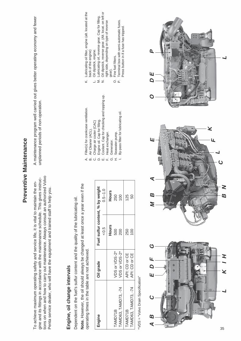
TAMD63L, -P, TAMD71B, TAMD73P, -WJ,TAMD74C, -L, -PThe engines are four-stroke, 6 cylinder in-line marinediesel engines with direct injection. They areequipped with turbochargers, charge air coolers(CACs) and heat exchangers for thermostat-control-led freshwater cooling.
The charge air cooler (CAC), which is seawater-cooled, lowers the temperature of the inlet air to theengine after compression in the turbocharger. Thispermits a high power output while keeping the com-bustion and exhaust gas temperatures to appropriatelevels.
TAMD71B: To reduce exhaust emissions when oper-ating at low load, e.g. after (cold-) starting, there is aby-pass valve which closes the air passage throughthe charge air cooler (CAC) and instead channels theair directly into the engine’s inlet manifold via theelectrical preheating element.
Introduction
This equipment is not necessary in the TAMD63,TAMD73 and TAMD74 as they have a different spec-ification, for example, higher compression, a differentcombustion chamber, and a modified injection sys-tem.
The TAMD73P (“TAMD73EDC”) and TAMD74C/L/P(“TAMD74EDC”) are equipped with an electronicallycontrolled governor, Electronic Diesel Control(“EDC”).* This further reduces exhaust emissions.
The exhaust manifold and turbocharger are fresh-water-cooled to reduce the radiant heat to the enginecompartment.
For a more detailed description of the engine, its fuel,lubrication, and cooling systems, etc., see “Techni-cal descriptions” on pages 43–70.
*Note. EDC = “Electronic Diesel Control”.
Engine design.
Serial number
Product No.
Reverse gear design.
Serial number
Product No.
Location of type plates
Type plate (decal):
Type plate:Engine designation Product No.
Serial number Basic engine No.
Decal,dataset EDC:
Certification plate: (TAMD63,TAMD73):
Approval No. (Certifying)
EMISSION APPROVED IN ACCORDANCE TO THEREQUIREMENTS OF SAV.APPROVAL NO: xxxxxxxxxx
TAMD74P-A 868821
No. xxxxxxxxxx / xxxxx
TAMD74P-ARATED POWER: 353 kW
RATED SPEED: 2600 RPM
DATASET: 873931
SPEC. NO: 868821
ECU BATCH: 9810
EN
GIN
E TAMD74P-AXXXXXXXXXX
868821
TD MG 5075A-EXXXXXXXXXX3828492
Type plate,reverse gear

9
Fig. 1. TAMD63L-A, TAMD63P-A
1. Fine fuel filters2. Smoke limiter3. Engine coolant filler cap4. Injection pump5. Oil filler cap6. Terminal box with semi-automatic fuses7. Turbocharger8. Water-cooled exhaust bend (accessory)9. Reverse gear MPM IRM 220A-1
10. TAMD63P: Wastegate valve (by-pass valve)11. Oil dipstick, engine12. Solenoid valve (fuel cut-off valve) for
stopping engine13. Oil cooler, engine14. Flexible engine mounting (accessory)
Fig. 2. TAMD63L-A, TAMD63P-A
1. Crankcase ventilation filter2. Air Cleaner (ACL)3. Charge air cooler (CAC)4. Oil filler cap5. Expansion tank6. Engine coolant filler cap7. Heat exchanger8. AC generator9. Seawater pump
10. By-pass filter for lubricating oil11. Lubricating oil filter, engine12. Starter motor13. Oil dipstick, engine14. Oil dipstick, reverse gear.
Fig. 3. TAMD71B (auxiliary engine variant)
1. Terminal box with semi-automatic fuses2. Engine coolant filler cap3. Fine fuel filters, interchangeable4. Oil filler cap5. Injection pump6. Turbocharger7. Air Cleaner (ACL)8. Oil sump9. Alt. location of oil dipstick
10. Oil cooler, engine11. Smoke limiter12. Circulation pump13. AC generator
1 2 3 4 5 6 7 8
14 13 12 11 10 9
14 13 12 11 10 9
1 2 3 4 5 6 7 8
1 2 3 4 5 6 7
13 12 11 10 9 8
10
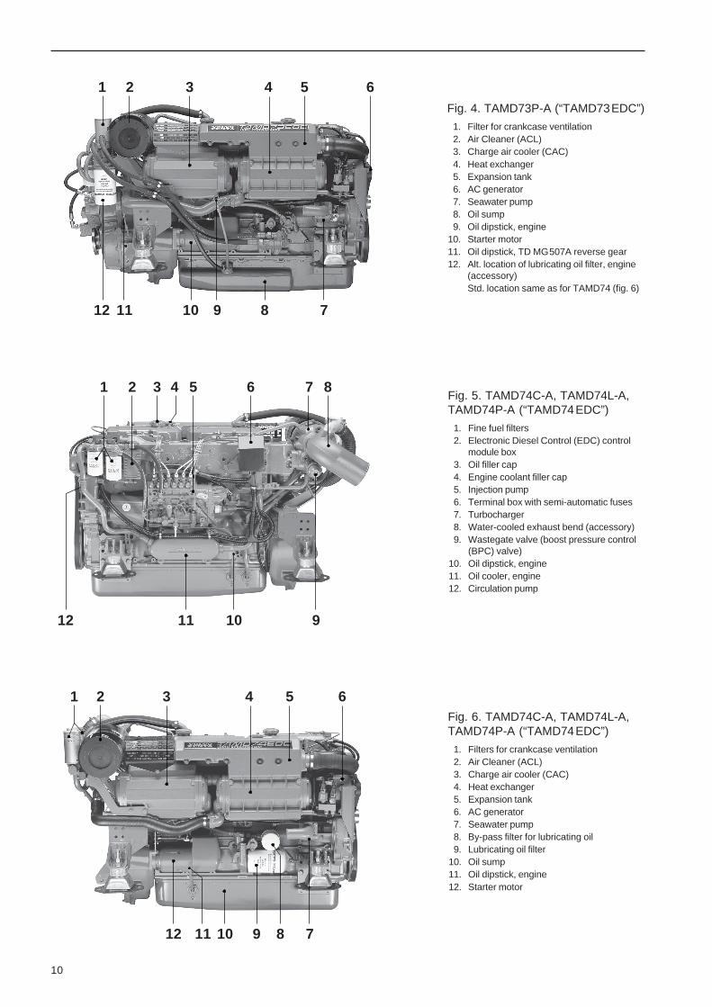
Fig. 6. TAMD74C-A, TAMD74L-A,TAMD74P-A (“TAMD74EDC”)
1. Filters for crankcase ventilation2. Air Cleaner (ACL)3. Charge air cooler (CAC)4. Heat exchanger5. Expansion tank6. AC generator7. Seawater pump8. By-pass filter for lubricating oil9. Lubricating oil filter
10. Oil sump11. Oil dipstick, engine12. Starter motor
Fig. 5. TAMD74C-A, TAMD74L-A,TAMD74P-A (“TAMD74EDC”)
1. Fine fuel filters2. Electronic Diesel Control (EDC) control
module box3. Oil filler cap4. Engine coolant filler cap5. Injection pump6. Terminal box with semi-automatic fuses7. Turbocharger8. Water-cooled exhaust bend (accessory)9. Wastegate valve (boost pressure control
(BPC) valve)10. Oil dipstick, engine11. Oil cooler, engine12. Circulation pump
12 11 10 9
1 2 3 4 5 6 7 8
12 11 10 9 8 7
1 2 3 4 5 6
12 11 10 9 8 7
1 2 3 4 5 6Fig. 4. TAMD73P-A (“TAMD73EDC”)
1. Filter for crankcase ventilation2. Air Cleaner (ACL)3. Charge air cooler (CAC)4. Heat exchanger5. Expansion tank6. AC generator7. Seawater pump8. Oil sump9. Oil dipstick, engine
10. Starter motor11. Oil dipstick, TD MG507A reverse gear12. Alt. location of lubricating oil filter, engine
(accessory)Std. location same as for TAMD74 (fig. 6)

11
InstrumentationThe instrument panels used are the main panel, the Flying Bridge (instrument panel for alt. control position), anauxiliary panel and an extra alarm panel. For the TAMD73P and TAMD74C/L/P there is also an EDC controlpanel.
The instrumentation is also supplied separately in sets if Volvo Penta instrument panels are not used. Thesesets include three smaller panels for starting, stopping and alarm functions.
Main panel1. Engine coolant temperature gauge.
2. Oil pressure gauge, engine.
3. Voltmeter. Displays start battery voltage.
4. Pressure switch for instrument lighting.
5. Key switch (start lock) with start and stop func-tions and a built-in restart inhibitor (starter motorprotection).
The start lock prevents restarting unless the keyhas first been returned to the stop position (S).
6. Alarm panel with warning symbols (positions 11–14).
7. Alarm (siren) fault detection warning. Soundswhen lubricating oil pressure is too low (engine),when coolant temperature is too high or there isa loss of charge.
8. Pressure switch for testing alarm functions or ac-knowledging alarms.
– No alarm: Alarm test (all warning lights areon and the siren sounds).
– If the alarm sounds: Alarm acknowledg-ment.*
9. Operating time meter. Displays the engine’s op-erating time in hours and tenths of an hour.
10. Tachometer, engine speed. Multiply this value by100 for revolutions per minute
* The siren stops but the warning lamps continue flashing untilthe malfunction has been corrected. If there is a new alarmthe siren sounds again at the same time as the next warninglamp starts to flash etc.
1 2 3
10 9 8 7 6 5 4
Alarm panel
This panel has four “windows”. If the acoustic alarmsounds, one of the windows “11–13” starts to flash(red) to show the cause of the alarm.
11. Warning lamp – high coolant temperature.
12. Warning lamp – low lubricating oil pressure, en-gine.
13. Warning lamp – comes on if the charging currentfrom the generator stops.
14. TAMD71B: Indication lamp – preheating on(starter element).*
*Note. Only TAMD71B has a starter element.

12
Note This lamp (14) also works as a bulb failurewarning sensor for the starter element.* The lampcomes on even when the key switch is in the I posi-tion (operating position) if there is a fault in the start-er element (break).
*Note. Only TAMD71B has a starter element.
TAMD73P and TAMD74: EDC control panel –Single engine, one or more control stations
Electronic Diesel Control (EDC) control panels(TAMD73P and TAMD74)
There are two panels for the TAMD73P and TAMD74engines for maneuvering and monitoring the func-tions of the EDC system. For single installations withone or more control points the panel has three com-bined pressbuttons and indicating lights for each con-trol position. For double installations with one ormore control points the panel has six buttons/lights.
15. “Neutral” (green). With the starter key in the op-erating position (I) the indicator light comes on(text on the button) with a steady light when thecontrol is in the neutral position.
For safety reasons the engine can only bestarted with the control in the neutral posi-tion.
Note. When used with the electronic VolvoPenta control unit there is also a function for con-trolling the engine speed with the engine disen-gaged. (This function must not be operated dur-ing starting).
Press the button in and hold it down while mov-ing the control lever to the shift position. The in-dicator light will flash when this function is en-gaged.
16. Diagnostics (yellow). The indicator lamp will startflashing if the EDC system receives abnormalsignals, or if there are technical problems withthe EDC system.
Note. If the button is pressed when the light isflashing a diagnostic readout is given to indicatewhat is causing the malfunction (the light flashesa two-digit Diagnostic Trouble Code (DTC).*
17. “Active station” (red). This button is used to up-date the EDC system on which control station isto be connected.
*For Diagnostic Trouble Codes (DTC) refer to the section:“Reading off Diagnostic Trouble Codes (DTC)” page 102.
15 16
17
NEUTRAL DIAGNOSIS
ACTIVESTATION

13
The flashing red lamp indicates that the controlstation has a fault (uncalibrated controls, a con-trol or controls not in neutral position (neutral andidle position for double controls), fault on potenti-ometer).
For information on changing the control position,refer to page 26.
18. “Sync” (blue). This button is used for engagingand disengaging the synchronization function.
For information on synchronization, refer to thereference below.
TAMD73P and TAMD74: EDC control panel for oneor more control stations (double installation)
TAMD73P and TAMD74: EDC control panel for oneor more control stations (double installation)
Synchronizing engine speed(TAMD73P and TAMD74 – twin installation)
If the boat is equipped with twin engines comfort canbe improved by synchronizing the engines to thesame engine speed. To make this process easierthere is an integral synchronization function whichautomatically sets the engines to the same enginespeed (RPM).
The synchronization function is always activatedwhen the engines are started (the light in theblue Sync button is on).
The following conditions must be met for opera-tion of the engine speed synchronization func-tion:
A. The engine speed on both engines must be morethan 800 rpm.
B. The controls for both engines must be set so thatthe difference between the two engines is notmore than 50–200 rpm when they are running at800–1000 rpm or less than 200 rpm at 1000–2500 rpm.
If these conditions are met the engine speed of thestarboard engine (the slave) will automatically be ad-justed to the speed of the port engine (master) .
If either condition A or B no longer applies thenthe synchronization function will automaticallydisengage.
Engine speed synch will also be disengaged if enginespeed exceeds 2500–2510 rpm.
Pressing the blue Sync button for at least 2 secondswill cause the Sync light to go out, and the synchroni-zation function to be disengaged after 5 seconds.Repeating this procedure will result in the synchroni-zation function being re-engaged.
16
15
16
15
17
18
ACTIVESTATION
DIAGNOSIS DIAGNOSIS
NEUTRAL SYNC NEUTRAL
SYNC

14
Extra alarm panelThis panel has four “windows”. If the acoustic alarmcomes on, one of the windows starts to flash (red) toshow the cause of the alarm.
28. Oil level too low.* Fill oil to correct level beforestarting.
29. Engine coolant level low.* Top up engine coolantto correct level before starting.
30. Water in extra fuel pre-filter. Drain off water in fil-ter. See maintenance schedule on page 38 (item12).
31. Extra alarm.
*Note. Alarms for low level with engine stopped and with starterkey in position I – (Operation position).
18
20
19
Auxiliary panel18. Oil pressure gauge for reverse gear.
19. Blank panel plugs. Space for extra switch etc.
20. Pressure gauge for turbocharger boost pressure.
Flying Bridge panel21. Tachometer, engine speed. Multiply this value by
100 for revolutions per minute
22. Operating time meter. Displays the engine’soperating time in hours and tenths of an hour.
23. Pressure switch for testing the alarm function.
24. Alarm for malfunctions, corresponding to alarmon main panel.
25. Pressure switch for instrument lighting.
26. Key switch (start lock) with start and stop func-tions and a built-in restart inhibitor (starter motorprotection).
The start lock prevents restarting unless the keyhas first been returned to the stop position (S).
27. Alarm panel with warning symbols correspondingto main panel.
21 22 23 24
27
25
26
28 29 30 31
Instrument kitsInstruments are also available as individual items inkits. There are also the following three smaller panelsfor starting and stopping the engine and using thealarm functions.

15
34
35
37
33
36
11 12 13 14
Control panel for alt. operating positionPosition numbers refer partly to the equivalent func-tions in the pilot house panel above.
Note: The key switch in the pilot house control panelmust be in position I (operating position) for startingto be carried out from the secondary operating posi-tion.
TAMD71: The starter element may be engaged onlyvia the key switch on the panel in the pilot house.
36. Starter button. The starter motor is engagedwhen this button is pressed. Release the buttonas soon as the engine has started.
37. Stop button. The stop valve (fuel cut-off valve) isengaged when this button is pressed.
Alarm panelThe alarm panel has warning symbols correspondingto those on the main panel (pos. 11–14).
Control panel for pilot house (mainpanel)32. Key switch (start lock) with start and stop func-
tions and a built-in restart inhibitor (starter motorprotection).
The start lock prevents restarting unless the keyhas first been returned to the stop position (S).
33. Pressure switch for instrument lighting.
34. Alarm (siren) fault detection warning. Soundswhen lubricating oil pressure is too low (engine),when coolant temperature is too high or there isa loss of charge.
35. Pressure switch for testing alarm functions or ac-knowledging alarms.
– No alarm: Alarm test (all warning lights areon and the siren sounds).
– If the alarm sounds: Alarm acknowledg-ment.*
* The siren stops but the warning lamps continue flashing untilthe malfunction has been corrected. If there is a new alarmthe siren sounds again at the same time as the next warninglamp starts to flash etc.
34
3533
32
16
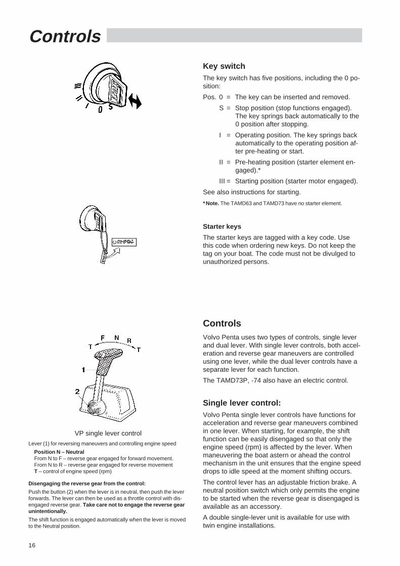
ControlsKey switchThe key switch has five positions, including the 0 po-sition:
Pos. 0 = The key can be inserted and removed.
S = Stop position (stop functions engaged).The key springs back automatically to the0 position after stopping.
I = Operating position. The key springs backautomatically to the operating position af-ter pre-heating or start.
II = Pre-heating position (starter element en-gaged).*
III = Starting position (starter motor engaged).
See also instructions for starting.
*Note. The TAMD63 and TAMD73 have no starter element.
Starter keys
The starter keys are tagged with a key code. Usethis code when ordering new keys. Do not keep thetag on your boat. The code must not be divulged tounauthorized persons.
ControlsVolvo Penta uses two types of controls, single leverand dual lever. With single lever controls, both accel-eration and reverse gear maneuvers are controlledusing one lever, while the dual lever controls have aseparate lever for each function.
The TAMD73P, -74 also have an electric control.
Single lever control:Volvo Penta single lever controls have functions foracceleration and reverse gear maneuvers combinedin one lever. When starting, for example, the shiftfunction can be easily disengaged so that only theengine speed (rpm) is affected by the lever. Whenmaneuvering the boat astern or ahead the controlmechanism in the unit ensures that the engine speeddrops to idle speed at the moment shifting occurs.
The control lever has an adjustable friction brake. Aneutral position switch which only permits the engineto be started when the reverse gear is disengaged isavailable as an accessory.
A double single-lever unit is available for use withtwin engine installations.
VP single lever control
Lever (1) for reversing maneuvers and controlling engine speed
Position N – NeutralFrom N to F – reverse gear engaged for forward movement.From N to R – reverse gear engaged for reverse movementT – control of engine speed (rpm)
Disengaging the reverse gear from the control:
Push the button (2) when the lever is in neutral, then push the leverforwards. The lever can then be used as a throttle control with dis-engaged reverse gear. Take care not to engage the reverse gearunintentionally.
The shift function is engaged automatically when the lever is movedto the Neutral position.

17
Type S controls for maneuvering trolling valve
Single lever controls with a single function are suita-ble for controlling a trolling valve*, if fitted. One ofthese is the type S control.
*The trolling valve is an accessory for the Twin Disc reversegear MG507(A)-1.
VP dual lever controls
1. Lever for reverse gear maneuvers (black handle)
Position N – NeutralFrom N to F – reverse gear engaged for forward movementFrom N to R – reverse gear engaged for reverse movement
2. Lever for controlling engine speed (rpm) (red handle)
NB dual controls
1. Lever for reverse gear maneuvers (black handle)
Position N – NeutralFrom N to F – reverse gear engaged for forward movementFrom N to R – reverse gear engaged for reverse movement
2. Lever for controlling engine speed (rpm) (red handle)
One brake can be adjusted by turning this handle in order tocounteract the regulator power
Dual lever controlThese controls have separate levers for accelerationand shifting. A mechanical lock means you can shiftonly when the acceleration lever is in the idling posi-tion. The controls have a neutral switch to preventstarting with the reverse gear engaged. Both controllevers have separately adjustable friction brakes.
Electronic controls (TAMD73P and TAMD74)
The Volvo Penta electronic, single-lever control com-bines the functions of a throttle and reverse gear op-eration in one control lever unit. When starting, forexample, the shift function can be easily disengagedso that only the engine speed (rpm)* is affected bythe lever.
The Neutral Position switch built in to the control unitonly allows the engine to be started with the reversegear disengaged.
A double single-lever unit is available for use withtwin engine installations.
*Note. The engine speed is limited to max. 2000 rpm in this po-sition.
Calibration
Before the engine is started for the first time the con-trol must be calibrated according to the instructionson the next page.
NOTE! If the calibration is not carried out the en-gine cannot be started. (Diagnostic Trouble Code(DTC) 1.6 or 1.7 will be flashed – “Control calibrationnot done”).

18
Calibrating the controls(TAMD73P and TAMD74)
NOTE! If calibration is not carried out after in-stallation, the engine cannot be started.
Calibrate first at the Master Control Station andonly then at any secondary control position(s)installed.
TAMD73P and TAMD74: Activate the requiredcontrol position by pressing the red button“Active Station” (indicator lamp comes ontogether with indicator lamp in the green Neutralbutton).
Preparations
Before the control is calibrated the EDC system mustbe put into calibration mode as follows:
1. Position control lever in Neutral position (duallever control put levers to Neutral and Idling posi-tion respectively).
2. Turn the starter key to the stop position “S” andrelease the key.
Press the yellow Diagnostics button and hold itin while turning the starter key to position “I” (op-erating position).
3. Erase stored diagnostic trouble codes (DTCs) byholding the button pressed for another 3 seconds.Note. Diagnostic trouble code (DTC) 1.6 (MasterControl Station) or 1.7 (secondary control posi-tion) cannot be erased before the control is cali-brated.
4. Turn the starter key to the stop position “S” andrelease the key.
Press the green Neutral button. Keep the buttonpressed and turn the key switch to position “I”(operating position)*. Keep the button pressed inuntil the yellow lamp goes off. Release the but-ton.
The yellow lamp starts to flash to confirm thatthe EDC system is in calibration mode.
*Note. Two persons are required for this operation, one to turnthe key switch key on the main panel while the other calibratesthe controls on a Flying Bridge position where the control pan-el does not have a key switch.
VP EDC control (electronic)
Lever (1) for reversing maneuvers and controlling engine speed
Position N – NeutralFrom N to F – reverse gear engaged for forward movementFrom N to R – reverse gear engaged for reverse movementT – control of engine speed (rpm)
Disengaging the reverse gear from the control:
Press the green button (15 see page 12) marked “Neutral” on thecontrol panel with the lever in the Neutral position. Keep the buttonpressed in and push the lever to the shift position. The lever canthen be used as a throttle with disengaged reverse gear. Take carenot to engage the reverse gear unintentionally.
The shift function is engaged automatically when the lever is movedto the Neutral position.
TAMD73P and TAMD74: EDC control panel –Single engine
NEUTRAL
Calibrating electronic single lever controlNOTE! Calibrate first at the Master Control Sta-tion followed by the other control stations(s).
1. Set the EDC system to calibration mode accord-ing to instructions in “Preparations”.
2. Move the control lever to the position where for-ward gear should start. Hold lever in this position.
Acknowledge the position by pressing in thegreen button (Neutral) for at least 3 seconds.

19
3. Move the lever to the wide open throttle (WOT)position ahead (forward) movement. Hold the le-ver in this position.
Acknowledge the position by pressing in thegreen button for at least three seconds.
4. Move the control lever to the position whereastern gear is engaged. Hold the lever in thisposition.
Acknowledge the position by pressing in thegreen button for at least three seconds.
5. Move the lever to the wide open throttle (WOT)astern position. Hold lever in this position.
Acknowledge the position by pressing in thegreen button for at least three seconds.
6. Return the lever to the Neutral position. Hold thelever in this position.
Acknowledge the position by pressing in thegreen button for at least three seconds.
7. Finish calibration by pressing down the greenbutton again (the yellow and green buttons thenstop flashing).
TAMD73P and TAMD74: EDC control panel –Single engine
TAMD73P and TAMD74: EDC control panel –Single engine
Throttle potentiometer bracket when usingmechanical control
A. Control cable movement (throw)
Calibrating mechanical single levercontrolNOTE! Certain other makes of control have beenshown to have greater travel (A) with full throttleopening with the reverse gear disengaged thanwith wide open throttle (WOT) with the reversegear engaged.
Measure the movement (A) at the potentiometerbracket at wide open throttle (WOT) and with thereverse gear engaged. Note the result.
NOTE! Calibrate first at the Master Control Sta-tion followed by the other control stations(s).
1. Set the EDC system to calibration mode accord-ing to instructions in “Preparations” (see page 18).
2. Press in the button (2) on the control unit (to dis-engage gearshift function – see illustration onpage 16). At the same time move the lever for-ward to wide open throttle (WOT) position. Holdthe lever in this position.
Acknowledge the position by pressing in thegreen button (Neutral) for at least 3 seconds.
Single lever control from other manufactur-ers: Disengage the shift function and at the sametime move the lever forward to WOT position.Hold the lever in this position.
NOTE! Check that the control cable movementdoes not exceed the value noted earlier.
Acknowledge the position by pressing in thegreen button for at least three seconds.
NEUTRAL
NEUTRAL
20
3. Move the lever to neutral position. Hold the leverin this position.
Acknowledge the position by pressing in thegreen button for at least three seconds.
4. Move the control lever to the position wherethrottle ahead (forward) movement is to start.Hold the lever in this position.
Acknowledge the position by pressing in thegreen button for at least three seconds.
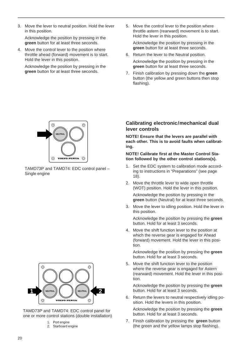
TAMD73P and TAMD74: EDC control panel forone or more control stations (double installation)
1. Port engine2. Starboard engine
NEUTRAL
1 2NEUTRAL NEUTRAL
TAMD73P and TAMD74: EDC control panel –Single engine
Calibrating electronic/mechanical duallever controlsNOTE! Ensure that the levers are parallel witheach other. This is to avoid faults when calibrat-ing.
NOTE! Calibrate first at the Master Control Sta-tion followed by the other control stations(s).
1. Set the EDC system to calibration mode accord-ing to instructions in “Preparations” (see page18).
2. Move the throttle lever to wide open throttle(WOT) position. Hold the lever in this position.
Acknowledge the position by pressing in thegreen button (Neutral) for at least three seconds.
3. Move the lever to idling position. Hold the lever inthis position.
Acknowledge the position by pressing the greenbutton. Hold for at least 3 seconds.
4. Move the shift function lever to the position atwhich the reverse gear is engaged for Ahead(forward) movement. Hold the lever in this posi-tion.
Acknowledge the position by pressing the greenbutton. Hold for at least 3 seconds.
5. Move the shift function lever to the positionwhere the reverse gear is engaged for Astern(rearward) movement. Hold the lever in this posi-tion.
Acknowledge the position by pressing the greenbutton. Hold for at least 3 seconds.
6. Return the levers to neutral respectively idling po-sition. Hold the levers in this position.
Acknowledge the position by pressing the greenbutton. Hold for at least 3 seconds.
7. Finish calibration by pressing the green button(the green and the yellow lamps stop flashing).
5. Move the control lever to the position wherethrottle astern (rearward) movement is to start.Hold the lever in this position.
Acknowledge the position by pressing in thegreen button for at least three seconds.
6. Return the lever to the Neutral position.
Acknowledge the position by pressing in thegreen button for at least three seconds.
7. Finish calibration by pressing down the greenbutton (the yellow and green buttons then stopflashing).

21
Reverse gear with electronic shiftingNote If Ahead/Astern (Forward/Reverse) on the con-trol unit do not correspond to Ahead/Astern on theboat swap the “P”/ “S” (Primary/Secondary) connec-tors between the reverse gear solenoids.
Engine idling speed (rpm) adjustment(TAMD73P and TAMD74 engines)
The engine idle speed is adjusted at the factory to600 rpm. If required the idle speed can be adjustedwithin the range 550 –700 rpm.
Note! Adjustments to engine idle speed can onlybe made from the Master control station.*
Adjust idle speed with engine at normal operat-ing temperature.**
1. Set all controls to Neutral/Idle.
2. Turn the starter key to the stop position “S” andrelease the key.
3. Press the green Neutral button on the EDC sys-tem control panel. Keep the button pressed andturn the starter key to position “I” (operating posi-tion). Keep the button pressed in (at least 3 sec-onds) until the yellow indicator lamp goes off.Release the button.
The yellow Diagnostics lamps will flash, indicat-ing that the EDC system is in calibration mode.
NOTE! With electrical shift the green lamp flash-es to confirm that gear shift function is not acti-vated. With mechanical shift the green lamp willnot flash.
4. Start the engine.*** The engine idle speed cannow be adjusted using the control lever (throttlelever) within the range 550–700 rpm (equivalentto the movement of the lever).
Mechanical single lever control: Disengagethe reverse gear function before moving the con-trol lever.
5. Set the engine idle speed required and press inthe green Neutral button on the EDC controlpanel at least 3 seconds.
6. Return the lever to the Neutral position (idle). Thegreen and yellow lamp will stop flashing. This willreengage gear shift function.
* The active control position when the power is turned on (indi-cator lamp in the green button comes on).
** At engine coolant temperatures below 15°C (59°F) the idlespeed increases to 800 rpm for a maximum of 2 minutes.
*** NOTE! The engine cannot be started until the controlunit has been calibrated. Refer to the instructions onPage 18.
TAMD73P and TAMD74: EDC control panel –Single engine
TAMD73P and TAMD74: EDC control panel forone or more control stations (double installation)
1. Port engine2. Starboard engine
MPM Twin Disc
TAMD73P and TAMD74: Cable connections tosolenoids on the reverse gear with electronicallycontrolled shifting
1 2NEUTRAL NEUTRAL
NEUTRAL

22
Before starting
Note: To reduce exhaust emissions to a minimumduring cold starts Volvo Penta recommends that aheater is installed to heat the engine room whentemperatures fall below +5°C (41°F).
1. Open the cooling water intake sea cock.
2. Check that all the drain cocks are closed and all thedrain plugs are installed.
For the positioning of cocks/plugs, see the pictureson pages 32 and 33.
3. Open the fuel cocks
4. Check that no fuel, water or oil is leaking out.
5. Check coolant level on the engine when COLD.The level must be 5 cm (2") beneath the sealingsurface of the filler cap, or between the MIN andMAX marks on the separate plastic expansion tank(accessory). For filling, see page 59.
Note. Do NOT open the pressure capwhen the engine is hot. Steam or hotcoolant can spray out and the systempressure will be lost.
6. Check the engine oil level. This should be within thearea marked on the dipstick.
The oil level must never be lower than the bot-tom mark.
7. Check the oil level in the reverse gear.*
* Note. Since the marks on the dipstick apply at operatingtemperature (with the engine idling and the control in neu-tral), the correct level before starting must be judged byexperience.
8. Switch on the main switches
9. Check the amount of fuel.
10. Push the “Alarm test” button and check that thealarm sounds (warning lamps come on). The alarmwill stop when the button is released.
Operation20
15
10
41 +5±0
–5
°F °C

23
1. Single lever control: Check that the lever is inneutral “N”. This means that the throttle control isset to idling and the reverse gear is disengaged.
Dual lever control: Move the forward/reverselever into neutral in order to start. Pull the throttlelever right back (idling position).
2. Insert the key in the key switch. Turn it to the “I”position (operating position). All warning lightswill come on. (The high coolant temperaturewarning light will go off after 20 seconds).
3. TAMD73P and TAMD74:Activate the control position to be used bypressing the red “Active Station” button.The red and green buttons (“Active Station” and“Neutral” respectively) light up to confirm thatthe control position is active.
NOTE! If the red button is flashing, the con-trol lever is not in neutral.
NOTE! For safety reasons, the control po-sition can only be activated when the con-trol lever is in the Neutral position.(The engine cannot be started until thecontrol position is activated).
4. TAMD71B:
Cold engine: Turn the key to position “II” (pre-heating). Release the key when the “starter ele-ment on” indicator lamp comes on. Activationtime is approx. 50 secs. (timer relay). Do not at-tempt to start the engine until the indicator lighthas gone out.
Hot engine: Turn the key directly to position “III”to start.
Starting the engineTo keep smoke on starting to a minimum, the TAMD71B is fitted with air preheating (a starter element). Thisstarter element is found in the inlet pipe, and its activation time is controlled by a timer relay. On the TAMD63,TAMD73 and TAMD74, which all have higher compression, different combustion chambers and a modified in-jection system, a starter element is not required.
The starter element should be on for approx. 50 s for preheating the inlet air before cold-starting. After starting,the element is switched on automatically for a further 50 s to reduce exhaust smoke during warming up and tomake the engine run evenly.
Note: On the TAMD73P and TAMD74 the electronic diesel control (EDC) system minimizes exhaust emissionsduring starting. To raise the combustion temperature before starting the starter motor turns over the engine ap-prox. 1–4 revolutions (temperature dependent) before fuel is injected.
To ensure smoother running on a cold engine the idle rpm is increased to 800 rpm for a maximum of 2 minuteswhen the engine coolant temperature is below +15°C (59°F). When the coolant temperature rises above 15°C(59°F) the idle rpm is gradually reduced to normal idle speed.
Warning! Never use start spray or similar to start the engine. There may be an explosion in the inlet man-ifold. Danger of personal injury.
ACTIVESTATION
ACTIVESTATION

24
5. Turn the key to position “III” to start* the engine(after the indicator lamp has gone out in the caseof engines with a starter element). Release thekey as soon as the engine starts.
*NOTE! The key switch has a restart inhibitor.Always start repeated start attempts from position “S”(TAMD63 and TAMD71) or position “0” (TAMD73 andTAMD74).TAMD73P: The control position must always be activatedfrom the beginning according to point 3 before a new startattempt can be made.TAMD74: If the key has been turned to position “S“, thecontrol position must be activated from the beginningaccording to point 3 before a new start attempt can bemade.
TAMD71B: After starting, the “Starter element on” in-dicator light will remain on for approx. 50 secs. (after-heating).
Warm up the engine at low speed and low load. Donot race the engine while it is cold.
When warming up the engine, check that the in-struments display normal values.
The needle on the temperature gauge should riseslowly to operating temperature, 75–95°C (167–203°F).
At operating speed, the engine’s oil pressure gaugeshould show at least approx.:
300 kPa (43 psi) – TAMD63.420 kPa (61 psi) – TAMD71, -73, -74
System voltage should be approximately 14V or 28Vdepending on whether the engine is equipped with a12V or 24V system.
The warning lights should be off* and the alarm off.
* TAMD71B: The preheating indicator light goes off approx. 50secs. after starting.
Check the oil level in the reverse gear when it hasreached operating temperature (with the engineidling and the control in neutral). The oil level shouldreach the upper mark on the dipstick.
NOTE! Never break the circuit with the mainswitches while the engine is running. Thevoltage regulator and generator may be seriouslydamaged.
TAMD63, TAMD71: The starter motor must nev-er be engaged while the engine is running*. Thestarter motor and starter gear on the flywheelmay be seriously damaged.
* Not possible on TAMD73P and TAMD74.
Checking oil level in the reverse gear
WARNING! Approaching a running engine is dangerous.Loose clothing or long hair can fasten in rotating parts andcause serious personal injury. Avoid burns. Take precau-tions to avoid hot surfaces.

25
Checks during operationCheck instruments. Normal operating values are:
Engine coolant temperature Oil pressure, engine System voltage
75–95°C TAMD63: 300–550 kPa approx. 14V (12V) or(167–203°F) TAMD71, -73, -74: 420–650 kPa 28V (24V)
If the oil pressure drops, the temperature rises above the permitted values or there is a loss of charge, thealarm will sound and one of the warning lamps will start to flash to indicate the source of the malfunction.
If the alarm sounds:
– Engine coolant temperature too high. Reduce the speed to idling (in neutral) until the temperaturedrops. Investigate the cause of the alarm (e.g. blocked engine water intake). Stop the engine if thetemperature does not drop.
– Engine oil pressure low. Stop the engine immediately and investigate the cause of the alarm.
If an extra alarm panel is fitted, the alarm will also sound if the lubricating oil or coolant levels are too low beforestarting or if there is water in the extra fuel pre-filter. An extra alarm function may also be connected.
Note! When running the engine for long periods the engine oil level must be checked at least every 8 hours withthe engine stopped (check after the engine has been stopped for approx. 3 minutes).
Reverse gear
1. Reduce engine speed to idling and, if possible,let the boat lose most of its speed.
2. Move the reverse gear control lever quickly andfirmly into the neutral position, then wait for amoment.
Maneuvering during operationFor economic running it is necessary to select an optimal cruising speed. The recommended cruising speedis the maximum speed which can be achieved at any given time minus 200 rpm.
For information on synchronization (twin engines) see page 13.
All forward/reverse maneuvering should be done at idling speed. Maneuvering at higher speeds may damagethe reverse gear and will also be uncomfortable for those on board. Maneuver as follows:
26
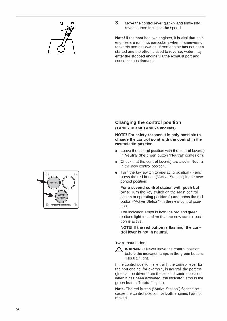
3. Move the control lever quickly and firmly intoreverse, then increase the speed.
Note! If the boat has two engines, it is vital that bothengines are running, particularly when maneuveringforwards and backwards. If one engine has not beenstarted and the other is used to reverse, water mayenter the stopped engine via the exhaust port andcause serious damage.
NEUTRAL
ACTIVESTATION
Changing the control position(TAMD73P and TAMD74 engines)
NOTE! For safety reasons it is only possible tochange the control point with the control in theNeutral/Idle position.
Leave the control position with the control lever(s)in Neutral (the green button “Neutral” comes on).
Check that the control lever(s) are also in Neutralin the new control position.
Turn the key switch to operating position (I) andpress the red button (“Active Station”) in the newcontrol position.
For a second control station with push-but-tons: Turn the key switch on the Main controlstation to operating position (I) and press the redbutton (“Active Station”) in the new control posi-tion.
The indicator lamps in both the red and greenbuttons light to confirm that the new control posi-tion is active.
NOTE! If the red button is flashing, the con-trol lever is not in neutral.
Twin installation
WARNING! Never leave the control positionbefore the indicator lamps in the green buttons“Neutral” light.
If the control position is left with the control lever forthe port engine, for example, in neutral, the port en-gine can be driven from the second control positionwhen it has been activated (the indicator lamp in thegreen button “Neutral” lights).
Note. The red button (“Active Station”) flashes be-cause the control position for both engines has notmoved.

27
Disengageable scavenging/bilge pump(accessory, TAMD71, 24V)
These pumps are engaged and disengaged via elec-tromagnetic connections and switches on the instru-ment panel. The bilge pump has a vacuum switchwhich automatically disengages it when the level isso low that no water is being sucked into the pump.The vacuum switch also has a lever for manually en-gaging the pump.
The lever must be held down for approx. 20 secondswhen engaging the pump.
Disengageable clutch (accessory, TAMD71)
The clutches have two positions on the control lever.Lever towards engine for engagement, away from itfor neutral. When engaging and disengaging theclutch, the engine speed must not exceed 800rpm.
Note. The following equipment shown can beobtained only for propulsion engines in workingboats.
Trolling valve(Twin Disc MG507-1 and MG507A-1)
If the reverse gear has a trolling valve (accessory),this should be used when the boat is to move veryslowly.
Engage the trolling valve to max. slip when the re-verse gear control is in neutral. After selecting “For-ward” or “Reverse”, the trolling valve can then be setin the required trolling position within the permittedspeed range.
The engine speed must never exceed 1100rpm when using the trolling valve.
Note! For full propeller power during operation, thetrolling valve control lever should always be in the“Disengaged” position when the valve is not in use.
Type S controls for trolling valve operation
Disengageable clutch
F = EngagedN = Neutral
Bilge pump
1. Vacuum circuit breaker2. Actuating lever

28
After operation1. Let the engine idle for a few minutes with the re-
verse gear in neutral after landing. This will evenout the engine temperature and prevent localoverheating which may cause the coolant toboil.
2. Turn the key to stop position “S”. Release thekey when the engine has stopped (key willspring back automatically into the 0 position).The key can then be taken out.
Safety precautions:
3. Close the cooling water intake sea cock and thefuel cocks. For anti-freeze protection, see sec-tion “Precautions against freezing” on page 32.
4. Switch off the main switches if the boat is not tobe used for some time.
5. Inspect the engine and engine compartment forany leaks.
Emergency stop
Pull the stop lever on the governor to the rear formanual stop (emergency stop).

29
DIAGNOSIS
ACTIVESTATION
Safety systems (TAMD73P and TAMD74)
Emergency operation of the engine
IMPORTANT!
The engines are equipped with an emergency op-eration function (“Limp-home”). The function en-gages automatically and makes it possible tocontinue running the engine and reach harbour ifcommunication between the control and the en-gine is broken.
When the Limp-home function is connected:
The red lamp (“Active Station”) and the yellowlamp (“Diagnosis”) flash in the control panel(EDC).
WARNING! The control(s) for the affect-ed engine do not function.
The engine speed is set to 1000 rpm and the re-verse gear is set in Neutral for safety.
Contact an authorised workshop for correctiveaction as soon as possible.
If movement ahead (forward) is required –proceed as follows:
1. Stop the engine.
2. Engage reverse gear manually for Ahead move-ment. See the next section “Reverse gear emer-gency operation”.
3. Start the engine (propulsion engages immediate-ly).
WARNING! In order to interrupt pro-pulsion the engine must be stoppedusing the key switch or stop button, ifapplicable.
The control(s) for the affected enginedo not function.

30
Twin Disc MG5075 – Engagement
1. Stop engine and remove the key from the keyswitch.
2. Note to which solenoid valve (P or S) the wiringmarked “Primary” is connected. Detach the con-nector from both solenoids.
3. Remove the covering nut on top of the solenoidvalve where the “Primary” cable was installed.
4. Press in button (A) on the solenoid and turn thebutton half a turn clockwise until the catch point.
WARNING! After engagement the reversegear is locked for use Ahead and cannotbe disengaged with the control.
Twin Disc MG5075: Manual engagementof reverse gear (safety system)
A. Pushbutton
P. Solenoid switch (Primary). Used normally for Ahead (forward)movement
S. Solenoid valve (Secondary). Used normally for Astern (back-ward) movement
Reverse gear emergency operationOn MPM and Twin Disc reverse gears with electroni-cally operated shifting there is a safety feature formanual engagement of Ahead (forward movement)should a malfunction occur on the reverse gear sole-noid valve.
MPM – Engagement
1. Stop engine and remove the key from the keyswitch.
2. Note to which solenoid valve (P or S) the wiringmarked “Primary” is connected. Detach the con-nector from both solenoids.
3. Press in button (A) on the solenoid where the“Primary” cable was installed. Turn button half aturn counter-clockwise to locked position.
WARNING! After engagement the reversegear is locked for use Ahead and cannotbe disengaged with the control.
MPM: Manual engagement of reverse gear(safety system)
A. Pushbutton
P. Solenoid switch (Primary). Used normally for Ahead (forward)movement
S. Solenoid valve (Secondary). Used normally for Astern (back-ward) movement

31
Propeller shaft brakeUnder certain operating conditions, the propeller maymake the propeller shaft rotate when the engine isstopped. This rotation may damage the reverse gearsince its oil pump, which is driven by the integralshaft, stops when the engine stops.
The propeller shaft can be permitted to rotate withthe engine stopped for up to 6–8 hours. After thistime the engine must be started for at least 5 min-utes to ensure the reverse gear is lubricated andcooled.
If the shaft is likely to rotate more quickly than duringnormal operation, e.g. during sailing, a temperaturegauge should be fitted which monitors the tempera-ture of the oil.
The max. permitted temperatures are 110°C (230°F)for Twin Disc and 95°C (203°F) for MPM reversegears.
If the above conditions cannot be met a brake mustbe installed. A temporary solution is to lock the pro-peller carrier mechanically instead.
Other Twin Disc – Engagement
1. Stop engine and remove the key from the keyswitch.
2. Note to which solenoid valve (P or S) the wiringmarked “Primary” is connected. Detach the con-nector from both solenoids.
3. Remove the solenoid and the valve body (V) onthe valve where the “Primary” cable was in-stalled.
4. Unscrew plug (A) from its holder on the reversegear. Install the plug in the valve body hole as il-lustrated.
Tightening torque: Max. 27 Nm (2.7 kpm = 19.9lbf.ft).
WARNING! After engagement the reversegear is locked for use Ahead and cannotbe disengaged with the control.
Other Twin Disc: Manual engagement ofreverse gear (safety system)
A. Plug*
P. Solenoid valve (Primary). Used normally for Ahead (forward)movement
S. Solenoid valve (Secondary). Used normally for Astern (back-ward) movement
V. Valve body
* Tightening torque: Max. 27 Nm (2.7 kpm = 19.9 lbf.ft).
Back-up power supply
If the battery voltage should for any reason drop be-low normal during operation (generator not chargingor discharged batteries) the engine will stop.
A back-up system is required to start the engine. Onpages 79, 81, 85 and 87 can be found a suggestionfor installing a back-up starting system for 12V and24V respectively.
The back-up system is activated by switching in us-ing the main switch (“2B” in the wiring diagram) whichbrings the emergency/extra batteries on line with thestarter batteries.
NOTE! The back-up system batteries must be in acharging circuit from the generator on the engine, forexample, although this is not included in the enginewiring diagrams.
Note. This system is not factory installed from VolvoPenta, it must be installed during the engine installa-tion.
Check in the Instruction Book for the boat if thereis some other type of back-up system supplied.
NOTE! If there is a short-circuit in the electrical sys-tem, one or more of the semi-automatic fuses will tripand the engine will stop.* The fault must be correctedbefore the engine can be re-started.
*Note. Refer to page 69 for resetting the fuses.

32
Precautions against freezingCheck the antifreeze in the freshwater system after the engine has stopped if there is a risk of freezing. Seeunder the heading. “Coolant” on page 94.
Drain the water from the seawater system as described below. Check that all the water has drained out.
Check batteries in accordance with instructions on page 72. A poorly charged battery can burst if it freezes.
Draining coolantBefore draining the coolant, the engine should be stopped, the filler cap unscrewed and the boat’s seacock closed. Then open the drain cocks or remove the drain plugs of the engine’s freshwater and seawatersystems. See the illustrations below and on the next page.
Check that all the water runs out. There may be deposits by the cock/plug which must be removed. Otherwisethere is a risk that water may remain in the system and cause serious damage.
Check whether the installation has any more cocks or plugs on the cooling water and exhaust pipes’ lowestpoints.
NOTE! To protect the environment please dispose of used coolant at a properly designated dis-posal site.
Remove the cover from the seawater pump and the cover on any extra pump.
Close the cocks, fit the plugs and put the cover on the seawater pump (and any extra pump fitted). Pump outthe boat if required. Ensure that there are no leaks before you leave the boat.
See the instructions on page 59 for topping up the coolant.
TAMD71
F = Freshwater cocks/plugs S = Seawater cocks/plugs V = Venting cock

33
F
TAMD63
S S S F S
S S S F S S
TAMD73, TAMD74 F V
F F
TAMD63, TAMD73, TAMD74
Note: Remove the cover on the seawater pump. Also remove the hose between the heat exchanger and thereverse gear’s oil cooler, then drain off the water while draining the seawater system.
F = Freshwater cocks/plugs S = Seawater cocks/plugs V = Venting cocks
TAMD63 F V
F F
F
TAMD73, V VTAMD74

34
Maintenance and carePeriodic maintenanceIf your engine and its fittings are to function reliably, periodic maintenance in accordance with the maintenanceschedule is required. Several of the points below cover the replacement of consumables such as oil and fuel fil-ters etc.
To ensure continued trouble-free use of your engine, it is important always to use original spares. Always statethe type designation and serial number of your engine and its fittings when ordering parts.
Some operations require professional experience and special tools. Therefore, get authorized service personnelto carry out more extensive work.
For further information, see under the heading “Maintenance” in accordance with the respective section in“Technical Description”.
New engine with reverse gearSee instructions. “Running-in” on page 4.
Layout of the maintenance schedule
Shading denotes simpleroperations which can becarried out by the boat own-er personally.
Lines indicate operationswhich require experienceand/or special tools. Thiswork should therefore beleft to authorized servicepersonnel.
Under the heading “In-struction ” is a brief sum-mary of what should be rec-tified when carrying out themaintenance job in ques-
tion.
Under the heading “Info.page” are references to theinformation pages at theback of this book. In mostcases, these pages providea more detailed description
1. Changing the Engine oil.Note. Refer to table on page 35 for informa-tion on oil grade/intervals between changes
1) For TAMD63, TAMD73 and TAMD74.2) For TAMD71 engines.
2. Replace oil filter (1) andby-pass filter if fitted (2)at every other oilch arings, disengaging
inspection cover. Release the catcg (B) counterclockwise (Rockford/BW), or clockwi
he catch. The clutch plates must not slip after engagement.
Engine oil VDS or CD or CE as per API system. Drain or pump out oil whileengine is hot.
Warning! Hot oil can cause burns.
Lubricate gasket and screw on new filter by hand. Tighten by 3/4 turn oncegasket is tight. Top up oil, start, check for leaks. Stop engine and ch
p with oil. Quality: Userefer to Te
. Check/adjust disengage-able clutch (if fitted).
11. Replace filter(s) forcrankcase ventilation.
TAMD63, TA TAMD71B
* Note. Special recommendations apply for new or reconditionedengines. See instructions. “Running-in” on page 4.
49
49
–
45
123456789012345678901234567890121231234567890123456789012345678901212312345678901234567890123456789012123
Screw on new filter by hand. Note: Replace filter earlier if air and oil mixturebegins to come out of the valve (1).TAMD71: Check the drain hose (2) is not clogged.
12341234123412341234123412341234123412341234
1) 2)
Rockford/BW A. P.
50 H
rs
100
Hrs
250
Hrs
500
Hrs
1000
Hrs
2000
HrsNo. Operation Instructions Info.
pge.
Eng
ine,
oil
chan
ge in
terv
als
Dep
ende
nt o
n th
e fu
el’s
sul
fur
cont
ent a
nd th
e qu
ality
of t
he lu
bric
atin
g oi
l.
Not
e. H
owev
er, t
he o
il sh
ould
alw
ays
be c
hang
ed a
t lea
st o
nce
a ye
ar e
ven
if th
eop
erat
ing
times
in th
e ta
ble
are
not a
chie
ved.
Eng
ine
Oil
grad
eF
uel s
ulfu
r co
nten
t, %
by
wei
ght
<0.
50.
5–1
.0
Hou
rsH
ours
TA
MD
71B
VD
S o
r V
DS
-2*
500
250
TA
MD
63, T
AM
D73
, -74
VD
S o
r V
DS
-2*
200
100
TA
MD
71B
AP
I: C
D o
r C
E25
012
5T
AM
D63
, TA
MD
73, -
74A
PI:
CD
or
CE
100
50
*VD
S =
“V
olvo
Dra
in S
peci
ficat
ion”
Pre
vent
ive
Mai
nten
ance
To
achi
eve
max
imum
ope
ratin
g sa
fety
and
ser
vice
life
, it i
s vi
tal t
o m
aint
ain
the
en-
gine
and
its
fittin
gs in
acc
orda
nce
with
the
mai
nten
ance
sch
edul
e. T
his
give
s in
stru
c-tio
ns o
n w
hen
and
how
to c
arry
out
mai
nten
ance
. Alw
ays
cons
ult a
n au
thor
ized
Vol
voP
enta
ser
vice
dea
ler,
who
will
hav
e th
e eq
uipm
ent a
nd tr
aine
d st
aff t
o he
lp y
ou.
A m
aint
enan
ce p
rogr
am w
ell c
arrie
d ou
t giv
es b
ette
r op
erat
ing
econ
omy
and
few
erun
plan
ned
perio
ds o
f no
n-op
erat
ion.
A.
Filt
er(s
) fo
r cr
ankc
ase
vent
ilatio
n.B
.A
ir C
lean
er (
AC
L).
C.
Cha
rge
air
cool
er (
CA
C)
D.
Eng
ine
oil.
Cap
for
fillin
g.E
.C
oola
nt. C
ap fo
r ch
ecki
ng a
nd to
ppin
g up
.F
.H
eat e
xcha
nger
.G
.G
ener
ator
.H
.S
eaw
ater
pum
p. I.
By-
pass
filte
r fo
r lu
bric
atin
g oi
l.
K.
Lubr
icat
ing
oil f
ilter
, eng
ine
(alt.
loca
ted
at th
eba
ck o
f the
eng
ine)
L.O
il di
pstic
k, e
ngin
e.M
.Lu
bric
atin
g oi
l, re
vers
e ge
ar. C
ap fo
r fil
ling.
N.
Oil
dips
tick,
rev
erse
gea
r. (
Alt.
loca
t. on
left
orrig
ht s
ide,
dep
endi
ng o
n ty
pe o
f rev
erse
gear
).O
.F
ine
fuel
filte
rs.
P.
Ter
min
al b
ox w
ith s
emi-a
utom
atic
fuse
s.P
ress
but
ton
in if
a fu
se h
as tr
ippe
d.
OD
EP
L
MB
AE
BN
KL
FC
AB
CE
DF
G
LK
IH
35

1) 2)
*
3) 4)
* *
Maintenance scheduleThe description applies generally for all engines unless otherwise stated.
If longer intervals are required than those stated below the oil’s condition must be testedregularly by the oil manufacturer.
The time intervals are guides which apply to normal operating conditions. For new orreconditioned engines see under the heading. “Running-in” on page 4.
All operations below with the exception of points 17, 21 and 32 must be carried out at leastonce per year even if the operating time in the schedule has not been reached. Operations17, 21 and 32 must be carried out at least once every other year.
NOTE! Always turn the engine off before starting service procedures (except opera-tion 16)!
1. Changing the Engine oil.Note. Refer to table on page 35 for infor-mation on oil grade/intervals betweenchanges.
1) For TAMD63, TAMD73 and TAMD74.2) For TAMD71 engines.
2. Replace oil filter (1) andby-pass filter if fitted (2)at every other oil change.
3. Change oil in reversegear.3) MPM (ZF).4) Twin Disc.
4. MPM reverse gear:Remove and clean re-verse gear oil screen.
5. Replace oil filter on MPMIRM 301A and 302V re-verse gears.
* Note. Special recommendations apply for new or reconditioned
engines. See instructions “Running-in” on page 4.
49
49
50
50
–
Engine oil VDS or CD or CE as per API system. Drain or pump out oil while engineis hot.
Warning! Hot oil can cause burns.
Remove plug and oil screen. Clean screen and reinstall components removed.Start engine (after filling with oil) and check for leaks.
Lubricate gasket and screw on new filter by hand. Tighten by 3/4 turn once gasketis tight. Top up with oil. Start engine, check for leaks. Check oil level (point 3above).
50 H
rs
100
Hrs
250
Hrs
500
Hrs
1000
Hrs
2000
HrsNo. Operation Instructions Info.
pge.
TAMD63, TAMD73, TAMD74 TAMD71
Lubricate gasket and screw on new filter by hand. Tighten by 3/4 turn oncegasket is tight. Top up oil, start, check for leaks. Stop engine and check oillevel.
Fill up with oil. Quality: Use CD, CE or CC engine oil, but not multigrade oil . Forviscosity refer to Technical Data. Check the oil level. Note: The markings on thedipstick refer to levels at operating temperature (with the engine idling and thecontrol in neutral).

123456789012345678901
123456789012345678901
123456789012345678901
123456789012345678901
123456789012345678901
*
*
*
6. Twin Disc reverse gear:Remove and clean re-verse gear oil screen.
7. Replace oil filter in re-verse gear Twin DiscMG507(A)-1 with trollingvalve and MG5085.
8. Lubricate release bear-ing on disengageableclutch (if fitted).
9. Lubricate disengageableclutch (if fitted).
10. Check/adjust disengage-able clutch (if fitted).
11. Replace filter(s) forcrankcase ventilation.
* Note. Special recommendations apply for new or reconditioned
engines. See instructions “Running-in” on page 4.
50
–
–
–
–
45
Remove plug and oil screen. Clean screen and reinstall components removed.Start engine (after filling with oil) and check for leaks.
Rockford /BW A. P.
Remove clamp (1). Remove cover and take out filter. Clean filter holder and installnew filter. Check oil level (point 3 above).
Note. Every 50 hours, applies when clutch operations per day exceed 15–20 op-erations. Otherwise every 500 hours. Use grease sparingly so that it is notpressed out. Use lithium-based lubricating grease: Mobilux EP2, Statoil UniwayEP2N, Texaco Multifak EP2, Q8 Rembrandt EP2.
Lubricate inner support bearing (when a grease nipple is fitted), main bearings,disengaging shaft and moving parts of clutch. Lubricate sparingly (20–30 g formain bearings). Quality: see point 8 above. A few drops of oil on inner link arms.
WARNING! Engine must be stopped when adjustment is carried out.Remove the inspection cover. Release the catch (A) and turn the adjuster ring (B)counterclockwise (Rockford/BW), or clockwise (A.P.). Engage the catch. Theclutch plates must not slip after engagement.
Screw on new filter(s) by hand. Note: Replace filter(s) earlier if air and oil mixturebegins to come out of the valve (1).TAMD71: Check the drain hose (2) is not clogged.
50 H
rs
250
Hrs
500
Hrs
1000
Hrs
2000
Hrs
12 m
onth
s
No. Operation Instructions Info.pge.

123456789012345678901
123456789012345678901
123456789012345678901
123456789012345678901
123456789012345678901
12. Check/drain extra fuelfilter.
13. Replace insert(s) in extracoarse fuel filter.
14. Replace fine fuel filters.
15. Vent fuel system.
16. Replace adjustable fuelfilters.(For TAMD71 auxiliary engine)
17. Have authorized servicepersonnel check injec-tors.
A few hours after stopping engine: Drain off water or contaminants through cock/plug (1). 53
53
54
54
54
55
Close the fuel cocks at the tank before dismantling the single filter or replacingthe inserts of the double filter with the engine off. See also instructions on page53.
Screw on new filters by hand. Tighten by 1/2 turn once gasket is tight. Cleanli-ness! The fuel in the system must not become contaminated. Vent system – seepoint 15 below.
Open vent screw (1). Pump with hand pump (2) until fuel containing no air flowsout. Close screw while fuel is flowing out. Then pump a further 10–20 times.Check for leaks.
Lever (2) on right – replace left filter. Lever up – vent left filter. Venting nipple (1).Replace the right side filter in the same way. For filter installation refer to point 14above.
Hand in injectors to authorized service dealer (or replace with adjusted injectors).Tightening torques: Injectors 50 Nm (5 kpm/37 lbf.ft.), pressure pipes 15–25 Nm,(1.5–2.5 kpm/11.1–18.5 lbf.ft.). NOTE! Pressure pipes on TAMD63, TAMD73and TAMD74 must NOT be bent. Replace damaged pressure pipes.
50 H
rs
250
Hrs
500
Hrs
1000
Hrs
2000
Hrs
12 m
onth
s
No. Operation Instructions Info.pge.
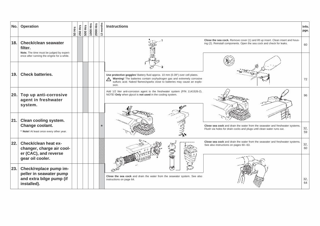
18. Check/clean seawaterfilter.Note. The time must be judged by experi-ence after running the engine for a while.
19. Check batteries.
20. Top up anti-corrosiveagent in freshwatersystem.
21. Clean cooling system.Change coolant.* Note! At least once every other year.
22. Check/clean heat ex-changer, charge air cool-er (CAC), and reversegear oil cooler.
23. Check/replace pump im-peller in seawater pumpand extra bilge pump (ifinstalled).
123456789012345678901
123456789012345678901
123456789012345678901
123456789012345678901
123456789012345678901
50 H
rs
250
Hrs
500
Hrs
1000
Hrs
2000
Hrs
12 m
onth
s
Close the sea cock. Remove cover (1) and lift up insert. Clean insert and hous-ing (2). Reinstall components. Open the sea cock and check for leaks. 60
72
96
32,59
32,60
32,64
Use protective goggles ! Battery fluid approx. 10 mm (0.39") over cell plates.Warning! The batteries contain oxyhydrogen gas and extremely corrosivesulfuric acid. Naked flames/sparks close to batteries may cause an explo-sion.
Add 1/2 liter anti-corrosion agent to the freshwater system (P/N 1141526-2).NOTE! Only when glycol is not used in the cooling system.
Close sea cock and drain the water from the seawater and freshwater systems.Flush via holes for drain cocks and plugs until clean water runs out.
Close sea cock and drain the water from the seawater and freshwater systems.See also instructions on pages 60–63.
Close the sea cock and drain the water from the seawater system. See alsoinstructions on page 64.
No. Operation Instructions Info.pge.
*

24. Inspect/replace zincanode(s)
25. Check for oil, fuel orwater leaks.
26. Check the batteries’charge condition.
27. Check/tension drivebelt(s).
28. Check electrical connec-tions.
29. TAMD63: Clean aircleaner (ACL).
50 H
rs
250
Hrs
500
Hrs
1000
Hrs
2000
Hrs
12 m
onth
s
32,63
–
72
45
72
–
Close sea cock before starting work. Drain the water from the seawater sys-tem. Replace the anode if more than 50% of it has been used. When fitting, en-sure that there is good metallic contact between the anode and the material.
Check all connections and check for leaks. The rubber hoses should not becracked or damaged, and all hose clips and connections should be tightenedproperly.
Check the batteries’ charge condition using a hydrometer. At an ambient tempera-ture of approx. +25°C (77°F) the battery electrolyte density should be 1.28 g/cm3
(1.24 g/cm3 with tropical acid). Charge the batteries if the density has dropped by0.04 g/cm3.
Wash the insert in clean diesel. Squeeze it out and place it in the filter housing. Fixthe insert by pushing the O-ring down into the groove around the outer edge of theinsert.NOTE! Replace the filter insert if it is damaged.
No. Operation Instructions Info.pge.
TAMD63, TAMD73, -74 TAMD71
Check for wear. Belts which work in pairs should be replaced at the same time.Undo screws (A) before tensioning the belt(s).TAMD63, -73, -74: Tension belt to 60 ±3 Nm (6 ±0.3 kpm/44 ±2 lbf.ft.).TAMD71: It should be possible to depress the belts 10 mm (0.4") between thepulleys.
Clean the batteries’ terminal posts and cable clips, lubricate them with Vaselineand tighten them. Also check that all other connections are properly tightened andhave good contact. If necessary, spray these connections with a moisture-repel-lent spray.

1234567890123456789012345678901212345678901234567890123456789
1234567890123456789012345678901212345678901234567890123456789
1234567890123456789012345678901212345678901234567890123456789
1234567890123456789012345678901212345678901234567890123456789
1234567890123456789012345678901212345678901234567890123456789
50 H
rs
250
Hrs
500
Hrs
1000
Hrs
2000
Hrs
12 m
onth
s
30. TAMD71: Replace aircleaner (ACL) filter in-serts.
31. TAMD73, TAMD74:Replace air cleaner(ACL).
32. Have authorized person-nel check valve clear-ance.
33. TAMD63, TAMD73, -74:Get authorized person-nel to check turbo charg-ing pressure.
34. TAMD63P, TAMD73P, -74P: Get authorized per-sonnel to check functionof wastegate valve.
35. Get authorized person-nel to carry out a generalcheck of engine and fit-tings.
* Note. Special recommendations apply for new or reconditioned
engines. See instructions “Running-in” on page 4.
–
–
46
–
–
–
Undo the clamps (x 6) for the covers (1). Remove the covers and replace the filterinserts. Check that the rubber hose against the turbocharger is undamaged andthat the new filters are scrupulously clean. Reinstall components.
Lift out and remove the filter for disposal. Take care that no contaminants enterthe engine. Install new air cleaner (ACL) – (TAMD73WJ: together with rubber ring“A”) and tighten the hose clamps.
Get authorized service personnel to check/adjust the valve clearance. This shouldbe done with the engine off , cold or at operating temperature!
Get authorized service personnel to check the turbocharger’s charging pressure.
Get authorized service personnel to check the function of the wastegate valve.
Get authorized service personnel to check the condition of the turbocharger andcarry out a general check of the engine and its fittings.
123456789012345678901
123456789012345678901
123456789012345678901
123456789012345678901
123456789012345678901
*
No. Operation Instructions Info.pge.

123456789012345678901
123456789012345678901
123456789012345678901
123456789012345678901
123456789012345678901
36. TAMD73P and TAMD74:Check the EDC system.
37. Check surface finish ofengine and reverse gear.
No. Operation Instructions Info.pge.
50 H
rs
250
Hrs
500
Hrs
1000
Hrs
2000
Hrs
12 m
onth
s
Have authorized service personnel check the EDC system using a diagnostictool.
Improve external corrosion protection by painting over any abraded parts withoriginal paint.
WARNING! Never use high-pressure jets when washing the engine. Neverpoint the water jet at seals, rubber hoses or electrical components.
–
–

43
Technical descriptionEngineThese engines are four-stroke, straight six marine diesel engines with overhead valves. They are fluid-cooledand equipped with turbochargers. The inlet air to the engine is cooled by a seawater-cooled charge air cooler(CAC) after compression in the turbo.
The engines have piston cooling (oil-cooled pistons). The lubrication system has a full flow oil filter, and theTAMD63, TAMD73 and TAMD74 engines also have a partial flow (by-pass) filter. This by-pass filter is anaccessory on the TAMD71 engines.
The cooling system is divided into a freshwater and a seawater system. The seawater cools the freshwatersystem via a heat exchanger (TAMD71 has double heat exchangers).
Cylinder headsThe engines have two cylinder heads, each of whichcovers three cylinders. A special alloy cast ironmaterial is used for the cylinder heads. The cylinderhead gaskets are made of solid sheet steel and havespecial rubber sealing rings inside for oil and coolantchannels.
The journal at the front of the crankshaft has beenground to a polygonal shape. A polygon joint canwithstand the stresses from the vibration damper(extra pulley or disengageable clutch) considerablybetter than a keyed joint.
Piston cooling
Valve systemThe camshaft is journalled in seven bearings and isdriven by the timing gears. The camshaft actuatesthe inlet and outlet valves in the cylinder heads vialifters, push rods and rockers.
In the TAMD71, TAMD73 and TAMD74, these valveshave double valve springs.
Cylinder blockThe cylinder block is made of special alloy cast ironand cast in one piece. The cylinder liners are of thewet type and are replaceable. The liners have aflame guard bevel which considerably increases theservice life of the cylinder head gaskets.
CrankshaftThe heavy-duty crankshaft is extremely strong and isjournalled in seven main bearings. This shaft isstatically and dynamically balanced and temperedaccording to a special method (nitrocarburization).This increases the fatigue strength and gives thebearing journals an extremely hard surface.
PistonsThe pistons, which are made of an aluminum alloy,have two compression rings and one oil ring. Thecompression rings are coated (upper compressionring in the TAMD63), which helps reduce oil con-sumption and the risk of ring seizing.
To reduce carbonization at high engine loads thepistons are oil cooled. Piston cooling increases theservice life of pistons, piston rings and cylinder linersand reduces oil consumption.
The engine’s combustion chambers are entirelyconfined to the piston crowns.
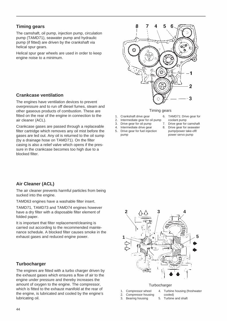
44
Timing gearsThe camshaft, oil pump, injection pump, circulationpump (TAMD71), seawater pump and hydraulicpump (if fitted) are driven by the crankshaft viahelical spur gears.
Helical spur gear wheels are used in order to keepengine noise to a minimum.
Turbocharger
1. Compressor wheel 4. Turbine housing (freshwater2. Compressor housing cooled)3. Bearing housing 5. Turbine and shaft
Timing gears
1. Crankshaft drive gear 6. TAMD71: Drive gear for2. Intermediate gear for oil pump coolant pump3. Drive gear for oil pump 7. Drive gear for camshaft4. Intermediate drive gear 8. Drive gear for seawater5. Drive gear for fuel injection pump/power take-off/
pump power servo pump
Crankcase ventilationThe engines have ventilation devices to preventoverpressure and to run off diesel fumes, steam andother gaseous products of combustion. These arefitted on the rear of the engine in connection to theair cleaner (ACL).
Crankcase gases are passed through a replaceablefilter cartridge which removes any oil mist before thegases are led out. Any oil is returned to the oil sump(by a drainage hose on TAMD71). On the filtercasing is also a relief valve which opens if the pres-sure in the crankcase becomes too high due to ablocked filter.
Air Cleaner (ACL)The air cleaner prevents harmful particles from beingsucked into the engine.
TAMD63 engines have a washable filter insert.
TAMD71, TAMD73 and TAMD74 engines howeverhave a dry filter with a disposable filter element offolded paper.
It is important that filter replacement/cleaning iscarried out according to the recommended mainte-nance schedule. A blocked filter causes smoke in theexhaust gases and reduced engine power.
TurbochargerThe engines are fitted with a turbo charger driven bythe exhaust gases which ensures a flow of air to theengine under pressure and thereby increases theamount of oxygen to the engine. The compressor,which is fitted to the exhaust manifold at the rear ofthe engine, is lubricated and cooled by the engine’slubricating oil.
2 3 4
1 5

45
TAMD63P, TAMD73P and TAMD74 also have awastegate valve (boost pressure control (by-pass)valve) installed in the turbine housing.
The wastegate valve means that the turbocharger isoptimized for high charging pressure even at lowengine speeds. The engine’s low-speed torque isthereby improved greatly, while it also reacts morequickly to load changes.
At higher engine loads, the wastegate valve opensand forces some of the exhaust gases past the turboand directly out into the exhaust pipe.
The turbocharger is freshwater cooled to reducedradiant heat in the engine room.
TAMD63P, TAMD73P and TAMD74: Basicdiagram of turbocharger with wastegate valve
1. Air from air filter 6. Exhaust gas flow past turbine2. Compressed air to engine via wastegate valve at high3. Compressor housing engine loads4. Turbine housing 7. Exhaust gases from engine5. Exhaust gases outlet
Maintenance – Engine
Replacing crankcase ventilation filter(s)1. Remove the old filter by unscrewing it counter-
clockwise. Note! TAMD73 and TAMD74 havetwo filters.
2. Check the rubber gasket in the mounting, replaceif necessary. Screw on the new filter by hand.
3. TAMD71: Check the drain hose is not clogged.
Checking/tensioning drive belt(s)Check the belt(s) for wear. Replace belt(s) whennecessary. Belts which work in pairs should bereplaced at the same time.
Undo screws (A) before tensioning the belt(s).
TAMD63, TAMD73 and TAMD74: Place the stud ofa torque wrench in the square hole in the tensioningpulley bracket. Tension belt to 60 ±3 Nm (6 ±0.3kpm/44 ±2 lbf.ft.).
Tighten screws (A).
TAMD63, TAMD73, TAMD74: Tensioning drive belt
A. Locking screws
Charge air cooler (CAC)The inlet air passes through the charge air cooler(s)after compression in the turbocharger. The chargeair cooler lowers the temperature of the air andthereby considerably improves the output ratio as thevolume of the air is reduced. More air (oxygen) cantherefore be forced into the engine’s cylinders andburn more fuel per compression stroke; thus increas-ing output. Charge air cooling also helps reduce thethermal load on the engine.
See also under the heading “Heat exchanger andcharge air cooler” on page 58.
TAMD73, TAMD74: Crankcase ventilation filters
1. Filter 2. Relief valve

46
TAMD71: Tensioning drive belts
A. Locking screws
TAMD71: It should be possible to depress the belts10 mm (0.4") between the pulleys at the correcttension.
Tighten screws (A).
Valve location
Intake Exhaust
Checking the Turbocharger (TC)This check should be left to authorized servicepersonnel.
However, a quick check of the turbocharger whencleaning/replacing the air cleaner may be carried outas follows:
1. Remove air cleaner (ACL).
2. Warning! Check that the turbocharger’simpeller is stationary before checking.
3. Check if the shaft is stiff or if the turbine orcompressor wheels are touching their housings.Turn the shaft using light pressure, followed bypulling it gently in the axial plane.
If the rotor is difficult to turn, the turbochargermust be replaced or reconditioned as soon aspossible.
Note. If the turbocharger unit is to function satisfacto-rily, it is vital that the engine’s lubrication system bemaintained according to the maintenance scheduleand that the correct type of lubricating oil be used inthe engine.
Checking valve clearanceThis check should be left to authorized servicepersonnel.
Note! The clearance must never be checked withthe engine running – the engine must be stopped– cold or at operating temperature.

47
Technical descriptionLubrication systemThese engines have a forced lubrication system and piston cooling (see “Pistons” on page 43). The oil pump isof the gear-wheel type and is located at the front of the oil sump. This pump is driven by the engine’s timinggears.
The oil pump sucks oil up from the oil sump and then forces it out into two main channels in the cylinder block(see basic diagram on next page). The oil passes through the lubricating oil filter and then on into the engine’soil channels for the forced lubrication of the engine, injection pump and turbocharger. The oil also passesthrough via the piston cooling valve. From here a small amount of oil is channelled off, which then passesthrough a by-pass filter (in the TAMD63, TAMD73 and TAMD74 – accessory in the TAMD71) before beingreturned to the oil sump. The rest of the oil continues through the oil cooler and out to the piston cooling jets.
Lubrication TAMD71
1. Main oil channel (lubricating oil) 15. Filtered oil (pressure) to lubri-2. Pressure line to turbocharger cation system3. Main oil channel (piston-cooling oil) 16. Oil (pressure) from oil pump4. Rocker mechanism 17. Return oil to oil sump via relief5. Oil channel to rocker mechanism valve6. Main bearings. 18. Oil (pressure) via piston cool-7. Big-end bearings ing valve to oil cooler and piston8. Oil pump cooling9. Oil to oil cooler and piston cooling 19. Return oil to oil sump (via by-
10. Lubricating oil filter (full flow type) pass filter, if fitted)11. Camshaft bearings 20. Filtered oil returning from lubri-12. Overflow valve cating oil filter13. Piston cooling valve 21. Unfiltered oil to lubricating oil14. Relief valve filter

48
Basic diagram, lubrication system
8. Oil pump10. Lubricating oil filter12. Overflow valve13. Piston cooling valve14. Relief valve15. Filtered oil (pressure) to lubrication
system22. By-pass filter*23. Oil cooler24. Oil under pressure for piston cooling25. By-pass valve
*Note. By-pass filter is an accessory onthe TAMD71 engines.
Valves in the lubrication systemThe oil flow in the engine is controlled by four spring-loaded valves. Three of these are located in amounting on the right of the engine and one at thelower edge of the cylinder block on the left of theengine.
– The relief valve (14) limits system oil pressure inthe engine. This valve opens if the pressure is toohigh and allows oil back to the oil pan at highspeeds or if the engine is cold and the lubricatingoil is more viscous.
– The overflow valve (12) opens and allows oil pastthe lubricating oil filter if the resistance through thefilter is too great. This way oil can flow into theengine lubrication system even if the filter isclogged. But the oil entering the system is unfil-tered. So it is important that the filter is replacedaccording to the intervals recommended in themaintenance schedule.
– The piston cooling valve (13) regulates the flow ofoil through the oil cooler and on to piston cooling.
– The by-pass valve (25) permits increased oil flowthrough the oil cooler. The valve opens andreturns excess oil not required for piston coolingback to the oil sump.
TAMD63, TAMD73, TAMD74 TAMD71
Valves in the lubrication system
12. Overflow valve 14. Relief valve13. Piston cooling valve
Lubrication system (sectioned, filter housing) TAMD63TAMD73 and TAMD74
2. Pressure line to turbocharger 17. Return oil to oil sump via relief10. Lubricating oil filter valve12. Overflow valve 18. Oil (pressure) via piston cooling13. Piston cooling valve valve to oil cooler and piston14. Relief valve 19. Return oil to oil sump (via by-15. Filtered press. oil to lubri- pass filter)
cation system 22. By-pass filter16. Oil (pressure) from oil pump

49
Oil coolerSee the description in the “Cooling system” sectionon pages 58–59 for information on the oil cooler.
Lubricating oil filter By-pass filter
Maintenance – Lubrication System
Oil Change – EngineThe oil should be changed when the engine ishot.
Warning! Hot oil can cause burns.
Engines with oil scavenging pump (accessory):Remove the oil dipstick and connect the suction pipeto the dipstick tube. Start the pump and collect the oilin a container.
Alternatively, the oil can be drained after removingthe oil sump drain plug.*
Fill oil through the filler on the front valve cover or thefiller tube at the front of the engine (accessory onTAMD71 engines). Oil quality: refer to page 96.Quality and capacity, refer to “Technical Data” onpage 108.
The oil level should be within the area marked on thedipstick. The level must never be allowed to dropbeneath the lower mark.
The scavenging pump can also be used to add oil(the + and – cables are swapped on the electricalscavenging pump). Refer to the Wiring Diagrams onpages 75, 77 or 83.
NOTE! Collect up the old oil and deposit at aproper site for disposal. Never dump oil over-board into the water.
*Note. The TAMD63 has no drain plug.
Draining oil from the engine
Oil filterThe oil filter filters contaminants from the oil. Theengine oil filter is of full flow type, which means thatall the oil is filtered before it enters the lubricationsystem. The filter element is made of folded filterpaper.
In the TAMD63, TAMD73 and TAMD74, the filter islocated in front of the starter motor on the right of theengine. TAMD71* engines have the filter located atthe front of the engine.
On all marine propulsion engines the filter canalternatively be located at the rear of the engine(accessory).
The TAMD63, TAMD73 and TAMD74 engines alsohave a by-pass (partial flow) lubricating oil filterlocated above the engine oil filter. A by-pass filtercan be obtained as an accessory for TAMD71engines. This filter is located behind the lubricatingoil filter at the front of the engine.
As only a small amount of oil passes through the by-pass filter, the flow rate is relatively low. The filter istherefore able to separate even very small particlesfrom the oil. The filter element is made of folded filterpaper.
*Note. In the TAMD71 classifiable auxiliary engine, the filter islocated in front of the starter motor on the right of the engine.
Replacing the engine oil/by-pass filterNote: Place a container beneath the filter whenremoving to avoid spillage.
1. Unscrew the oil filter (1) or by-pass filter (2) usingspecial tool. Discard the old filters.
Warning! Hot oil can cause burns.
2. Lightly oil the new filter’s rubber gasket andcheck its mating surface on the mounting.

50
Oil Change – Reverse GearConnect a hose from the oil scavenger pump to thedipstick tube on the reverse gear. Or the oil can alsobe drained after removing the drain plug.
See also instructions under. “Oil Change – Engine”.
1. Fill with oil through the filler opening on the top ofthe reverse gear. For Oil quality and capacityrefer to “Technical data” on pages 110–113.
Draining oil from the reverse gear
2. Start the engine and run it until the reverse gearreaches operating temperature.
3. Check the oil level with the engine idling and withthe neutral position selected.
The oil level should reach the upper mark on thedipstick. Top up if required.
Cleaning the reverse gear’s oil screen
MPM IRM 220, -280 MPM IRM 301, -302V
TD MG5061, MG5062V, TD MG507(A)-1MG5075A, MG5085
TAMD63, TAMD73 and TAMD74
1. Lubricating oil filter2. By-pass filter
3. Screw on the new filter by hand until the gasketis in contact with the sealing surface. Thentighten the filter a further 3/4 of a turn.
4. Fill with oil, start the engine and check for leaks.Stop engine and check the oil level.
TAMD71
1. Lubricating oil filter2. By-pass filter (accessory)

51
Technical descriptionFuel systemThe fuel is drawn up by the feed pump from the fuel tank through the pre-filter(s) and is forced through the finefilters to the injection pump. Excess fuel escapes via the overflow valve back to the tank. This valve is locatedon the injection pump. This means that the return fuel flushes through (cools) the injection pump’s fuel cham-ber. This evens out fuel temperature so it is the same for all the cylinders and prevents gas bubbles forming inthe fuel line.
The injection pump then forces the fuel under high pressure to the injectors, which atomize the fuel when it issprayed into the engine’s combustion chambers.
Return fuel from the injectors returns to the tank via the overflow valve.
Fuel system
1. Fine fuel filters2. Venting nipple3. Pressure pipe from inlet
manifold (chargingpressure)
4. Injection pump5. Pressure pipe6. Injectors7. Fuel return line8. Pressure equalizer9. Centrifugal governor
10. Overflow valve11. Return pipe, lubricating oil12. Return line to fuel tank13. Fuel line, intake14. Feed pump15. Hand pump16. Engine oil pipe, inlet17. Smoke limiter
TAMD63 and TAMD71, -73WJ: Solenoid valve(fuel shut-off valve) for stopping engine
A. Solenoid valve
Connections in valve housing, markings:
T. Inlet from fuel tank (Tank)P. Outlet to feed pump (Pump)F. Inlet from fuel filters (Filter)I. Outlet to injection pump (Injection pump)
2 3 4 5 6
7
8
13 12 10 9
1115 14
16
1
17

52
The fuel system has two fine fuel filters connected inparallel have the same cover. These filters aredisposable, and the filter insert is made of a spirallywound paper filter.
A single or double (connected in parallel) water-separating pre-filter is also available as an accesso-ry. The inserts of the double pre-filter can be re-placed while the engine is running if necessary.
It is important that the fuel filters are replaced ac-cording to the maintenance schedule. Blocked filtersmake the engine difficult to start and contribute toloss in engine output.
Fine fuel filters
Extra pre-filter(single)
Pressure-dependent full load stop (smoke limiter)*
TAMD63, TAMD71, TAMD73WJ
The injection pump has a pressure-dependent fullload stop (smoke limiter) which is located at the frontof the pump. Its job is to reduce sooty exhaust gasesduring hard acceleration from low speeds when theflow of exhaust gases through the turbocharger is toosmall to provide the full amount of air to amounts offuel injected by the injection pump. The smoke limiteris connected to the inlet manifold via a plastic tube.
* Note. TAMD73P and TAMD74P engines are not equippedwith a smoke limiter. The equivalent function is integrated inthe Electronic Diesel Control (EDC) system.
Feed pump
Feed pump
If the injection pump is to work, it requires a supply offuel at pressure. This is provided by the feed pump,which is of piston type. The feed pump is located onthe injection pump and is driven by the injectionpump’s camshaft.
The feed pressure is determined by an overflowvalve located on the injection pump. This valve bothlimits the feed pump pressure and ensures continu-ous venting of the fuel system.
The feed pump’s hand pump can be used on astopped engine to pump fuel to the filters and injec-tion pump when venting the fuel system, for exampleafter replacing the fuel filters.
Injection pumpThe injection pump is of the piston type and locatedon the left of the engine. It is driven by the timinggears.
On TAMD63, TAMD71 and TAMD73WJ engines thepump is equipped with a centrifugal governor. Thegovernor controls both fuel supply to the engine tomaintain the engine speed set at the throttle controland also limits the engines maximum speed if theload at high throttle openings suddenly shouldreduce.
On TAMD73P and TAMD74 engines the mechanicalcentrifugal governor is replaced by an electromag-netic actuator. The actuator is controlled by a controlmodule which receives information from a number ofsensors on the engine and throttle control.

53
InjectorsThe job of the injectors is to atomize and spray thefuel, metered precisely by the injection pump, intothe engine’s combustion chambers. This injectiontakes place under extremely high pressure so thatatomization and combustion of the fuel takes placeas effectively as possible.
Each injector basically comprises a nozzle holderand a nozzle (jet). When the fuel pressure increasesto a set value (opening pressure), the nozzle needle(7), which is pressed in its seat by the pressurespring (4), is raised, and atomized fuel is sprayedinto the engine through carefully calibrated holes inthe nozzle body. The tension of the pressure springdetermines the opening pressure of the injector.
The injectors should be checked regularly by author-ized personnel, refer to maintenance schedule. Anincorrect opening pressure or faulty nozzle will resultin smoky exhaust gases and lower engine output.
Maintenance – Fuel systemFuel pre-filter. Checking/drainingCheck the fuel filter and drain off any water andcontaminants through the drain plug(s) (5). Seeillustration on next page.
The engine should be off and allowed to stand for afew hours before carrying out this check. Reinstallthe plugs.
Injectors
1. Pressure line connection2. Connection for fuel leak-off pipe3. Shims for setting the opening
pressure4. Thrust spring5. Thrust pin6. Jet7. Nozzle needle
Fuel pre-filter. Installing new insert(s)Double filter: As a rule, the filter inserts should bereplaced when the pressure gauge indicates avacuum of 6–10 in. Hg* (idle) or 16–20 in. Hgrespectively, (max. rpm, loaded engine). However,filters must be replaced after every 1000 operatinghours.
Close the fuel cocks at the tank before dismantlingthe single filter or replacing the inserts of the doublefilter with the engine off.
Double filter: If inserts are to be replaced when theengine is running, shut off the filter unit with the insertto be replaced by turning the valve handle (1) to thehorizontal position. See illustration on next page.
*Note : In. Hg = Inches of mercury.
Positions of the valve knob
Up: Normal operating position. Both filters areon-line.
Right: Left-hand filter insert can be replaced.
Left: Right-hand filter insert can be replaced.
Down: Both filters are off line.
1. Position a container under the fuel filter. Removethe cover (4) and lift out the insert by rotating it.See illustration on next page.
2. Drain off any water or contaminants through thedrain plug (5).
3. Install new filter insert and fill container with cleandiesel oil. Install the cover with a new gasket andtighten by hand.
Note. Moisten the gasket with diesel oil beforeinstallation. Cleanliness! The fuel in the systemmust not become contaminated.
4. Double filter: Replace the other filter insert inthe same way.
5. Dry off any diesel fuel spilt on the heat shield.
6. Double filter: Both filter units on-line (turn theknob (1) up to the vertical position).
7. Open the fuel cocks and check that there are noleaks.

54
Double pre-filters
1. Valve knob (both filters 3. Retaining screwon-line in this position) 4. Cover
2. Pressure gauge 5. Drain plug
The inserts can be cleaned and replaced while theengine is running.
Fine fuel filters. Replace1. Clean the filter mounting carefully.
Note. Place a plastic bag around the filter toprevent fuel spills in the boat.
2. Unscrew the old fuel filters and discard. Usespecial tool to remove filter if necessary.
3. Check that the new filters are absolutely cleanand that the gaskets are undamaged. Lightlymoisten the gaskets with oil.
4. Screw on the new filters by hand until the gas-kets come into contact with the filter mounting.Then tighten a further half turn by hand.
5. Vent the fuel system according to the instructionson this page. Start the engine and check forleakage around the filters.
Replacing the fine fuel filters
Replacing the switchable fine fuel filters
1. Vent screw for left and right filters2. Valve knob (normal operating position)
Switchable fine fuel filters*(replacement while engine is running)
1. Place a container beneath the fuel filters. Cleanthe filter mounting carefully.
2. Turn lever (2) for the valve in the filter cover in itsright end position.
3. Unscrew the left fuel filter and discard it. Usespecial tool to remove filter if necessary.
4. Screw on the new filter by hand until the gasketcomes into contact with the filter mounting. Thentighten it a further half turn by hand.
5. Open left vent screw (1) on the filter mounting.Move lever (2) vertically (operating position).Close the vent screw when no more air bubblesare visible in the fuel.
6. Lever in its left end position and replace theright fuel filter in the same way.
* Accessory for TAMD71 as an auxiliary engine.
Venting the fuel systemThe fuel system must be vented after the fuelfilters have been replaced or after refilling thefuel tank after it has been run dry.
1. Place a container beneath the fuel filters. Openvent screw (1) on the filter mounting.
2. Pump up fuel using the feeder pump hand pump(2) until the fuel is free from air bubbles. Retight-en the screw while the fuel is flowing out.
1
4
2 3
5

55
Venting the fuel system
1. Venting screw on 3. Overflow valvefilter mounting 4. Pressure equalizer
2. Hand pump
3. Pump a further 10–20 strokes with the ventscrew closed so that sufficient feed pressure isobtained. Further venting is not normallyrequired.
If the injection pump still needs venting, unscrewthe connection for the overflow valve (3) at thepump and continue hand pumping until no moreair bubbles are visible in the fuel flowing out.Tighten the connection while the fuel is flowingout. Pump a further 10–20 strokes so thatsufficient feed pressure is obtained.
4. Check for leaks.
Injectors
1. Guard ring (rubber) 3. Pressure line connection2. Fuel leak-off line 4. Mounting yoke
1. Clean around the injectors.
2. Remove the delivery line and the return fuel line.Remove the mounting yoke on the injectors.
3. Turn the injector carefully backwards and for-wards using a wrench (size 15 mm), pulling it upat the same time.
Note: If the injector is stuck, you must use aspecial tool to remove it. The copper sleevearound the injector may otherwise be pulled outas well, with water in the engine as a conse-quence.
The coolant in the freshwater system can bedrained as an extra safety measure beforeremoving the injectors.
4. Hand in the injectors to a an authorized serviceworkshop for checking.
5. Install protective ring on the injectors (1). Tight-ening torque 50 Nm (5 kpm/36 lbf.ft.).
6. Reinstall the fuel leak-off line. Install pressureline. Check they are straight, then tighten thenuts. Tightening torque 15–25 Nm (1.5–2.5 kpm/11–18 lbf.ft.).
7. Refill the engine with coolant if system wasdrained. Start the engine and check for leaks.
Injectors. CheckNOTE! TAMD63, TAMD73 and TAMD74 havepretensioned delivery pipes. These pipesmust under no circumstances be bent.Damaged pipes should be replaced.

56
Technical descriptionCooling systemThese engines are fluid-cooled and have a closed circuit cooling system. The system has two circuits. In theinner circuit (the freshwater system), coolant is pumped around by a centrifugal-type coolant pump (circulationpump). In the TAMD63, TAMD73 and TAMD74, this pump is driven by the vibration damper via a belt. On theTAMD71 engines, the coolant pump is gear driven via the timing gears.
From the coolant pump, the coolant is pumped out into a distribution channel in the cylinder block and con-veyed around the cylinder liners and on up through the cylinder heads.
From each cylinder head and from the turbocharger’s turbine housing, the coolant is fed back to the thermostathousing, where a thermostat regulates its temperature. Coolant from the engine’s oil cooler is also fed to thethermostat housing.
While the coolant is cold, the thermostat shuts off the flow to the heat exchanger. The coolant then passesthrough a by-pass line beneath the thermostat and directly back to the pump’s suction side. When the coolanttemperature has risen to a certain value, the thermostat opens and allows coolant to pass to the heat exchang-er and the by-pass line closes.
In the heat exchanger, heat from the coolant is transferred to the seawater before the coolant is sucked backinto the coolant pump.
Large amounts of heat are also removed by the lubricating oil, which channels off the heat to the freshwatersystem via the oil cooler. The lubricating oil is also used to dissipate heat from the pistons in the engine (see“Pistons” on page 43).
The cooling system may operate with a small amount of overpressure. The risk of boiling is thereby reduced ifthe temperature is high. If the pressure is higher than normal, a pressure valve in the filler cap opens.
The flow in the seawater system is maintained by a gear-wheel driven impeller (blade-type) pump which islocated at the front of the engine. The seawater passes through the engine’s charge air cooler (CAC)* and heatexchanger and the reverse gear’s oil cooler. A zinc anode is fitted in the reverse gear’s oil cooler as protectionagainst galvanic corrosion. The TAMD63, TAMD73 and TAMD74 also has a zinc anode in the heat exchangerand the charge air cooler (CAC).
It is important to check the condition of the zinc anode(s) according to the maintenance schedule to preventcorrosion damage.
The engine may have a separate expansion tank as an accessory.
*Note. In the TAMD71 the seawater passes the heat exchangers before being fed to the charge air coolers and the reverse gear’soil cooler.
Flow through heat exchangers and charge air coolers (CAC) in the TAMD71
= Charge air or freshwater = Seawater
5 4 3
7 8 9 10
1
6
2
1. Seawater inlet2. Seawater pump3. Freshwater from
engine’s thermostathousing
4. Heat exchangers5. Charge air coolers
(CAC)6. Seawater outlet7. Oil cooler, reverse
gear8. Charge air from
turbocharger9. Cooled charge air to
the engine intakemanifold
10. Freshwater to theengine coolant pump,suction side

57
= Charge air or freshwater = Seawater
TAMD71: Engine coolant pump (circulationpump) and thermostat housing
1. Piston thermostat
Thermostat function, cold engine
Thermostat function at operating temperature
ThermostatThe engines have a piston thermostat which has abulb filled with wax. When the engine is cold, thethermostat keeps the route to the heat exchangercompletely closed. The coolant is then fed directlyback to the engine through a by-pass line. After theengine has warmed up, the volume of the waxincreases and the thermostat subsequently opensthe route to the heat exchanger, while the by-passline is closed.
TAMD63, TAMD73, TAMD74: Flow through heatexchanger
1. Expansion tank 4. Heat exchanger2. Hot coolant from 5. Seawater inlet (from charge
engine’s thermostat housing air cooler)3. Coolant to coolant 6. Seawater outlet (to reverse
pump suction side gear oil cooler)
1
4
6
5
2
3
2
5
3
41
TAMD63, TAMD73, TAMD74: Flow through chargeair cooler (CAC)
1. Charge air cooler (CAC) 4. Seawater inlet (from sea2. Heated charge air from water pump)
turbocharger 5. Seawater outlet (to heat3. Cooled charge air to the exchanger)
engine’s combustion chambers

58
Seawater pumpThe seawater pump is fitted to the timing gear coverat the front of the engine. This pump is driven via thetiming gears. The pump impeller is made of rubberand can be replaced.
Note: The impeller may be damaged if the pump isrun dry.
Seawater pump
Heat exchanger and charge air cooler(CAC)TAMD63, TAMD73 and TAMD74 are equipped withsingle whileTAMD71 has double series connectedheat exchangers and charge air coolers. The coolersare installed on the right of the engine with the heatexchanger(s) furthest forward.
In the heat exchanger, heat is transferred from theengine’s inner cooling circuit (the freshwater system)to its outer circuit (the seawater system). In the CACheat is transferred from the charge air from theturbocharger to the seawater. See also under“Charge air cooler” on page 45.
The cooler units are an aluminum housing with atubular cooling insert.
The seawater passes through the pipes, while thefreshwater (heat exchanger) or charge air (for CAC)passes between the pipes.
Note. On TAMD71 engines the heat exchanger andcharge air cooler are identical, so the cooling inserts,for example, are interchangeable.
Engine oil cooler
1. Coolant inlet 5. Oil to piston cooling2. Coolant outlet 6. By-pass valve3. Oil inlet 7. Excess oil return4. Outlet, oil to oil sump
Oil cooler, engineThe lubricating oil transports heat from the hightemperature parts in the engine and equalizes thetemperature differences within the engine. Heat isremoved from the lubricating oil in the oil cooler. Thiskeeps the oil temperature lower at high load andspeeds. This reduces engine wear as the oil’slubricating properties are impaired if the oil tempera-ture gets too high. Lubricating oils of lower qualityare most sensitive to high temperatures.
The engine’s oil cooler is on the left side, below theinjection pump. The engine oil circulates inside thecooler assembly while the coolant passes betweenthe cell plates. The cooler is connected to the fresh-water system.
TAMD71: Heat exchangers (A) and charge aircoolers (B)

59
Oil cooler, reverse gearThe reverse gear’s oil cooler is mounted on a bracketabove the flywheel casing at the rear of the engine.The cooler is connected to the seawater system. Theseawater passes through the pipes in the coolingcore and draws heat off from the oil which passesbetween the pipes.
Oil cooler, reverse gear
Filling with coolantNote. Do NOT open the pressure cap or theventing nipples on a hot engine. Steam orhot coolant can spray out and the systempressure will be lost.
Filling should be carried out with the enginestopped. Do not fill so quickly that air locks form inthe system. Allow the air to flow out via the fillingopening or vent cock(s).
When filling an empty system, or if the coolant levelfor some reason has dropped so low that it cannot beseen through the filling opening, open the ventcock(s) during filling.
The TAMD73 and TAMD74 have two venting cockson the flange at the front of the heat exchanger. Allengines also have a venting cock at the turbocharg-er.
The engine must not be started until the systemhas been vented and completely filled.
If a heater system is connected to the engine’scooling system, the heater control valve should beopened and the unit vented during filling.
Fill with coolant* to 5 cm (2") beneath the sealingsurface of the filler cap or to between the MIN andMAX marks on the separate plastic expansion tank(accessory).
*Note. Cooling system capacity, approx.:TAMD63: 27 liters (7.1 US gals)TAMD71: 35 liters (9.3 US gals)TAMD73, TAMD74: 34 liter (9.1 US gals)
Maintenance – Cooling SystemAntifreeze and anti-corrosion, cleaning
Close sea cock before working on coolingsystem.
To avoid loss of cooling performance caused bydeposits in the cooling system the coolant must bechanged at least once a year. Another reason forchanging the coolant is the risk of damage fromcorrosion in freshwater systems due to corrosioninhibitor additives losing their effect over time.
The system should be flushed carefully with tapwater when changing the coolant. Flush until thewater which runs out of the draining holes is clean.
NOTE! Certain parts of the coolant system in theengine are of aluminum. Chemical agents mustnot be used for cleaning the system.
For information on draining the coolant, refer to:“Draining coolant”, on page 32. For frost protection,see “Coolant” on page 96.
TAMD63, TAMD73, TAMD74 TAMD71
Venting cock in cooling system
TAMD73, TAMD74: Venting cocks in cooling system

60
Seawater filter. Checking/cleaningVolvo Penta offers two types of seawater filter. Oneis a smaller filter with a transparent perspex cover,and the other is larger and has a metal cover.
How often the filter is cleaned is dependent on theoperating conditions. The interval can be decidedbased on experience after running the engine for atime. If necessary, clean the filter more often thanspecified in the maintenance schedule.
It is vital that the flow of seawater is never re-stricted in any way.
Close sea cock before working on coolingsystem.
1. Remove cover (1) and lift up insert.
2. Clean insert and housing (2).
3. Reinstall the parts as shown in the figures below.Check gaskets or O ring. Replace if required.
4. Open the sea cock and check for leaks.
Seawater filter
Bracket with oil pressure sender and switch
TAMD63: Heat exchanger and insert
Cleaning the heat exchanger and chargeair cooler (CAC)TAMD63, TAMD73 and TAMD74
Close the sea cock and drain the water fromthe seawater and freshwater systemsbefore working on the cooling system.
1. Remove both battery leads.
2. Remove the oil pressure sender and oil pressureswitch complete with mounting bracket.
3. Remove the plastic pipe from the thermostathousing at the heat exchanger.
4. TAMD73, TAMD74: Remove wiring from thecharge air cooler temperature sender to avoiddamage.
For information about coolants refer to “Coolant” onpage 96. When topping up, use the same coolantmixture as that already in the cooling system.
Allow engine to stand 1 hour after filling. Then top upthe coolant if required, start the engine and warm itup. Check the coolant level.

61
TAMD63: Charge air cooler (CAC) and insert
1. Screw with drainage hole2. Plugs over guide balls for CAC insert
5. Remove the cooling water hoses to and from theheat exchanger/charge air cooler (CAC).
6. TAMD73 and TAMD74: Remove coolant pipebetween seawater pump and charge air cooler(CAC).
7. TAMD73 and TAMD74: Undo brace at the heatexchanger front.
8. Remove the heat exchanger from the engine (6screws).
9. Remove the end covers from the heat exchangeror CAC (6 mm Allen screw). Remove the O-ringsand intermediate rings.
10. TAMD63: Unscrew plugs (2) over the two guideballs for the charge air cooler’s insert a few turns(10 mm Allen screw).
11. Push out the inserts.
Note. The inserts can only be pushed out back-wards as they have a flange at the rear.
12. Flush and clean them internally and externally.Use suitable brushes. Also clean the housingsand covers.
Note. Ensure that no contaminants enter theengine’s inlet manifold via the charge air cooler.
Check that the drainage hole in screw (1) at theback of the charge air cooler is not blocked.
13. Install the inserts in the housings. Use newsealing rings.
Note. The intermediate rings should be fittedwith the hole down. Inserts and intermediaterings can be fitted in only one position due to thedistribution of holes.
TAMD73, TAMD74: Heat exchanger and insert
TAMD73, TAMD74: Charge air cooler (CAC)and insert

62
6. Install the inserts in the housings. NOTE! En-sure that the inserts are installed in thecorrect position. The locating lugs beneath theinserts’ upper flange should face outwards (fromthe engine) and fit corresponding notches in thehousings, see illustration.
7. Locate the sealing strips on the inserts’ baffleplate and reinstall the covers together with theconnecting pipes between the covers. Use newsealing rings.
Note. The covers must be installed with therecess on the cover’s flange facing forwards, seeillustration.
8. Install the O-rings and clamping rings beneaththe housings. Reinstall the coolant pipe betweenthe seawater pump and the heat exchanger, orbetween the charge air cooler and the reversegear’s oil cooler. Use new sealing rings.
Reinstall the cover plate over the heat exchangerand CAC.
9. Fill the engine with coolant and vent the systemas described on page 59.
10. Open the sea cock and start the engine. Checkfor leaks.
TAMD71: Heat exchanger/charge air cooler (CAC)
14. Fit the end covers using new sealing rings.TAMD63: Tighten plugs (2) on the CAC.
15. Fit the heat exchanger on the engine and tightenit.
16. TAMD73 and TAMD74: Tighten the brace inplace between the heat exchanger and thetiming cover.
17. TAMD73 and TAMD74: Lubricate O-rings andinstall coolant pipe between seawater pump andcharge air cooler (CAC).
18. Connect the cooling water hoses to the heatexchanger and charge air cooler (CAC). Tightenthe hose clips.
19. Connect the plastic pipe from the thermostathousing to the heat exchanger.
20. TAMD73 and TAMD74: Reconnect wiring tocharge air temperature sender.
21. Reinstall the oil pressure sender and oil pressureswitch.
22. Reconnect the battery leads.
23. Fill the engine with coolant and vent the systemas described on page 59.
24. Open the sea cock and start the engine. Checkfor leaks.
TAMD71
Close the sea cock and drain the water fromthe seawater and freshwater systemsbefore working on the cooling system.
1. Remove the cover plate over the heat exchangerand charge air cooler (CAC).
2. Remove the pipes between the seawater pumpand the heat exchanger or between the chargeair cooler (CAC) and the reverse gear’s oilcooler.
3. Remove the covers over the heat exchangersand the charge air coolers (CAC). Remove theconnecting pipes between the covers.
4. Remove the clamping rings beneath the hous-ings. Remove the O-rings at the lower seal.
5. Lift the inserts. Flush and clean them internallyand externally. Use suitable brushes. Clean thehousings too.
Note. Ensure that no contaminants enter theengine’s inlet manifold via the charge air cooler.
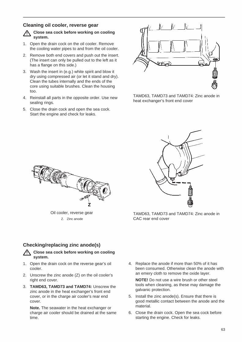
63
Oil cooler, reverse gear
Z. Zinc anode
Cleaning oil cooler, reverse gearClose sea cock before working on coolingsystem.
1. Open the drain cock on the oil cooler. Removethe cooling water pipes to and from the oil cooler.
2. Remove both end covers and push out the insert.(The insert can only be pulled out to the left as ithas a flange on this side.)
3. Wash the insert in (e.g.) white spirit and blow itdry using compressed air (or let it stand and dry).Clean the tubes internally and the ends of thecore using suitable brushes. Clean the housingtoo.
4. Reinstall all parts in the opposite order. Use newsealing rings.
5. Close the drain cock and open the sea cock.Start the engine and check for leaks.
Checking/replacing zinc anode(s)Close sea cock before working on coolingsystem.
1. Open the drain cock on the reverse gear’s oilcooler.
2. Unscrew the zinc anode (Z) on the oil cooler’sright end cover.
3. TAMD63, TAMD73 and TAMD74: Unscrew thezinc anode in the heat exchanger’s front endcover, or in the charge air cooler’s rear endcover.
Note. The seawater in the heat exchanger orcharge air cooler should be drained at the sametime.
TAMD63, TAMD73 and TAMD74: Zinc anode inCAC rear end cover
4. Replace the anode if more than 50% of it hasbeen consumed. Otherwise clean the anode withan emery cloth to remove the oxide layer.
NOTE! Do not use a wire brush or other steeltools when cleaning, as these may damage thegalvanic protection.
5. Install the zinc anode(s). Ensure that there isgood metallic contact between the anode and thematerial.
6. Close the drain cock. Open the sea cock beforestarting the engine. Check for leaks.
TAMD63, TAMD73 and TAMD74: Zinc anode inheat exchanger’s front end cover

64
Removing the seawater pumpClose sea cock before working on coolingsystem.
1. Drain the water from the seawater system.
2. Release the coolant pipes to and from the pump.
3. TAMD73 and TAMD74: Remove the bracebetween the heat exchanger and the timingcover (seawater pump).
4. Remove the pump from the timing cover.
Replacing the seawater pump impellerClose sea cock before working on coolingsystem.
1. Remove the pump’s end cover. Pull and twist outthe pump impeller using pliers.*
2. Clean inside the housing. Lubricate the pumphousing and the inside of the cover with a smallamount of natural soap.
3. Push in the new impeller with a rotating move-ment:
TAMD63, TAMD73 and TAMD74 – clockwise .TAMD71 – counterclockwise .
4. Reinstall the cover together with a new gasket.
Always keep a spare pump impeller andgasket on board.
5. Open sea cock. Start the engine and check forleaks.
*Note. In certain installations it is easier to first remove thepump from the engine (see next section) and then replace theimpeller.
Removing the seawater pump impeller
Installing the seawater pump1. Check that the O-ring is not damaged and that it
is in place on the pump.
2. Install pump and tighten in position.
3. TAMD73 and TAMD74: Install brace betweenthe heat exchanger and the timing cover (seawa-ter pump).
4. Lubricate sealing rings and install coolant pipesto and from the pump.
TAMD73 and TAMD74: Check for leakage at thesealing against the charge air cooler (CAC).
TAMD73 and TAMD74: Removing the seawaterpump

65
Technical descriptionElectrical systemThese engines have an electrical system with a generous generator capacity for a normal-sized boat. When amore powerful power supply is required, we recommend that you fit an extra generator or install a separate genera-tor unit.
These engines have a two-pole electrical system with an AC generator. The system voltage is 12V or 24V. TheTAMD71 has an electrical starter element (air preheating) fitted as standard. In these engines, the starter elementfacilitates starting a cold engine and reduces exhaust smoke when starting in cold weather. In the TAMD63,TAMD73 and TAMD74, which all have higher compression, different combustion chambers and a modified injec-tion system, a starter element is not required.
The electrical system also includes senders formonitoring the engine’s coolant temperature and oilpressure.
The electrical system is shown in two ways. Thewiring diagrams (pages 73–93) shows the wiring,cable areas and cable colors. The positions of therespective parts in the engine/reverse gear are shownin the figures on pages 65–67.
Positions of electrical components inengine and reverse gear:
TAMD63
TAMD63
Note. The components in the figuresare numbered the same as in theengine’s wiring diagram on page 75.
3. Starter motor4. Generator5. Starter relay6. Semi-automatic fuses7. Oil pressure sender, reverse gear8. Pressure sender, Turbo boost pressure9. Solenoid valve (fuel cut off valve)
10. Coolant temperature switch11. Engine coolant temperature sender12. Oil pressure switch, engine13. Oil pressure sender, engine14. Engine speed (rpm) sender

66
TAMD71B
TAMD71B
Note. The components in the figures are numbered the sameas in the engine’s wiring diagram on page 77.
3. Solenoid (fuel shut-off valve) 13. Relay for starter element4. Generator 14. Time relay5. Starter motor 15. Oil pressure sender, reverse gear6. Fuse for fuel shut-off valve 16. Pressure sender, Turbo boost pressure7. Stop relay 17. Oil pressure sender, engine8. Starter relay 18. Oil pressure switch, engine9. Semi-automatic fuses 19. Engine coolant temperature sender
11. Starter element 20. Coolant temperature switch12. Fuse for starter element 21. Engine speed (rpm) sender
Starter element (TAMD71B)
The starter element heats the inlet air to the engine.The element consists of three series connected wireelements installed in a connecting pipe. It is locatedbetween the turbocharger and the engine intakemanifold. The element is automatically engaged whenstarting when the starter key is turned to and passesthe pre-heating position (II). This sends a voltagepulse to a time relay, which in turn controls engage-ment of the element via a control relay. The engage-ment time is approx. 50 sec.
See wiring diagram on page 77. Starter element

67
TAMD73, TAMD74
Electronic Diesel Control (EDC) system(TAMD73P and TAMD74)
The injection pump on the TAMD73P and TAMD74engines has an electronic governor. The governorcontains an electro-magnet which effects the injectionpump control rod and so the amount of fuel injected(engine output).
The EDC system measures boost pressure andcharge air temperature and calculates the available airmass. This determines the amount of fuel injected(smoke limiter function). To achieve minimal emis-sions at start the system measures the engine cool-ant temperature and adapts the amount of fuel re-quired.
The system also determines the maximum torqueavailable at the engine speed registered withoutrisking damaging the engine. To protect the engine athigh engine coolant temperatures, high charge airtemperatures or excessive charge air pressure theEDC temporarily reduces the amount of fuel (reducedengine output) until the current values normalize.
The EDC control module also has a diagnosticssystem (On-board diagnostics OBD) which assistsusers/service technicians to quickly determine thecause of any malfunctions on the system using thediagnostic lamp or a diagnostic scan tool (“DiagnosticKey”).
TAMD73, TAMD74
Note. The components in the figures are numberedthe same as in the engine’s wiring diagram on pages79, 81, 83, 85 and 87.
3. Generator4. Starter motor5. Starter relay6. Main relay7. Electronic Diesel Control (EDC) control module
box* (incl. fuel temperature sender, EDC andturbo pressure sender, EDC)
8. Stop relay9. Semi-automatic fuses
10. Oil pressure sender, reverse gear11. Boost pressure sender, (instrument)12. Oil pressure switch, engine13. Oil pressure sender, engine14. Engine coolant temperature (ECT) sender, instrument19. Charge air temperature sender*20. Engine coolant temperature (ECT) sender (EDC)*21. Position sensor, control rod*22. Engine speed (RPM) sender*23. Electro-magnetic actuator, EDC*24. 2-pin connector, data link connector (DLC)*25. Fuse for EDC system (TAMD74)
* Note. Apply to TAMD73P and TAMD74 engines.

68
Starter motorThe starter motor is mounted on the flywheel casingon the right of the engine.
When the starter motor is engaged, a drive on thestarter motor’s rotor shaft is moved in an axial direc-tion so that it engages with a spur ring on the engine’sflywheel. The drive’s axial movement and the engage-ment of the starter motor are controlled by a controlsolenoid on the starter motor.
The starter motor’s control solenoid is engaged in turnvia the starter relay* when the starter key is held inposition III.
* Pos. 5 on the overview illustration on pages 65 and 67 or pos. 8on the illustration on page 66.
Connecting the sensor system
Turn the engine off and switch off power atthe main switches before carrying out workon the electrical system.
1. Disconnect the yellow sensor cable from the B+connection on the generator.
2. Splice the cable (yellow, 1.5 mm2) and route it tothe batteries. Connect the cable to the batteries’positive (+) pole.
Charging control lamp (extra generator)
A separate charging control lamp (3W) can be con-nected to the extra 28V/100A generator.
A resistor (3) P/N 863400-8 (47Ω/25W) must also beconnected as shown in a separate wiring diagram onpage 73.
Fuel shut-off valveTAMD63, TAMD71B and TAMD73WJ engines arestopped via a solenoid valve (fuel shut-off valve)which is activated during stopping. The valve changesthe direction of the fuel flow to and from the feedpump so that a vacuum is created in the fuel chamberof the injection pump. This makes it impossible for thepump element to fill up and the engine stops.
This valve is located on a bracket beneath the injec-tion pump.
AC generatorThe generator is belt driven and located at the front ofthe engine.
The engine’s standard generator can be fitted with acharge distributor as an accessory. Two independentbattery circuits can then be charged simultaneously.The charge distributor separates the two groups fromone another so that the engine’s storage batteries arekept fully charged even if the “accessory batteries”are weak or almost discharged.
Note. The charging voltage from the 28V/60A genera-tor is thermally compensated. The voltage increasesat low temperatures and is reduced at higher tempera-tures.
Voltage regulator with sensor system
The voltage regulator for the standard generator (14V/60A, or 28V/40A* or 28V/60A) has a sensor system.
This sensor system compares the charging voltagebetween the generator’s B+ and B– connections withthe charging voltage between the batteries’ positiveand negative poles. The voltage regulator then com-pensates any drop in voltage in the leads between thegenerator and the batteries by increasing the chargingvoltage from the generator, if necessary.
When supplied by Volvo Penta, the sensor system isnot activated. However, it is likely that it was connect-ed when the engine was installed.
* Note. The 28V/40A generator is for the TAMD63 engine.
FusesThese engines have two semi-automatic fuses ofapprox. 8A. These fuses break the current in theevent of overloading.*
* TAMD73P, TAMD74: If a fuse blows the engine stops.

69
In the TAMD71B the fuses are located in the front ofthe junction box on the left end of the expansion tank.The electrical starter element is also protected by astrip fuse (150A) between the element and the hightension relay.
The TAMD63, TAMD73 and TAMD74 have the junc-tion box on the exhaust manifold at the rear left of theengine. The fuses are at the back of the box.
In the junction box there is also a replaceable safetyfuse (8A) for the fuel shut-off valve on the TAMD71Band a replaceable safety fuse* (7.5A) for the EDCpower supply on the TAMD74.
See instructions on page 71 for resetting/replacingfuses.
Make sure that you always have spare fuses onboard.
*TAMD74: If the fuse blows the engine stops.
The main switches should break the current to allparts consuming electricity. Electrical leads should berouted so that they are not exposed to moisture andthere is no risk of them being exposed to bilgewater inthe keelson.
If there are several battery circuits, there must beseparate switches for the extra equipment. Theremust also be a main switch between the extra bat-tery’s positive (+) pole and the fuse block for theboat’s electrical equipment. The main switch for theextra battery circuit should break the current to allpower consuming equipment connected to this circuitand be switched off when there is no requirement forextra current. The main switches to the engine mustbe switched off when the boat is not in use.
The propulsion unit must not be electrically connectedwith other equipment such as trim tabs, steps, etc.Neither may it be used as ground points for radio ornavigation installations or other electrical equipmentwith separate ground cables. All separate groundconnections should be collected together to form ajoint ground connection which is separate from thepropulsion package.
If shore power is connected, protector ground shouldnot be connected to the engine or to any other groundon the boat.
Transformers connected to shore power must beinstalled so that the protective ground on the inputside (120/220V) and the negative connection on theoutput side (12/24V) are not connected.
Warning! Electrolytic corrosion as a conse-quence of leakage currents may cause seriousand expensive damage to your boat’s equipmentwithin a short time. Work on the boat’s lowtension circuit should only be carried out byqualified or experienced persons. Installation orwork on the shore power equipment must onlybe carried out by electricians authorized to workwith high-voltage installations.
RelaysThe relays are located in the junction box. This islocated at the rear of the exhaust manifold on the leftside of the engine (TAMD63, TAMD73 and TAMD74)and on the left end of the expansion tank (TAMD71B).
The start and stop* functions are controlled via twochange-over relays. These relays are identical and aretherefore interchangeable if necessary.
On TAMD71B engines there is also a timer relay inthe junction box which controls the starter element’sengagement time via a high tension relay (approx. 50seconds). This high tension relay is located in front ofthe air cleaner (ACL) adjacent to the starter element.
*Not TAMD63 and TAMD73WJ engines.
General InformationElectrolytic corrosion
Your boat and its engine/reverse gear have sacrificialanodes made of zinc as protection against galvaniccorrosion. This protection may be rendered ineffectiveif there are any leakage currents from the electricalsystem due to faulty equipment or incorrectly con-necting electrical components on the negative side(grounding, protector ground). The following shouldalways be observed:
The main engine switches should be mounted on boththe positive (+) and the negative (–) battery leads.
Electrical system – Important!Turn the engine off and switch off power atthe main switches before carrying out workon the electrical system.
1. Main ON/OFF power switches
Never break the circuit between the generator andbatteries while the engine is running. In otherwords, the main switches must never be discon-nected before the engine has stopped. If thecircuit is broken while the engine is running, thevoltage regulator may be destroyed and thegenerator seriously damaged.
Charging circuits must not be switched over whilethe engine is running, for the same reason.

70
To simultaneously charge two independent batterycircuits, fit a Volvo Penta charge distributor to theregular generator (accessory).
2. Batteries
Never mix up the positive and negative batteryterminals when installing. Incorrect installation canresult in serious damage to electrical equipment.Refer to wiring diagrams. The battery terminalposts should always be well cleaned and thecable terminals well tightened and greased toprevent open circuits.
Avoid boost charging the batteries. If the batterymust be booster charged, first remove bothbattery leads.
NOTE! Follow relevant safety regulations whencharging batteries. When charging, unscrew fillerplugs but leave them in their holes. Ventilationshould be good, particularly if the batteries arebeing charged in an enclosed area. Always switchoff the charging circuit before removing thebattery charger connectors.
Warning! Never allow an open flame orelectric sparks near the batteries. Neversmoke in proximity to the batteries. Thebatteries give off hydrogen gas duringcharging which when mixed with air canform an explosive gas – oxyhydrogen. Thisgas is easily ignited and highly volatile.
Always use protective goggles whencharging and handling batteries.
The battery electrolyte contains extremelycorrosive sulfuric acid. If this should comein contact with the skin, immediately washwith soap and plenty of water. If battery acidcomes in contact with the eyes, immediate-ly flush with plenty of water and obtainmedical assistance without delay.
3. See separate instructions on this page for howto start using auxiliary batteries.
4. Connecting accessories and extra equipment
All extra equipment should be connected to aseparate junction box and fused. Extra outletsdirectly from the instrument panels should beavoided. Permitted extra power take-off is howev-er maximum 5A* (for all instrument panels togeth-er).
*Note. For the TAMD73P and TAMD74 max. 2A apply.
Arc weldingRemove the positive and negative leads from thebatteries. Then remove all leads to the generator.
TAMD73P and TAMD74: Remove the connector fromthe EDC system control module (located behind thefine fuel filters). Pull down the red locking catch (A)below the connector while pulling the connector out atthe same time.
Starting using auxiliary batteriesWarning!
The batteries (auxiliary batteries in particular) containextremely explosive oxyhydrogen gas. One spark,which may be formed if the auxiliary batteries areconnected incorrectly, is sufficient to explode abattery and cause damage and injury.
1. Check that the auxiliary batteries are connected(in series or in parallel) so that their rated voltageis the same as the engine’s system voltage.
2. First connect the red jump lead (+) to the auxiliarybattery, then to the discharged battery. Thenconnect the black jump lead (–) to the auxiliarybattery, then to a spot a short distance from thedischarged batteries , for example at the mainswitch on the negative cable or at the negativecable’s connection to the starter motor.
3. Start the engine. NOTE! Do not shift the con-nections when attempting to start the engine(spark risk) and do not lean over any of thebatteries.
4. Remove the jump leads in exactly the oppositeorder to which you put them on. NOTE! Thenormal leads to the standard batteries shouldunder no circumstances be moved.
TAMD73P and TAMD74: Removing the connectorfrom the control module
A. Locking catch
Always connect the weld clamp to the component tobe welded and as close to the welding point as possi-ble. The clamp should never be connected to theengine or in such a manner that the current is able topass over any bearings.
When welding is complete:
TAMD73P and TAMD74: Press the connector into thecontrol module for the EDC system while pushing thelocking catch (A) upwards.
Always connect the leads to the generatorbefore replacing the battery leads.

71
Maintenance – Electrical SystemNOTE! Always stop the engine and break thecurrent using the main switches beforeworking on the electrical system.
Also read the section entitled “Electricalsystem – Important” on pages 69–70.
TAMD63, TAMD73, -74 TAMD71B
Terminal box with fuses
A. Fuse for the EDC system (TAMD74)
Strip fuse for electrical starter element*
Note. This work should be left to authorizedservice personnel.
1. Stop the engine and break the circuit using themain switches.
2. Remove the cover plate over the high power relay.
* Note. For TAMD71B engines.
TAMD71B: Blade fuse (1) with support (2) forelectrical starter element
3. Remove the old fuse (1) complete with holder (2).
Note! When removing and tightening the nuts* onthe terminals on the starter element, these termi-nals must always be held tightly (see figure).Otherwise, the wire element may twist inside thestarter element and cause a short circuit.
4. Fit the new fuse and support as shown in theillustration. Reinstall the cover plate over therelay.
* Tightening torque for terminal nuts = 11–14 Nm (1.1–1.4 kpm/8–10 lbf.ft.).
TAMD71B: Removal/tightening terminal nuts onstarter element terminals
Resetting/replacing fusesEnsure that you use the correct rating for the fuseyou are replacing. Never fit a more powerful fuse.
Make sure that you always have spare fuses onboard.
Note. If the same fuse often trips or needs to bereplaced, consult authorized service personnel so thatthey can investigate the cause of the overload.
Semi-automatic fuses
The semi-automatic fuses are reset by pressing thebutton on the fuse.
Fuse for the EDC system*
The fuse (7.5A) can be replaced after removing thecover of the terminal box.
*Note. For TAMD74 engines.

72
Charge condition
Check the batteries’ charge condition using a hydrom-eter. The battery electrolytic density should be 1.28 g/cm3.* Charge battery if reading has dropped to 1.24 g/cm3* (approximately 75% charge).
Note. If an aerometer-type hydrometer (see illustra-tion) is used, the value read off applies at a tempera-ture of approx. +25°C (77°F). At other temperaturesthe reading must be compensated as follows:
at –20°C (–4°F) compensate by –0.03at –5°C (23°F) compensate by –0.02at +10°C (50°F) compensate by –0.01at +40°C (104°F) compensate by +0.01
Example: A value of 1.24 measured at –5°C (23°F)should be corrected to 1.22 which requires extracharging.
Note. An optical-type hydrometer is temperaturecompensated.
The various battery cells should display relativelyeven values. Uneven results may mean that thebattery is more or less ready for replacement.
* Note. For batteries with tropical acid substitute 1.24 g/cm3, and
1.20 g/cm3.
Aerometer-type Optical-type
Hydrometers
TAMD71B: Fuel shut-off valve fuse
Checking batteries and electricalconnections
Read the section entitled “Electrical system –Important” on pages 69–70.
The service life of your batteries depends largely onhow they are maintained. Keep batteries dry andclean. Dirt on the batteries may cause tracking anddischarge them, particularly in damp weather.
Clean the battery terminals and connections usingsuitable wire brushes. Poor contact may causeunnecessary voltage drops. Tighten the cable termi-nals well and spray the battery terminals and connec-tions with anti-corrosive agent or coat them withVaseline.
Check that the batteries are connected properly.
Also check that all other electrical connections are dryand free of oxidation and that there are no looseconnections. If necessary, spray these connectionswith a water-repellent spray (Volvo Penta Universaloil).
Cleaning the battery terminals
Fuel shut-off valve fuse*
1. Stop the engine and break the circuit using themain switches.
2. Detach the terminal box and pull it out.
3. Dismantle the fuse holder and replace the fusewith a new one (8A). See illustration.
4. Reinstall the terminal box.
* Note. For TAMD71B engines.

73
Wiring Diagrams
Connection of sensor system to standard generator,principle diagram
1. Sensor cable (yellow, 1.5 mm2) 6. Starter motor
2. Charge distributor (accessory) 7. Main ON/OFF power switch3. Voltage regulator 8. Accessory batteries (for4. Generator accessories)5. Fuse panel (accessory) 9. Start batteries (engine)
Block diagram
A. Main panel D. Alarm panel. (Used only when there is no mainB. Auxiliary panel panel A)C. Flying Bridge panel* E. Y connection
F. Junction box** with fuses
* Main panel (A) may also be installed on the ** Note. The picture shows the TAMD63, TAMD73flying bridge control position. and TAMD74.
Connecting the charge indicator lamp
Extra generator 28V/100A
1. Key switch2. Charge indicator light3. Resistor (47Ω/25W),
P/N 863400-84. Generator 28V/100A

TAMD63L-A, TAMD63P-AControl panel for auxiliary control position (Flying Bridge)
Cable areas in mm 2 are given after the color codes in the wiring diagrams.
The cable area is 1.0 mm 2 unless otherwise stated.
Instrument panel, (Master panel)
Spring loaded
Spring loaded
Instrument panels1. Instrument lighting2. Voltmeter3. Oil pressure gauge4. Engine coolant temperature gauge5. Connector for extra
warning display (accessory)6. Electronics module (alarm)7. Engine coolant temperature warning lamp8. Oil pressure warning lamp9. Charge warning lamp
10. Indicator lamp (not used)11. Switch, instrument panel lighting12. Alarm test/acknowledgement switch13. Tachometer with built-in hours run meter14. Key switch15. Alarm16. Connector for connecting neutral
position switch, if fitted (accessory)17. 16-pin connector18. 2-pin connector (for auxiliary panel,
where installed)

Aux
iliar
y pa
nel
1.In
stru
men
t lig
htin
g2.
Oil
pres
sure
gau
ge,
reve
rse
gear
3.T
urbo
cha
rgin
g pr
essu
re g
auge
4.C
onne
ctio
n to
inst
r. li
ght.
on m
ain
pane
l5.
Con
nect
ion
to p
rinte
d ci
rcui
t ca
rd o
n m
ain
pane
l6.
Con
nect
ion
to c
onne
ctor
(18
) on
mai
n pa
nel
Cab
le c
olor
BL
=B
lue
OR
=O
rang
eL
BL
=L
igh
t-b
lue
PU
=P
urp
leB
N=
Bro
wn
R=
Re
dL
BN
=Li
ght-
brow
nS
B=
Bla
ckG
N=
Gre
enW
=W
hite
GR
=G
ray
Y=
Ye
llow
Con
vers
ions
mm
2 /AW
G*
*A
mer
ican
Wiri
ng G
auge
mm
20.
751.
01.
52.
510
16A
WG
1816
(17
)15
(16
)13
75
Eng
ine
Not
e. T
he c
ompo
nent
s in
the
wiri
ngdi
agra
m h
ave
the
sam
e nu
mbe
rs a
ssh
own
in t
he k
ey d
iagr
ams
on p
age
65.
1.B
atte
ry2.
Mai
n O
N/O
FF
pow
er s
witc
h3.
Sta
rter
mot
or4.
Ge
ne
rato
r5.
Sta
rter
rel
ay*
6.S
emi-a
utom
atic
fus
es (
8A)
*7.
Oil
pres
sure
sen
der,
rev
erse
gea
r(0
– 3
0 ba
r)8.
Tur
bo p
ress
ure
send
er (
0 –
3 ba
r)9.
Sol
enoi
d va
lve
(fue
l cut
off
valv
e)10
.E
ngin
e co
olan
t te
mpe
ratu
re (
EC
T)
switc
h (9
7°C
nor
mal
ly o
pen
–cl
oses
if
faul
t oc
curs
)11
.E
ngin
e co
olan
t te
mpe
ratu
re (
EC
T)
send
er (
40 –
120
°C/1
04–2
48°F
)12
.O
il pr
essu
re s
witc
h, e
ngin
e (0
.7ba
r, n
orm
ally
ope
n –
clos
es if
fau
lto
ccu
rs)
13.
Oil
pres
sure
sen
der,
eng
ine
(0 –
10 b
ar)
14.
Eng
ine
spee
d (r
pm)
send
er15
.16
-pin
con
nect
or
*Loc
ated
in t
he ju
nctio
n bo
x
Sug
gest
ed c
onne
ctio
n of
oil
scav
-en
ging
pum
p (p
umpi
ng a
nd f
illin
g)
Cab
le a
rea
1.5
mm
2 .
A.
Fus
e (8
A/2
4V,
or 1
5A/1
2V)
Cab
le a
reas
in m
m2 a
re g
iven
afte
r the
col
or c
odes
inth
e w
iring
dia
gram
s.T
he c
able
are
a is
0.7
5 m
m2
unle
ss o
ther
wis
e st
ated
.
A b
roke
n lin
e in
dica
tes
a no
n-V
olvo
Pen
ta c
able
.
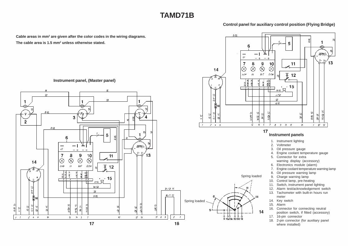
TAMD71BControl panel for auxiliary control position (Flying Bridge)
Cable areas in mm 2 are given after the color codes in the wiring diagrams.
The cable area is 1.5 mm 2 unless otherwise stated.
Instrument panel, (Master panel)
Spring loaded
Spring loaded
Instrument panels1. Instrument lighting2. Voltmeter3. Oil pressure gauge4. Engine coolant temperature gauge5. Connector for extra
warning display (accessory)6. Electronics module (alarm)7. Engine coolant temperature warning lamp8. Oil pressure warning lamp9. Charge warning lamp
10. Control lamp, pre-heating11. Switch, instrument panel lighting12. Alarm test/acknowledgement switch13. Tachometer with built-in hours run
meter14. Key switch15. Alarm16. Connector for connecting neutral
position switch, if fitted (accessory)17. 16-pin connector18. 2-pin connector (for auxiliary panel
where installed)

Auxiliary panel1. Instrument lighting2. Oil pressure gauge, reverse
gear3. Turbo charging pressure
gauge4. Connection to instr. light. on
main panel5. Connection to printed circuit
card on main panel6. Connection to connector (18)
on main panel
Conversions mm 2/AWG**American Wiring Gauge
mm2 1.0 1.5 2.5 10 16AWG 16 (17) 15 (16) 13 7 5
EngineNote. The components in the wiring diagramhave the same numbers as shown in thekey diagrams on page 66.
1. Battery2. Main ON/OFF power switch3. Fuel shut-off valve4. Generator5. Starter motor6. Fuel shut-off valve fuse (8A)7. Stop relay*8. Starter relay*9. Semi-automatic fuses (8A) *
10. Ground terminal*11. Starter element12. Fuse (150A) for starter element13. Relay for starter element14. Time relay for starter element*15. Oil pressure sender, reverse gear16. Pressure sender, Turbo boost pressure17. Oil pressure sender, engine18. Oil pressure switch, engine19. Engine coolant temperature sender20. Coolant temperature switch21. Engine speed (rpm) sender22. 16-pin connector*
* Located in the junction box
Suggested connection of oil scaveng-ing pump (pumping and filling)
Cable area 1.5 mm2.
A. Fuse (8A/24V, or 15A/12V)
NO = Normally open during operation
A broken line indicates a non-Volvo Penta cable.
Cable color
BL = Blue R = RedLBL = Light-blue SB = BlackBN = Brown TP = TransparentLBN = Light-brown (colorless)GN = Green VO = VioletGR = Gray W = WhiteOR = Orange Y = Yellow

Instrument panel, (Master panel)
Spring loaded
Spring loaded
Instrument panels1. Instrument lighting2. Voltmeter3. Oil pressure gauge4. Engine coolant temperature gauge5. Connector for extra warning
display (accessory)6. Electronics module (alarm)7. Engine coolant temperature warning
lamp8. Oil pressure warning lamp9. Charge warning lamp
10. Indicator lamp (not used)
11. Switch, instrument panel lighting12. Alarm test/acknowledgement switch13. Tachometer with built-in hours run
meter14. Key switch15. Alarm16. Connector for connecting neutral
position switch17. 16-pin connector18. 2-pin connector (for auxiliary panel
where installed)19. Adapter
TAMD73P-A (12V)Cable areas in mm 2 are given after the color codes in the wiring diagrams.
The cable area is 1.0 mm 2 unless otherwise stated.
Conversions mm 2/AWG
mm2 0.5 1.0 1.5 2.5 6 10AWG 20 16 (17) 15 (16) 13 9 (10) 7
Control panel for auxiliary control position (Flying Bridge)

Cable areas in mm 2 are given afterthe color codes in the wiring dia-grams.The cable area is 0.5 mm 2 unlessotherwise stated.
A broken line indicates a non-VolvoPenta cable.
Engine (12V system voltage)Note. The components in the wiring diagramhave the same numbers as shown in thekey diagrams on page 67.
1A. Starter battery1B. Emergency/auxiliary battery2 A. Main ON/OFF power switch2B. Main ON/OFF power switch for back-
up system3 . Generator4 . Starter motor5 . Starter relay*6 . Main relay*7 . EDC control module box8 . Stop relay*9 . Semi-automatic fuses (8A)*
10. Oil pressure sender, reverse gear11. Pressure sender, Turbo boost pressure12. Oil pressure switch, engine13. Oil pressure sender, engine14. Engine coolant temperature sender15. Joint splice16. 16-pin connector * (instrument cable
harness)17. 4-pin connector (reverse gear)18. Solenoid (reverse gear with electronic
shifting)19. Charge air temperature sender20. Engine coolant temperature (ECT)
sender (EDC)21. Position sensor, ** control rod22. Engine speed (rpm) sender**23. Electro-magnetic actuator, EDC**24. 2-pin connector, data link connector25. 16-pin connector (control unit)26. Connector27. Main power switch (control-/instrument
panels)
* Located in the junction box** Located on the injection pump
NO = Normally open during operation
Cable color
BL = Blue P = PinkLBL = Light-blue R = RedBN = Brown SB = BlackLBN = Light-brown VO = VioletGN = Green W = WhiteGR = Gray Y = YellowOR = Orange

Instrument panel, (Master panel)
Spring loaded
Spring loaded
Instrument panels1. Instrument lighting2. Voltmeter3. Oil pressure gauge4. Engine coolant temperature gauge5. Connector for extra warning
display (accessory)6. Electronics module (alarm)7. Engine coolant temperature warning
lamp8. Oil pressure warning lamp9. Charge warning lamp
10. Indicator lamp (not used)
11. Switch, instrument panel lighting12. Alarm test/acknowledgement switch13. Tachometer with built-in hours run
meter14. Key switch15. Alarm16. Connector for connecting neutral
position switch17. 16-pin connector18. 2-pin connector (for auxiliary panel
where installed)19. Adapter
Control panel for auxiliary control position (Flying Bridge)
TAMD73P-A (24V)Cable areas in mm 2 are given after the color codes in the wiring diagrams.
The cable area is 1,0 mm 2 unless otherwise stated.
Conversions mm 2/AWG
mm2 0.5 1.0 1.5 2.5 10AWG 20 16 (17) 15 (16) 13 7

Cable areas in mm 2 are given afterthe color codes in the wiring dia-grams.The cable area is 0.5 mm 2 unlessotherwise stated.
A broken line indicates a non-VolvoPenta cable.
Engine (24V system voltage)Note. The components in the wiring diagramhave the same numbers as shown in thekey diagrams on page 67.
1A. Starter battery1B. Emergency/auxiliary battery2 A. Main ON/OFF power switch2 B. Main ON/OFF power switch for back-
up system3 . Generator4 . Starter motor5 . Starter relay*6 . Main relay*7 . EDC control module box8 . Stop relay*9 . Semi-automatic fuses (8A)*10. Oil pressure sender, reverse gear11. Pressure sender, Turbo boost pressure12. Oil pressure switch, engine13. Oil pressure sender, engine14. Engine coolant temperature sender15. Joint splice16. 16-pin connector * (instrument cable
harness)17. 4-pin connector (reverse gear)18. Solenoid (reverse gear with electronic
shifting)19. Charge air temperature sender20. Engine coolant temperature (ECT)
sender (EDC)21. Position sensor, ** control rod22. Engine speed (rpm) sender**23. Electro-magnetic actuator, EDC**24. 2-pin connector, data link connector
(DLC)25. 16-pin connector (control unit)
* Located in the junction box**Located on the injection pump
NO = Normally open during operation
Cable color
BL = Blue P = PinkLBL = Light-blue R = RedBN = Brown SB = BlackLBN = Light-brown VO = VioletGN = Green W = WhiteGR = Gray Y = YellowOR = Orange

TAMD73WJ-AControl panel for auxiliary control position (Flying Bridge)
Cable areas in mm 2 are given after the color codes in the wiring diagrams.
The cable area is 1.5 mm 2 unless otherwise stated.
Instrument panel, (Master panel)
Spring loaded
Spring loaded
Instrument panels1. Instrument lighting2. Voltmeter3. Oil pressure gauge4. Engine coolant temperature gauge5. Connector for extra warning display
(accessory)6. Electronics module (alarm)7. Engine coolant temperature warning lamp8. Oil pressure warning lamp9. Charge warning lamp
10. Control lamp (not used)11. Switch, instrument panel lighting12. Alarm test/acknowledgement switch13. Tachometer with built-in hours run meter14. Key switch15. Alarm16. Connector for connecting neutral
position switch, if fitted (accessory)17. 16-pin connector18. 2-pin connector (for auxiliary panel
where installed)

Auxiliary panel1. Instrument lighting2. Oil pressure gauge, reverse gear3. Turbo charging pressure gauge4. Connection to instr. light. on main
panel5. Connection to printed circuit card
on main panel6. Connection to connector (18) on
main panel
Conversions mm 2/AWG**American Wiring Gauge
mm2 1.0 1.5 2.5 10 16AWG 16 (17) 15 (16) 13 7 5
Cable color
BL = BlueLBL = Light-blueBN = BrownLBN = Light-brownGN = GreenGR = GrayOR = OrangeP = PinkR = RedSB = BlackVO = VioletW = WhiteY = Yellow
EngineNote. The components in the wiring diagramhave the same numbers as shown in thekey diagrams on page 67.
1. Battery2. Main ON/OFF power switch3. Generator4. Starter motor5. Starter relay*9. Semi-automatic fuses (8A) *
10. Oil pressure sender, reverse gear11. Pressure sender, Turbo boost pressure12. Oil pressure switch, engine13. Oil pressure sender, engine14. Engine coolant temperature sender15. Ground terminal*16. Fuel shut-off valve17. Coolant temperature switch18. 16-pin connector*22. Engine speed (rpm) sender
* Located in the junction box
NO = Normally open during operation
A broken line indicates a non-VolvoPenta cable.
Suggested connection of oil scaveng-ing pump (pumping and filling)
Cable area 1.5 mm2.
A. Fuse (8A/24V, or 15A/12V)

Instrument panel, (Master panel)
Spring loaded
Spring loaded
Instrument panels1. Instrument lighting2. Voltmeter3. Oil pressure gauge4. Engine coolant temperature gauge5. Connector for extra warning
display (accessory)6. Electronics module (alarm)7. Engine coolant temperature warning
lamp8. Oil pressure warning lamp9. Charge warning lamp
10. Indicator lamp (not used)
11. Switch, instrument panel lighting12. Alarm test/acknowledgement switch13. Tachometer with built-in hours run
meter14. Key switch15. Alarm16. Connector for connecting neutral
position switch17. 16-pin connector18. 2-pin connector (for auxiliary panel
where installed)19. Adapter
Control panel for auxiliary control position (Flying Bridge)
TAMD74C-A, TAMD74L-A, TAMD74P-A (12V)Cable areas in mm 2 are given after the color codes in the wiring diagrams.
The cable area is 1.0 mm 2 unless otherwise stated.
Conversions mm 2/AWG
mm2 0.5 1.0 1.5 2.5 10AWG 20 16 (17) 15 (16) 13 7

Engine (12V system voltage)Note. The components in the wiring diagramhave the same numbers as shown in thekey diagrams on page 67.
1A. Starter battery1B. Emergency/auxiliary battery2 A. Main ON/OFF power switch2B. Main ON/OFF power switch for back-
up system3 . Generator4 . Starter motor5 . Starter relay*6 . Main relay*7 . EDC control module box8 . Stop relay*9 . Semi-automatic fuses (8A)*
10. Oil pressure sender, reverse gear11. Pressure sender, Turbo boost pressure12. Oil pressure switch, engine13. Oil pressure sender, engine14. Engine coolant temperature sender15. Joint splice16. 16-pin connector, male* (instrument
cable harness)17. 4-pin connector (reverse gear)18. Solenoid (reverse gear with electronic
shifting)19. Charge air temperature sender20. Engine coolant temperature (ECT)
sender (EDC)21. Position sensor, ** control rod22. Engine speed (rpm) sender**23. Electro-magnetic actuator, EDC**24. 2-pin connector, data link connector25. 16-pin connector, male (control unit)26. 16-pin connector, female (control unit)27. Fuse (7.5A)28. Connector29. Main power switch (control-/instrument
panels)
* Located in the junction box**Located on the injection pump
NO = Normally open during operation
Cable color
Refer to page 81.
Cable areas in mm 2 are given afterthe color codes in the wiring dia-grams.The cable area is 0.5 mm 2 unlessotherwise stated.
A broken line indicates a non-VolvoPenta cable.

TAMD74C-A, TAMD74L-A, TAMD74P-A (24V)Cable areas in mm 2 are given after the color codes in the wiring diagrams.
The cable area is 1.0 mm 2 unless otherwise stated.
Conversions mm 2/AWG
mm2 0.5 1.0 1.5 2.5 10AWG 20 16 (17) 15 (16) 13 7
Instrument panel, (Master panel)
Spring loaded
Spring loaded
Instrument panels1. Instrument lighting2. Voltmeter3. Oil pressure gauge4. Engine coolant temperature gauge5. Connector for extra warning display
(accessory)6. Electronics module (alarm)7. Engine coolant temperature warning
lamp8. Oil pressure warning lamp9. Charge warning lamp
10. Control lamp (not used)
11. Switch, instrument panel lighting12. Alarm test/acknowledgement switch13. Tachometer with built-in hours run
meter14. Key switch15. Alarm16. Connector for connecting neutral
position switch, if fitted (accessory)17. 16-pin connector18. 2-pin connector (for auxiliary panel
where installed)19. Adapter
Control panel for auxiliary control position (Flying Bridge)

Engine (24V system voltage)Note. The components in the wiring diagramhave the same numbers as shown in thekey diagrams on page 67.
1A. Starter battery1B. Emergency/auxiliary battery2 A. Main ON/OFF power switch2B. Main ON/OFF power switch for back-
up system3 . Generator4 . Starter motor5 . Starter relay*6 . Main relay*7 . EDC control module box8 . Stop relay*9 . Semi-automatic fuses (8A)*
10. Oil pressure sender, reverse gear11. Pressure sender, Turbo boost pressure12. Oil pressure switch, engine13. Oil pressure sender, engine14. Engine coolant temperature sender15. Joint splice16. 16-pin connector, male* (instrument
cable harness)17. 4-pin connector (reverse gear)18. Solenoid (reverse gear with electronic
shifting)19. Charge air temperature sender20. Engine coolant temperature (ECT)
sender (EDC)21. Position sensor, ** control rod22. Engine speed (rpm) sender**23. Electro-magnetic actuator, EDC**24. 2-pin connector, data link connector25. 16-pin connector, male (control unit)26. 16-pin connector, female (control unit)27. Fuse (7.5A)
* Located in the junction box**Located on the injection pump
NO = Normally open during operation
Cable color
Refer to page 81.
Cable areas in mm 2 are given afterthe color codes in the wiring dia-grams.The cable area is 0.5 mm 2 unlessotherwise stated.
A broken line indicates a non-VolvoPenta cable.
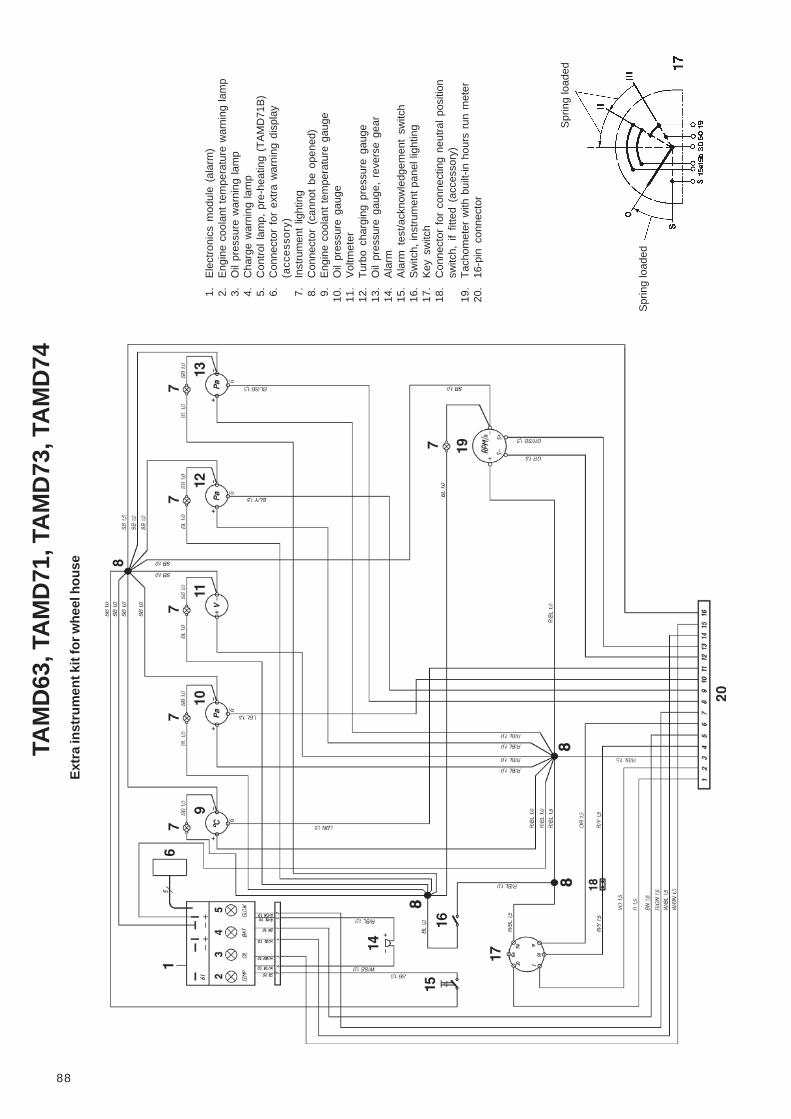
88
TAM
D63
, TA
MD
71, T
AM
D73
, TA
MD
74E
xtra
inst
rum
ent k
it fo
r whe
el h
ouse
1.E
lect
roni
cs m
odul
e (a
larm
)2.
Eng
ine
cool
ant
tem
pera
ture
war
ning
lam
p3.
Oil
pres
sure
war
ning
lam
p4.
Cha
rge
war
ning
lam
p5.
Con
trol
lam
p, p
re-h
eatin
g (T
AM
D71
B)
6.C
onne
ctor
for
ext
ra w
arni
ng d
ispl
ay(a
cce
sso
ry)
7.In
stru
men
t lig
htin
g8.
Con
nect
or (
cann
ot b
e op
ened
)9.
Eng
ine
cool
ant
tem
pera
ture
gau
ge10
.O
il pr
essu
re g
auge
11.
Vol
tmet
er12
.T
urbo
cha
rgin
g pr
essu
re g
auge
13.
Oil
pres
sure
gau
ge,
reve
rse
gear
14.
Ala
rm15
.A
larm
tes
t/ack
now
ledg
emen
t sw
itch
16.
Sw
itch,
inst
rum
ent
pane
l lig
htin
g17
.K
ey s
witc
h18
.C
onne
ctor
for
con
nect
ing
neut
ral
posi
tion
switc
h, i
f fit
ted
(acc
esso
ry)
19.
Tac
hom
eter
with
bui
lt-in
hou
rs r
un m
eter
20.
16-p
in c
onne
ctor
Spr
ing
load
ed
Spr
ing
load
ed

89
Flying Bridge instrument kit
1. Electronics module (alarm)2. Connector for extra warning display
(accessory)3. Engine coolant temperature warning lamp4. Oil pressure warning lamp5. Charge warning lamp6. Control lamp, pre-heating (TAMD71B)7. Alarm8. Alarm test/acknowledgement switch9. Switch, instrument panel lighting
10. Connector (cannot be opened)11. Instrument lighting12. Tachometer with built-in hours run meter13. Starter button14. Stop button15. Connector for connecting neutral position
switch, if fitted (accessory)16. 16-pin connector
Cable color
BL = BlueLBL = Light-blueBN = BrownLBN = Light-brownGN = GreenGR = GrayOR = OrangeP = PinkR = RedSB = BlackVO = VioletW = WhiteY = Yellow
Cable areas in mm 2 are given after thecolor codes in the wiring diagrams.
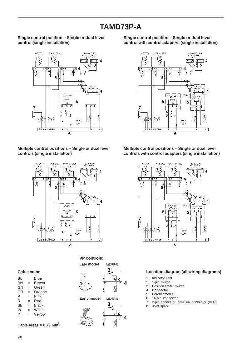
90
TAMD73P-A
Cable color
BL = BlueBN = BrownGN = GreenOR = OrangeP = PinkR = RedSB = BlackW = WhiteY = Yellow
Cable areas = 0.75 mm2.
Multiple control positions – Single or dual levercontrols (single installation)
Single control position – Single or dual levercontrol (single installation)
Location diagram (all wiring diagrams)1. Indicator light2. 1-pin switch3. Position limiter switch4. Connector5. Potentiometer6. 16-pin connector7. 2-pin connector, data link connector (DLC)8. Joint splice
Single control position – Single or dual levercontrol with control adapters (single installation)
Multiple control positions – Single or dual levercontrols with control adapters (single installation)
VP controls:Late model NEUTRAL
Early model NEUTRAL

91
Multiple control positions – Single or dual lever controls (twin engine installation)
Multiple control positions – Single or dual lever controls with control adapters (twin engine installation)
Cable color
BL = BlueBN = BrownGN = GreenOR = OrangeP = PinkR = RedSB = BlackW = WhiteY = Yellow
Cable areas = 0.75 mm2.
Location diagram (both wiring diagrams)1. Indicator light2. Switch3. Connector4. Relay5. Position limiter switch6. Potentiometer7. Connector, Port – Starboard cable harness8. 2-pin connector, data link connector (DLC)9. 16-pin connector, Port engine
10. 16-pin connector, Starboard engine
TAMD73P-A
VP controls:Late model NEUTRAL
Early model NEUTRAL

92
TAMD74Electronic controlSingle engine installation.Single or dual control lever unit
Mechanical controlSingle engine installation. Single or dual controllever unit with control unit adapters
Cable colors
BL = BlueBN = BrownGN = GreenOR = OrangeP = PinkR = RedSB = BlackW = WhiteY = Yellow
Cable areas = 0.75 mm2.
Location diagram1. Push button with indicator light, neutral – green2. Push button with indicator light, diagnostic – yellow3. Push button with indicator light, active station – red4. Connector5. Potentiometer, throttle/shifting
5a. Control unit adapter, throttle5b. Control unit adapter, shifting
6. Neutral switch7. 8-pin connector (male)8. 8-pin connector (female)9. Joint splice

93
TAMD74Electronic controlTwin engine installation. Single lever twin control
Mechanical controlTwin engine installation. Single or dual lever twin control with control unit adapter
Cable colors
BL = BlueBN = BrownGN = GreenOR = OrangeP = PinkR = RedSB = BlackW = WhiteY = Yellow
Cable areas = 0.75 mm2.
Location diagram (both wiring diagrams)1. Push button with indicator light,
Neutral – green2. Push button with indicator light,
Diagnostic – yellow3. Push button with indicator light,
Active station – red4. Push button with indicator light,
Synchro – blue5. Push button with indicator light,
Neutral – green6. Push button with indicator light,
Diagnostic – yellow
7. Connector8. Connector, Port – Starboard cable harness9. Relay
10. Potentiometer, throttle/shifting10a. Control unit adapter, throttle10b. Control unit adapter, shifting11. 8-pin connector (male) – port engine12. 8-pin connector (female) – starboard
engine13. Neutral switch

94
InhibitingWARNING! Observe the following rules whencleaning with high-pressure water jets. Neverdirect the water jet at seals, rubber hoses orelectrical components. Never use a high pres-sure jet when washing the engine.
Vent the fuel system according to the instructionson page 54. Start the engine and run on fast idleuntil approx. 2 liters (0.5 US gals) have been usedfrom the can.
Stop the engine and drain or pump the lubricatingoil from the oil sump. Connect the regular fuellines.
6. Check that the coolant in the freshwater systemhas sufficient antifreeze and top up if required. Ordrain the coolant. Close the sea cock and drainthe water from the seawater system. See pages32–33.
Remove the seawater pump impeller.
7. Check that the batteries are kept well charged. Adischarged battery may easily burst.
Batteries always have a certain amount of self-discharge which increases the higher the tempera-ture. Batteries in storage should therefore be keptas cool as possible. They should be stored dryand clean and normally charged when the electro-lyte density drops below 1.24 g/cm3 (1.20 g/cm3
for batteries with tropical acid).
You should preferably remove the batteries andhand them in for maintenance charging as in-structed by the manufacturer.
See also point 2 under the heading “ElectricalSystem – Important” on page 70.
8. When necessary, improve the external rustprotection by brushing on anti-corrosion oil. Thesurfaces should be clean and dry before beingtreated.
NOTE! Certain engine conservation oils areinflammable. Some of them are also dangerous ifinhaled. Ensure that ventilation in the work placeis good. Use a protective mask when spraying.
9. Stick a label on the engine stating the date ofinhibition, type of inhibition and the inhibiting oilused.
10. Cover the engine’s air intake, exhaust port andthe engine itself if so required.
Launching proceduresCheck the condition of the propeller(s). Damagedpropellers should be reconditioned or replaced.
Boat unused for up to two monthsIf the boat is not expected to be used for up to twomonths, it is sufficient to start the engine and warm itup once a fortnight.
If there is a danger of freezing, the cooling system’sseawater circuit should be drained after stopping.Check/top up the freshwater system’s antifreeze toprevent damage. Drain the freshwater tank if installed.
Remove the drain plug (if fitted) on the exhaust pipecondensed water collector. Drain the water from anylow-lying parts on the exhaust pipe.
Check the batteries’ charge condition. A dischargedbattery may easily burst.
Boat unused for more than two months1. Warm the engine up to normal operating tempera-
ture.
2. Check that the lubricating oil level in the reversegear reaches the upper mark (“FULL”) on thedipstick. Check the level with the engine idlingand the control in neutral.
3. Stop the engine and drain or pump the lubricatingoil from the oil sump.
4. Boat unused for up to max. 8 months: Replacethe lubricating oil filter and fill with Volvo Pentalubricating oil to the normal level. Warm theengine up after changing the oil.
5. Boat unused for more than 8 months: Fill theengine with inhibiting oil to just above the lowerpart of the mark on the dipstick. The oil compa-nies sell inhibiting oil.
Connect the fuel lines (suction and return) to acan filled with 1/3 inhibiting oil and 2/3 diesel.Some oil companies sell a ready-mixed oil for thispurpose.

95
Bringing out of storage
1. Remove any protective cover over the engine, airintake and exhaust pipe.
2. Remove any external inhibitors using white spirit.
3. Close the drain cocks and fit the drain plugs. Fitthe seawater pump impeller using a rotatingmovement:
TAMD63, TAMD73 and TAMD74 – clockwise .TAMD71 – counterclockwise .
Fill the freshwater system if the coolant has beendrained. See “Filling coolant” on page 59. Forcoolant information, refer to page 96.
4. If necessary, fill the engine with lubricating oil ofthe correct quality. Fit a new oil filter if this hasnot been done when changing the oil duringinhibiting. Check the oil level in the reverse gear.
5. Check the batteries as described on page 72.Reconnect batteries.
6. Fit new fuel filters and vent the fuel system asdescribed on pages 53–55.
7. Open sea cock. Start the engine (see “Operation”)and warm the engine up at a fast idle beforeloading the engine.
8. Check for any leaks of oil, fuel or cooling water.

96
Fuel, Oils, Coolant
Diesel fuelsThe composition of the fuel is vital for operation of theengine, its service life, and emissions. To meet theperformance specified and to run your boat cleanlyand quietly, it is vital that you use fuel as recommend-ed below.
Fuel specification
Fuel must meet national and international standards.For example:
– EN 590 (with national environmental and coldweather standards)
– ASTM-D975 No. 1-D, 2-D– JIS KK 2204
Sulfur content: According to statutory requirements.
Note. Large variations occur in merchant fuel specifi-cations which have influence on engine power outputand fuel consumption.
Declared power is measured with fuel acc. to ISO3046 with a lower calorific value of 42.700 kJ/kg and adensity of 840 g/liter at +15oC (59oF).
Lubricating oil, engineA lubricating oil of a quality as shown in the tablebelow should be used:
Designation Standard
VDS, VDS-2* Volvo Drain Specification
CD, CE API (American Petroleum Institute)
MIL-L-2104D US Government’s Military Spec.
*Note. A VDS oil must be used if there is to be a long periodbetween oil changes. See also the maintenance schedule and“Technical Data”.
We do not advise that you run on an oil of a qualitywhich does not meet the above requirements. This isa poor solution with respect to both economy andoperating safety.
For viscosity and capacities, see “Technical Data” onpage 108.
Lubricating oil, reverse gearFor the reverse gear , a single grade oil of qualityCC, CD or CE according to the API system should beused. Oil according to the MIL-L-2104D standard mayalso be used.
For quality and capacities, see “Technical Data” onpages 110–113.
Oil for servo unit system, hydraulic pump(accessory)
ATF oil* should be used in the servo unit system.
*ATF = Automatic Transmission Fluid (oil for automatic gear-boxes).
CoolantThe engine’s internal cooling system (freshwatersystem) is filled with a mixture of freshwater andadditives. NOTE! Never use freshwater withoutadditives. The following recommendations should befollowed to prevent frost and corrosion damage to yourengine:
If there is a risk of freezing
Use a mixture of 50% Volvo Penta antifreeze (glycol)and 50% pure water (as neutral as possible). Thismixture will protect against freezing to a tempera-ture of approx. – 40°C (–40°F) and should be usedall year round.
Note. There should be at least 40% antifreeze in thesystem for complete protection against corrosion.
NOTE! Glycol is harmful to health (danger-ous if ingested).
If there is no risk of freezing
When there is no risk of freezing water with addedVolvo Penta anti-corrosion agent* (P/N 1141526-2)may be used unless an anti-freeze mixture is used allyear round. Mixture ratio = 1:30.
See instructions on page 59 for topping up enginecoolant. Run the engine once the coolant has beentopped up to allow the additives to work.
NOTE! Anti-corrosive agents are harmful tohealth (danger if ingested).
* Note. Never mix antifreeze (glycol) and anti-corrosive agents.The two combined can produce foam and drastically reduce thecoolant’s effectiveness.
Replacing the coolant
The coolant should be replaced and the systemflushed at least once a year. See maintenance sche-dule.
Volvo Penta productsSee also under the heading “Accessories” on page115.

97
Fault-tracing1. Engine does not start
Starter motor does not turn engine over
CAUSE
The reverse gear is not disengaged (applies tocontrol with neutral position switch)
TAMD73P and TAMD74: The controls have notbeen calibrated
Discharged batteries
Main switches off
One of the semi-automatic fuses in the terminalbox has tripped (see page 71 for instructions onresetting fuses)
Poor contact/open-circuit in wiring
Key switch malfunction
Faulty starter relay
TAMD73P and TAMD74: Faulty main relay
Starter motor/solenoid (control solenoid) malfunc-tion
Water in the engine
*Note. TAMD63 and TAMD73WJ have no stop relay.
Starter motor turns over slowly
CAUSE
Discharged batteries
Poor contact, electrical cables
REMEDY
Put the reverse gear control lever into neutral
Calibrate controls as per instructions on pages 18–20
Charge/replace the batteries (or connect up auxiliarybatteries as shown on page 70)
Switch on the main switches
Reset the fuse by pressing in the button.
Rectify any open-circuits/loose connections. Checkfor oxidation on the contacts. If required, clean andspray connection with damp-inhibitor spray. See thewiring diagrams on pages 74–89.
Replace key switch
Replace start relay (or swap temporarily with stoprelay*)
Replace main relay (or swap temporarily with stoprelay)
Contact an authorized Volvo Penta service mechanic
Contact an authorized Volvo Penta service mechanic.Do not make repeated attempts to start the engine ifyou suspect water in the engine.
REMEDY
Charge/replace the batteries (or connect up auxiliarybatteries as shown on page 70)
Rectify any loose connections. Check for oxidation onthe contacts. If required, clean them and sprayconnections with damp-inhibitor spray.

98
Starter motor turns over but the engine doesnot start
CAUSE
Air in fuel lines
Lack of fuel
– fuel taps closed
– fuel tank empty/wrong tank on line
– fuel filters clogged (due to contaminants/paraffinprecipitation in the fuel as a result of low outsidetemperature)
TAMD63, TAMD71, TAMD73WJ: Solenoid valve(fuel shut-off valve) incorrectly connected
TAMD71B: Preheating insufficient
– incorrect starting method
– starter element not in circuit
TAMD73P and TAMD74: Faulty position sensor inthe governor
TAMD73P and TAMD74: Faulty rpm sensor in thegovernor
TAMD73P and TAMD74: Faulty actuator in thegovernor
REMEDY
Vent the fuel system as shown on page 54
Open the fuel cocks
Fill with fuel/connect the correct fuel tank
Fit new fuel filters (pre-filter and/or fine filters). Ventthe system as shown on page 54
Check solenoid valve has not been switched onunintentionally
Try to start engine again according to instructions onpage 23
Check that none of the semi-automatic fuses in theterminal box has tripped (see page 71 for instructionson resetting fuses)
Check the electrical leads and key switch, starterrelay and high power relay (swap the starter relaytemporarily with stop relay if required). Contact author-ized service mechanic if the starter element needs tobe replaced
Check for electronic diesel control (EDC) diagnostictrouble code (DTC) – refer to pages 102–105. Contactan authorized Volvo Penta service mechanic
Check for electronic diesel control (EDC) diagnostictrouble code (DTC) – refer to pages 102–105. Contactan authorized Volvo Penta service mechanic
Check for electronic diesel control (EDC) diagnostictrouble code (DTC) – refer to pages 102–105. Contactan authorized Volvo Penta service mechanic

99
2. Engine starts but stops again/runsunevenly
CAUSE
Air in fuel lines
Lack of fuel
– fuel taps closed
– fuel tank empty/wrong tank on line
– fuel filters clogged (due to contaminants/paraffinprecipitation in the fuel as a result of low outsidetemp.)
TAMD71B: Preheating insufficient
– incorrect starting method
– starter element not in circuit
Insufficient air supply to engine
– air cleaner filter clogged
Pressure line rupture
3. Engine coolant temperature too high
CAUSE
Coolant level in engine too low (air in system)
Thermostat malfunction
Faulty seawater pump (pump impeller)
Sea cock closed
Seawater intake blocked
Seawater filter blocked
Heat exchanger core clogged
Faulty circulation pump
REMEDY
Vent the fuel system as shown on page 54
Open the fuel cocks
Fill with fuel/connect the correct fuel tank
Fit new fuel filters (pre-filter and/or fine filters). Ventthe system as shown on page 54
Try starting again as shown on page 23
Check that none of the semi-automatic fuses in theterminal box has tripped (see page 71 for instructionson resetting fuses)
Check the electrical leads and key switch, starterrelay and hihg power relay (swap the starter relaytemporarily with stop relay if required). Contact author-ized service mechanic if the starter element needs tobe replaced
Fit a new air cleaner filter/clean air cleaner filter,check ventilation to engine compartment
Install new delivery pipe(s)
REMEDY
Fill the engine with coolant and vent the system asdescribed on pages 59– 60
Install a new thermostat
Replace the seawater pump impeller as shown onpage 64
Open the boat’s sea cock
Clean the seawater intake
Clean the seawater filter as shown on page 60
Clean the insert(s) as shown on pages 60–62
Contact an authorized Volvo Penta service mechanic

100
4. Coolant temperature too low
CAUSE
Thermostat malfunction
REMEDY
Install a new thermostat
5. Engine does not reach correct speedat wide open throttle (WOT)
CAUSE
Boat abnormally loaded
Fouling on underwater hull
Faulty/damaged propeller
Insufficient fuel flow
– fuel filters clogged (due to contaminants/paraffinprecipitation in the fuel as a result of low outsidetemperature)
Water in fuel
Insufficient air supply to engine
– air cleaner filter clogged
– air leak between turbo and engine’s inlet mani-fold
– dirt in turbocharger compressor
– faulty turbocharger
– poor engine compartment ventilation
Throttle controls incorrectly adjusted
Charge air cooler (CAC) clogged
TAMD71B: Faulty by-pass valve
High back pressure in exhaust system
Injector malfunction
TAMD73P and TAMD74: EDC system has tempo-rarily reduced engine output due to alarm limitbeing exceeded.
Faulty setting of injection pump
Fault in smoke limiter*
– smoke limiter seizing
– pressure pipe between inlet manifold and smokelimiter leaking
– faulty diaphragm in smoke limiter
– faulty setting
* TAMD73P and TAMD74 engines are not equipped with asmoke limiter.
REMEDY
If possible, reduce/redistribute the load
Clean the bottom of the boat and treat it with anti-fouling paint
Replace the propeller
Fit new fuel filters (pre-filter and/or fine filters). Ventthe system as shown on page 54
Clean fuel tank. Drain water from pre-filter if installed
Fit new air cleaner filter(s)/clean air cleaner filter
Check the rubber hose between the turbo and theconnecting pipe, plus other connections. Tighten thehose clips
Contact authorized service personnel
Contact authorized service personnel
Check that the ventilating ducts to the engine com-partment are not blocked
Adjust the throttle controls
Clean the insert(s) as shown on pages 60–62
Contact an authorized Volvo Penta service mechanic
Check that the exhaust pipe is not restricted in anyway
Get authorized service personnel to check the injec-tors
Check any diagnostic trouble codes (DTC) set, seepage 102. Correct malfunction cause
Contact an authorized Volvo Penta service mechanic
Contact an authorized Volvo Penta service mechanic
Fit a new pressure line
Contact an authorized Volvo Penta service mechanic
Contact an authorized Volvo Penta service mechanic
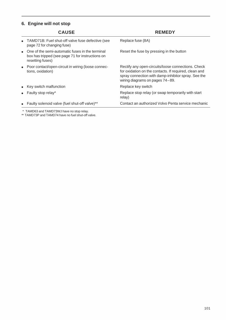
101
6. Engine will not stop
CAUSE
TAMD71B: Fuel shut-off valve fuse defective (seepage 72 for changing fuse)
One of the semi-automatic fuses in the terminalbox has tripped (see page 71 for instructions onresetting fuses)
Poor contact/open-circuit in wiring (loose connec-tions, oxidation)
Key switch malfunction
Faulty stop relay*
Faulty solenoid valve (fuel shut-off valve)**
* TAMD63 and TAMD73WJ have no stop relay.** TAMD73P and TAMD74 have no fuel shut-off valve.
REMEDY
Replace fuse (8A)
Reset the fuse by pressing in the button
Rectify any open-circuits/loose connections. Checkfor oxidation on the contacts. If required, clean andspray connection with damp-inhibitor spray. See thewiring diagrams on pages 74–89.
Replace key switch
Replace stop relay (or swap temporarily with startrelay)
Contact an authorized Volvo Penta service mechanic

102
If there are several diagnostic trouble codes (DTCs)stored the next code is flashed when the button ispushed again. When the first DTC is repeated, all thecodes have been read off.
Diagnostic Trouble Code(s) (DTCs) are stored untilerased. This should be done after the malfunction orsource of the DTC has been identified and repaired.
NOTE! If the On-board Diagnostics (OBD) systemhas triggered an event (for example stopped theengine) you must erase the DTC before the enginecan be restarted. Refer to Erasing DiagnosticTrouble Codes (DTC) below.
TAMD73P and TAMD74: EDC control panel –Single engine
TAMD73P and TAMD74: EDC control panel forone or more control stations (double installation)
1. Port engine2. Starboard engine
Erasing stored Diagnostic Trouble Codes (DTC)
Warning! Diagnostic trouble codes must notbe erased when the boat is in operation.
1. Turn the starter key to the stop position “S” andrelease the key.
2. Press the yellow Diagnostics button and hold itin while turning the starter key to the I (operating)position.
Erase the diagnostic trouble codes (DTCs) bykeeping the button pressed down for another 3seconds.
Note. If the diagnostics button is pressed againafter clearing the diagnostic trouble codes (DTCs)code 1.1 (No DTC stored) will be flashed out bythe system.
Reading off Diagnostic Trouble Codes (DTC)
To get a read-out from the system of what the natureof the fault is that is causing the diagnostic troublecode (DTC), press the yellow Diagnostics button whenthe light is flashing. This results in the system flash-ing a two-part code.* The first number of flashes areunits of ten, followed by a short pause, then a seriesof new flashes (single units).
After the alarm has been acknowledged (DTCs havebeen read off) the light will go out. Stored DTCs canbe read off again by pressing the yellow button.
Refer to the section EDC Diagnostic Trouble Codes(DTC) on pages 103–105 for an explanation of theflashed code sequences.
Note. Service technicians can obtain a more compre-hensive DTC read-out in plain language using thediagnostics Scan Tool (Diagnostic Key).
* Example: 2 flashes – pause – 6 flashes = DTC 2.6 Fault onthe control unit potentiometer.
Diagnostic functions – OBD system(TAMD73P and TAMD74)
The indicator lamp in the yellow Diagnostics buttonon the EDC system control panel starts to flash if thesystem receives abnormal signals or if there is amalfunction in the EDC system.
Press the button* for at least one second in order toread off the Diagnostic Trouble Code (DTC) and toacknowledge the alarm. A DTC message is flashed asa two-stage code.
* Note. When the engine is stopped the diagnostic trouble code(DTC) is flashed only after the EDC system is activated. Toactivate the EDC system turn the starter key to position “I”(operating position).
DIAGNOSIS
1 2DIAGNOSIS DIAGNOSIS

10
3
1.1 No fault
1.2 Control calibration(neutral position switch)
1.3 Control calibration(difference too small)
1.4 Control calibration(neutral position too short)
1.5 Control calibration(shift solenoid faulty)
1.6 Control calibration, mastercontrol station(calibration not carried out)
1.7 Control calibration, secondarycontrol position(calibration not carried out)
2.2 Control rod sensor
2.3 Control rod actuator
2.4/ Engine speed (rpm) sender2.5
On-board diagnostic (OBD) functionactivated.
Neutral position switch open orclosed at wrong point in relation topotentiometer value.
Angle between start of throttleopening and full throttle too small.
Neutral position switch closes withintoo short a range on the control.
Shift solenoid faulty, reverse gear(open-circuit, short-circuit).No current from main relay.
New installation.
New installation.
Control rod position sensor transmitsabnormal values to the controlmodule.
Control rod actuator takes too muchor little current.Open-circuit, connection 42.
Engine speed (RPM) sensor transmitsabnormal values to control module.
–
–
–
–
System does not enter calibration mode.
Starter motor cannot be activated.
Starter motor cannot be activated.
Engine stopped by system.
Main relay opens (engine stops).
Engine stopped by system.
EDC diagnostic Trouble Codes (DTC)
DTC Explanation Cause Reaction Action
–
Check operation of neutral position switch (closedin neutral position). Erase DTC.Recalibrate control.
Check potentiometer mounting.Erase DTC. Recalibrate control.
Adjust neutral position switch. Erase DTC.Recalibrate control.
Check solenoid connections. Check solenoids forshort/open circuit. Erase DTC. Recalibrate control.Check there is current from the main relay.
Calibrate controls. DTC erased automatically.
Calibrate controls. DTC erased automatically.
Check injection pump and control module connec-tions. Erase DTC. Start the engine.Contact authorized workshop if fault persists.
Check injection pump and control module connec-tions. Erase DTC. Start the engine.Contact authorized workshop if fault persists.
Check injection pump and control module connec-tions. Erase DTC. Start the engine.Contact authorized workshop if fault persists.

10
4 DTC Explanation C ause Reaction Action
System receiving no signals fromcontrol potentiometer.
System receiving no signals from shiftcontrol potentiometer.
Short-circuit or open-circuit in wiring/starter motor relay.
Short-circuit or open-circuit in wiring/main relay.
Short-circuit or open-circuit in Neutralindication cabling. Bulb malfunction.
Open or short-circuit in cabling or inreverse gear solenoid (actuator).
The system receives too high or too lowa boost pressure signal.
Faulty values from potentiometers,controls not calibrated, communicationfaults.
Faults in internal voltages in controlmodule.
Internal fault in control module.
Engine runs at constant 1000 rpm.
–
–
–
–
–
If the pressure is too high the systemwill reduce the volume of fuel injecteduntil pressure has normalized (turboprotection).
–
–
–
Check control potentiometer wiring and connec-tions and connections to control position. EraseDTC. Start the engine.If the fault persists shifting can be carried outdirectly on the reverse gear solenoids.
Check wiring/connections on shift control potenti-ometer and connections to control position. EraseDTC. Start the engine.If the fault persists shifting can be carried outdirectly on the reverse gear solenoids.
Check cabling and connections to starter relay interminal box. Check starter relay. Position 5 on thelocation diagram, page 67. Erase DTC.
Check cabling and connections to main relay interminal box. Check main relay. Position 6 on thelocation diagram, page 67. Erase DTC.
Check bulb in “Neutral” button. Check cabling andconnections to control position. Erase DTC.
Check reverse gear cabling and solenoids (actua-tors). Erase DTC.
Check air cleaner. Check the pressure line fromthe inlet manifold to the control module. EraseDTC. Contact authorized workshop for inspectionof turbocharger (TC).
Check potentiometers, wiring and connections tobuttons on flying bridge panel. Recalibrate controlif necessary. Erase DTC.
Erase DTC. Contact authorized workshop.
Erase DTC. Recalibrate control.Contact authorized workshop if recalibrationcannot be carried out.
2.6/ Control potentiometer2.7
3.1 Shift control potentiometer
4.6 Starter motor relay
5.1 Main relay
5.2 Neutral indication
5.4/ Shift – Forward/Reverse5.5
5.6 Boost pressure
6.4 Fault in MS module(MS = “Multi-Station”)
8.1 Control module
8.3 Read/write fault in controlcalibration

10
5
9.9 Fatal error on control module
Warning lamp – high enginecoolant temperature(in instrument panel)
Internal fault in program memory.
Engine coolant temperature too high.
System does not start.
If the engine coolant temperature is toohigh the system will reduce the volumeof fuel injected until temperature hasnormalized.
Turn off power completely and wait 3 minutesbefore reconnecting. Contact authorized workshopif fault persists.
Check the engine coolant system.
DTC Explanation Cause Reaction Action

106
Technical DataGeneral
TAMD63L-A, TAMD71BTAMD63P-A
No. of cylinders ..................................................... 6 6Swept volume ....................................................... 5.48 dm3 (liters), (334 in3) 6.73 dm3 (liters), (411 in3)Low idle ................................................................. 600 ±20 rpm 600 ±30 rpmValve clearance, stopped engine, cold or atoperating temperature:
intake ................................................................. 0.50 mm (0.0197") 0.40 mm (0.0157")exhaust .............................................................. 0.65 mm (0.0256") 0.55 mm (0.0217")
Compression pressure at starter motor speed(300 rpm) ............................................................... 2.2 MPa, (22 kp/cm2 = 313 psi) 2.2 MPa, (22 kp/cm2 = 313 psi)Weight, engine with heat exchanger, withoutreverse gear or clutch, approx. ............................ 745 kg (1643 lbs) 880 kg (1940 lbs)
TAMD73P-A, TAMD74C-A,TAMD73WJ-A TAMD74L-A,
TAMD74P-A
No. of cylinders .................................................... 6 6Swept volume ....................................................... 6.73 dm3 (liters), (411 in3) 7.28 dm3 (liters), (444 in3)Low idle ................................................................. 600 ±10 rpm* 600 ±10 rpm*Valve clearance, stopped engine, cold or atoperating temperature:
intake ................................................................. 0.50 mm (0.0197") 0.50 mm (0.0197")exhaust .............................................................. 0.65 mm (0.0256") 0.65 mm (0.0256")
Compression pressure at starter motor speed(300 rpm) ............................................................... 2.2 MPa, (22 kp/cm2 = 313 psi)Weight, engine with heat exchanger, withoutreverse gear or clutch, approx. ............................ 880 kg (1940 lbs) 860 kg (1896 lbs)
* Note! For TAMD73WJ 600 ±50 rpm applies.
At delivery, the idling speed for the TAMD73P andTAMD74 is adjusted to 600 rpm. If needed, the speed canbe adjusted within the range 550–700 rpm (refer to page21).
Furthermore, the speed is increased to 800 rpm duringmax. 2 minutes at coolant temperatures below +15°C(59°F) on these engine.
Cooling systemTAMD63L-A, TAMD71B TAMD73P-A,TAMD63P-A TAMD73WJ-A,
TAMD74C-A,TAMD74L-A,TAMD74P-A
Freshwater system capacity incl. heat exchanger,approx. .................................................................. 27 liters, 35 liters, 34 liters,
(7.1 US gals) (9.3 US gals) (9.1 US gals)Thermostat starts to open at (all engines) ........... 73–77°C (163–171°F)
fully open at (all engines) .................. 86–90°C (187–194°F)

107
Fuel systemTAMD63L-A, TAMD71BTAMD63P-A
Injection pump, settings,TAMD63L and TAMD71B ..................................... 16° ±0.5° BTDC 22° ±0.5° BTDCTAMD63P ............................................................. 15° ±0.5° BTDC –Injectors, opening pressure,TAMD63L and TAMD71B ..................................... 29 (+0.8) MPa, 30 (+0.8) MPa,
(295 (+8) kp/cm2 = 4206 psi) (306 (+8) kp/cm2 = 4351 psi)TAMD63P ............................................................. 30 (+0.8) MPa, –
(306 (+8) kp/cm2 = 4351 psi)Injectors, adjustment pressure (new spring):TAMD63L and TAMD71B .................................... 29.5 (+0.8) MPa, 30.5 (+0.8) MPa,
(300 (+8) kp/cm2 = 4279 psi) (311 (+8) kp/cm2 = 4424 psi)TAMD63P ............................................................. 30.5 (+0.8) MPa, –
(311 (+8) kp/cm2 = 4424 psi)
TAMD73P-A, TAMD74C-ATAMD73WJ-A TAMD74L-A
TAMD74P-AInjection pump, settings,TAMD73P and TAMD74 ...................................... 15° ±0.5° BTDC 11° ±0.5° BTDCTAMD73WJ ........................................................... 18° ±0.5° BTDC –Injectors, opening pressure ................................... 29.5 (+0.8) MPa, 29 MPa,
(300 (+8) kp/cm2=4279 psi) (295 kp/cm2=4206 psi)Injectors, adjustment pressure (new spring) ....... 29.5 (+0.8) MPa, 29.5 (+0.8) MPa,
(300 (+8) kp/cm2 =4279 psi) (300 (+8) kp/cm2 =4279 psi)
TurbochargerCharging pressure , min. values (measured in the engine’s inlet manifold at 100% load and wide open throttle(WOT), air temperature approx. +25°C (77°F). When measuring at a different temperature, the charging pressuremeasured must be corrected (see Workshop Manual).
If full power cannot be achieved, the pressure is considerably lower.
TAMD63L-A TAMD63P-A TAMD71BRating 5:
2400 rpm ............................................................ – 200 kPa –2600 rpm ............................................................ – 215 kPa 188 kPa2800 rpm ............................................................ 180 kPa 225 kPa –
Rating 4:2500 rpm ............................................................ – – 188 kPa2600 rpm ............................................................ – – 188 kPa
Rating 3:2500 rpm ............................................................ 180 kPa – –
Rating 2:2500 rpm ............................................................ 120 kPa – –
TAMD73P-A TAMD73WJ-A TAMD74P-ARating 5:
2600 rpm ............................................................ 230 kPa 175 kPa 215 kPa
Rating 4:2500 rpm ............................................................ 230 kPa – –2600 rpm ............................................................ 230 kPa 175 kPa –
TAMD74C-A TAMD74L-ARating 5:
2500 rpm ............................................................ – 205 kPa
Rating 4:2600 rpm ............................................................ 210 kPa –
Rating 3:2500 rpm (316 kW) ............................................ 205 kPa –2500 rpm (294 kW) ............................................ 195 kPa –

108
Lubrication systemTAMD63L-A, TAMD71B TAMD73P-A,TAMD63P-A TAMD73WJ-A,
TAMD74C-A,TAMD74L-A,TAMD74P-A
Oil pressure, hot engine at normal running rpm .... 300–550 kPa (3.0– 450–650 kPa (4.5–6.5 kp/cm2 =5.5 kp/cm2 = 43–80 psi) 61–94 psi)
at idling rpm ..................................... min. 150 kPa (1.5 kp/cm2 = min. 150 kPa (1.5 kp/cm2 =21 psi) 21 psi)
Max. engine inclination when running ................... 15° 15°
TAMD63L-A, TAMD71BTAMD63P-A
Oil capacity at oil change, without oil filter(s)*,approx.:
no engine inclination, Max. ................................ 20 liters (5.3 US gals) 27 liters (7.1 US gals)Min. ................................. 13 liters (3.4 US gals) 18 liters (4.8 US gals)
engine inclination 5°, Max. ................................. 16 liters (4.2 US gals) 23 liters (6.1 US gals)Min. ................................. 10 liters (2.6 US gals) 15 liters (4.0 US gals)
engine inclination 10°, Max. ............................... 12 liters (3.2 US gals) 17 liters (4.5 US gals)**Min. ................................ 7 liters (1.9 US gals) 12 liters (3.2 US gals)**
* Engine oil filter and by-pass filter have acapacity of approx. 0.5 liter (0.5 quart).
** At a rearward engine tilt of >5° oil dipstick part No.863166-5 should be used.
TAMD73P-A, TAMD74C-A,TAMD73WJ-A TAMD74L-A,
TAMD74P-AOil capacity at oil change, without oil filters*,approx.:
no engine inclination, Max. ................................ 28 liters (7.4 US gals) 25 liters (6.6 US gals)Min. ................................. 19 liters (5.0 US gals) 18 liters (4.8 US gals)
engine inclination 5°, Max. ................................. 24 liters (6.3 US gals) 20 liters (5.3 US gals)Min. ................................. 16 liters (4.2 US gals) 14 liters (3.7 US gals)
engine inclination 10°, Max. ............................... 18 liters (4.8 US gals)** 17 liters (4.5 US gals)**Min. ................................ 16 liters (4.2 US gals)** 12 liters (3.2 US gals)**
* Engine oil filter and by-pass filter have acapacity of approx. 0.5 liter (0.5 quart).
** At a rearward engine tilt of >5° the following oildipsticks should be used:– TAMD73, part No. 863166-5.– TAMD74, part No. 3827313-2.
Oil quality (all engines) .......................................... VDS (Volvo Drain Specification), orCD or CE in acc. with API system.
Viscosity at different ambient air temperatures .....(Temperature based on constant ambient airtemperature).
* Refers to synthetic or semi-synthetic oil.NOTE! Only SAE 5W/30 may be used.
SAE5W/30
−−−−−30 −−−−−20 −−−−−10 ±0 +10 20 30 40
−−−−−22 −−−−− 4 +++++14 32 50 68 86 104
−−−−−15oC SAE15W/40
−−−−−25oC SAE10W/30
−−−−−10oC SAE20W/30
±0oC SAE30
SAE40+10oC
oC
oF

109
Electrical systemTAMD63L-A, TAMD71BTAMD63P-A TAMD73P-A,
TAMD73WJ-A,TAMD74C-A,TAMD74L-A,TAMD74P-A
System voltage ..................................................... 12V (or 24V) 24V (or 12V)AC generator, voltage/max. amperage ................. 14V/60A (or 28V/40A) 28V/60A (or 14V/60A)AC generator, output approx. ................................ 840W (or 1120W) 1700W (or 840W)Alternative generator equipment (accessory):
for 12V system, voltage/max. amperage .......... 14V/130A 14V/130Aoutput approx. ......................... 1800 W 1800W
for 24V system, voltage/max. amperage .......... 28V/100A 28V/100Aoutput approx. ......................... 2800W 2800W
Battery capacity:for 12V system ................................................... 2 x 12 V connected in parallel, 2 x 12 V connected in parallel,
max. 110 Ah, (total max. 220 Ah) max. 110 Ah, (tot. max. 220 Ah)for 24V system ................................................... 2 x 12 V connected in series, 2 x 12 V connected in series,
max. 143 Ah max. 143 AhBattery electrolyte density at +25°C (77°F):
fully charged battery ........................................... 1,28 g/cm3 (1,24 g/cm3 )* 1,28 g/cm3 (1,24 g/cm3 )*charge battery at ................................................ 1,24 g/cm3 (1,20 g/cm3 )* 1,24 g/cm3 (1,20 g/cm3 )*
*Note: Applies to batteries with tropical acid.
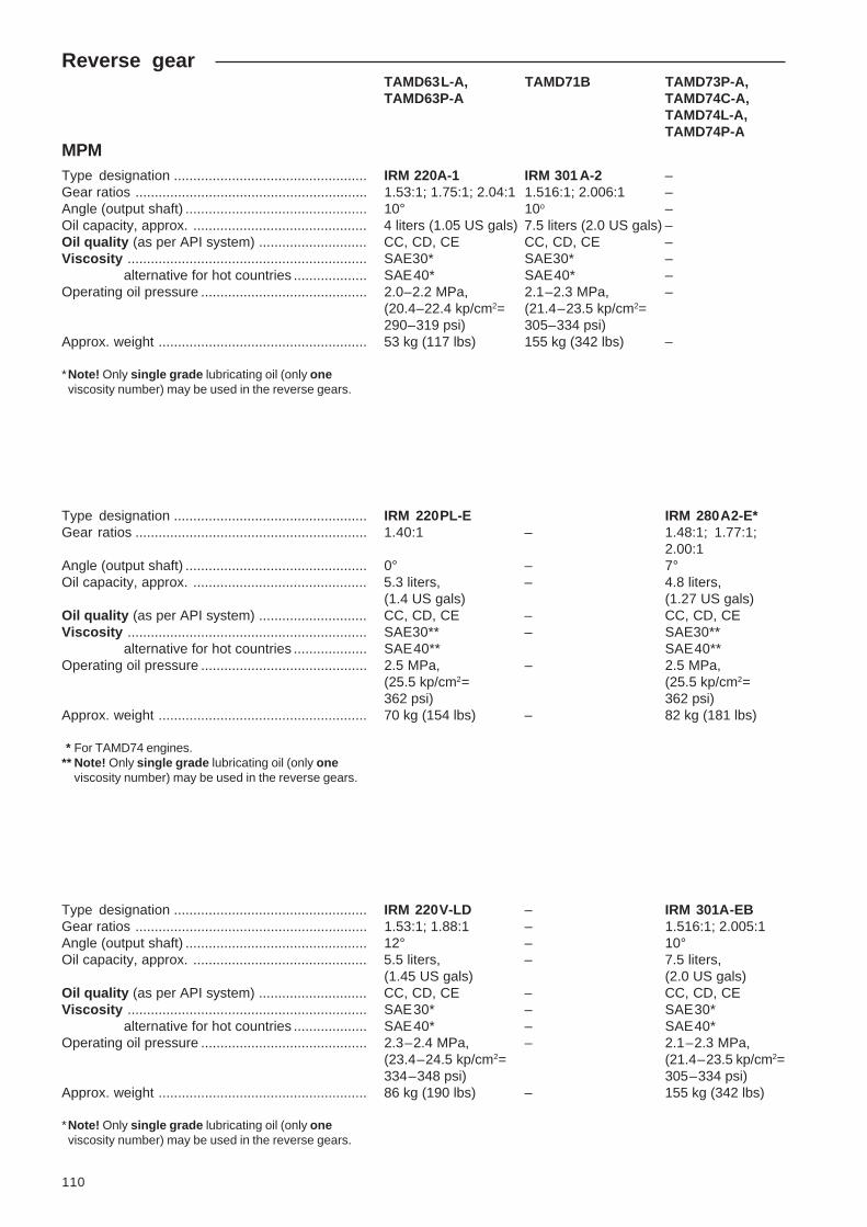
110
Reverse gearTAMD63L-A, TAMD71B TAMD73P-A,TAMD63P-A TAMD74C-A,
TAMD74L-A,TAMD74P-A
MPMType designation .................................................. IRM 220A-1 IRM 301 A-2 –Gear ratios ............................................................ 1.53:1; 1.75:1; 2.04:1 1.516:1; 2.006:1 –Angle (output shaft) ............................................... 10° 10o –Oil capacity, approx. ............................................. 4 liters (1.05 US gals) 7.5 liters (2.0 US gals) –Oil quality (as per API system) ............................ CC, CD, CE CC, CD, CE –Viscosity .............................................................. SAE30* SAE30* –
alternative for hot countries ................... SAE40* SAE40* –Operating oil pressure ........................................... 2.0–2.2 MPa, 2.1–2.3 MPa, –
(20.4–22.4 kp/cm2= (21.4–23.5 kp/cm2=290–319 psi) 305–334 psi)
Approx. weight ...................................................... 53 kg (117 lbs) 155 kg (342 lbs) –
*Note! Only single grade lubricating oil (only oneviscosity number) may be used in the reverse gears.
Type designation .................................................. IRM 220PL-E IRM 280A2-E*Gear ratios ............................................................ 1.40:1 – 1.48:1; 1.77:1;
2.00:1Angle (output shaft) ............................................... 0° – 7°Oil capacity, approx. ............................................. 5.3 liters, – 4.8 liters,
(1.4 US gals) (1.27 US gals)Oil quality (as per API system) ............................ CC, CD, CE – CC, CD, CEViscosity .............................................................. SAE30** – SAE30**
alternative for hot countries ................... SAE40** SAE40**Operating oil pressure ........................................... 2.5 MPa, – 2.5 MPa,
(25.5 kp/cm2= (25.5 kp/cm2=362 psi) 362 psi)
Approx. weight ...................................................... 70 kg (154 lbs) – 82 kg (181 lbs)
* For TAMD74 engines.** Note! Only single grade lubricating oil (only one
viscosity number) may be used in the reverse gears.
Type designation .................................................. IRM 220V-LD – IRM 301A-EBGear ratios ............................................................ 1.53:1; 1.88:1 – 1.516:1; 2.005:1Angle (output shaft) ............................................... 12° – 10°Oil capacity, approx. ............................................. 5.5 liters, – 7.5 liters,
(1.45 US gals) (2.0 US gals)Oil quality (as per API system) ............................ CC, CD, CE – CC, CD, CEViscosity .............................................................. SAE30* – SAE30*
alternative for hot countries ................... SAE40* – SAE40*Operating oil pressure ........................................... 2.3–2.4 MPa, – 2.1–2.3 MPa,
(23.4–24.5 kp/cm2= (21.4–23.5 kp/cm2=334–348 psi) 305–334 psi)
Approx. weight ...................................................... 86 kg (190 lbs) – 155 kg (342 lbs)
*Note! Only single grade lubricating oil (only oneviscosity number) may be used in the reverse gears.

111
TAMD63L-A, TAMD71B TAMD73P-A,TAMD63P-A TAMD74C-A,
TAMD74L-A,TAMD74P-A
Type designation .................................................. – – IRM 302V-LD-EB*Gear ratios ............................................................ – – 1.651:1; 2.184:1Angle (output shaft) .............................................. – – 15°Oil capacity, approx. ............................................ – – 8.5 liters,
(2.25 US gals)Oil quality (as per API system) .......................... – – CC, CD, CEViscosity .............................................................. – – SAE30**
alternative for hot countries ................. – – SAE40**Operating oil pressure .......................................... – – 2.05–2.15 MPa,
(20.9–21.9 kp/cm2=297–312 psi)
Approx. weight ...................................................... – – 127 kg (280 lbs)
* Reverse gear (V-drive) with electronically operatedshifting.
** Note! Only single grade lubricating oil (only oneviscosity number) may be used in the reverse gears.
Twin DiscType designation .................................................. MG5061A MG5061A MG5061A-E*Gear ratios ............................................................ 2.00:1 1.75:1; 2.00:1; 1.54:1; 1.75:1;
2.47:1 2.00:1Angle (output shaft) .............................................. 7° 7° 7°Oil capacity, approx. ............................................ 3.2 liters, 3.2 liters, 3.2 liters,
(0.85 US gals) (0.85 US gals) (0.85 US gals)Oil quality (as per API system) .......................... CC, CD, CE CC, CD, CE CC, CD, CEViscosity at oil temp. of 66–85°C (151–185°F) ... SAE30** SAE30** SAE30**
at oil temperature 85–100°C(185–212°F) ......................................... SAE40** SAE40** SAE40**
Working oil pressure at oil temperature of 82°C(180°F):
engaged, 1800 rpm ........................................... 2.3 MPa, 2.3 MPa, 2.3 MPa,(23.5 kp/cm² (23.5 kp/cm² (23.5 kp/cm²=334 psi) =334 psi) =334 psi)
at cruising speed, lowest .................................. 2.07 MPa, 2.07 MPa, 2.07 MPa,(21.1 kp/cm² (21.1 kp/cm² (21.1 kp/cm²=300 psi) =300 psi) =300 psi)
Approx. weight ...................................................... 113 kg (249 lbs) 113 kg (249 lbs) 113 kg (249 lbs)
* For TAMD73P-A engines.** Note! Only single grade lubricating oil (only one
viscosity number) may be used in the reversegears.

112
TAMD63L-A, TAMD71B TAMD73P-A,TAMD63P-A TAMD74C-A,
TAMD74L-A,TAMD74P-A
Type designation .................................................. MG5062V – MG5062V-E*Gear ratios ............................................................ 1.83:1; 2.07:1 1.53:1; 1.77:1;
2.05:1Angle (output shaft) .............................................. 15° – 15°Oil capacity, approx. ............................................ 5.6 liters, – 5.6 liters,
(1.5 US gals) (1.5 US gals)Oil quality (as per API system) .......................... CC, CD, CE – CC, CD, CEViscosity at oil temp. of 66–85°C (151–185°F) .. SAE30** – SAE30**
at oil temperature 80–99°C(176–210°F) ......................................... SAE40** – SAE40**
Working oil pressure at oil temperature of 82°C(180°F):
engaged, 1800 rpm ........................................... 2.05–2.2 MPa, – 2.05–2.2 MPa,(20.9–22.4 kp/cm²= (20.9–22.4 kp/
cm²=297–319 psi) 297–319 psi)
at cruising speed, lowest .................................. 1.9 MPa (19.3 – 1.9 MPa (19.3kp/cm² = 276 psi) kp/cm² = 276 psi)
Approx. weight ...................................................... 142 kg (313 lbs) – 142 kg (313 lbs)
* Reverse gear (V-drive) with electronically operatedshifting.
** Note! Only single grade lubricating oil (only oneviscosity number) may be used in the reversegears.
Type designation .................................................. – MG507-1 MG5075A-E*Gear ratios ............................................................ – 1.10:1; 1.51:1; 1.53:1; 1.77:1;
1.77:1; 1.98:1; 2.05:12.54:1; 2.99:1
Angle (output shaft) .............................................. – 0° 7°Oil capacity, approx. ............................................ – 6.7 liters, 5.9 liters,
(1.8 US gals) (1.6 US gals)Oil quality (as per API system) .......................... – CC, CD, CE CC, CD, CEViscosity at oil temp. of 66–85°C (151–185°F) .. – SAE30** –
at oil temperature 80–99°C(176–210°F) ......................................... – SAE40** –
Viscosity .............................................................. – – SAE40**Working oil pressure at oil temperature of 82°C(180°F):
engaged, 1800 rpm ........................................... – 2.05–2.2 MPa, 2.28 MPa,(20.9–22.4 kp/cm² = (23.2 kp/cm² =297–319 psi) 331 psi)
at cruising speed, lowest .................................. – 1.9 MPa (19.3 kp/cm²–= 276 psi)
Approx. weight ...................................................... – 178 kg (392 lbs) 140 kg (309 lbs)
* Reverse gear with electronically operated shifting.** Note! Only single grade lubricating oil (only one
viscosity number) may be used in the reversegears.

113
TAMD63L-A, TAMD71B TAMD73P-A,TAMD63P-A TAMD74C-A,
TAMD74L-A,TAMD74P-A
Type designation .................................................. – MG507A-1 MG5085A-E*Gear ratios ............................................................ – 1.51:1; 1.77:1; 1.47:1; 1.72:1;
1.98:1 2.04:1Angle (output shaft) .............................................. – 7° 7°Oil capacity, approx. ............................................ – 6.7 liters, 4.4 liters,
(1.8 US gals) (1.2 US gals)Oil quality (as per API system) .......................... – CC, CD, CE CC, CD, CEViscosity at oil temp. of 66–85°C (151–185°F) .. – SAE30** SAE30**
at oil temperature 80–99°C(176–210°F) ......................................... – SAE40** SAE40**
Working oil pressure at oil temperature of 82°C(180°F):
engaged, 1800 rpm ........................................... – 2.05–2.2 MPa, 2.25 MPa,(20.9–22.4 kp/cm² = (22.9 kp/cm² =297–319 psi) 326 psi)
at cruising speed, lowest .................................. – 1.9 MPa (19.3 kp/cm² = –276 psi)
Approx. weight ...................................................... – 178 kg (392 lbs) 140 kg (309 lbs)
* Reverse gear with electronically operated shifting.** Note! Only single grade lubricating oil (only one
viscosity number) may be used in the reverse gears.
Type designation .................................................. – – MG5085PL*Gear ratios ............................................................ – – 1.2:1Angle (output shaft) .............................................. – – 0°Oil capacity, approx. ............................................ – – 4.4 liters,
(1.2 US gals)Oil quality (as per API system) .......................... – – CC, CD, CEViscosity at oil temp. of 66–85°C (151–185°F) .. – – SAE30**
at oil temperature 80–99°C(176–210°F) ......................................... – – SAE40**
Working oil pressure at oil temperature of 82°C(180°F):
engaged, 1800 rpm ........................................... – – 2.25 MPa,(22.9 kp/cm² =326 psi)
Approx. weight ...................................................... – – 130 kg (287 lbs)
* Reverse gear with electronically operated shifting.** Note! Only single grade lubricating oil (only one
viscosity number) may be used in the reverse gears.

114
ClutchDisengageable clutches at front of engine(accessory TAMD71B)
TAMD71BRockford/Borg WarnerType ...................................................................... Single plate clutch
(“over-center” type)Gear ratio .............................................................. 1:1Size ....................................................................... 203 mm (8"), or
254 mm (10")Permitted engine speed, power take-off engaged 900 –1800 rpmApprox. weight ...................................................... 65 kg (143 lbs)
Disengageable clutch at rear of engine(accessory, TAMD71B auxiliary engine)
Automotive ProductsType ...................................................................... Double plate clutch
(“over-center” type)Gear ratio .............................................................. 1:1Size ....................................................................... 292 mm (11 1/2")Approx. weight ...................................................... 83 kg (183 lbs)

115
AccessoriesVolvo Penta accessoriesBelow is a range of products which can be purchasedas accessories
Note: Not all accessories can be fitted to all en-gines. Ask your Volvo Penta service dealer for ad-vice.
Volvo Penta lubricating oils:
– VDS-2*, SAE 15W/40
Volvo Penta antifreeze (glycol) for the freshwatersystem
Volvo Penta anti-corrosive agent** for the freshwa-ter system
Extra instrument panels:
– Auxiliary panel– Panel for Flying Bridge (alternative operating po-
sition)– Extra alarm panel
Extra generator incl. regulator to be fitted at thefront of the engine:
– 14V/130A (1800W)– 28V/100A (2800W)
Extra fuel pre-filter with water separator:
– Single or double
Oil filter kit (alt. location of engine oil filters)
TAMD71: By-pass filter for engine lubricating oil(standard on TAMD63, TAMD73 and TAMD74)
Electric oil scavenging pump (12V or 24V).
TAMD71 (Auxiliary engine variant): Manual oilscavenging pump
Seawater filter
Separate expansion tank
Hot water outlet
* VDS-2 oil allows longer intervals between oil changes (see“Engine, oil change intervals” on page 35).
** Must not be used together with antifreeze (glycol).
Volvo Penta VDS-2 oil
TAMD71: Connecting the supplementary ex-pansion tank
TAMD73, -74: Alt. location of engine oil filters(accessory)

116
TAMD63, TAMD73, -74 TAMD71
A. Angle nipple and cock (inlet)
Hot water outlet:
Location of angle nipples with cock (Thread: 1/2"–14NPTF)
A. Angle nipple and cock (outlet)
Extra power take-off at the front of the engine(TAMD71B engines in commercial operation):
Pulley, mounted on crankshaft. Max. output 7.35kW. Outer diameter Ø 158 mm (6.220").
Disengageable clutches, gear ratio 1:1.
– Rockford BW 203 mm (8"). Max. output at 1800rpm. 58 hp. Max. torque 226 Nm (23 kpm/166.7lbf.ft.).
– Rockford BW 254 mm (10"). Max. output at 1800rpm. 80 hp. Max. torque 314 Nm (32 kpm/231.6lbf.ft.).
Toolkit
Exhaust riser
Muffler
Bilge/scavenging pumps, 24V (TAMD71 in com-mercial operation). Capacity at 1800 rpm and 3 m(9.8 ft) suction height:
– 1 1/4" – 230 l/min.– 2" – 300 l/min.
Hydraulic pump (only for engine with seawaterpump)
Trolling valve for Twin Disc reverse gears MG507–1and MG507A–1

117
Maintenance – Equipment,AccessoriesControls (mechanical)
The control lever on Volvo Penta controls has an ad-justable friction brake. This allows the lever weightingto be adapted to the personal needs of the owner.
Dual lever controls have individually adjustable frictionbrakes for each lever.
Adjusting the friction brake
Single lever control
This brake is intended for controlling speed and is ad-justed at half throttle with the reverse gear en-gaged. The brake does not affect shifting.
1. Remove the cover over the control.
2. Adjust the friction by turning the screw (see fig-ure).
Turning the screw clockwise (+) makes the levermovement stiffer , while turning counterclockwise(–) consequently makes it easier to move the le-ver.
3. Reinstall the cover over the control.
Dual lever control
The brake is for the engine speed control.
Adjust the friction by turning the screw (see figure).
Turning the screw clockwise (+) makes the levermovement stiffer , while turning counterclockwise (–)consequently makes it easier to move the lever.
Adjusting the friction brake on single lever controls(single or dual)
Adjusting the friction brake on dual lever controls
Adjusting the friction brake on NB dual controls
A brake can be adjusted by turning the red handle in orderto counteract the regulator power.

118
Notes
.....................................................................................................................................................................
.....................................................................................................................................................................
.....................................................................................................................................................................
.....................................................................................................................................................................
.....................................................................................................................................................................
.....................................................................................................................................................................
.....................................................................................................................................................................
.....................................................................................................................................................................
.....................................................................................................................................................................
.....................................................................................................................................................................
.....................................................................................................................................................................
.....................................................................................................................................................................
.....................................................................................................................................................................
.....................................................................................................................................................................
.....................................................................................................................................................................
.....................................................................................................................................................................
.....................................................................................................................................................................
.....................................................................................................................................................................
.....................................................................................................................................................................
.....................................................................................................................................................................
.....................................................................................................................................................................
.....................................................................................................................................................................
.....................................................................................................................................................................
.....................................................................................................................................................................
.....................................................................................................................................................................
.....................................................................................................................................................................

119
Notes
.....................................................................................................................................................................
.....................................................................................................................................................................
.....................................................................................................................................................................
.....................................................................................................................................................................
.....................................................................................................................................................................
.....................................................................................................................................................................
.....................................................................................................................................................................
.....................................................................................................................................................................
.....................................................................................................................................................................
.....................................................................................................................................................................
.....................................................................................................................................................................
.....................................................................................................................................................................
.....................................................................................................................................................................
.....................................................................................................................................................................
.....................................................................................................................................................................
.....................................................................................................................................................................
.....................................................................................................................................................................
.....................................................................................................................................................................
.....................................................................................................................................................................
.....................................................................................................................................................................
.....................................................................................................................................................................
.....................................................................................................................................................................
.....................................................................................................................................................................
.....................................................................................................................................................................
.....................................................................................................................................................................
.....................................................................................................................................................................

120
Owner
Name: ................................................................................ Tel.: ...................................
Address: ............................................................................................................................
Nearest Volvo Penta Service Dealer
Name: ................................................................................ Tel.: ...................................
Address: ............................................................................................................................
Engine information
Engine type: ......................................................................................................................
Serial No. ...........................................................................................................................
Reverse gear type/No. ......................................................................................................
Disengageable clutch type/No. .........................................................................................


774
0156
-0 E
nglis
h 6
–20
00