instr-019 mte only rel 041119 dvdt filter series a 440-600. · instr - 019 rel. 041119 m t e c o r...
TRANSCRIPT
© 2004 MTE Corporation
PART NO. INSTR - 019 REL. 041119
M T E C o r p o r a t i o n
dV/dT Filter Series A 440- 600 VAC
USER MANUAL

IMPORTANT USER INFORMATION
NOTICE
The MTE Corporation dV/dT Filter is designed to reduce dv/dt and peak voltages to motors fed from a wide variety of PWM inverters. The suitability of this filter for a specific application must therefore be determined by the customer. In no event will MTE Corporation assume responsibility or liability for any direct or consequential damages resulting from the use or application of this filter. Nor will MTE Corporation assume patent liability with respect to the use of information, circuits or equipment described in this instruction manual.


TABLE OF CONTENTS
1. Safety ………………………………………………………………………………1 2. Introduction ................................................................................................. 2 3. Model Number Codes ................................................................................. 3 4. Specifications .............................................................................................. 4 Ratings ................................................................................................... 4 Performance .......................................................................................... 5 De-rating Curves ................................................................................... 7 Mechanical Data ................................................................................... 8 5. Installation Instructions ................................................................................ 9 Outline Drawings and Mounting Dimensions ....................................... 10 Wiring Connection ................................................................................24 Interconnection Diagrams ..................................................................... 24 Input and Output Terminal Specifications ............................................ 26 6. Filter Description ....................................................................................... 28 7. Start – Up …………………………….……………………………………..…. 31 8. Troubleshooting ......................................................................................... 32
1. IMPORTANT SAFETY INFORMATION
1 Part No. INSTR-019 REL. 041119
WARNING
ONLY A QUALIFIED ELECTRICIAN CAN CARRY OUT THE ELECTRICAL INSTALLATION OF THIS FILTER
WARNING
High voltage is used in the operation of this filter. Use Extreme caution to avoid contact with high voltage when operating, installing or repairing this filter. INJURY OR DEATH MAY RESULT IF SAFETY PRECAUTIONS ARE NOT OBSERVED. After removing power, allow at least five minutes to elapse and verify that the capacitors have discharged to a safe level before contacting internal components. Connect a DC voltmeter across the capacitor terminals. Start with the meter on the highest scale and progressively switch to a lower scale as the indicated voltage falls below the maximum value of the scale used.
WARNING
The opening of the branch circuit protective device may be an indication that a fault current has been interrupted. To reduce the risk of fire or electrical shock, current-carrying parts and other components of the filter should be examined and replaced if damaged.
WARNING
An upstream disconnect/protection device must be used as required by the National Electrical Code (NEC).
WARNING Even if the upstream disconnect/protection device is open, the inverter down stream of the filter may feed back high voltage to the filter. The inverter safety instructions must be followed. INJURY OR DEATH MAY RESULT IF THE INVERTER SAFETY PRECAUTIONS ARE NOT OBSERVED.
WARNING The filter must be grounded with a grounding conductor connected to all grounding terminals.
WARNING Only spare parts obtained from MTE Corporation or an authorized MTE distributor can be used.

2. INTRODUCTION
2 Part No. INSTR-019 REL. 041119
This manual was specifically developed to assist in the installation, interconnection and operation of the MTE Corporation dV/dT filter. This manual is intended for use by personnel experienced in the operation and maintenance of inverters. Because of the high voltages required by the filter, inverter and the potential dangers presented by rotating machinery, it is essential that all personnel involved in the operation and maintenance of this filter know and practice the necessary safety precautions for this type of equipment. Personnel should read and understand the instructions contained in this manual before installing, operating or servicing the filter and inverter to which it is connected. Upon Receipt of this Filter: The MTE dV/dT Filter has been subjected to demanding factory tests before shipment. Carefully inspect the shipping container for damage that may have occurred in transit. Then unpack the filter and carefully inspect for any signs of damage. Save the shipping container for future transport of the filter. In the event of damage, please contact and file a claim with the freight carrier involved immediately.
If the equipment is not going to be put into service upon receipt, cover and store the filter in a clean, dry location. After storage, ensure that the equipment is dry and that no condensation has accumulated on the internal components of the filter before applying power. Repair/Exchange Procedure MTE Corporation requires a Returned Material Authorization Number before it can accept any filters that qualify for return or repair. If problems or questions arise during installation, setup, or operation of the filter, please call us for assistance at: Director of Quality Phone: 262-253-8200 ex 148 FAX: 262-253-8222 Quick view: 1. Specification details: pg 4 2. Interconnection diagram: pg 24 3. Panel installations: pg 10 - 16 4. Enclosed installations: pg 17 - 23 5. Filter schematic / wiring: pg 30 6. Problem solutions: pg 32.

3. MODEL NUMBER CODES
3 Part No. INSTR-019 REL. 041119
Model Number Code System:
DV A X Y _ _ _ _ YY dV/dT filter Series Version: A, X Options “X” denotes Non standard configurations Mechanical Configuration P = Panel Mount G = General Purpose NEMA 1 W = NEMA 3R Indicates Physical Size: A, B, C, D, (A is smallest)
Current Rating
(i.e. 0045 is 45 Amps)

4. SPECIFICATIONS
4 Part No. INSTR-019 REL. 041119
Ratings
Table 1
Filter 440 - 600 VAC, 60 Hz Filter Ratings
Maximum Output Amps
RMS
Efficiency(Typical)
(%)
Power Dissipation @ Rated Current
(Typical) (Watts)
3 88.47 313 4 91.20 309 7 94.52 325 9 95.57 334
12 96.53 345 17 97.46 354 22 97.95 369 27 98.13 411 35 98.47 436 45 98.90 402 55 99.03 429 65 99.19 423 80 99.32 440
110 99.46 476 130 99.47 554 160 99.55 574 200 99.63 593 250 99.69 623 305 99.71 703 365 99.68 947 415 99.71 972 515 99.76 985 600 99.80 977
Service Conditions for the above: Full load 3 phase motor 2000 Hertz switching frequency 60 Hertz output frequency 1000 ft motor cable 25 °C

4. SPECIFICATIONS
5 Part No. INSTR-019 REL. 041119
Series A dV/dT Filters
Service Conditions Input voltage: 440 – 600 VAC +/- 10%, 60Hz Input voltage wave form: PWM Switching Frequency: 900 Hz – 8 kHz Operating frequency: 6 – 60 Hz without de-rating Ambient Temperature: 50 °C Open filters, 40 °C Enclosed filters Altitude without de-rating: 1000 meters Relative Humidity: 0 to 99% Non- condensing Agency Approvals UL and cUL listed to UL508 and CSA-C22.2 No 14-95 File E180243 (3 – 1000 HP, 120VAC through 600 VAC 50. 50/60, 60 Hz Three Phase Current Rating Continuous current rating: 100% RMS Intermittent current ratings: 150 % for 1 minute, 200 % for 10 sec. Loading: Conventional 3 phase motors “No load” continuous operation Maximum motor lead length: 1000 feet Insertion loss: 3% of rated voltage maximum Audible noise level at two meters: 65 DB-A Performance Maximum peak motor terminal voltage with 1000 ft cable 150% of bus voltage Maximum dV/dT: 200 volts per microsecond

4. SPECIFICATIONS
6 Part No. INSTR-019 REL. 041119
dV/dT Filter Performance Chart 1
22 Amp dV/dt Overall Performance 30hp 480 Vac Motor
0.00
0.20
0.40
0.60
0.80
1.00
1.20
1.40
1.60
1.80
100 FT 500 FT 1000 FT
Cable Length
Pea
k Vo
ltage
at M
otor
in K
vol
ts
UnfilteredWith dv/dt1.5 x Bus Drive Bus
1000 FT Full Load 8K Switching Unfiltered shielded Cable
1000 Ft Full Load 8K Switching dV/dT Filtered shielded Cable

4. SPECIFICATIONS
7 Part No. INSTR-019 REL. 041119
Chart 2
Altitude Derating Curve
Chart 3
dV/dt Filter Current Derating for Drive output Frequency
0.6
0.65
0.7
0.75
0.8
0.85
0.9
0.95
1
1.05
50 60 70 80 90 100 110 120 130
Output Drive Frequency Hertz
Cur
rent
Der
atin
g Fa
ctor
1.05
1.00
0.95
0.90
0.85
0.80
0.75
0.70
0 3300 6600 9900 13200 16500
CU
RR
ENT
DER
ATI
NG
FA
CTO
R
ALTITUDE (FEET)
4. SPECIFICATIONS
8 Part No. INSTR-019 REL. 041119
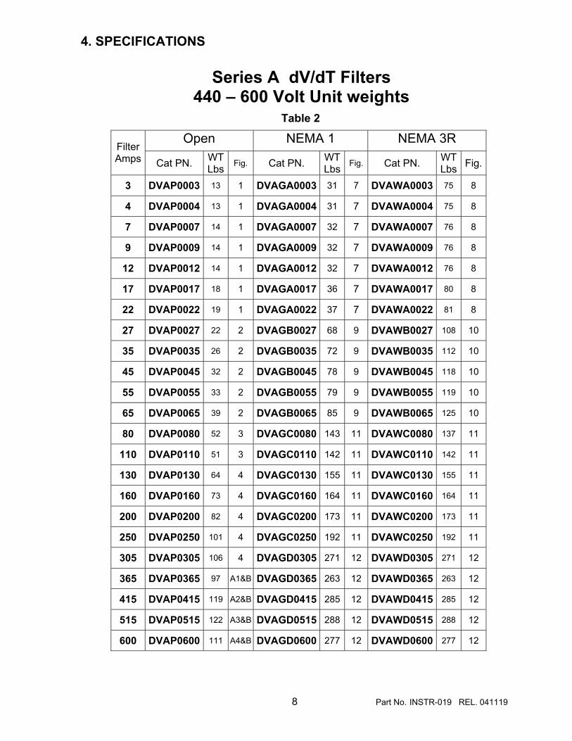
Series A dV/dT Filters 440 – 600 Volt Unit weights
Table 2
Open NEMA 1 NEMA 3R Filter Amps Cat PN. WT
Lbs Fig. Cat PN. WT Lbs Fig. Cat PN. WT
Lbs Fig.
3 DVAP0003 13 1 DVAGA0003 31 7 DVAWA0003 75 8
4 DVAP0004 13 1 DVAGA0004 31 7 DVAWA0004 75 8
7 DVAP0007 14 1 DVAGA0007 32 7 DVAWA0007 76 8
9 DVAP0009 14 1 DVAGA0009 32 7 DVAWA0009 76 8
12 DVAP0012 14 1 DVAGA0012 32 7 DVAWA0012 76 8
17 DVAP0017 18 1 DVAGA0017 36 7 DVAWA0017 80 8
22 DVAP0022 19 1 DVAGA0022 37 7 DVAWA0022 81 8
27 DVAP0027 22 2 DVAGB0027 68 9 DVAWB0027 108 10
35 DVAP0035 26 2 DVAGB0035 72 9 DVAWB0035 112 10
45 DVAP0045 32 2 DVAGB0045 78 9 DVAWB0045 118 10
55 DVAP0055 33 2 DVAGB0055 79 9 DVAWB0055 119 10
65 DVAP0065 39 2 DVAGB0065 85 9 DVAWB0065 125 10
80 DVAP0080 52 3 DVAGC0080 143 11 DVAWC0080 137 11
110 DVAP0110 51 3 DVAGC0110 142 11 DVAWC0110 142 11
130 DVAP0130 64 4 DVAGC0130 155 11 DVAWC0130 155 11
160 DVAP0160 73 4 DVAGC0160 164 11 DVAWC0160 164 11
200 DVAP0200 82 4 DVAGC0200 173 11 DVAWC0200 173 11
250 DVAP0250 101 4 DVAGC0250 192 11 DVAWC0250 192 11
305 DVAP0305 106 4 DVAGD0305 271 12 DVAWD0305 271 12
365 DVAP0365 97 A1&B DVAGD0365 263 12 DVAWD0365 263 12
415 DVAP0415 119 A2&B DVAGD0415 285 12 DVAWD0415 285 12
515 DVAP0515 122 A3&B DVAGD0515 288 12 DVAWD0515 288 12
600 DVAP0600 111 A4&B DVAGD0600 277 12 DVAWD0600 277 12

5. INSTALLATION INSTRUCTIONS
9 Part No. INSTR-019 REL. 041119
Filter Installation dV/dT filters are supplied in the following mechanical configurations:
Panel mounted assemblies
Floor mounted general purpose NEMA 1 & 3R cabinets
Panel mounted filters are designed for mounting in the vertical plane in the customer’s enclosure. Include the power dissipation of the filter along with all the other components located in the panel to determine the internal temperature rise and cooling requirements of the enclosure. An option NC temperature switch opens if the reactor exceeds 180 °C. Allow a minimum side clearance of four (4) inches and a vertical clearance of six (6) inches for proper heat dissipation and access within the enclosure. Panel mounted dV/dT filters generate heat and should be positioned away from heat sensitive components. Ensure that proper panel orientation is maintained keeping the capacitors away from reactor heat flow. Avoid locations where the filter would be subjected to excessive vibrations. Figures 1 – 4 contain open panel outline drawings for the various current ratings and show proper panel alignment. For filters above 305 amps refer to table 5 and Figure A & B for the dimensions of the separately mounted reactor and the PCB resistor assembly. A pre-wired cable harness with connector is supplied with these units. The PCB resistor assembly should be located a minimum of 4 inches away from the reactor in the lowest temperature regions of the enclosure – generally toward the bottom. Connect the motor and inverter leads to the reactor terminals to complete the filter wiring. See figure 13 page 24.
General purpose NEMA 1,2 and 3R enclosed filters are designed for floor mounting in an environment suitable for the enclosure type. Do not install in or near a corrosive environment. Avoid locations where the filter would be subjected to excessive vibrations. Allow a minimum side and back clearance of eight (8) inches and front clearance of thirty-six (32 inches for proper heat dissipation and access. Page 17 will direct you to the appropriate outline drawings shown in fig. 5 through fig 10.

5. INSTALLATION INSTRUCTIONS
10 Part No. INSTR-019 REL. 041119
Mechanical installation Open Panel 3 – 22 Amps
Fig. 1

5. INSTALLATION INSTRUCTIONS
11 Part No. INSTR-019 REL. 041119
Mechanical installation
Open Panel 27 – 65 Amps
Fig. 2
65 Amp shown

5. INSTALLATION INSTRUCTIONS
12 Part No. INSTR-019 REL. 041119
Mechanical installation
Open Panel 80 – 110 Amps Fig. 3
110 Amp Shown

5. INSTALLATION INSTRUCTIONS
13 Part No. INSTR-019 REL. 041119
Mechanical installation
Open Panel 130 - 305 Amps Fig. 4
305 Amp shown

5. INSTALLATION INSTRUCTIONS
14 Part No. INSTR-019 REL. 041119
dV/dT Filters rated 365 amps through 600 amps are constructed from a reactor and a PCB resistor assembly connected by a (supplied) 48 inch wire harness. These components are designed to be mounted vertically within an appropriate enclosure. The reactor generates heat and should be mounted away from components affected by heat and aligned to allow cooling air to flow through it. A filter showing correct reactor alignment and cooling is shown in figure 5. The PCB assembly should be located at least 4 inches from the reactor and in the lowest temperature regions of the enclosure – generally toward the bottom. An MCC wiring example is shown in Figure 6.
Table 5
FIG.A
FIG. B
DIMENSIONS Inches Filter Amps Figure A B C D E 365 A1 16.5 11.75 10.50 4.85 4.6 415 A2 16.5 12.00 11.25 5.12 4.6 515 A3 16.5 11.50 11.75 5.62 4.6 600 A4 16.5 11.25 12.25 6.12 4.6

5. INSTALLATION INSTRUCTIONS
15 Part No. INSTR-019 REL. 041119
Fig. 5
OPEN REACTOR & PCB ASSEMBLY
600 amp open reactor & PCB filter shown in customer provided enclosure.
NOTE: Maintain orientation as shown for proper component cooling.

5. INSTALLATION INSTRUCTIONS
16 Part No. INSTR-019 REL. 041119
Fig. 6
350Hp MCC using optional bay for dV/dT installation
Note: The above dv/dt filter example is shown with customer provided support hardware. Other installation variations are at the customer’s discretion as long as thermal guidelines are followed.

5. INSTALLATION INSTRUCTIONS
17 Part No. INSTR-019 REL. 041119
Enclosed Units Table 6
Enclosure Indicator Width Height Depth Cab Part
No. NEMA Type Figure
GA 13 13 13 Cab 13V NEMA 1 7 GB 17 24 18 Cab 17V NEMA 1 9 GC 24 30 24 Cab 20B NEMA 1 -2 11 GD 26.5 47 25 Cab 26C NEMA 1 -2 12 WA 12.5 24 18* Cab 12C NEMA 3R 8 WB 17.5 31 21* Cab 17C NEMA 3R 10 WC 20.5 31 21* Cab 20B NEMA 3R 11 WD 26.5 47 25* Cab 26C NEMA 3R 12
See table 2 on page 8 for enclosed weights
Table 7
General Purpose Cabinets 440 – 480 VAC Filter Current
Rating NEMA 1 NEMA 3R 3 CAB-13V CAB-12C 4 CAB-13V CAB-12C 7 CAB-13V CAB-12C 9 CAB-13V CAB-12C
12 CAB-13V CAB-12C 17 CAB-13V CAB-12C 22 CAB-13V CAB-12C 27 CAB-17V CAB-17C 35 CAB-17V CAB-17C 45 CAB-17V CAB-17C 55 CAB-17V CAB-17C 65 CAB-17V CAB-17C 80 CAB-20B CAB-20B
110 CAB-20B CAB-20B 130 CAB-20B CAB-20B 160 CAB-20B CAB-20B 200 CAB-20B CAB-20B 250 CAB-20B CAB-20B 305 CAB-26C CAB-26C 365 CAB-26C CAB-26C 415 CAB-26C CAB-26C 515 CAB-26C CAB-26C 600 CAB-26C CAB-26C
Mounting dimensions and outline drawings for filters mounted in NEMA 1, 3R Enclosures follow

5. INSTALLATION INSTRUCTIONS
18 Part No. INSTR-019 REL. 041119
Enclosed NEMA 1 units 3 – 22 Amps
Fig. 7 Cab 13V
22 Amp Shown

5. INSTALLATION INSTRUCTIONS
19 Part No. INSTR-019 REL. 041119
Enclosed 3R units 3 – 22 Amps
Fig. 8 Cab 12C
22 Amp Shown

5. INSTALLATION INSTRUCTIONS
20 Part No. INSTR-019 REL. 041119
Enclosed NEMA 1 units 27 – 65 Amps Fig. 9 Cab 17V
65 Amp Shown

5. INSTALLATION INSTRUCTIONS
21 Part No. INSTR-019 REL. 041119
Enclosed 3R units 27 – 65 Amps
Fig. 10 Cab 17C
65 Amp Shown

5. INSTALLATION INSTRUCTIONS
22 Part No. INSTR-019 REL. 041119
NEMA 1-2 & 3R units 80 – 250 Amps
Fig. 11 Cab 20B
250 Amp Shown

5. INSTALLATION INSTRUCTIONS
23 Part No. INSTR-019 REL. 041119
NEMA 1-2 & 3R units 305-600 Amps
Fig. 12 Cab 26C
600 Amp Shown

5. INSTALLATION INSTRUCTIONS
24 Part No. INSTR-019 REL. 041119
Wiring Connections
WARNING
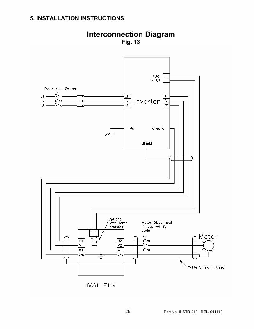
Input and output wiring to the filter should be performed by authorized personnel in accordance with NEC and all local electrical codes and regulations. Verify that the rating of the inverter is compatible with the inverter to which it is to be connected. Follow all detailed inverter manufacturer installation and safety instructions. Inverter and motor Cable selection / placement should be in accordance with the requirements of the NEC and all local electrical codes and regulations Typical filter interconnection diagrams that follow show wiring between the inverter, filter and motor. Refer to the inverter user manual for instructions on interconnecting the inverter and motor and the correct start-up procedures for the inverter. The optional over temperature switch wiring is also shown on figure13. The temperature switch is normally closed and will open when an internal reactor temperature of 180 °C is reached. The filter is designed for use with copper conductors with a minimum temperature rating of 75 degrees C. Table 8 lists the wire range and terminal torque requirements for the power input and output connections by horsepower rating. For panel mounted filters rated 365 amperes or more, the filter reactor is supplied un-mounted and capacitors and resistors are supplied as a pre-wired PCB assembly. A connector allows reactors and PCB to be separated for installation. Refer to figure 13 for the interconnection diagram.
The PCB assembly should be located in the lowest temperature regions of the enclosure - generally toward the bottom – the reactor assembly may be located in any region where the ambient temperature does not exceed 50 degrees C Use the cable recommended by the inverter manufacturer to connect the inverter to the filter and the filter to the motor. Make certain, that the selected cable size conforms to the requirements of the National Electric Code and all local codes. For open filters refer to Figures 1 through 4 for the location of Input, output, and ground connections. For enclosed filters, ground terminals will be clearly marked. Power wiring terminations are clearly marked on the reactor. Grounding The filter must always be grounded with a grounding conductor connected to ground terminals. For cable shield grounding follow the inverter manufactures recommendations. Fig 13 shows a typical shield ground connection. Optional Over Temperature Interlock The optional over temperature interlock can be used to turn off the inverter in the event it is setup to operate with a switching frequency outside of the range of the filter or an inverter malfunction. The interlock is a normally closed contact. Refer to table 9 for contact rating information and to the inverter user manual for interconnection information.
5. INSTALLATION INSTRUCTIONS
25 Part No. INSTR-019 REL. 041119
Interconnection Diagram Fig. 13

5. INSTALLATION INSTRUCTIONS
26 Part No. INSTR-019 REL. 041119
Terminal Wiring Specifications
Table 8
Filter
Rating(Amps) Terminals
Wire Range (AWG)
Terminal Torque (in-lbs)
3 22-14 16 4 22-14 16 7 22-14 16 9 22-14 16
12 22-5 16 17 22-5 16 22 22-5 16 27 22-5 16 35 22-5 16 45 18-4 20 55 18-4 20 65 6-4 & 2-0 50 80 6-4 & 2-0 50
110 3/0 75C 250 130 4/0 75C 250 160 3/0 90C 250 200 4/0 90C
250MCM 75C 325 250 400MCM 90C 375 305 600MCM
4/0 2X 90C 375 365 300MCM 2X 90C 375 415 350MCM 2X 90C 375 515 600MCM 2X 90C
300MCM 3X 90C 375 600 500MCM 3X 90C 375

5. INSTALLATION INSTRUCTIONS
27 Part No. INSTR-019 REL. 041119
OPTIONAL OVER TEMPERATURE INTERLOCK CONTACT RATINGS
Table 9
TYPE BI – METAL THERMAL SWITCH
CONTACT (NC) NORMALLY CLOSED
RATINGS
6A 120 VAC RESISTIVE 3A 240 VAC RESISTIVE 5A 120 VAC INDUCTIVE 2.5A 240 VAC INDUCTIVE
TEMPERATURE CONTACTS OPEN 180°C

6. FILTER DESCRIPTION
28 Part No. INSTR-019 REL. 041119
MTE Series A dV/dT filters are designed to protect AC motors from the damaging effects of long cable
runs between the inverter and motor. Depending on the turn-on
time of the power semiconductors used in an inverter and the size of the motor, cable lengths greater
than eight feet can result in motor peak voltages that exceed the rating
of the motor’s insulation system. (See: Effects of Cable Length
section. Chart 4 and table 9. pg 29) Typical applications include submersible pumps, HVAC equipment and process automation lines. Motors rated 100 HP and below and standard NEMA B motors are prone to failure as a result of high voltage spikes and will benefit from dV/dT filtering. The dV/dT filter is a passive fourth order device that reduces transmission line effects of motor cables. It accomplishes this by dampening the rate of voltage increase and minimizes the peak voltage that occurs at the motor terminals. See performance chart 1 pg. 5 to view actual results. Series A dV/dT filters are designed for use with inverters operated at switching frequencies between 900 Hz and 8 kHz. The filter is guaranteed to reduce the maximum peak motor voltage (150% of inverter bus voltage) with 1,000 feet of cable between the filter and the motor. In specific applications, the filter has provided excellent performance with cable runs up to 3,000 feet. The dV/dT filter has a 3% insertion impedance which ensures motor torque is not affected by added voltage drops from the filter.
Series A dV/dT filters are available as open panel mount and with enclosed ratings including NEMA 1 ,2 and NEMA 3R. These filters have been designed to meet motor current requirements based on NEC motor current ratings. For application using motors that exceed NEC current ratings use the next larger filter. Apply the appropriate altitude current de-rating curves shown on chart 2. Filters for motors that will be operated above 60 Hz should be selected based on the chart 3 inverter frequency current de-rating curve shown on page 6. Systems with multiple motors powered from a single inverter form a complex inverter load. The dV/dT filter works best when applied to each cable / motor. For multi motor applications consider using a single MTE sine wave filter for all motors. In this case the filter should be sized for the total motor load. Consult MTE applications for help in determining the best solution. The dV/dT filter is designed to protect a single cable/ motor load. Do not connect other high current electrical devices to the output of the dV/dT filter.

6. FILTER DESCRIPTION
29 Part No. INSTR-019 REL. 041119
Effects of Cable Length Chart 4
When to add dV/dT protection
Table 9
Rise Time (microseconds)
Critical Lead Length (meters)
Critical Lead Length (feet)
2.00 100 328
1.0 50 164
0.50 25 82
0.10 5 16
0.05 2.5 8

6. FILTER DESCRIPTION
30 Part No. INSTR-019 REL. 041119
Typical filter Schematic Diagram Fig. 14
Typical internal filter wiring
Fig. 15

7. START - UP
31 Part No. INSTR-019 REL. 041119
Safety Precautions Before startup, observe the following warnings and instructions:
WARNING Internal components of the filter are at line potential when the filter is connected to the drive This voltage is extremely dangerous and may cause death or severe injury if you come in contact with it. WARNING After disconnecting the utility power, wait at least 5 minutes before doing any work on the filter connections. After removing power, allow at least five minutes to elapse and verify that the capacitors have discharged to a safe level before contacting internal components. Connect a DC voltmeter across the capacitor terminals. Start with the meter on the highest scale and progressively switch to a lower scale as the indicated voltage falls below the maximum value of the scale used. Sequence of Operation
1. Read and follow safety precautions. Including those of drive manufactures.
2. After installation, ensure that: • All filter ground terminals are connected to
ground. • Power wiring to the utility, inverter, filter and
motor is in accordance with the installation and connection instructions in Chapter 5.
3. Check that moisture has not condensed on
the filter components. If moisture is present, do not proceed with startup until the moisture has been removed.
WARNING
Use extreme caution to avoid contact with line voltage when checking for power. INJURY OR DEATH MAY RESULT IF SAFETY PRECAUTIONS ARE NOT OBSERVED.
4. Refer to the inverter user manual for the
inverter startup procedure. Observe all safety instructions in the inverter user manual.
5. Disconnect filter output terminals from
the motor.
6. Set the inverter switching frequency between 2 kHz and 8 kHz. Refer to the inverter user manual.
CAUTION
Damage to the filter may occur if the inverter frequency is not set between 2 kHz and 8 KHz.
7. Turn the inverter ON
8. Confirm that inverter voltage is present at the input terminals (U1, V1, W1) of the filter.
9. Confirm that inverter voltage is present at
the output terminals (U2, V2, W2) of the filter.
10. Disconnect the inverter from the AC Line
and wait 5 minutes.
11. Connect the filter output to the motor.
12. Refer to the inverter user manual for the motor startup procedure.
WARNING
INJURY OR DEATH MAY RESULT IF THE INVERTER SAFETY PRECAUTIONS ARE NOT OBSERVED
CAUTION
Damage to equipment or serious injury
may occur if the inverter startup procedures are not observed..

8. TROUBLESHOOTING
32 Part No. INSTR-019 REL. 041119
WARNING When properly installed, this equipment has been designed to provide maximum safety for operating personnel. However, hazardous voltages and elevated temperatures exist within the confines of the enclosure. Servicing should therefore be performed by qualified personnel only and in accordance with OSHA Regulations. To aid in troubleshooting use the diagrams is shown on page 29. A list of potential problems and solutions are listed below.
WARNING High voltage is used in the operation of this filter. Use Extreme caution to avoid contact with high voltage when operating, installing or repairing this filter. INJURY OR DEATH MAY RESULT IF SAFETY PRECAUTIONS ARE NOT OBSERVED. After removing power, allow at least five minutes to elapse and verify that the capacitors have discharged to a safe level before contacting internal components. Connect a DC voltmeter across the capacitor terminals or terminals U1,V1or V1, W1 Start with the meter on the highest scale and progressively switch to a lower scale as the indicated voltage falls below the maximum value of the scale used.

8. TROUBLESHOOTING
33 Part No. INSTR-019 REL. 041119
PROBLEM: Voltage is not present at the filter Input terminals.
Possible cause: Power to the inverter is turned off or shut down.
Solution: Turn power on, check inverter errors.
Possible cause: One or more external line fuses are blown.
Solution: Verify the continuity of line fuses in all phases. Replace as necessary.
Possible cause: Damage to inverter - dV/dT interconnect cables
Solution: Replace damaged cable.
Possible cause: Inverter setup parameters are incorrect
Solution: Verify motor current, voltage and shutdown parameters are valid
PROBLEM: dV/dT filter runs Hot
Possible cause: Normal operation reactor and resistors are > 100 °C
Solution: Caution parts are very hot and may cause burns. Follow installation guidelines for clearances and check for adequate air flow.
Possible cause: Motor coil damage windings shorted
Solution: Replace motor inspect wiring
Possible cause: Heat buildup within enclosure
Solution: Provide clearance and venting for filter components