institutional repository - research portal d p t ... · chapter 1 introduction peer-to-peer (p2p)...
TRANSCRIPT
Institutional Repository - Research PortalDépôt Institutionnel - Portail de la Recherche
THESIS / THÈSE
Author(s) - Auteur(s) :
Supervisor - Co-Supervisor / Promoteur - Co-Promoteur :
Publication date - Date de publication :
Permanent link - Permalien :
Rights / License - Licence de droit d’auteur :
Bibliothèque Universitaire Moretus Plantin
researchportal.unamur.beUniversity of Namur
MASTER IN COMPUTER SCIENCE
Analysis and prototyping of the IETF RELOAD protocol onto a Java application server
Roly, Antoine
Award date:2009
Link to publication
General rightsCopyright and moral rights for the publications made accessible in the public portal are retained by the authors and/or other copyright ownersand it is a condition of accessing publications that users recognise and abide by the legal requirements associated with these rights.
• Users may download and print one copy of any publication from the public portal for the purpose of private study or research. • You may not further distribute the material or use it for any profit-making activity or commercial gain • You may freely distribute the URL identifying the publication in the public portal ?
Take down policyIf you believe that this document breaches copyright please contact us providing details, and we will remove access to the work immediatelyand investigate your claim.
Download date: 22. Jun. 2020
Facultés Universitaires Notre-Dame de la Paix de Namur
Faculté d’informatique
Année académique 2008-2009
Analysis and prototypingof the IETF RELOAD protocolonto a Java application server
Antoine Roly
Mémoire présenté en vue de l’obtention du grade de master en informatique


Abstract
Facing the rise of Peer-to-Peer (P2P) networks and applications in the last years, many have
seen a need for standardization. Indeed, a lot of proprietary protocols currently coexist, each
one using its own specifications, messages, algorithms, etc. To sort things out, the Internet En-
gineering Task Force has created the Peer-to-Peer Session Initiation Protocol (P2PSIP) working
group in 2007, in order to develop an open, standard, generic P2P protocol and provide a generic
way to manage a Distributed Hash Table (DHT). This master thesis presents and criticizes the
REsource LOcation And Discovery (RELOAD) protocol and a prototype of this protocol im-
plemented on an IP Multimedia Subsystem (IMS) service platform.
Keywords:: RELOAD, Distributed Hash Table
Résumé
Face à l’émergence de réseaux et d’applications Peer-to-Peer (P2P) ces dernières années,
un besoin de standardisation s’est fait largement ressentir. En effet, beaucoup de protocoles
propriétaires coexistent actuellement, chacun utilisant ses propres spécifications, messages, al-
gorithms, etc. Pour mettre un terme à cette situation, l’Internet Engineering Task Force a créé
en 2007 le working group Peer-to-Peer Session Initiation Protocol (P2PSIP), afin de développer
un protocole P2P générique, standard et ouvert, et fournir une manière générique de gérer une
table de hachage distribuée. Ce mémoire présente et critique le protocole REsource LOcation
And Discovery (RELOAD) et un prototype de ce protocole implémenté sur une plateforme de
services IP Multimedia Subsystem (IMS).
Mots clés: RELOAD, Table de hachage distribuée

Acknowledgments
This master thesis could not have been written without the help of various people.
I would like to thank the Alcatel-Lucent Service Creation Environment team to have cor-
dially received me during my internship. In particular, I would like to thank Thomas Froment,
my internship supervisor, for his advices and the time spent on my work, Dimitri Tombroff,
Pierre De Rop and Arjun Panday for their help during the implementation of the RELOAD
prototype.
I also want to acknowledge my thesis supervisor: Professor Laurent Schumacher for his
feedbacks as well as his many corrections and suggestions, and Reddy Emply for his rereadings
and corrections.
Finally, thanks to my family for their continuous support during my long and complicated
studies course.

Contents
1 Introduction 1
2 Peer-to-peer: overview 3
3 RELOAD protocol 7
3.1 Presentation of the protocol . . . . . . . . . . . . . . . . . . . . . . . . . . . . . 7
3.2 Terminology . . . . . . . . . . . . . . . . . . . . . . . . . . . . . . . . . . . . . . 8
3.3 Architecture . . . . . . . . . . . . . . . . . . . . . . . . . . . . . . . . . . . . . . 10
3.4 Chord algorithm . . . . . . . . . . . . . . . . . . . . . . . . . . . . . . . . . . . 13
3.5 Obtaining of a certificate . . . . . . . . . . . . . . . . . . . . . . . . . . . . . . . 13
3.6 Interpretation/Understanding Draft issues . . . . . . . . . . . . . . . . . . . . . 14
3.6.1 Handling unstructured overlays . . . . . . . . . . . . . . . . . . . . . . . 15
3.6.2 Client issues . . . . . . . . . . . . . . . . . . . . . . . . . . . . . . . . . . 16
3.6.3 Enhanced Client concept . . . . . . . . . . . . . . . . . . . . . . . . . . . 18
3.6.4 Variable length structure . . . . . . . . . . . . . . . . . . . . . . . . . . . 20
3.6.5 Unknown Kind of Data . . . . . . . . . . . . . . . . . . . . . . . . . . . 21
3.6.6 Unknown options . . . . . . . . . . . . . . . . . . . . . . . . . . . . . . . 21
3.6.7 Generation counter . . . . . . . . . . . . . . . . . . . . . . . . . . . . . . 22
3.6.8 Detecting partitioning . . . . . . . . . . . . . . . . . . . . . . . . . . . . 22
3.6.9 Unreliable links . . . . . . . . . . . . . . . . . . . . . . . . . . . . . . . . 23
3.6.10 ICE-TCP and ICE-Lite outdated . . . . . . . . . . . . . . . . . . . . . . 25
3.6.11 Maximum size of a stored value . . . . . . . . . . . . . . . . . . . . . . . 25
3.6.12 Handling failures . . . . . . . . . . . . . . . . . . . . . . . . . . . . . . . 25
3.7 Related works . . . . . . . . . . . . . . . . . . . . . . . . . . . . . . . . . . . . . 25
3.7.1 Overlay diagnostics . . . . . . . . . . . . . . . . . . . . . . . . . . . . . . 26
3.7.2 Location and Discovery of Subsets of Resources . . . . . . . . . . . . . . 26
3.7.3 Pointers for Peer-to-Peer Overlay Networks, Nodes, or Resources . . . . 27
3.7.4 Hierarchical P2PSIP Overlay . . . . . . . . . . . . . . . . . . . . . . . . 27
vii

Master Thesis CONTENTS
3.7.5 Traffic localization for RELOAD . . . . . . . . . . . . . . . . . . . . . . 27
3.7.6 Self-tuning Distributed Hash Table for RELOAD . . . . . . . . . . . . . 28
3.7.7 A Load Balancing Mechanism for RELOAD . . . . . . . . . . . . . . . 28
3.7.8 Topology Plug in for RELOAD . . . . . . . . . . . . . . . . . . . . . . . 29
3.7.9 Deterministic Replication for RELOAD . . . . . . . . . . . . . . . . . . 29
3.7.10 A P2PSIP Client Routing for RELOAD . . . . . . . . . . . . . . . . . . 30
3.7.11 P2PSIP Security Requirements . . . . . . . . . . . . . . . . . . . . . . . 30
3.7.12 Threat Analysis for Peer-to-Peer Overlay Networks . . . . . . . . . . . . 31
3.8 Configuration of a RELOAD node . . . . . . . . . . . . . . . . . . . . . . . . . 31
4 Usages of RELOAD 35
4.1 SIP usage of RELOAD . . . . . . . . . . . . . . . . . . . . . . . . . . . . . . . 35
4.2 Other uses . . . . . . . . . . . . . . . . . . . . . . . . . . . . . . . . . . . . . . . 37
4.2.1 Domain Name System . . . . . . . . . . . . . . . . . . . . . . . . . . . . 38
4.2.2 Jabber/XMPP . . . . . . . . . . . . . . . . . . . . . . . . . . . . . . . . 40
4.2.3 Content Delivery Network . . . . . . . . . . . . . . . . . . . . . . . . . . 43
5 Environment 45
5.1 The A5350 proxy platform . . . . . . . . . . . . . . . . . . . . . . . . . . . . . . 45
5.2 The Service Creation Environment . . . . . . . . . . . . . . . . . . . . . . . . . 46
5.3 OSGi framework . . . . . . . . . . . . . . . . . . . . . . . . . . . . . . . . . . . 47
5.3.1 The OSGi Alliance . . . . . . . . . . . . . . . . . . . . . . . . . . . . . . 47
5.3.2 The OSGi architecture . . . . . . . . . . . . . . . . . . . . . . . . . . . . 47
5.3.3 Presentation of the OSGi Technology . . . . . . . . . . . . . . . . . . . . 49
5.3.4 Interest of using OSGi Framework . . . . . . . . . . . . . . . . . . . . . 50
6 Implementation 53
6.1 Limitations, shortcuts, . . . . . . . . . . . . . . . . . . . . . . . . . . . . . . . . . 54
6.2 Interests and advantages of the architecture . . . . . . . . . . . . . . . . . . . . 54
6.2.1 RELOAD container . . . . . . . . . . . . . . . . . . . . . . . . . . . . . 54
6.2.2 RELOAD application . . . . . . . . . . . . . . . . . . . . . . . . . . . . 56
6.3 Implementation issues . . . . . . . . . . . . . . . . . . . . . . . . . . . . . . . . 57
6.3.1 C-like structure . . . . . . . . . . . . . . . . . . . . . . . . . . . . . . . . 58
6.3.2 NAT traversal . . . . . . . . . . . . . . . . . . . . . . . . . . . . . . . . . 58
6.3.3 Unsigned integers . . . . . . . . . . . . . . . . . . . . . . . . . . . . . . . 59
6.3.4 Binary protocol . . . . . . . . . . . . . . . . . . . . . . . . . . . . . . . . 60
6.4 Use related to the A5350 proxy platform . . . . . . . . . . . . . . . . . . . . . . 60
viii

Master Thesis CONTENTS
7 The Open Multimedia Platform framework 61
7.1 Presentation and background . . . . . . . . . . . . . . . . . . . . . . . . . . . . 61
7.2 Architecture, characteristics, layers, . . . . . . . . . . . . . . . . . . . . . . . . . 63
7.2.1 The application server . . . . . . . . . . . . . . . . . . . . . . . . . . . . 64
7.2.2 Middleware . . . . . . . . . . . . . . . . . . . . . . . . . . . . . . . . . . 65
7.2.3 OAM . . . . . . . . . . . . . . . . . . . . . . . . . . . . . . . . . . . . . 65
7.2.4 Hardware architecture . . . . . . . . . . . . . . . . . . . . . . . . . . . . 65
7.2.5 Reuse of components . . . . . . . . . . . . . . . . . . . . . . . . . . . . . 66
7.3 Comparison between OMP framework and OSGi . . . . . . . . . . . . . . . . . 66
7.3.1 Generalities . . . . . . . . . . . . . . . . . . . . . . . . . . . . . . . . . . 66
7.3.2 Reuse of components . . . . . . . . . . . . . . . . . . . . . . . . . . . . . 67
7.3.3 OAM . . . . . . . . . . . . . . . . . . . . . . . . . . . . . . . . . . . . . 67
7.3.4 Structure of applications . . . . . . . . . . . . . . . . . . . . . . . . . . . 68
7.3.5 Conclusion . . . . . . . . . . . . . . . . . . . . . . . . . . . . . . . . . . 69
8 Conclusion 71
Bibliography 72
A reload.xml file i
B sip.xml file iii
ix

List of Figures
3.1 RELOAD architecture . . . . . . . . . . . . . . . . . . . . . . . . . . . . . . . . 10
3.2 A RELOAD Chord ring . . . . . . . . . . . . . . . . . . . . . . . . . . . . . . . 14
3.3 Overlay with a client connected to its AP . . . . . . . . . . . . . . . . . . . . . 16
3.4 eClient, DAP and OAP . . . . . . . . . . . . . . . . . . . . . . . . . . . . . . . 19
3.5 Detecting partitioning . . . . . . . . . . . . . . . . . . . . . . . . . . . . . . . . 24
4.1 SIP usage of RELOAD . . . . . . . . . . . . . . . . . . . . . . . . . . . . . . . 37
4.2 new SIP usage of RELOAD . . . . . . . . . . . . . . . . . . . . . . . . . . . . . 38
4.3 Classical XMPP network . . . . . . . . . . . . . . . . . . . . . . . . . . . . . . . 41
4.4 XMPP network using RELOAD overlay . . . . . . . . . . . . . . . . . . . . . . 41
4.5 Content Sharing Usage for RELOAD . . . . . . . . . . . . . . . . . . . . . . . 43
5.1 ASR layers . . . . . . . . . . . . . . . . . . . . . . . . . . . . . . . . . . . . . . 45
5.2 Application’s general architecture onto the ASR . . . . . . . . . . . . . . . . . . 46
5.3 Layers of the OSGi Framework . . . . . . . . . . . . . . . . . . . . . . . . . . . 47
5.4 OSGi framework layers . . . . . . . . . . . . . . . . . . . . . . . . . . . . . . . . 50
6.1 Sample of code - doXXX() pattern - doJoin() . . . . . . . . . . . . . . . . . . 57
6.2 Implementation with a "servlet-like" container . . . . . . . . . . . . . . . . . . . 58
6.3 Sequence diagram representing messages exchange. . . . . . . . . . . . . . . . . 59
7.1 Layers of the Open Multimedia Platform framework (OMP) architecture . . . . 63
7.2 Components of the Open Multimedia Platform framework (OMP) architecture 64
7.3 ASR Web Admin - Deploying applications . . . . . . . . . . . . . . . . . . . . . 68
xi


List of Tables
2.1 Classification of peer-to-peer content distribution systems [1] . . . . . . . . . . . 4
6.1 Comparison of the RELOAD message’s header. . . . . . . . . . . . . . . . . . . 55
xiii


Table of Acronyms
AIMD Additive increase/multiplicative decrease
AMF Availability Management Framework
AOR Address-of-Record
API Application Programming Interface
ASR Application Server Runtime
CDC Connected Device Configuration
CDN Content Delivery Network
CKPT Checkpoint service
CLDC Connected Limited Device Configuration
CRL Certificate Revocation List
CSC Content Sharing Client
DHT Distributed Hash Table
DNS Domain Name System
DTLS Datagram Transport Layer Security
EJB Enterprise Java Beans
HTTP HyperText Transfer Protocol
HTTPS HyperText Transfer Protocol Secure
IAS IMS Application Server
ICE Interactive Connectivity Establishment
IETF Internet Engineering Task Force
IMM Information model management
IMS IP Multimedia Subsystem
IP Internet Protocol
J2SE Java 2 Standard Edition
JAR Java Archives
JEE Java Platform Enterprise Edition
JMX Java Management Extensions
continued on next page
Master Thesis LIST OF TABLES
MIDP Mobile Information Device Profile
NAT Network Address Translation
NTF Notification service
OAM Operations, administration and maintenance
OAP Overlay Attachment Point
OMP Open Multimedia Platform
OSGi Open Services Gateway initiative
P2P Peer-to-Peer
RELOAD REsource LOcation And Discovery
RFC Requests for Comments
RTO Retransmission TimeOut
SAF Service Availability Forum
SCE Service Creation Environment
SGCS Sun Glassfish Communication Server
SIP Session Initiation Protocol
SNMP Simple Network Management Protocol
STUN Simple Traversal of UDP through NATs
TCP Transmission Control Protocol
TLS Transport Layer Security
TFRC TCP Friendly Rate Control
TFRC-SP TCP Friendly Rate Control, The Small-Packet Variant
TURN Traversal Using Relay NAT
UA User Agent
UDP User Datagram Protocol
URI Unified Resource Identifier
VIP Virtual Internet Protocol
WG Working Group
XML eXtensible Markup Language
XMPP eXtensible Messaging and Presence Protocol
xvi


Chapter 1
Introduction
Peer-to-peer (P2P) techniques are more and more common in every aspect of computer sci-
ence. Everybody has heard about file sharing on the Internet, but many other applications
are possible, like P2P voice over Internet Protocol (IP) applications (Skype for instance), me-
dia streaming, content distribution, etc. These techniques are also used to provide anonymity
(Freenet and Tor) and security to users.
The current situation is quite a mess as many applications use their own protocol and a lot
of them are proprietary. This brings many problems in term of compliance and interoperability.
Moreover, with the increased use of Network Address Translation (NAT) techniques (due to
lack of IPv4 addresses among other reasons) and with security problems found on the Internet,
the development of an open, secure, generic P2P protocol which could be used in a lot of P2P
applications has become essential.
Established in March 2007, the Peer-to-Peer Session Initiation Protocol Working Group
(P2PSIP WG) task was (among others) to propose a standard P2PSIP protocol:
• to be used between P2PSIP overlay peers, sometimes behind NATs
• defining how the P2PSIP peers provide user and resource location with no (or minimal)
centralized server
• using the Distributed Hash Table (DHT) algorithm.
This protocol was named RELOAD for REsource Location And Discovery.
P2P techniques bring a lot of advantages like scalability, failure tolerance, etc. In most cases,
they are used to create and maintain an overlay network. With the overlay, peers (or clients)
store and retrieve data without the need of a central server. The overlay can, for instance,
replace a SIP proxy and/or a registrar. With the P2P algorithm, data could be fetched in a
efficient way, duplicated, etc. But, at this time, every application uses its own protocol and
1
Master Thesis CHAPTER 1. INTRODUCTION
technique, resulting in a specification, maintenance and interface nightmare.. As a result, the
Internet Engineering Task Force (IETF) decided to develop a generic P2P signaling protocol
providing a generic way of dealing with a P2P overlay, manage admissions or leaves of nodes,
store and retrieve data into the overlay, route messages, etc.
This thesis is based on my internship accomplished between September 2008 and January
2009 at Alcatel-Lucent. The goal was to analyze and develop a prototype of the in-development
IETF RELOAD protocol, and deploy the prototype to a Java application server. Final aim of
the work was to identify all the advantages such techniques could bring into a specific product.
There will be two main parts in this thesis.
1.The RELOAD protocol itself. It will be presented and criticized, both from a logical (the
algorithm itself, with the management of the DHT) and a technical (messages, structure . . . )
point of view.
2. After a short presentation of the working environment, a critique of an implementation
of the RELOAD draft (including choices of implementation techniques, pros and cons, pitfalls,
etc.).
Finally, the study of the Open Multimedia Platform (OMP) framework and the comparison
between the Open Services Gateway initiative (OSGi) framework used on the development
platform and this one will be presented.
2
Chapter 2
Peer-to-peer: overview
Before defining and presenting the RELOAD protocol, it would be interesting to give a brief
overview of the already existing protocols for P2P applications. There are a lot of protocols and
software components for P2P applications. Some are used by only one software application,
others are used by multiples ones. Here is a short list of well-known protocols:
• Ares
• Bittorrent
• Direct Connect
• eDonkey
• Fasttrack
• Gnutella
• MANOLITO/MP2PN
• OpenNAP
To give a precise description of the working of these protocols would be useless, but a short
presentation of the main architecture of P2P networks, critical algorithms, etc. could help
understanding of the current situation in the P2P world.
The main differences between protocols (beyond syntax and structure of messages) are, in
one hand, the overlay network centralization, with three main categories:
• "purely decentralized architecture: All nodes in the network perform exactly the
same tasks, acting both as servers and clients, with no central coordination of their activ-
ities. The nodes of such networks are often termed "servents" (SERVers + clieENTS).
3
Master Thesis CHAPTER 2. PEER-TO-PEER: OVERVIEW
• partially centralized architecture: The basis is the same as with purely decentralized
systems. Some of the nodes, however, assume a more important role, acting as local central
indexes for files shared by local peers. The way in which these supernodes are assigned
their role by the network varies among different systems. It is important, however, to
note that these supernodes do not constitute single points of failure for a peer-to-peer
network, since they are dynamically assigned. If they fail, the network will automatically
take action to replace them with others.
• hybrid decentralized architecture: In these systems, there is a central server facili-
tating the interaction between peers by maintaining directories of meta-data describing
the shared files stored by the peer nodes. Although the end-to-end interaction and file
exchanges may take place directly between two peer nodes, the central servers facilitate
this interaction by performing the lookups and identifying the nodes storing the files.
The terms "peer-through-peer" or "broker mediated" are sometimes used to refer to such
systems.
On the other hand, the network structure can be either:
• unstructured: The placement of content (files) is completely unrelated to the overlay
topology.
• structured: In structured networks, the overlay topology is tightly controlled and files
(or pointers to them) are placed at precisely specified locations"[1]
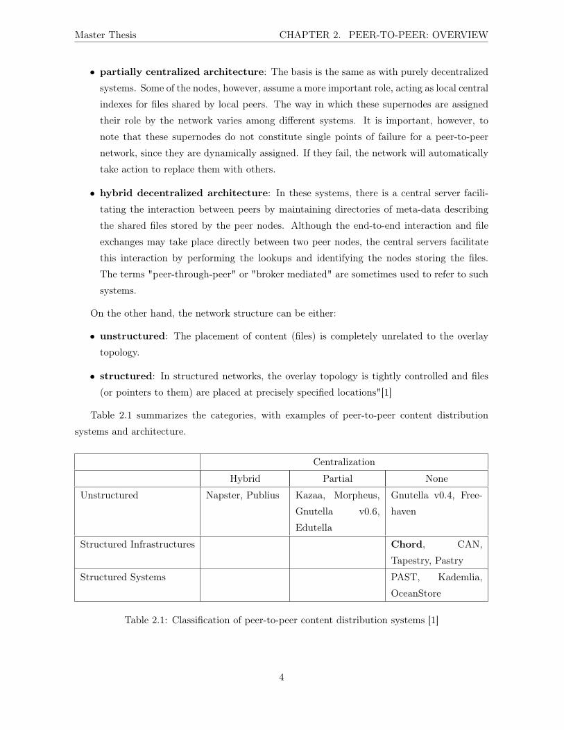
Table 2.1 summarizes the categories, with examples of peer-to-peer content distribution
systems and architecture.
Centralization
Hybrid Partial None
Unstructured Napster, Publius Kazaa, Morpheus,
Gnutella v0.6,
Edutella
Gnutella v0.4, Free-
haven
Structured Infrastructures Chord, CAN,
Tapestry, Pastry
Structured Systems PAST, Kademlia,
OceanStore
Table 2.1: Classification of peer-to-peer content distribution systems [1]
4

Master Thesis CHAPTER 2. PEER-TO-PEER: OVERVIEW
Chord is the overlay algorithm mandatory to implement in the RELOAD protocol, but other
algorithms could be used to manage the DHT (in this case, these protocols will probably be in
the same case as Chord) or to set up a different overlay network architecture (an unstructured
overlay network with no centralization seems possible, with Gnutella for example). For more
information about the possible network overlay architectures, see Section 3.6.1.
5

Chapter 3
RELOAD protocol
In this chapter, the RELOAD protocol will be presented and criticized, both from a technical
(structure, messages, . . . ) and a logical point of view (the DHT algorithm, . . . ).
This work is based on the current draft version, version 03, July 2009. The draft can be
found at the address http://tools.ietf.org/html/draft-ietf-p2psip-base.
3.1 Presentation of the protocol
"REsource LOcation And Discovery (RELOAD ) is a peer-to-peer (P2P) signaling protocol
for use on the Internet. It provides a generic, self-organizing overlay network service, allowing
nodes to efficiently route messages to other nodes and to efficiently store and retrieve data in
the overlay. RELOAD provides several features that are critical for a successful P2P protocol
for the Internet:
Security Framework: A P2P network will often be established among a set of peers that
do not trust each other. RELOAD leverages a central enrollment server to provide credentials
for each peer which can then be used to authenticate each operation. This greatly reduces the
possible attack exposure.
Usage Model: RELOAD is designed to support a variety of applications, including P2P
multimedia communications with the Session Initiation Protocol. RELOAD allows the defini-
tion of new application usages, each of which can define its own data types, along with the
rules for their use. This allows RELOAD to be used with new applications through a simple
documentation process supplying the details for each application.
NAT Traversal: RELOAD is designed to function in environments where many if not most
of the nodes are behind NATs or firewalls. Operations for NAT traversal are part of the base
7
Master Thesis CHAPTER 3. RELOAD PROTOCOL
design, including using Interactive Connectivity Establishment (ICE) to establish new RELOAD
or application protocol connections.
High Performance Routing: The very nature of overlay algorithms introduces a require-
ment that peers participating in the P2P network route requests on behalf of other peers in
the network. This introduces a load on those other peers, in the form of bandwidth and pro-
cessing power. RELOAD has been defined with a simple, lightweight forwarding header, thus
minimizing the amount of effort required by intermediate peers.
Pluggable Overlay Algorithms: RELOAD has been designed with an abstract interface
to the overlay layer to simplify implementing a variety of structured (DHT) and unstructured
overlay algorithms. This specification also defines how RELOAD is used with Chord, which is
mandatory to implement. Specifying a default "must implement" overlay algorithm will allow
interoperability, while the extensibility allows selection of overlay algorithms optimized for a
particular application.
These properties were designed specifically to meet the requirements for a P2P protocol to
support SIP. RELOAD is not limited to usage by SIP and could serve as a tool for supporting
other P2P applications with similar needs".[2]
3.2 Terminology
DHT: "A distributed hash table. A DHT is an abstract hash table service realized by storing
the contents of the hash table across a set of peers.
Overlay Algorithm: An overlay algorithm defines the rules for determining which peers in
an overlay store a particular piece of data and for determining a topology of interconnections
amongst peers in order to find a piece of data.
Overlay Instance: A specific overlay algorithm and the collection of peers that are collab-
orating to provide read and write access to it. There can be any number of overlay instances
running in an IP network at a time, and each operates in isolation of the others.
Peer: A host that is participating in the overlay. Peers are responsible for holding some
portion of the data that has been stored in the overlay and also route messages on behalf of
other hosts as required by the Overlay Algorithm.
8
Master Thesis CHAPTER 3. RELOAD PROTOCOL
Client: A host that is able to store data in and retrieve data from the overlay but which is
not participating in routing or data storage for the overlay.
Node: The term "Node" refers to a host that may be either a Peer or a Client. Because
RELOAD uses the same protocol for both clients and peers, much of the RELOAD related text
applies equally to both.
Node-ID: A 128-bit value that uniquely identifies a node. Node-IDs 0 and 2128 - 1 are
reserved and are invalid Node-IDs. A value of zero is not used in the wire protocol but can be
used to indicate an invalid node in implementations and Application Programming Interfaces
(APIs). The Node-ID of 2128 is used on the wire protocol as a wildcard.
Resource: An object or group of objects associated with a string identifier.
Resource Name: The potentially human readable name by which a resource is identified. In
unstructured P2P networks, the resource name is sometimes used directly as a Resource-ID. In
structured P2P networks the resource name is typically mapped into a Resource-ID by using
the string as the input to hash function. A SIP resource, for example, is often identified by its
Address-Of-Record (AOR) which is an example of a Resource Name.
Resource-ID: A value that identifies some resources and which is used as a key for storing
and retrieving the resource. Often this is not human friendly/readable. One way to gener-
ate a Resource-ID is by applying a mapping function to some other unique name (e.g., user
name or service name) for the resource. The Resource-ID is used by the distributed database
algorithm to determine the peer or peers that are responsible for storing the data for the over-
lay. In structured P2P networks, Resource-IDs are generally fixed length and are formed by
hashing the resource name. In unstructured networks, resource names may be used directly as
Resource-IDs and may have variable length.
Connection Table: The set of peers to which a node is directly connected. This includes
nodes with which Attach handshakes have been done but which have not sent any Updates.
Routing Table: The set of peers which a peer can use to route overlay messages. In general,
these peers will all be on the connection table but not vice versa, because some peers will have
Attached but not sent Updates. Peers may send messages directly to peers that are in the
connection table but may only route messages to other peers through peers that are in the
routing table.
9

Master Thesis CHAPTER 3. RELOAD PROTOCOL
Destination List: A list of IDs through which a message is to be routed. A single Node-ID
is a trivial form of destination list.
Usage: A usage is an application that wishes to use the overlay for some purpose. Each
application wishing to use the overlay defines a set of data kinds that it wishes to use. The SIP
usage defines the location data kind."[2]
Churn: "The arrival and departure of peers to and from the overlay, which changes the peer
population of the overlay".[3]
3.3 Architecture
RELOAD is an overlay network, and can be divided in several components, as depicted in the
following picture.
Figure 3.1: RELOAD architecture
10
Master Thesis CHAPTER 3. RELOAD PROTOCOL
The major components of RELOAD architecture are:
Usage Layer : "Each application defines a RELOAD usage; a set of data kinds and behaviors
which describe how to use the services provided by RELOAD . These usages all talk to RELOAD
through a common Message Transport API.
Message Transport : Handles the end-to-end reliability, manages request state for the us-
ages, and forwards Store and Fetch operations to the Storage component. Delivers message
responses to the component initiating the request.
Storage : The Storage component is responsible for processing messages relating to the stor-
age and retrieval of data. It talks directly to the Topology Plugin to manage data replication
and migration, and it talks to the Message Transport to send and receive messages. This
component can use these messages:
• Store: this message is sent by a node for storing data in the overlay.
• Fetch: the Fetch message retrieves one or more elements stored in the overlay.
• Stat: this request is used to get meta-data for a stored element without retrieving the
element itself.
• Find: this message can be used to explore the overlay, or knowing the responsible peer
for certain data.
For these messages, both requests and responses are defined.
Topology Plugin : The Topology Plugin is responsible for implementing the specific overlay
algorithm being used. It uses the Message Transport component to send and receive overlay
management messages, to the Storage component to manage data replication, and directly to the
Forwarding Layer to control hop-by-hop message forwarding. This component closely parallels
conventional routing algorithms, but is more tightly coupled to the Forwarding Layer because
there is no single "routing table" equivalent used by all overlay algorithms. The messages used
by this plugin are:
• Join: this message is sent by a new peer to join the overlay. It is sent to the responsible
peer and warn him that a new peer is taking some responsibilities (in term of routage and
storage) and it needs to synchronize its state.
• Leave: this request is sent by a peer when it is leaving the overlay.
11
Master Thesis CHAPTER 3. RELOAD PROTOCOL
• Update is a maintenance message. A node sends this message to notify the recipient of
the sender’s point of view of the overlay (by sending its routing table). Such a message is
sent when a peer detects a topology shift.
• Route_Query: this request allows the sender to ask a peer where it would route a message
directly to a given destination.
• Probe: this message allows a peer to learn some information. It can be used to determine
which resources another node is responsible for or to allow some discovery services in
multicast settings.
Forwarding and Link Management Layer : Stores and implements the routing table
by providing packet forwarding services between nodes. It also handles establishing new links
between nodes, including setting up connections across NATs using ICE. The messages used by
these components are:
• Attach: a node sends an Attach request when it wants to open a Transmission Control
Protocol (TCP) or User Datagram Protocol (UDP) connection with another node to send
RELOAD messages.
• AppAttach: a node sends this message to establish a direct TCP or UDP connection with
another node to send non RELOAD messages, application messages typically.
• AttachLite: this message has the same aim that Attach message but without using full
ICE. This message support ICE-Lite.
• AppAttachLite: Same than Attach but without full Interactive Connectivity Establish-
ment (ICE) support. ICE-Lite is used.
• Ping: this message allows to test connectivity along a path.
• Config_Update: this request is used to push updated configuration data into the overlay.
For these messages, both requests and responses are defined.
Overlay Link Layer : Transport Layer Security (TLS), with TCP, and Datagram Transport
Layer Security (DTLS), used with UDP, are the "link layer" protocols used by RELOAD for
hop-by-hop communication. Each such protocol includes the appropriate provisions for per-hop
framing or hop-by-hop ACKs required by unreliable transports" [2].
12
Master Thesis CHAPTER 3. RELOAD PROTOCOL
3.4 Chord algorithm
Amodified version of the Chord algorithm is mandatory to implement according to the RELOAD
specifications. In this section, an overview will be given to allow a full comprehension of the
algorithm or the terms used further on. More information about the original Chord algorithm
can be found in [4]. A complete presentation of the modified algorithm can be found in the
RELOAD base draft [2].
"The algorithm described here is a modified version of the Chord algorithm. Each peer
keeps track of a finger table of 16 entries and a neighbor table of 6 entries. The neighbor table
contains the 3 peers before this peer and the 3 peers after it in the DHT ring. The first entry
in the finger table contains the peer half-way around the ring from this peer; the second entry
contains the peer that is 1/4 of the way around; the third entry contains the peer that is 1/8th
of the way around, and so on. Fundamentally, the Chord data structure can be thought of
a doubly-linked list formed by knowing the successor and predecessor peers in the neighbor
table, sorted by the Node-ID. As long as the successor peers are correct, the DHT will return
the correct result. The pointers to the prior peers are kept to enable inserting new peers into
the list structure. Keeping multiple predecessor and successor pointers makes it possible to
maintain the integrity of the data structure even when consecutive peers simultaneously fail.
The finger table forms a skip list, so that entries in the linked list can be found in O(log(N))
time instead of the typical O(N) time that a linked list would provide.
A peer, n, is responsible for a particular Resource-ID k if k is less than or equal to n and k
is greater than p, where p is the peer id of the previous peer in the neighbor table. Care must
be taken when computing to note that all math is modulo 2128" [2].
Figure 3.2 depicts a Chord overlay, with tables and connections of the peer 119. The
neighbor table contains three predecessors and three successors of the peer, the finger table
contains neighbors and some other nodes present in the overlay.
An important point is the failure tolerance. In this version of the Chord algorithm, a node
is still up unless it looses connectivity to all three of the peers that follows this peer in the ring.
In such a situation, the peer should behave as if it is joining the network.
If connectivity is lost to all the peers in the finger table, the peer should assume that it has
been disconnected from the rest of the network.
More detailed information is available in Section 9.7.1 of the RELOAD base draft.
3.5 Obtaining of a certificate
One of the most important features in the RELOAD protocol is security. To ensure security and
to avoid numerous possible attacks on P2P networks (denial of service, Sybil attack, false claim
13

Master Thesis CHAPTER 3. RELOAD PROTOCOL
Figure 3.2: A RELOAD Chord ring
to owned Resource-ID,. . . ) all messages sent by a node must be signed with a X509 certificate,
as well as all data stored in the DHT. The certificate can be found in the overlay configuration
file, which can be downloaded from a HyperText Transfer Protocol Secure (HTTPS) server.
3.6 Interpretation/Understanding Draft issues
Many issues and questions which surface during the implementation come from the draft itself.
The RELOAD protocol is still in a relatively early stage of development and there are still quite
a lot of undefined details in the draft, related to its implementation.
14
Master Thesis CHAPTER 3. RELOAD PROTOCOL
3.6.1 Handling unstructured overlays
In the introduction, RELOAD is defined to allow simple implementation of both structured
(DHT) and unstructured overlay algorithms. If structured overlays are the expected way to
use the RELOAD protocol (using DHT to store and retrieve data, route message towards the
correct peer using its Node-ID,. . . ) the use of an unstructured algorithm is an interesting point
to develop.
Indeed, Chord is mandatory to implement according to the draft, but seems to be (at least)
difficult to implement with an unstructured overlay. In such a network, peers are randomly
connected to each other. Their identifier is not a simple integer, which can cause difficulties
for contacting a node, identifying the node responsible for a specific data, routing the message,
etc. Obviously, in the case of an unstructured overlay algorithm, Chord has to be replaced by
another algorithm.
The aim of using a topology plugin (and the word "plugin" is important) is that another
algorithm can be used without major changes on the other levels. For example, in the case of a
unstructured network, a behaviour like original Gnutella (no centralization at all) can be used,
with messages transmitted from the source peer to each connected node, and forwarded by
these nodes, and so on. The nodes flood the message until it reaches a predetermined number
of "hops" from the sender [5]1.
To know if such an algorithm can be used with RELOAD, we have to analyze the structure
of a RELOAD message and see if the needed parameters are present. For the ttl parameters,
the value could be 100 unless if it is specified in the configuration file. Such a value is obviously
too high for a flooding algorithm, but it could be set to a lower value easily (for example, the
value was 7 for Gnutella version 0.4 [5]). In a Gnutella-like algorithm, a message is forwarded to
all the nodes a node is connected with (storing in a single table), so the routing of the message
is not a problem.
For location, storage and retrieval operations, the resource name can be used as an identifier.
The admission in the network could be complete in the classical Gnutella way. The incoming
peer sends a message to a bootstrap peer, receives a list of nodes to connect with and establish
a connection with them.
At the first sight, using an unstructured overlay with RELOAD is not a problem, but a
further analysis could confirm this idea.
1No external sources were available in the Wikipedia page.
15

Master Thesis CHAPTER 3. RELOAD PROTOCOL
3.6.2 Client issues
Client vs Peer
As defined above (Section 3.2), clients are nodes who do not store or route messages. They can
use the overlay to store, retrieve data, etc. but take no other responsibility.
The most classical situation is depicted in Figure 3.3 with a client connected to its admitting
peer (AP). All messages from and to the client are routed through the AP.
Figure 3.3: Overlay with a client connected to its AP
There are a lot a discussions in the Working Group about clients. Despite the fact that
clients are not considered a first-class concept, it seems useful to think about it. There are a
lot of cases where nodes have to act like a client rather than like a peer. For example,
• The node does not have appropriate network connectivity, typically because it has a low-
bandwidth network connection.
• The node may not have sufficient resources, such as computing power, storage space, or
battery power.
• The overlay algorithm may dictate specific requirements for peer selection. These may
include participation in the overlay to determine trustworthiness, control the number of
peers in the overlay to reduce too long routing paths, or ensure minimum application
uptime before a node can join as a peer.
16

Master Thesis CHAPTER 3. RELOAD PROTOCOL
The reader can find more specific information about clients in the corresponding draft [6].
There are several issues about status, roles,. . . of clients in a RELOAD overlay. In this
section, an overview of these issues will be presented, with an explanation of the problem, a
few possible solutions and (when it is possible) a reference to the specific draft dealing with the
issue.
At this point, it seems important to remind about two different concepts: the RELOAD
client and the application client. There must be no confusion between these concepts.
A RELOAD client is (like defined above) a node who can use the overlay, store and retrieve
data into it,. . . It is "just" a RELOAD concept and the application using RELOAD (if there is
one) is not relevant in most of the cases.
An application client is a "higher" concept and is used in the classical way. So an application
client (like a SIP User Agent (UA), a Jabber client) can run on either a RELOAD peer, a
RELOAD client or be completely independent of RELOAD. When talking about application
clients, a clarification will be made (if needed) if it is running on a node, a peer, a client or a
non-RELOAD node.
Client promotion
In section 3.3 of the RELOAD base draft, it is specified that RELOAD’s routing capabilities
have to (among others) ensure the client promotion. RELOADmust support clients that become
peers at a later point as determined by the overlay algorithm and deployment.
A client could become a peer at any moment, for example a mobile SIP UA acting like a
RELOAD client can be connected to a computer, having enough bandwidth, storage capacity,
. . . to act as a peer from that point on. When such a situation occurs, the client has to send a
Join message to its admitting peer, and admission into the overlay will take place.
Peer to client
If the client promotion is (more or less) explained in the RELOAD draft, it could be a good
thing to think about the opposite situation. Indeed, if there are reasons for a node to become
a peer, the same reason could bring a peer to demote itself to a client.
In this case, the draft does not specify any action to take. It seems interesting to think
about that and maybe try to define the actions which have to be taken to deal with that.
Currently, the only possible solution for the peer is to disconnect from the overlay, and
reconnect as a new client. Indeed, there is no message designed to complete this operation.
According to the draft, the leaving peer should send a Leave message to all members of its
neighbor table. It will be removed from the neighbor table of the other peers and a stabilization
17
Master Thesis CHAPTER 3. RELOAD PROTOCOL
mechanism will ensure the replication of data and the return of the overlay in a correct, well-
defined state. Then, the node can reconnect to the overlay like a new client. The node can keep
its Node-ID and the certificate and try to reconnect as a client. In this case the responsible
peer for it will be its immediate successor in the ring. If the client still has the information to
contact its responsible peer, it could use it. But a safer choice could be to start from scratch,
since other changes may have happened in the overlay. So the client contacts a bootstrap peer,
gets a configuration file and (maybe) a new certificate.
3.6.3 Enhanced Client concept
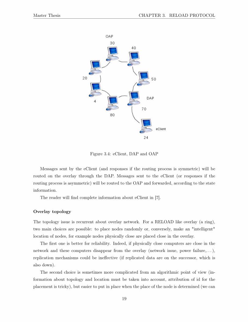
The new concept of enhanced client (eClient) has been proposed in [7] by V. Narayanan and A.
Swaminathan to deal with two possible issues: the mobility of a node inside the overlay, and the
topology of the overlay (nodes are placed randomly in the overlay, and the resulting situation
can be not optimal). Before a presentation of the solutions, a short overview of eClient concept
is requested to give the reader all the information s/he needs.
Despite the name, it is important to note that the eClients are functionally similar to peers.
Overview of eClient concept eClient operation allows a node to connect to an overlay via
an arbitrary peer (called here the Direct Attachment Point, DAP), not the node that owns
its identity (called the Overlay Attachment Point, OAP). The DAP is chosen to be a node
topologically close from the incoming peer. Doing this, the connection between the eClient and
the DAP will be easier to establish and maintain, less messages will be needed (saving power
for battery operated devices), . . . For example, a Bluetooth connection between the two nodes
can be enough.
Figure 3.4 depicts an example, with eClient (with NODE-ID 24), its OAP (NODE-ID 30) and
the DAP (with NODE-ID 70).
This solution brings some changes in some features of the RELOAD base protocol, like
bootstrap. Moreover, additional information are needed in eClient, OAP and DAP to route
messages, . . .
Concerning the bootstrap process, the DAP serves as the bootstrap peer (the discovery of
this peer is not specified).
After the join process, both OAP and DAP store state information about the eClient:
• the OAP creates forwarding state for the eClient with the DAP as the next hop. Every
message sent to the eClient will be forwarded to the DAP
• the DAP maintains a list of eClients attached to it.
18
Master Thesis CHAPTER 3. RELOAD PROTOCOL
Figure 3.4: eClient, DAP and OAP
Messages sent by the eClient (and responses if the routing process is symmetric) will be
routed on the overlay through the DAP. Messages sent to the eClient (or responses if the
routing process is asymmetric) will be routed to the OAP and forwarded, according to the state
information.
The reader will find complete information about eClient in [7].
Overlay topology
The topology issue is recurrent about overlay network. For a RELOAD like overlay (a ring),
two main choices are possible: to place nodes randomly or, conversely, make an "intelligent"
location of nodes, for example nodes physically close are placed close in the overlay.
The first one is better for reliability. Indeed, if physically close computers are close in the
network and these computers disappear from the overlay (network issue, power failure,. . . ),
replication mechanisms could be ineffective (if replicated data are on the successor, which is
also down).
The second choice is sometimes more complicated from an algorithmic point of view (in-
formation about topology and location must be taken into account, attribution of id for the
placement is tricky), but easier to put in place when the place of the node is determined (we can
19
Master Thesis CHAPTER 3. RELOAD PROTOCOL
assume that a connection between physically close computers is not more complicated, and in
some cases easier than a connection between two distant nodes) but can have a negative impact
on the reliability.
In [2], nodes are randomly placed into the overlay. This can bring a not optimal situation,
where nodes topologically far away have to establish and maintain connection. If a node could
choose to connect with a closer peer, fewer messages will be needed, power or bandwidth could
be saved,. . . The eClient concept can deal with this issue, since an eClient can connect to an
arbitrary peer in the overlay, and has the advantage that it is optional for all nodes involved.
Client mobility
An issue related to nodes is mobility. If a RELOAD node is mobile, it can connect, disconnect
and reconnect often and needs to update all data stored in the overlay with its new contact
information, in order to receive request messages. This behaviour is expensive in term of number
of messages, time,. . . Avoiding this could so be a good thing. A solution has been proposed in
[7], using the eClient.
After a first connection of the eClient, if it loses the connection with its DAP, but manages
to reconnect to the address it used for the DAP, the eClient can be back on the overlay without
having to re-join on the overlay (i.e. without having to redo the bootstrap operations).
Possible misunderstanding of eClient concept
A possible source of confusion has to be highlighted: in some situation, a Join request from an
eClient can be received by a peer (the OAP of the eClient). In this case, if the message has not
been received through the DAP (indicating that eClient can no longer connect to DAP), the peer
has to update the table of information it keeps about the eClient. In the normal situation, after
receiving a Join request, a peer triggers a series of Store requests for the incoming peer. Using
the same messages for two very different things could lead to misunderstandings. Maybe the
creation of a new message could solve the problem, in the same way that AppAttach messages
have been created to avoid confusion using Attach for two different things (according to some
discussions in the P2PSIP WG mailing list).
3.6.4 Variable length structure
In section 5.3.1.1 of the RELOAD base draft [2], one can read: "Like a NodeId, a Resource-ID
is an opaque string of bytes, but unlike Node-IDs, Resource-IDs are variable length, up to 255
bytes (2, 048 bits) in length. On the wire, each Resource-ID is preceded by a single length byte
(allowing lengths up to 255). Thus, the 3-byte value "Foo" would be encoded as: 03 46 4f 4f."
20

Master Thesis CHAPTER 3. RELOAD PROTOCOL
Following this sentence, a byte has to be added on the wire before Resource-ID, which
is a variable length structure. This byte is obviously necessary to parse the message and to
know how long the Resource-ID is. But, what in the case of other variable length structures
(for example the payload in the content of the message, opaque destination type in destination
and via lists, . . . )? Must a byte be added before every of these structures or only when it is
necessary and there is no other mean to compute the length?
Moreover, if this "length byte" has to be added on the wire, why not include it in the
structure of the data? It is not absolutely necessary but could match the structure of the data
and the flow of bytes on the wire.
3.6.5 Unknown Kind of Data
In the draft, section 6.4.1.1, one can read this: "Implementations SHOULD reject requests
corresponding to unknown kinds unless specifically configured otherwise." According to this
sentence and the signification of the SHOULD in [8], a RELOAD overlay could accept unknown
Kind of Data in particular circumstances. This is not the recommended behavior but it is
possible.
A few lines below in the same section, you can read "The peer MUST perform the following
checks: The Kind-ID is known and supported. [...] If all these checks succeed, the peer MUST
attempt to store the data values". Following this sentence, a peer must perform some checks
to verify the kind of data is known, and must store the data if all checks succeed. What is the
correct action if the RELOAD overlay is configured to accept unknown kinds?
One can assume that the specific setting (i.e. to accept unknown Kind of Data) is used
here, instead of the default behaviour, but it is not specified in the draft.
3.6.6 Unknown options
The Forwarding header of a RELOAD message can be extended with forwarding header options.
The structure of such an option is given in the draft, but to allow new usage, new options can
be easily created and used. Section 5.3.2.3 of the RELOAD base draft gives a definition of the
structure:
enum { (255) } ForwardingOptionsType;
struct {
ForwardingOptionsType type;
uint8 flags;
21
Master Thesis CHAPTER 3. RELOAD PROTOCOL
uint16 length;
select (type) {
/* Option values go here */
} option;
} ForwardingOption;
but the behaviour when an unknown option is used in a known data structure is not defined.
The same question can be asked when an unknown option is used in a unknown data structure.
3.6.7 Generation counter
The generation counter is used in the Store method. According to the draft, it represents "the
expected current state of the generation counter (approximately the number of times this object
has been written)" but, since "if there are multiple stored values in a single StoreKindData, it
is permissible for the peer to increase the generation counter by only 1 for the entire Kind-ID,
or by 1 or more than one for each value", the value of the generation counter can be quite far
from the definition, and it is more related to the kind of data than a single element. Specify in
more precisely the value to add could be a good thing for the sake of interoperability.
3.6.8 Detecting partitioning
Partitioning, for an overlay network, is when peers have different information about the state
of the overlay, when peers see the overlay differently (some nodes are missing for a node, the
same ones are present for another node,. . . ). Such a situation can bring a lot of problem, since
overlay algorithm can be performed in a inaccurately.
In Section 9.7.4.4 of the RELOAD base draft, one can read that "To detect that a parti-
tioning has occurred and to heal the overlay, a peer P MUST periodically repeat the discovery
process used in the initial join for the overlay to locate an appropriate bootstrap peer, B. P
should then send a Ping for its own Node-ID routed through B. If a response is received from
a peer S′, which is not P ’s successor, then the overlay is partitioned and P should send a
Attach to S′ routed through B, followed by an Update sent to S′. (Note that S′ may not be
in P ’s neighbor table once the overlay is healed, but the connection will allow S′ to discover
appropriate neighbor entries for itself via its own stabilization.)"
This last sentence is not easy to follow. At this point, how can we maintain that the overlay
is broken? Moreover, why a message sent by P should be routed through its successor S, since
if it sends the message through B, B and P are connected and the message can be resent to P
immediately?
22

Master Thesis CHAPTER 3. RELOAD PROTOCOL
An explanation could be there is a small mistake in the draft. If P sends a message to its
(Node-ID + 1) through B, it will be routed to the successor of P known by B. After receiving
the response, P can check whether the responder is its immediate successor S (in this case P
and B have the same successor for P and the situation is correct) or another node S′(in this
case the view of the overlay is not the same between P and B, and an overlay partitioning is
possible).
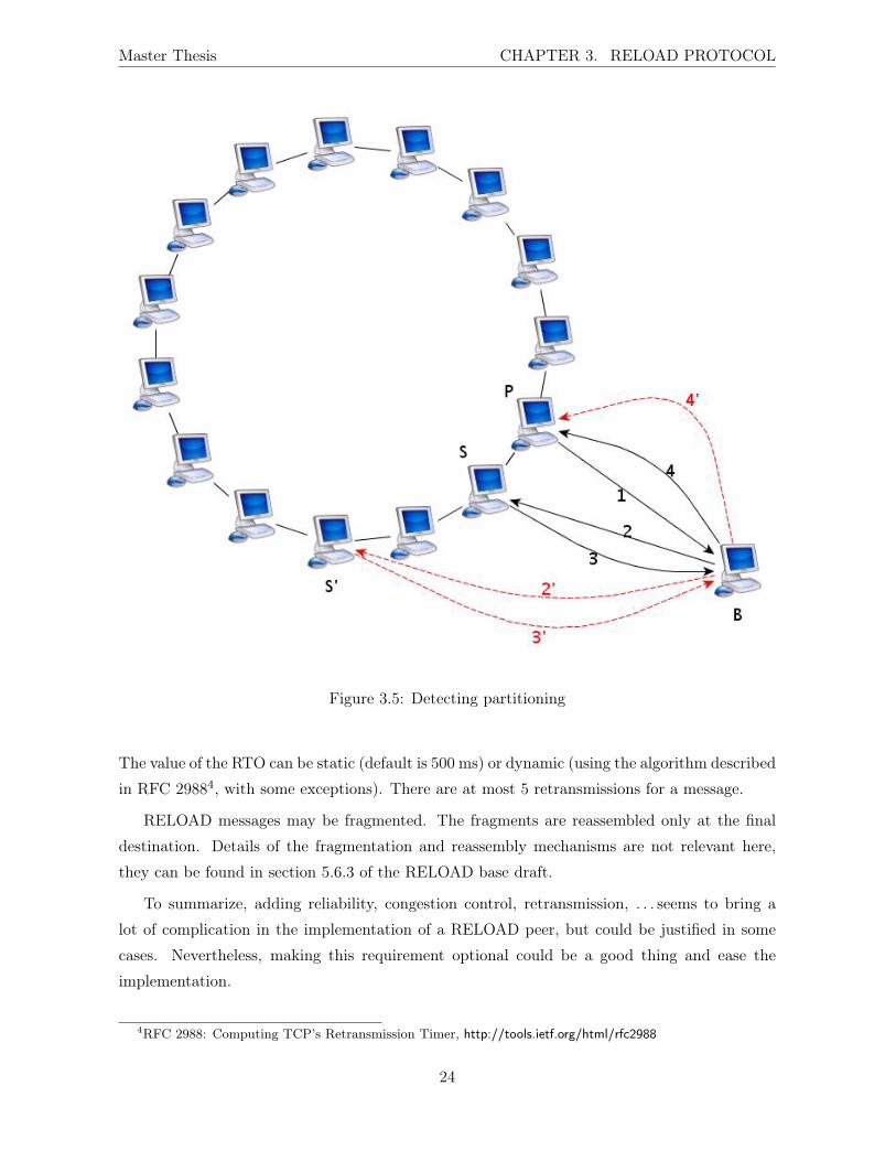
Figure 3.5 depicts such situation: the Ping message is sent by P (1 in the Figure 3.5) to
(Node-ID +1) through B.
In the normal case, the message is routed to S (2) and the response is received by P (3-4).
P now checks which node has sent the response. It is S so P and B have the same view of the
overlay.
In case of partition, the Ping message will be routed to another node S′ (2’). When P
receives the response (3’-4’), he can see that it has been sent by a node S′,and can now deduct
that B has a different view of the overlay (since for B, the node S is not P ’s successor, but S′
is).
3.6.9 Unreliable links
Allowing the use of unreliable links, whereas requesting the reliability of the message trans-
mission brings complexity to the implementation. Indeed, if DTLS or another unreliable link
protocol is used, "it needs to be used with a reliability and congestion control mechanism, which
is provided on a hop-by-hop basis, matching the semantics if TCP was used."[2]
The reliability is provided by an acknowledgment mechanism. At each hop, the receiver
sends an ACK message to the sender, containing the sequence number of the message.
The retransmission and flow control mechanism can be implemented in different ways. The
requirement is that the implementation must not be more aggressive than the TCP Friendly
Rate Control (TFRC)2. Three alternatives are proposed:
• a "default" implementation, section 5.6.2.2 of the RELOAD base draft;
• an implementation based on the additive increase, multiplicative decrease (AIMD) algo-
rithm in TCP;
• an implementation based on the TFRC in the Small Packet (TFRC-SP) variant3 , "and
use the received bitmask to allow the sender to compute packet loss event rates.[2]"
In brief, retransmission is done by a peer if it has not received an ACK for messages in a
interval of Retransmission TimeOut (RTO). After each retransmission the interval is doubled.2Requests For Comments (RFC) 5348: http://www.rfc-editor.org/rfc/rfc5348.txt3RFC 4828: http://tools.ietf.org/html/rfc4828
23
Master Thesis CHAPTER 3. RELOAD PROTOCOL
Figure 3.5: Detecting partitioning
The value of the RTO can be static (default is 500 ms) or dynamic (using the algorithm described
in RFC 29884, with some exceptions). There are at most 5 retransmissions for a message.
RELOAD messages may be fragmented. The fragments are reassembled only at the final
destination. Details of the fragmentation and reassembly mechanisms are not relevant here,
they can be found in section 5.6.3 of the RELOAD base draft.
To summarize, adding reliability, congestion control, retransmission, . . . seems to bring a
lot of complication in the implementation of a RELOAD peer, but could be justified in some
cases. Nevertheless, making this requirement optional could be a good thing and ease the
implementation.
4RFC 2988: Computing TCP’s Retransmission Timer, http://tools.ietf.org/html/rfc2988
24

Master Thesis CHAPTER 3. RELOAD PROTOCOL
3.6.10 ICE-TCP and ICE-Lite outdated
Implementing full ICE-TCP and ICE-Lite support is a mandatory requirement for the RELOAD
protocol, but neither ICE-TCP or ICE-Lite are making progress.
The last version of the draft 5 is from July 2008. Having normative dependencies on this
topic at this point seems problematic. And possible future implementations could bring a lot
of changes in the RELOAD base protocol, if the development process is continued in another
direction.
ICE-Lite is in the same situation, the last version of the draft 6 dates from February 2007.
3.6.11 Maximum size of a stored value
A possible issue related to the size of data could be the dynamic change of the overlay configura-
tion. With the Config_Update method, some overlay parameters can be dynamically changed,
max-size of data for example. In such a situation, [2] specifies that "if a node is not capable of
supporting the new requirements, it MUST exit the overlay." If the max-size is decreased on a
running overlay (for example to limit the use of bandwidth) what about the data stored which
exceed the size limit? One can assume that these data could be dropped, but it is also possible
that the change is temporary and the old size limit could be put back. In this case, removal of
data could result in a waste of time and bandwidth if they need to be re-stored in the overlay.
Moreover, the maximum size of a stored value has to be present in the configuration file of
the overlay, but the unit is not specified. The most likely unit is byte, but a precise information
would be a good thing.
3.6.12 Handling failures
Section 9.7.1 of the RELOAD base draft is dedicated to the handling of neighbor failures. One
can read that "If connectivity is lost to all the peers in the finger table, this peer should assume
that it has been disconnected from the rest of the network, and it should periodically try to join
the DHT." This sentence should be moved in the Section 9.7.2: Handling Finger Table Entry
Failure.
3.7 Related works
With the increase in the number of drafts in the WG, more and more aspects of RELOAD
have been covered. There are currently three working group documents (RELOAD base draft,
5http://tools.ietf.org/html/draft-ietf-mmusic-ice-tcp-076http://tools.ietf.org/id/draft-rescorla-mmusic-ice-lite-00.txt
25
Master Thesis CHAPTER 3. RELOAD PROTOCOL
SIP usage of RELOAD and diagnostics draft) and more than fifty related active documents
(of course some of these documents are outdated or currently useless but some are still under
development. To give a more complete overview of the RELOAD current situation and the
issues raised by these drafts, a short overview of the most important documents will be given
in this section.
The first concerns the diagnostics mechanism. As said above, this is a working group
document, and therefore an essential point concerning the RELOAD protocol.
The draft dependency graph can be found at the address http://www.fenron.com/~fenner/
ietf/deps/viz/p2psip.pdf.
3.7.1 Overlay diagnostics
Overlay networks are seen as a good platform for distributed systems because of, among other
things, their failure tolerance. But there are a lot of situations in which some peers of an
overlay may malfunction (peers misrouting messages, congested peers, network failure,. . . ), and
the consequence can be degradation of the quality of service, or an interruption of service.
To prevent as much as possible these drawbacks, it is useful to identify these malfunctioning
peers and exclude them from the overlay. To perform these operations, an overlay diagnostic
framework supporting periodic and on-demand methods for detecting node or network failures
is desirable [9].
Some methods, specific to the RELOAD Chord algorithm, are already present in the
RELOAD base document. But a specific extension, presenting a general P2PSIP overlay diag-
nostic has been proposed in [9].
In this part, mechanisms included in the base RELOAD protocol will be presented and
discussed. After, the overlay diagnostic framework presented in [9] will be discussed.
The following sections tackle some interesting documents related to the P2PSIP WG (but
not WG documents). As mentioned above, there are a lot of related active documents but only
documents which have been published in 2009 (and therefore still valid) have been taken into
account for the following sections.
3.7.2 Location and Discovery of Subsets of Resources
Mechanisms provided by the RELOAD protocol to efficiently search some resources may turn
out to be limited. [10] introduces the "location and discovery of filter resources selected by
search-conditions. The peers, which are virtually grouped, construct n-tuple overlay virtual
hierarchical tree overlay network. With cached addresses of peers, the overload of traffic in tree
structure can be avoided. The resources are classified into hierarchical domains, and registered
26
Master Thesis CHAPTER 3. RELOAD PROTOCOL
into the peers which are located in the same domain virtual groups as the resources. This
proposal supports flexible queries by a SQL-like query statement."
If the mechanism of resource classification can be extended to data, it could be very useful
when looking for data based on their characteristics instead of their names. With the hierarchical
classification, data semantics can be taken into account for a search. This classification could,
for example, be used with the hierarchical overlay proposition (see Section 3.7.4) to provide a
more complete search mechanism.
3.7.3 Pointers for Peer-to-Peer Overlay Networks, Nodes, or Resources
RELOAD has been designed to manage large overlay networks on the Internet. But providing
links (similar to Unified Resource Identifier (URI)) to an overlay in textual media like web
pages, email messages,. . . could be a good thing to make easier the search, the identification of
an overlay or the resources present in it. This proposition has been done in [11].
3.7.4 Hierarchical P2PSIP Overlay
With RELOAD, all the peers participating into the overlay are considered equal. But actually
peers can differ from each other on many aspects (physical, bandwidth or system performance,
storage capacities,. . . ) These differences should be taken into account to avoid some potentially
"bad" situation (critical or often accessed data stored on a peer with low bandwidth, . . . ). In
[12], authors "introduce the performance concerns of P2P SIP overlay without consideration
of node heterogeneity at first. After that, an alternative architecture of hierarchical P2P SIP
overlay is brought up."
Their solution is to divide an overlay into suboverlays using different classification algo-
rithms. These overlays hold equally powerful and stable nodes. An incoming peer will be
inserted in the lowest suboverlay (containing peers with the lowest capabilities), and will bring
up into the next if it has enough capabilities.
There are still a few open issues in the document, but this approach could bring some
improvement.
3.7.5 Traffic localization for RELOAD
In the RELOAD default mechanism, data are randomly distributed. It does not take into
account the geographical location information. This situation can bring some drawbacks. For
example, if the storing peer of a data is far away from data’s owner, the data has to be moved
through the entire overlay. The same situation can happen if the node needing the data is far
from the storing peer. For a peer-to-peer telephony service, this situation can unnecessarily
27
Master Thesis CHAPTER 3. RELOAD PROTOCOL
overload the network, since most of calls from or towards a particular node are geographically
close. In [13], authors propose a solution to take into account the location information to
minimize these effects.
3.7.6 Self-tuning Distributed Hash Table for RELOAD
In the RELOAD protocol, a lot of parameters have to be set to configure the DHT. Moreover,
some of these parameters can change dynamically. In [14], authors propose a "self-tuning version
of the Chord DHT algorithm". Their solution
• uses periodic stabilization,
• defines new Update, Leave messages (request and answer),
• defines new incorporation mechanism for peers into the finger table,
• defines new routine for successors and predecessors stabilization,
• defines new joining and leaving process, and
• defines mechanism to determine or estimate some parameters (overlay size, routing table
size, failure rate, join rate and stabilization interval).
This new algorithm is supposed to bring these benefits:
• No need to tune DHT parameters manually,
• The system adapts to changing operating conditions, and
• Low failure rate and low stabilization overhead. [15]
3.7.7 A Load Balancing Mechanism for RELOAD
Load balancing is an essential mechanism to manage data and provide services on overlay with
a satisfying quality of service. Without such strategy, overlay performance could be affected.
The problem of load balancing can be even more incapacitating in the case of heterogeneous
networks, where nodes’ capabilities (in terms of storage and/or bandwidth) can be very different.
In the worst cases, the imbalance in load distribution could create a bottleneck in the system.
Unfortunately, the RELOAD protocol with the Chord implementation does not support
operating in the overlay in a load balanced manner.
In [16], authors present a solution for load balancing the default DHT in RELOAD and avoid
the related problems. The solution is an improvement of the virtual nodes approach7 proposed7More information can be found in Chord: A Scalable Peer-to-Peer Lookup Service for Internet Applications,
http://pdos.csail.mit.edu/papers/chord:sigcomm01/chord_sigcomm.pdf
28

Master Thesis CHAPTER 3. RELOAD PROTOCOL
in "Heterogeneity and load balance in distributed hash tables"8. It works by "associating keys
with virtual nodes, and mapping multiple virtual nodes (with unrelated identifiers) to each real
node."
3.7.8 Topology Plug in for RELOAD
RELOAD is designed to be used with large scale overlay networks. However, one can find some
limitations in the functionalities provided by the default topology plug in. In [17], authors
propose another implementation of this plug in, bringing functionalities "that allow RELOAD
to operate under real world constraints":
• a load balancing algorithm,
• robust techniques for stabilization, self tuning mechanisms, and
• a locality aware finger selection algorithm.
The load balancing mechanism is quite close to the one described in section 3.7.7 and will
not be discussed here.
The current RELOAD base topology plug in is based on reactive stabilization. This tech-
nique may not be the most robust to a wide variety of network conditions and the authors
revisit this choice and recommend other techniques based on periodic stabilization.
The self-tuning DHT mechanism brings two main advantages (users no longer need to set
every DHT parameter correctly and the system adapts to changing operating conditions).
Finally, a locality aware routing "aims to mitigate the routing stretch of the topology plug
in so that a lookup is answered by making progress in the identifier space while minimizing the
amount of distance traveled in physical space at each hop."[17].
3.7.9 Deterministic Replication for RELOAD
Basic replication mechanism is natively provided by the RELOAD protocol. In [2], the replica-
tion is used to provide:
• persistence: to protect against data loss occurring from churn on the overlay,
• security: to avoid Denial of Service attacks or routing attacks by the responsible peer and
• load balancing to distribute the load of queries for resources.
8www.cs.berkeley.edu/~pbg/y0.pdf
29
Master Thesis CHAPTER 3. RELOAD PROTOCOL
The replication strategy is not specified in the RELOAD core, but is provided by the overlay
algorithm. The mandatory Chord implementation specifies to store two redundant copies of
data on the two immediate successors of a node.
This mechanism is essential but "does not address the problem of replication to meet the
availability requirements for a particular piece of data or to have the replicas be useful in some
inherent load balancing on the overlay"[18]
Additional mechanism has been proposed in [18] to provide "application-agnostic, determin-
istic replication on the overlay to meet these needs. The basic mechanism proposed here takes
target availability A for the data item that is being stored and determines the number of replicas
k, required to attain that target availability depending on the overlay network characteristics.
It then defines which K nodes should be used to store these replicas."[18]
3.7.10 A P2PSIP Client Routing for RELOAD
The RELOAD base draft [2] allows clients to connect either to the peer responsible for the
client’s Node-ID or to an arbitrary peer (based on the proximity, or the inability to establish
a direct connection with the responsible peer). In the second case, an issue relates to the
localization of the client in the overlay. Indeed, in this case the client is not connected to the
responsible peer and is not directly reachable using only its Node-ID. [19] " tries to define the
Client Routing protocol for locating a client that connects with an arbitrary peer in an overlay."
The proposed solution "is to store the information of a client’s Attached Peer in the overlay
together with the registration data of the client."[19]
3.7.11 P2PSIP Security Requirements
Security is one of the most important aspects when building an open network. RELOAD is
designed to be used with very large, open networks made up of untrusted nodes and security
must be guaranteed. To manage security, the RELOAD base draft [2] mandates several things:
• the use of TLS or DTLS for connections between peers,
• the use of X.509 certificates to sign each RELOAD message and
• the use of X.509 certificates to sign stored objects
Details about certificates can be found in the RFC 5280: Internet X.509 Public Key Infras-
tructure Certificate and Certificate Revocation List (CRL) Profile9.
These levels work together to check the origin and correctness of data they receive from
other peers[2].9http://tools.ietf.org/html/rfc5280
30
Master Thesis CHAPTER 3. RELOAD PROTOCOL
To avoid complications when a group of users wants to set up an overlay network without
being concerned with security, the use of self-signed and self-generated certificates is allowed.
In addition to the security considerations present in [2], extra information can be found
in two drafts: P2PSIP Security Requirements ([20]) and P2PSIP Security Overview and Risk
Analysis ([21]). These documents both discuss and analyze security requirements and threats
of P2PSIP systems.
3.7.12 Threat Analysis for Peer-to-Peer Overlay Networks
[22] "provides a threat analysis for peer-to-peer networks, where the system relies on each
individual peer to route message, store data, and provide services. The threats against P2P
networks include those that target individual peers, those that target routing protocols, those
that target identity management, and those that target stored data. Focusing on distributed
hash table based P2P network, authors first establish a threat model and perform a triage of
various assets in a P2P system. They then describe each individual threat in details, including
threat description, impact of attack, and possible mitigations. The threats and mitigations are
discussed under the context of feasibility and practicality, with the ultimate goal of achieving
better understanding of the threats for secure P2P system design."
3.8 Configuration of a RELOAD node
One of the main advantages of the P2P overlay network is the "self-organization" of the ap-
plication. In a RELOAD overlay, a node has to get an eXtensible Markup Language (XML)
configuration file from a server somewhere on the web to learn parameters such as listening
port, hash algorithm, length of the hashes produced by the algorithm (for Node-ID for exam-
ple), topology plugin for the management of the overlay, address and port of bootstrap peer(s),
. . . Fifteen parameters can be found in the configuration file. An example of configuration file
is:
?xml version="1.0" encoding="UTF-8"?>
<?oxygen RNGSchema="config-schema.rnc" type="compact"?>
<overlay xmlns="urn:ietf:params:xml:ns:p2p:config-base"
xmlns:ext="urn:ietf:params:xml:ns:p2p:config-ext1"
xmlns:chord="urn:ietf:params:xml:ns:p2p:config-chord-128-2">
<configuration instance-name="overlay.example.org" sequence="22"
expiration="2002-10-10T07:00:00Z">
31

Master Thesis CHAPTER 3. RELOAD PROTOCOL
<attach-lite-permitted>false</attach-lite-permitted>
<bootstrap-peer>192.0.0.1:5678</bootstrap-peer>
<bootstrap-peer>192.0.2.2:6789</bootstrap-peer>
<initial-ttl> 30 </initial-ttl>
<clients-permitted>false</clients-permitted>
<max-message-size>4000</max-message-size>
<credential-server>https://example.org</credential-server>
<ext:example-extention> foo </ext:example-extention>
<multicast-bootstrap>192.0.0.3:5678</multicast-bootstrap>
<chord:probe-frequency>300</chord:probe-frequency>
<chord:update-frequency>400</chord:update-frequency>
<self-signed-permitted digest="sha1">false</self-signed-permitted>
<shared-secret>asecret</shared-secret>
<topology-plugin>Chord-128-2-16</topology-plugin>
<root-cert>TODO</root-cert>
<required-kinds>
<kind name="sip-registration">
<data-model>single</data-model>
<access-control>user-match</access-control>
<max-count>1</max-count>
<max-size>100</max-size>
</kind>
<kind id="2000">
<data-model>array</data-model>
<access-control>user-match</access-control>
<max-count>22</max-count>
<max-size>4</max-size>
<ext:example-kind-extention>1</ext:example-kind-extention>
</kind>
</required-kinds>
</configuration>
<signature>TODO BASE 64 encoded signature block</signature>
</overlay>
32

Master Thesis CHAPTER 3. RELOAD PROTOCOL
To configure a RELOAD overlay, this type of file is necessary. Indeed, RELOAD is designed
to be generic and provide an interface to a distributed hash table. So, even with a RELOAD
compliant implementation, many parameters shall be set before the RELOAD overlay can really
be used by an application. But, with a configuration file with all these parameters, can we still
talk about "self-organization"?
Some people find this way inefficient, and think that a better way to configure the overlay
could be found, maybe using another XML schema language like RELAX NG 10. Using this
language makes the file easier to read for a human (and maybe to parse), but this is still an
XML file.
Finding a better way to configure RELOAD nodes seems difficult in the case of an open,
large scale, unsecure overlay in the Internet (a lot of parameters have to be set, in one way or
another), but self-tuning DHT (as discussed above in Section 3.7.6) could bring advantages and
more simplicity in the configuration of a node.
Another important aspect is the security of this configuration file. Indeed, it has to be
available from a HTTPS server, but its security and integrity have to be guaranteed. If this
file can be modified or replaced, consequences on the overlay could be considerable. Moreover,
with the introduction of the Config_Update since the third version of the RELOAD base draft,
this configuration file could be quickly allocated to every node in the overlay.
10http://relaxng.org/
33

Chapter 4
Usages of RELOAD
In this chapter, a few possible usages of RELOAD will be presented. The first one concerns the
SIP usage of RELOAD , which is the most expected one. Indeed, the RELOAD overlay has
been explicitly developed to be used as a SIP proxy and/or registrar.
The following sections are brief overviews of other possible usages, namely:
• Domain Name System (DNS)
• Jabber/eXtensible Messaging and Presence Protocol (XMPP)
• Content Delivery Network (CDN)
4.1 SIP usage of RELOAD
One of the first potential applications for RELOAD was to replace the SIP proxy and/or the
SIP registrar. Of course, the removal of one or both elements can bring some advantages like
failure tolerance, scalability, no need of a central server,. . . The SIP use of RELOAD involves
two functions.
The first is the registration. SIP UA can use the RELOAD overlay (with the data stor-
age functionality) to store a mapping between their AOR and their Node-ID in the overlay.
They can also retrieve the Node-ID of other UAs from the overlay. To register its loca-
tion, a RELOAD node stores a specific SipRegistration structure under its own AOR. This
structure uses the SIPREGISTRATION Kind-ID. For example, Alice can store the mapping
"sip:[email protected] -> 5678" and everyone who wants to contact Alice knows that s/he has
to send a message to Node-ID 5678. Of course, you can also store a mapping AOR to AOR. In
this case, if Alice stores the mapping "sip:[email protected] -> sip:[email protected]", a SIP
UA who wants to call Alice will receive Carol’s AOR and will call her.
35

Master Thesis CHAPTER 4. USAGES OF RELOAD
The second function is the Rendezvous management. Once a SIP user agent has identified
the Node-ID of the user agent it wishes to call, it uses the RELOAD message routing system to
set up a direct connection between the UAs for exchange SIP messages.
With these two functions, we can see one more time the two big aspects of RELOAD. The
first one concerns the data management system (storage, duplication, retrieval, removal,. . . ).
This is, in outline, the DHT part of the protocol. The second one concerns the message routing
system (with the establishment of connections, the collection of information like ICE candidates,
. . . )
To illustrate these functions, and compare with the classical SIP scenario, let’s take an ex-
ample. The users (Alice and Bob for example) store the mapping AOR-NodeID in the RELOAD
overlay, with a RELOAD Store request. Each of the mappings will be stored by a peer some-
where in the overlay, following the topology plug in of the overlay.
When Alice wants to call Bob, instead of sending an INVITE to her proxy, she does a
RELOAD Fetch request with the key (or the hash of the key) "Bob", she receives the Node-ID
of Bob and can send a AppAttach request with this Node-ID as destination. The message will
be routed towards the node of Bob, collecting informations (like ICE(-Lite) candidates,. . . ).
Bob will respond with an AppAttach message, collecting same information (ICE(-Lite) candi-
dates,. . . ) throughout the journey of the message. As a result, a direct connection can be
established between Alice and Bob, and they can start to send classical SIP messages to each
other. At this point, RELOAD overlay is no longer involved into the transaction (or the SIP
call) until it ends.
This scenario is depicted in Figure 4.1.
An important point to keep in mind is that in this case, the SIP UA must be running
on a RELOAD peer, so must have a complete RELOAD implementation. It is not "just" an
application client, a pure SIP client like a SIP phone. A first possible improvement could be to
allow SIP UA to run on RELOAD clients, and a second (and more important one) could be to
specify a SIP usage with "pure" SIP clients, having no knowledge of RELOAD but using the
overlay as a classical proxy/registrar, with all its potential uses.
A draft [23] has been proposed to take the case of "pure" application clients into account.
Briefly, this document tries to solve drawbacks of [24]:
• trouble in inter-domain interworking (a peer of overlay A must be present in the overlay
B if a SIP user in A and a SIP user in B must communicate);
• trouble in SIP users’ mobility (peers’ mobility and churn of the overlay); and
• exclusivity towards overlay clients in SIP usage.
The process of a SIP call using this solution is depicted in figure 4.2.
36
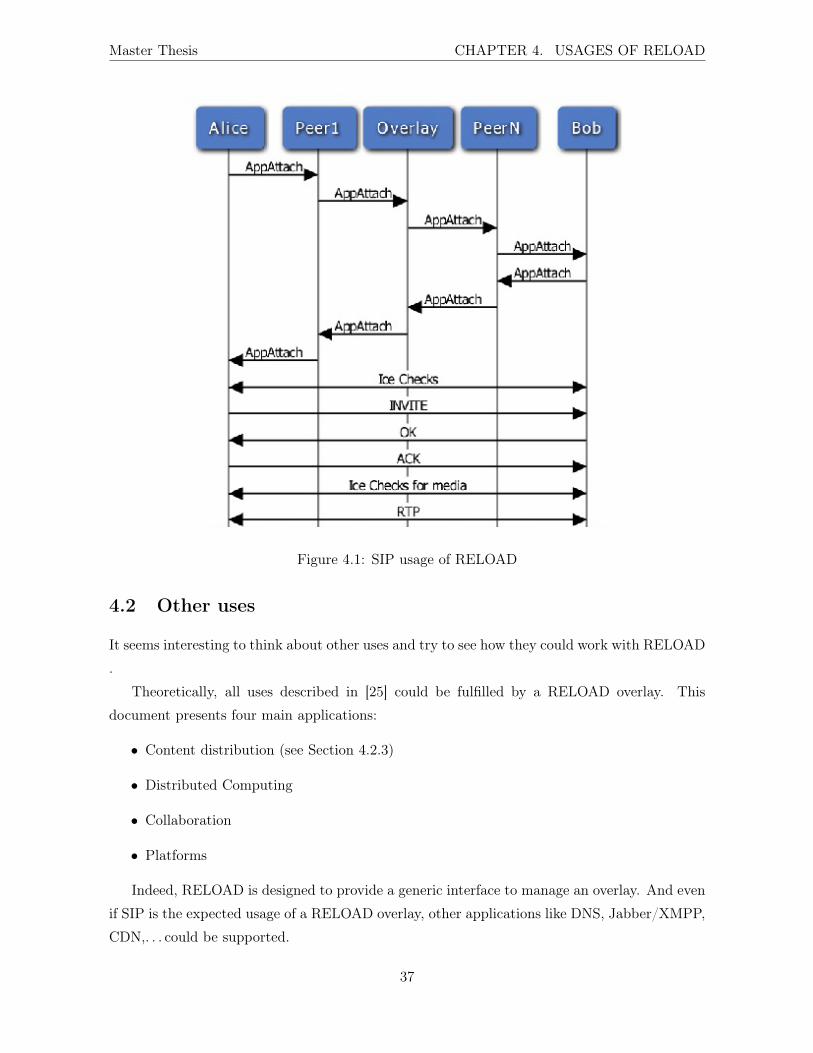
Master Thesis CHAPTER 4. USAGES OF RELOAD
Figure 4.1: SIP usage of RELOAD
4.2 Other uses
It seems interesting to think about other uses and try to see how they could work with RELOAD
.
Theoretically, all uses described in [25] could be fulfilled by a RELOAD overlay. This
document presents four main applications:
• Content distribution (see Section 4.2.3)
• Distributed Computing
• Collaboration
• Platforms
Indeed, RELOAD is designed to provide a generic interface to manage an overlay. And even
if SIP is the expected usage of a RELOAD overlay, other applications like DNS, Jabber/XMPP,
CDN,. . . could be supported.
37
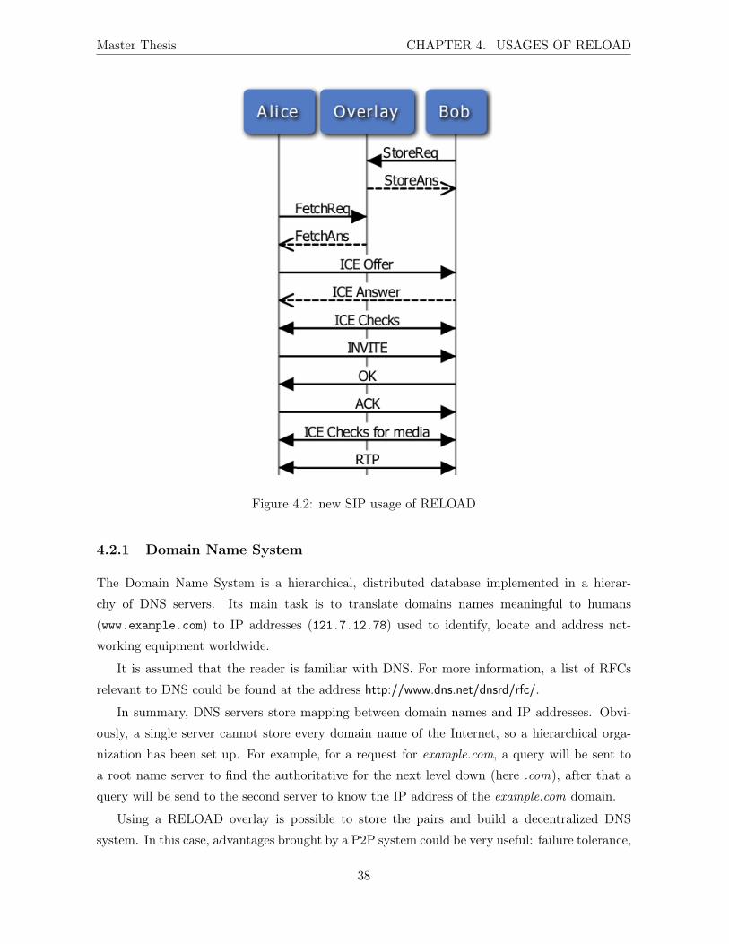
Master Thesis CHAPTER 4. USAGES OF RELOAD
Figure 4.2: new SIP usage of RELOAD
4.2.1 Domain Name System
The Domain Name System is a hierarchical, distributed database implemented in a hierar-
chy of DNS servers. Its main task is to translate domains names meaningful to humans
(www.example.com) to IP addresses (121.7.12.78) used to identify, locate and address net-
working equipment worldwide.
It is assumed that the reader is familiar with DNS. For more information, a list of RFCs
relevant to DNS could be found at the address http://www.dns.net/dnsrd/rfc/.
In summary, DNS servers store mapping between domain names and IP addresses. Obvi-
ously, a single server cannot store every domain name of the Internet, so a hierarchical orga-
nization has been set up. For example, for a request for example.com, a query will be sent to
a root name server to find the authoritative for the next level down (here .com), after that a
query will be send to the second server to know the IP address of the example.com domain.
Using a RELOAD overlay is possible to store the pairs and build a decentralized DNS
system. In this case, advantages brought by a P2P system could be very useful: failure tolerance,
38

Master Thesis CHAPTER 4. USAGES OF RELOAD
elimination of a possible single point of failure, load balancing between servers, security, . . . From
this point of view, this usage could be compared to the Round Robin DNS concept.
Section 4.1.2 of the RELOAD base draft specifies things necessary to define a new usage:
• Register Kind-ID code points for any kind that the Usage defines.
• Define the data structure for each of the kinds
• Define access control rules for each kind
• Define how the Resource Name is formed that is hashed to form the Resource-ID where
each kind is stored
• Describe how values will be merged after a network partition
More information about data model and access control policies can be found in Sections 6.2
and 6.3 of the RELOAD base draft.
Currently, there are almost thirty record types defined by DNS. In this work, only records
of type A (for a 32-bit IPv4 addresses) will be used, but the mechanism is the same for other
types of record.
Lines below define the DNS-A-RECORD type.
Name DNS-A-RECORD.
Kind-IDs The Resource Name for the DNS-A-RECORD Kind-ID is the domain name. The
data stored in a DnsARecordData is the IPv4 address of a given domain. The Resource-ID is
the hash of the domain name.
Data Model The data model for the DNS-A-RECORD Kind-ID is dictionary. The use of
dictionary instead of single value enables having multiple IP addresses for the same domain
name.
When a peer is looking for an address, it hashes the domain name, obtains a Resource-ID
and sends a RELOAD Fetch message with it. It receives a set of data and chooses one of them
to make the mapping.
Access Control Policy The policy is USER-NODE-MATCH. This policy specifies that "a
given value MUST be written (or overwritten) if and only if the request is signed with a key
associated with a certificate whose user name hashes (using the hash function for the overlay)
to the Resource-ID for the resource. In addition, the dictionary key MUST be equal to the
Node-ID in the certificate. [2]"
39

Master Thesis CHAPTER 4. USAGES OF RELOAD
Other security problems related to DNS (like DNS cache poisoning) could be avoided, since
all messages have to be signed with a certificate.
The overlay itself is built with servers, acting as peers from the RELOAD point of view,
and is not accessible from the outside. Requests are sent in the classical way, and RELOAD is
only used by the servers.
This usage of RELOAD should not pose any problem and could bring advantages. Obviously,
the case of type A DNS records is one of the numerous possibilities and other types of records
could maybe be a problem.
On the other hand, P2P DNS solutions have been planned (inside the WG, in collaboration
with RELOAD , or outside the WG11) but have been abandoned. It appears that peer-to-peer
systems have fundamental limitations and simply are not appropriate for applications that need:
• Lower latency.
• Protection against insertion DoS.
• Choice of functionality for network outages.
• More than just distributed hash tables.
• High confidence in the network.
• Generic incentives for people to run servers.[26]
4.2.2 Jabber/XMPP
XMPP is an open, XML-based protocol used (among others) for instant messaging and presence
information. It is the core protocol of Jabber Instant Messaging and Presence technology, and is
used by some very important actors in the IM world like Google for Google Talk, and AOL was
considering using it [27]. The protocol is an open standard, developed by the XMPP Working
group12.
One of the problems of XMPP, according to some authors, is the scalability of the server.
Because scalability is one of the major advantages of using P2P overlay, using a RELOAD
overlay to act as a XMPP server could make sense.
According to XMPP RFC [28], primary responsibilities of a XMPP server are:
• to manage connections from or sessions for other entities, in the form of XML streams to
and from authorized clients, servers and other entities11http://sourceforge.net/projects/p2pdns/12http://tools.ietf.org/wg/xmpp/
40
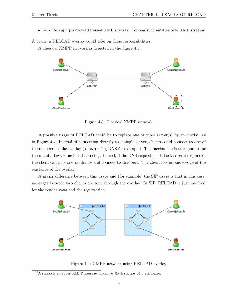
Master Thesis CHAPTER 4. USAGES OF RELOAD
• to route appropriately-addressed XML stanzas13 among such entities over XML streams
A priori, a RELOAD overlay could take on these responsibilities.
A classical XMPP network is depicted in the figure 4.3.
Figure 4.3: Classical XMPP network
A possible usage of RELOAD could be to replace one or more server(s) by an overlay, as
in Figure 4.4. Instead of connecting directly to a single server, clients could connect to one of
the members of the overlay (known using DNS for example). The mechanism is transparent for
them and allows some load balancing. Indeed, if the DNS request sends back several responses,
the client can pick one randomly and connect to this peer. The client has no knowledge of the
existence of the overlay.
A major difference between this usage and (for example) the SIP usage is that in this case,
messages between two clients are sent through the overlay. In SIP, RELOAD is just involved
for the rendez-vous and the registration.
Figure 4.4: XMPP network using RELOAD overlay
13A stanza is a Jabber/XMPP message. It can be XML stanzas with attributes.
41
Master Thesis CHAPTER 4. USAGES OF RELOAD
When a XMPP client ([email protected]) connects to one of the peers in the overlay (RA, for
Responsible for Alice), the peer RA has to store in the overlay the information about the client.
For example, if RA has Node-ID 15, this node will store a mapping between "[email protected]"
(or its hash) and "Node-ID 15". When Bob wants to talk to Alice, it sends a message through its
own server (RB, the peer in the overlay to which it is connected) as usual. The peer RB will re-
trieve from the overlay (with RELOAD Fetch method) the mapping between "[email protected]"
and the Node-ID. The result is 15, so the peer RB knows that XMPP messages will be exchanged
between them. The connection between RA and RB will be established using the AppAttach
method. This method has been especially added to the protocol to open a TCP (or UDP)
connection between two nodes for sending application layer data. At this point, XMPP mes-
sages can be sent from Alice to RA to RB to Bob without any problem, since the connection is
especially dedicated to application layer messages and RELOAD is no longer involved.
Another case could be if the two users are not connected to the same server. Indeed, with
Jabber, Alice, connected to jabber.be server can talk without problem with Carol connected to
jabber.fr. In this case, messages will be sent from one server to the other via the Internet.
If one of the servers is a RELOAD overlay, there has to be a mapping between the domain
jabber.fr and the Node-ID of the peer connected to this server (50 for example). If Alice
wants to talk with Carol, her message is sent to her responsible peer, this peer retrieves the
mapping between jabber.fr and the Node-ID 50, opens a TCP connection with the node 50
using AppAttach. After that, messages for Carol will be sent to this node, and forwarded to
the server jabber.fr as regular XMPP messages.
So far, the overlay must contain both user to Node-ID mapping and domain to Node-ID
mapping.
Now, it is possible to define a new kind of data for a XMPP usage of RELOAD .
Name XMPP-MAPPING
Kind-IDs The Resource name for the Kind-ID XMPP-MAPPING is the Node-ID of the node
connected to the Jabber client or the other Jabber server.
Data Model The data model for the XMPP-MAPPING Kind-ID is dictionary. The key is
the Jabber ID or the domain. This allows peers to search either for a user or an entire domain.
Access Control Policy USER-NODE-MATCH.
In this case, using RELOAD as a XMPP server seems possible too. A more complete study
would be necessary to determine at which point a single hosted Jabber/XMPP server would
42
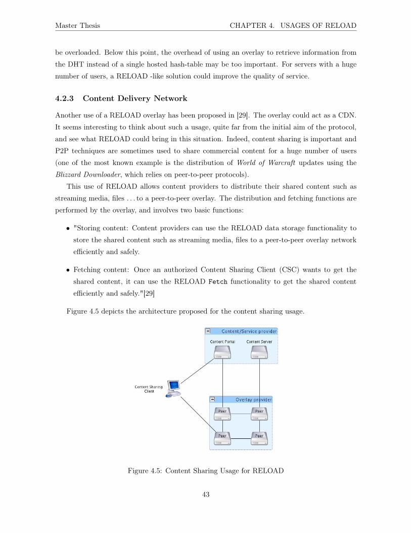
Master Thesis CHAPTER 4. USAGES OF RELOAD
be overloaded. Below this point, the overhead of using an overlay to retrieve information from
the DHT instead of a single hosted hash-table may be too important. For servers with a huge
number of users, a RELOAD -like solution could improve the quality of service.
4.2.3 Content Delivery Network
Another use of a RELOAD overlay has been proposed in [29]. The overlay could act as a CDN.
It seems interesting to think about such a usage, quite far from the initial aim of the protocol,
and see what RELOAD could bring in this situation. Indeed, content sharing is important and
P2P techniques are sometimes used to share commercial content for a huge number of users
(one of the most known example is the distribution of World of Warcraft updates using the
Blizzard Downloader, which relies on peer-to-peer protocols).
This use of RELOAD allows content providers to distribute their shared content such as
streaming media, files . . . to a peer-to-peer overlay. The distribution and fetching functions are
performed by the overlay, and involves two basic functions:
• "Storing content: Content providers can use the RELOAD data storage functionality to
store the shared content such as streaming media, files to a peer-to-peer overlay network
efficiently and safely.
• Fetching content: Once an authorized Content Sharing Client (CSC) wants to get the
shared content, it can use the RELOAD Fetch functionality to get the shared content
efficiently and safely."[29]
Figure 4.5 depicts the architecture proposed for the content sharing usage.
Figure 4.5: Content Sharing Usage for RELOAD
43
Master Thesis CHAPTER 4. USAGES OF RELOAD
The main components of the content sharing usage of RELOAD are:
• Content/Service provider: The owner of the shared content. This component provides
two functionalities, storing the shared content (store full content or content segment into
the overlay network) and providing content portal (publishing information for the content
that CSC can access).
• Overlay provider: the owner of the overlay network. The overlay is built and run using
RELOAD .
• CSC: it is used to get the content. It retrieves the information about the content by
contacting the content portal first. Then it fetches the content from the overlay.
This usage of RELOAD is quite far from the predicted one, but could bring some advantages.
Security and NAT traversal, for example, are natively present with RELOAD .
44
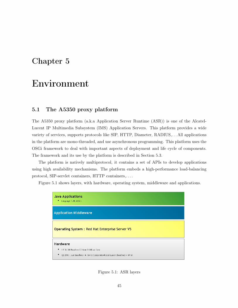
Chapter 5
Environment
5.1 The A5350 proxy platform
The A5350 proxy platform (a.k.a Application Server Runtime (ASR)) is one of the Alcatel-
Lucent IP Multimedia Subsystem (IMS) Application Servers. This platform provides a wide
variety of services, supports protocols like SIP, HTTP, Diameter, RADIUS,. . . All applications
in the platform are mono-threaded, and use asynchronous programming. This platform uses the
OSGi framework to deal with important aspects of deployment and life cycle of components.
The framework and its use by the platform is described in Section 5.3.
The platform is natively multiprotocol, it contains a set of APIs to develop applications
using high availability mechanisms. The platform embeds a high-performance load-balancing
protocol, SIP-servlet containers, HTTP containers,. . . .
Figure 5.1 shows layers, with hardware, operating system, middleware and applications.
Figure 5.1: ASR layers
45
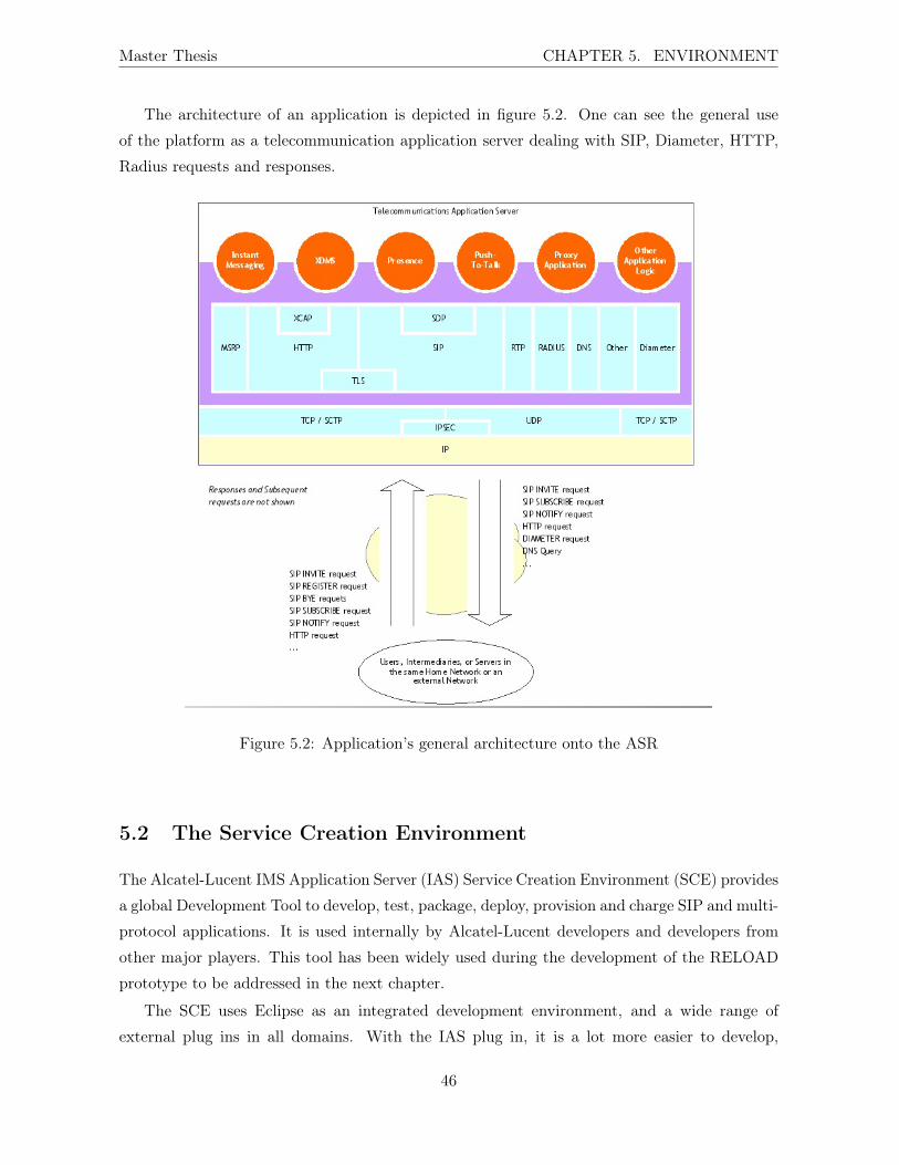
Master Thesis CHAPTER 5. ENVIRONMENT
The architecture of an application is depicted in figure 5.2. One can see the general use
of the platform as a telecommunication application server dealing with SIP, Diameter, HTTP,
Radius requests and responses.
Figure 5.2: Application’s general architecture onto the ASR
5.2 The Service Creation Environment
The Alcatel-Lucent IMS Application Server (IAS) Service Creation Environment (SCE) provides
a global Development Tool to develop, test, package, deploy, provision and charge SIP and multi-
protocol applications. It is used internally by Alcatel-Lucent developers and developers from
other major players. This tool has been widely used during the development of the RELOAD
prototype to be addressed in the next chapter.
The SCE uses Eclipse as an integrated development environment, and a wide range of
external plug ins in all domains. With the IAS plug in, it is a lot more easier to develop,
46
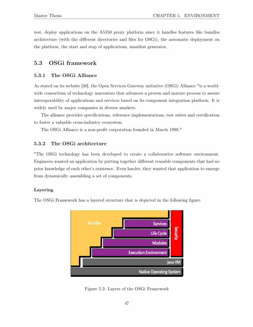
Master Thesis CHAPTER 5. ENVIRONMENT
test, deploy applications on the A5350 proxy platform since it handles features like bundles
architecture (with the different directories and files for OSGi), the automatic deployment on
the platform, the start and stop of applications, manifest generator.
5.3 OSGi framework
5.3.1 The OSGi Alliance
As stated on its website [30], the Open Services Gateway initiative (OSGi) Alliance "is a world-
wide consortium of technology innovators that advances a proven and mature process to assure
interoperability of applications and services based on its component integration platform. It is
widely used by major companies in diverse markets.
The alliance provides specifications, reference implementations, test suites and certification
to foster a valuable cross-industry ecosystem.
The OSGi Alliance is a non-profit corporation founded in March 1999."
5.3.2 The OSGi architecture
"The OSGi technology has been developed to create a collaborative software environment.
Engineers wanted an application by putting together different reusable components that had no
prior knowledge of each other’s existence. Even harder, they wanted that application to emerge
from dynamically assembling a set of components.
Layering
The OSGi Framework has a layered structure that is depicted in the following figure.
Figure 5.3: Layers of the OSGi Framework
47
Master Thesis CHAPTER 5. ENVIRONMENT
The following list contains a short definition of the terms:
• Bundles - Bundles are the OSGi components designed, implemented and tested by the
developers.
• Services - The service layer connects bundles in a dynamic way by offering a publish-find-
bind model for plain old Java objects.
• Life-Cycle - The API to install, start, stop, update, and uninstall bundles.
• Modules - The layer that defines how a bundle can import and export code.
• Security - The layer that handles the security aspects.
• Execution Environment - Defines what methods and classes are available in a specific
platform.
These concepts are more extensively explained in the following paragraphs.
Modules
The fundamental concept that enables such a system is modularity. Modularity, simplistically
said, is about assuming less. Modularity is about keeping things local and not sharing. Mod-
ularity is at the core of the OSGi specifications and embodied in the bundle concept. In Java
terms, a bundle is a plain old Java ARchive (JAR) file. However, where in standard Java ev-
erything in a JAR is completely visible to all other JARs, OSGi hides everything in that JAR
unless explicitly exported. A bundle that wants to use another JAR must explicitly import the
parts it needs. By default, there is no sharing.
Services
The reason the service model is needed is because Java shows how hard it is to write collaborative
models with only class sharing. The standard solution in Java is to use factories that use
dynamic class loading and statics.
With the OSGi service registry, a bundle can create an object and register it with the OSGi
service registry under one or more interfaces. Other bundles can go to the registry and list all
objects that are registered under a specific interface or class.
A bundle can therefore register a service, it can get a service, and it can wait for a service
to appear or disappear. Any number of bundles can register the same service type, and any
number of bundles can get the same service.
48
Master Thesis CHAPTER 5. ENVIRONMENT
Each service registration has a set of standard and custom properties. An expressive filter
language is available to select only the services in which you are interested. Properties can be
used to find the proper service or can play other roles at the application level.
Services are dynamic. This means that a bundle can decide to withdraw its service from
the registry while other bundles are still using this service. The service dynamics were added
so it is possible to install and uninstall bundles on the fly while the other bundles could adapt.
The availability of the service models the availability of a real world entity. It also turns out
that the dynamics solve the initialization problem. OSGi applications do not require a specific
start ordering in their bundles.
In conclusion, the OSGi specifications provide a mature and comprehensive component
model with a very effective (and small) API. Converting monolithic or home grown plug in
based systems to OSGi almost always provides great improvements in the whole process of
developing software [30]".
5.3.3 Presentation of the OSGi Technology
In this section, OSGi technology will be shortly explained.
"The core component of the OSGi Specifications is the OSGi Framework. The Framework
provides a standardized environment to applications (called bundles). The Framework is divided
in a number of layers.
• L0: Execution Environment
• L1: Modules
• L2: Life Cycle Management
• L3: Service Registry
• An ubiquitous security system is deeply intertwined with all the layers.
The L0 Execution Environment layer is the specification of the Java environment. Java 2
Configurations and Profiles, like Java 2 Standard Edition (J2SE), Connected Device Configu-
ration (CDC), Connected Limited Device Configuration (CLDC), Mobile Information Device
Profile (MIDP) etc. are all valid execution environments.
The L1 Modules layer defines the class loading policies. The OSGi Framework is a powerful
and rigidly specified class-loading model. It is based on top of Java but adds modularization. In
Java, there is normally a single classpath that contains all the classes and resources. The OSGi
Modules layer adds private classes for a module as well as controlled linking between modules.
49
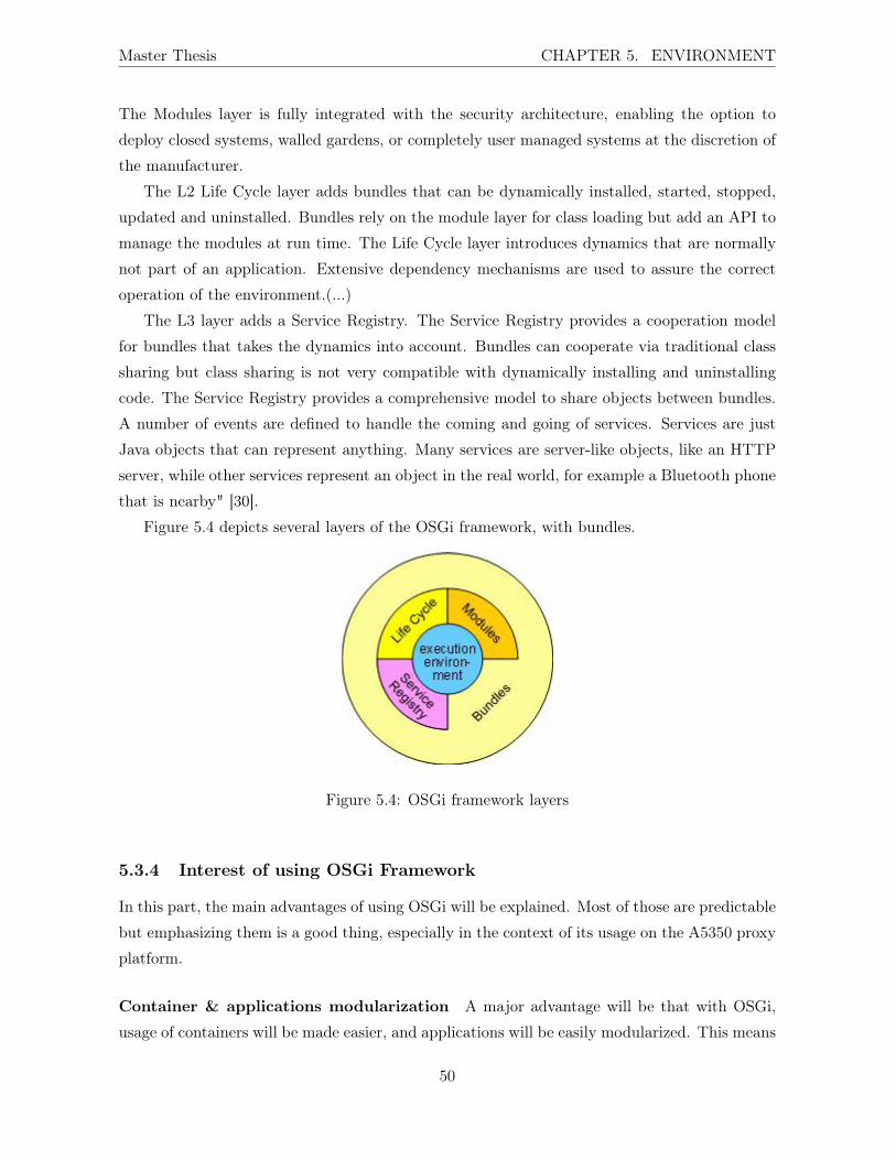
Master Thesis CHAPTER 5. ENVIRONMENT
The Modules layer is fully integrated with the security architecture, enabling the option to
deploy closed systems, walled gardens, or completely user managed systems at the discretion of
the manufacturer.
The L2 Life Cycle layer adds bundles that can be dynamically installed, started, stopped,
updated and uninstalled. Bundles rely on the module layer for class loading but add an API to
manage the modules at run time. The Life Cycle layer introduces dynamics that are normally
not part of an application. Extensive dependency mechanisms are used to assure the correct
operation of the environment.(...)
The L3 layer adds a Service Registry. The Service Registry provides a cooperation model
for bundles that takes the dynamics into account. Bundles can cooperate via traditional class
sharing but class sharing is not very compatible with dynamically installing and uninstalling
code. The Service Registry provides a comprehensive model to share objects between bundles.
A number of events are defined to handle the coming and going of services. Services are just
Java objects that can represent anything. Many services are server-like objects, like an HTTP
server, while other services represent an object in the real world, for example a Bluetooth phone
that is nearby" [30].
Figure 5.4 depicts several layers of the OSGi framework, with bundles.
Figure 5.4: OSGi framework layers
5.3.4 Interest of using OSGi Framework
In this part, the main advantages of using OSGi will be explained. Most of those are predictable
but emphasizing them is a good thing, especially in the context of its usage on the A5350 proxy
platform.
Container & applications modularization A major advantage will be that with OSGi,
usage of containers will be made easier, and applications will be easily modularized. This means
50

Master Thesis CHAPTER 5. ENVIRONMENT
that reuse of components will be very easy, they could be shared and called by other applications
easily (the bundle just will ask what it needs to use the registry).
In the case of the RELOAD implementation, the modularization will bring a very important
advantage. Indeed, the RELOAD protocol is made of a few components, which (theoretically)
could be used independently from each other. The best example is the topology plug-in. This
plug-in deals with the overlay algorithm, the core of the DHT management. With the modu-
larization, several topology plug-ins (with several DHT algorithm) could be implemented and
deployed when necessary. The other components will not have to be replaced or modified. More
information about implementation can be found in Chapter 6.
Life cycle of the container With OSGi, bundles can be dynamically installed, started,
stopped, updated and uninstalled without bringing down the whole system. This has of course
great advantages like deployment times, no down time of server,. . . . Moreover, the OSGi
technology also specifies how components are installed and managed, through command shell,
graphical interface,. . . .
Again, this advantage will be helpful in the case of the RELOAD implementation. A compo-
nent could be stopped and replaced by another (for example another topology plug-in) without
stopping the RELOAD application (in RELOAD terms, without stopping the node). This can
be helpful when the configuration changes (see Section 3.8 for further information).
Object bundle repository With the Object Bundle Repository (OBR), bundles can be
placed in a single location and be fetched and deployed by an application running on a different
computer. This brings advantages in terms of deployment, update, replacement of bundles.
On the OSGi website [30],the reader will find a more complete list of advantages, among
others
• reduced complexity,
• reuse,
• adaptability,
• transparency,
• simplicity,
• security,. . .
51

Chapter 6
Implementation
The initial goal was to implement the RELOAD protocol onto the A5350 platform in addition
to already supported ones (HTTP, SIP, Diameter,. . . ).
A recurrent idea was to use a DHT into the platform to replace the fast cache compo-
nent. The configuration server, another name for the fast cache, centralizes configuration,
performance and fault management data. It also contains information about (for example) SIP
sessions,. . . This is a central and critical component for the platform, and the initial idea was
to study which advantages the RELOAD protocol could bring in this case. The fast cache is a
large, centralized DHT and is used by almost every component in the platform. Of course, to
ensure reliability, replication mechanisms have been set up. A slave fast cache can be deployed
on another host, the original one will automatically replicate its data in the so-called slave
configuration server.
From a theoretical point of view, use a DHT and a ring to store the information is obviously
a good thing. It brings scalability with the possible use of more than one host for a single fast
cache component, failure tolerance, replication of data,. . . The use of P2P techniques and DHT
instead of a centralized component could be a really good thing, with a special attention for
requirements (reliability, high availability, recovery, well defined state of the overlay, . . . ) of a
professional IMS platform (for example a node of a P2P network could crash or disconnect, no
big deal. But it can not happen in a professional product).
The whole implementation has been done using asynchronous "single thread" programming
(all others applications running on the A5350 platform use this technique too) , and following
the "doXXX()" pattern, like in the SipServlet14.
14"A SIP servlet is a Java-based application component, managed by a container, which performs SIP signaling.
SIP servlets can inspect and set message headers and bodies, and they can proxy and respond to requests and
forward responses upstream.[31]"
More information about this topic can be found in the Master Thesis of Jean-François Wauthy [32]
53

Master Thesis CHAPTER 6. IMPLEMENTATION
Due to specificity of the implementation (using the Java language, SIP-servlet) it is assumed
that the reader is familiar with these concepts and techniques.
6.1 Limitations, shortcuts, . . .
The initial goal was to implement and test a prototype using the RELOAD protocol, running on
the A5350 proxy platform, and to study the advantages that such protocol could bring for a IMS
server. Quickly, it appeared that implementing all RELOAD requirements was not possible.
Indeed, RELOAD is designed to be generic (for the DHT algorithm for example), secure (with
the use of X509 certificates), supporting NAT traversal (with the use of ICE, Simple Traversal
UDP through NATs (STUN), Traversal Using Relay NAT (TURN), etc.),. . . The development
of a fully compliant RELOAD application could have taken significant time and/or resources.
Moreover, some of these requirements were not necessary for a prototype in a closed, secure
environment and were, therefore, not implemented.
6.2 Interests and advantages of the architecture
With the use of the OSGi framework and the deployment in the A5350 platform comes an
important choice of architecture. We have chosen to develop a RELOAD container and a
RELOAD application. This approach with a container and an application has been chosen to
allow an efficient split between low-level operations (parsing, network, serializing) and higher-
level operations.
6.2.1 RELOAD container
The RELOAD container is the first layer of the stack. It deals with "network" and does some
other operations like parsing, doing some validity checks on the message received, . . . .
The container deals with the parsing of the received bytes. ByteBuffer had been used instead
of array of bytes to deal with received messages. The first operation is to parse the header of
this message and construct a well defined Java object.
The structure of the header has changed during the development of the RELOAD protocol.
Table 6.1 show the differences. To ease the comparison, the header structure in the following
table is not the real structure, fields have been rearranged (version and max_response_length
are not in the correct place). The correct structure can be found in Section 5.3.2 of the RELOAD
base draft.
54

Tab
le6.1:
Com
parisonof
theRELO
AD
message’s
head
er.
Form
erstucture
ofthehe
ader
(Draft
version00
,Octob
er20
08)
Current
structureof
thehe
ader
(Draft
version03,J
uly2009)
stru
ct{
stru
ct{
uint
32re
lo_t
oken
;ui
nt32
relo
_tok
en;
uint
32ov
erla
y;ui
nt32
over
lay;
uint
16co
nfig
urat
ion_
sequ
ence
;
uint
8tt
l;ui
nt8
ttl
uint
8re
serv
ed
uint
16fr
agme
ntui
nt32
frag
ment
;
uint
8ve
rsio
nui
nt8
vers
ion;
uint
24le
ngth
uint
32le
ngth
;
uint
64tr
ansa
ctio
n_id
;ui
nt64
tran
sact
ion_
id;
uint
16fl
ags;
uint
16vi
a_li
st_l
engt
h;ui
nt16
via_
list
_len
gth;
uint
16de
stin
atio
n_li
st_l
engt
h;ui
nt16
dest
inat
ion_
list
_len
gth;
uint
16ro
ute_
log_
leng
th;
uint
16op
tion
s_le
ngth
;ui
nt16
opti
ons_
leng
th;
Dest
inat
ion
via_
list
[via
_lis
t_le
ngth
];De
stin
atio
nvi
a_li
st[v
ia_l
ist_
leng
th];
Dest
inat
ion
dest
inat
ion_
list
[des
tina
tion
_lis
t_le
ngth
];
Dest
inat
ion
dest
inat
ion_
list
[des
tina
tion
_lis
t_le
ngth
];
Rout
eLog
Entr
yro
ute_
log[
rout
e_lo
g_le
ngth
];
Forw
ardi
ngOp
tion
sop
tion
s[op
tion
s_le
ngth
];Fo
rwar
ding
Opti
ons
opti
ons[
opti
ons_
leng
th];
uint
32ma
x_re
spon
se_l
engt
h;
}For
ward
ingH
eade
r}F
orwa
rdin
gHea
der

Master Thesis CHAPTER 6. IMPLEMENTATION
Comparing with the first version of the draft 15 some parameters have been moved inside the
forwarding header (ttl, version), some have been removed (reserved, flags, route_log
and route_log_length), some have been resized (fragment is now a 32 bit unsigned integer)
and new parameters have been added (configuration_sequence, max_response_length).
These changes can easily be explained by the fact that the RELOAD specification is a work
in progress, and there is a difference between the new revision of the draft and the code because
of the implementation of the prototype has begun in October 2008.
With this particular example, one can see the interest of using the OSGi framework. In this
case, the length of the header has changed, but just a few changes in the RELOAD container
to deal with the new header’s structure will be necessary. The RELOAD application does not
need any changes.
During the parsing, a few validity checks are performed. The possible checks at this level are
not numerous: only those which are the same for each RELOAD message, since the RELOAD
container is generic and it has no knowledge of the application running in the upper layers. For
example, one of these checks is that the four first bytes with the value 0xC2454C4F16.
The RELOAD container handles a rule matching system. This rule matching system could
enable some load balancing between several instances of RELOAD servlets. Indeed, after the
parsing of a message, it is possible to choose to which servlet the object (representing the
RELOADmessages) is sent. A possible way to decide could be to inspect the name of the overlay.
It is possible with this to deploy several servlets on the same host, with for example different
implementations of the DHT or different applications running above. The rule matching is done
with an XML file listing criterions, just like for SIP servlet with a sip.xml file. reload.xml
file and sip.xml file can be found in the appendix.
When the parsing operations are completed, the RELOAD container can call the appropriate
servlet with a doXXX() call (doJoin() for a Joinmessage, doAttach() for an Attach,. . . ). This
is the same within the SIP Servlet.
Finally, the container can also serialize a RELOAD message received from upper layer and
send it to the appropriate node.
6.2.2 RELOAD application
The RELOAD application (RELOAD servlet) is the layer above the container. This is where
the overlay algorithm is implemented. As mentioned before, the implementation follows the
"doXXX()" pattern, just like in the SIP Servlet. So, the application called at this level is
15http://tools.ietf.org/html/draft-ietf-p2psip-base-0016This value identifies a RELOAD message. It represents the string ’RELO’ with the Most Significant Bit of
the first byte set.
56

Master Thesis CHAPTER 6. IMPLEMENTATION
the right method for the message it is receiving. The first operation to do is another parsing.
Indeed, for the container the payload of the message is opaque and passed as a ByteBuffer. At
this level, the structure of the message is well known17. At this point, a new kind of Java object
is created to match the exact structure of the message. The RELOAD application can initiate
new requests, responses or error messages.
This is at this level that the matching between IP address and port and RELOAD Node-ID
is created. When a message is sent towards another node through the container, IP and port
of the node are sent as parameters to permit the sending.
Figure 6.1 depicts the pattern of a "doXXX()" method.
Figure 6.1: Sample of code - doXXX() pattern - doJoin()
Figure 6.2 depicts the "implementation architecture". One can see the RELOAD container
used on two nodes (a peer and a client) with, above, a client application and a peer application.
At the end of the internship, the RELOAD container has been implemented, as well as a
subset of the RELOAD application. Messages could be sent and received, some parsing opera-
tion could be done. Figure 6.3 depicts a possible message exchange using the implementation.
It is not a real and complete RELOAD admission. It has been realized with the SequenceDia-
gramPushlet of the A5350 platform. Values 26679 and 44575 are Node-IDs. The joining peer
has the Node-ID 26679, while the Bootstrap Peer has the Node-ID 44575.
6.3 Implementation issues
The RELOAD protocol itself is not simple to implement, especially in Java. In this section,
implementation issues will be explained. These issues can be relatively easily circumvented with
appropriate techniques, but it seems useful to present them anyway.17But, the payload could be destined to the "top-level" application and still be opaque for the RELOAD
application
57

Master Thesis CHAPTER 6. IMPLEMENTATION
Figure 6.2: Implementation with a "servlet-like" container
6.3.1 C-like structure
In the draft, almost all structures are C-like structures, based on the presentation language used
to define TLS. Following the draft, this choice brings some advantages:
• "It is easy to write and familiar enough looking that most readers can grasp it quickly.
• The ability to define nested structures allows a separation between high-level and low
level message structures.
• It has a straightforward wire encoding that allows quick implementation, but the struc-
tures can be comprehended without knowing the encoding.
• It brings the ability to mechanically (compile) encoders and decoders. [2]"
But this kind of structure is not very easy to handle in Java, and the classes to represent some
of these structures are complicated, with many attributes.
6.3.2 NAT traversal
The RELOAD protocol is designed to be used on the Internet. It is well known that more
and more computers (RELOAD nodes in this case) are behind NAT or firewalls. To deal with
these middleboxes, RELOAD requires an ICE or ICE-Lite implementation. This requirement
is understandable for use on an open network like the Internet but can be heavy to implement
in a small/closed environment (a laboratory, a building, a company, . . . ).
58

Master Thesis CHAPTER 6. IMPLEMENTATION
Figure 6.3: Sequence diagram representing messages exchange.
6.3.3 Unsigned integers
Unsigned integers are not easy to handle in Java, because they do not exist!
To deal with the unsigned8, 16, 24, 32, 64 and 128 from the draft, Javolution library18 has been used. One of the problems is that it is impossible to define constant the same way
you define an integer constant for example. It is not possible to do a thing like
18http://javolution.org/
59
Master Thesis CHAPTER 6. IMPLEMENTATION
public static final int xxx = x;
for an unsigned integer . And, of course, definition of one of these objects is longer than a
simple integer. To create a unsigned integer of 16 bits with the value zero, you have to do this:
Unsigned16 flags = new Struct().new Unsigned16();
flags.set((short)0);}
Another inconvenience is that there is a lot of type casting in the code. For example, the
length of most structures is an Unsigned32, but Java integers are coded on 32 bits with the first
bit for the sign. So Unsigned32 are bigger than a Java integer, and it is impossible to allocate
an array doing
byte[] tab = new byte[this.getLength()];
because getLength() return a long, and a array’s length has to be an int.
6.3.4 Binary protocol
Implementing a binary protocol in Java is sometimes painful. There is no SIP-like "name-value"
header to parse, and the entire message has to be parsed (or at least header, message code and
signature) before any action can be taken. Moreover, it is impossible to be sure that a message
is correct (since it is generic and some parts can not be parsed in the container) before sending
it to the above layer.
6.4 Use related to the A5350 proxy platform
After the (partial) implementation of the RELOAD protocol on the platform, and a study about
drawbacks and pitfalls about the possible use on the ASR, it is time to draw a (preliminary)
conclusion. Due to the incomplete implementation, these conclusion cannot be considered as
final. Nevertheless, they seems to be reliable and relevant enough to be presented.
Using RELOAD stricto sensu, with all requirements, into an IMS platform turns out to be
a little overkill. Indeed, according to the specifications, every message and every data stored
into the DHT has to be signed with an X509 certificate. The use of these certificates is useless
in a close, secure environment where every peer is trusted by definition. Another issue comes
from the NAT traversal, which is also useless in this case but has to be implemented according
to the draft.
A possible use of RELOAD relating to the platform could be the communication between
several platforms. In this case, requirements like security, NAT traversal, certificates, (D)TLS
use,. . . have to be fulfilled, and the use of an open, standard protocol could be a good thing.
60

Chapter 7
The Open Multimedia Platform
framework
It seems interesting to compare the A5350 proxy platform with solutions designed in other active
companies in the telecom business, or with tools developed for the same purpose. Our choice
felt on the OMP framework, created by Ericsson [33]. This section will be divided in several
parts. First a little bit of history and background about the creation of this framework. Next,
an explanation of the main functionalities of the OMP and a comparison with the equivalent
functionalities of the Alcatel-Lucent’s A5350 proxy platform will be presented.
7.1 Presentation and background
The Open Multimedia Platform framework has been created by Ericsson. The aim was to
"describe a generic execution environment for applications that adheres to open standards;
and enables constant additions to, as well as modifications or substitutions of, its components
parts"[33].
In the past, telecommunication networks were built from a set of integrated vertical solutions,
meeting requirements for availability and retainability. These requirements were often met with
proprietary solutions. With the evolution of telecommunications, users come with more and
more demands of features, speed, faster change. . . A wider use of standards was also present.
Today, "the network architecture hierarchies are being flattened and the signaling infrastructures
moves to all-IP. Accompanying these changes are pooled resources, a clear separation of client
and server gateways, and the ability to build networks that more or less fulfill availability
requirements through network redundancy."[33]
One of the most important elements in the recent history of telecom industry is the effort
made for wide standardization. IT and telecom industries initiated a variety of layered, open-
61
Master Thesis CHAPTER 7. THE OPEN MULTIMEDIA PLATFORM FRAMEWORK
standardization activities. Some of these activities became open-source projects supported by
large companies with the same purpose: "to enable open, horizontal isolation and exchange-
ability, and to create a lively and healthy ecosystem."[33]
One of the most important results is the Service Availability Forum (SA Forum), whose
objective is "to define a high-availability middleware environment, primarily for telecom."[33]
To develop this middleware, Java has been chosen by the industry, as early as 2000, even if it
had not yet been widely deployed. There was an understanding in the industry that this was
the way forward. Today we can see that this choice is a very smart one with the advantages of
Java language in term of requirements and expectations of a faster-moving universe.
Another major driving force is the ongoing-convergence and consolidation of networks.
Things like the network configuration protocol (NETCONF) and its modeling language provide
a northbound interface19 from the base platform. These developments stem from the need to
centrally manage and configure huge numbers of network elements.
A lot of companies were involved in the efforts described above but without coordination, so
there were numerous standards or specifications to describe aspects of basic execution platform
but it was impossible to combine them into useful implementation. For this reason, the SCOPE
Alliance was created in 2006 by most major telecom equipment manufacturers. The aims of the
Alliance was "to guide the industry’s use of existing specifications and standards and to drive the
requirements and requests for missing functionality toward the specification and standardization
bodies."[33]
But the industry has yet to create a generic implementation of the defined architecture.
With this purpose, Ericsson has defined and created the Open Multimedia Platform framework
(OMP) "in order to embrace an existing and evolving ecosystem that provides the necessary
layered components". The main layer of OMP is a software applications execution system. In
complement, there are application services (database management system, protocol stacks) and
directories (for implementing and deploying). To embrace the largest-possible ecosystem, to be
compliant to standards is very important, so the OMP framework includes the Java Platform
Enterprise Edition (JEE) execution environment. Another important thing is to be hardware
and operating system independent during the design of the application.
Finally, it is possible for an application to use services deployed outside the cluster itself (if
these services fulfil some conditions). So the use of the OMP is not limited to solutions that
use all the included components.
19"A northbound interface is an interface that conceptualizes lower level details. It interfaces to higher level
layers and is normally drawn at the top of an architectural overview."[34] No external sources were available in
the Wikipedia page for this definition.
62

Master Thesis CHAPTER 7. THE OPEN MULTIMEDIA PLATFORM FRAMEWORK
7.2 Architecture, characteristics, layers, . . .
The main target of the OMP framework is to provide a support for portable JEE applications.
As shown in Figure 7.1 the OMP is horizontally layered as follows:
• a third generation application server;
• standardized middleware providing high availability;
• an operating system;
• any hardware system; and
• management components that provide the generic management features to the application
server and the applications.
Figure 7.1: Layers of the Open Multimedia Platform framework (OMP) architecture
The differents layers are separated using well-defined interfaces, and the components of
each layer are expected to comply with existing or evolving standards or specifications. The
dimensioning and integration is part of the application design. In other words, there are no
63
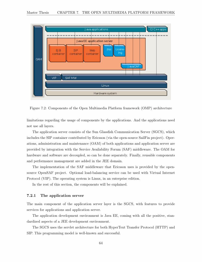
Master Thesis CHAPTER 7. THE OPEN MULTIMEDIA PLATFORM FRAMEWORK
Figure 7.2: Components of the Open Multimedia Platform framework (OMP) architecture
limitations regarding the usage of components by the applications. And the applications need
not use all layers.
The application server consists of the Sun Glassfish Communication Server (SGCS), which
includes the SIP container contributed by Ericsson (via the open-source SailFin project). Oper-
ations, administration and maintenance (OAM) of both applications and application server are
provided by integration with the Service Availability Forum (SAF) middleware. The OAM for
hardware and software are decoupled, so can be done separately. Finally, reusable components
and performance management are added in the JEE domain.
The implementation of the SAF middleware that Ericsson uses is provided by the open-
source OpenSAF project. Optional load-balancing service can be used with Virtual Internet
Protocol (VIP). The operating system is Linux, in an enterprise edition.
In the rest of this section, the components will be explained.
7.2.1 The application server
The main component of the application server layer is the SGCS, with features to provide
services for applications and application server.
The application development environment is Java EE, coming with all the positive, stan-
dardized aspects of a JEE development environment.
The SGCS uses the servlet architecture for both HyperText Transfer Protocol (HTTP) and
SIP. This programming model is well-known and successful.
64
Master Thesis CHAPTER 7. THE OPEN MULTIMEDIA PLATFORM FRAMEWORK
Using Enterprise Java Beans (EJB), the model and enterprise business logic are part of
the application server. This choice allows application to use one single process in memory for
combining business logic and communication needs.
To develop an application, there is no need to know how the SAF middleware implementation
works. All middleware services are made available through standard Java interfaces, within the
JEE Software Development kit (SDK).
7.2.2 Middleware
The middleware provides services required to build high availability applications in a clustered
system. The most important ones are:
• Availability Management Framework (AMF)
• Checkpoint service (CKPT)
• Information Model Management (IMM)
• Notification service (NTF)
The Availability Management Framework coordinates redundant resources within the clus-
ter. It also specifies an abstract system model to represent resources under its control.
The Checkpoint service manages a set of checkpoints that allow a process to save its state.
This can be used to minimize the impact of failure.
The Information Model Management allows object managers to create, access and manage
the objects of the information model.
The Notification service triggers alarms and alerts to fault management.
7.2.3 OAM
The OAM provides centralized or remote operations, administration, maintenance and provi-
sioning of OMP-based systems. OAM provides configuration management (for administering
the configuration data of a system), fault management (allows operators to detect and act on
faults) and software management (provide support for installing or upgrading support).
7.2.4 Hardware architecture
There is no need to know which type of hardware applications will be deployed on. The choice of
the hardware can be made later. However, a common hardware architecture has been defined to
ensure that the OMP components and applications can run properly. Principles and guidelines
65
Master Thesis CHAPTER 7. THE OPEN MULTIMEDIA PLATFORM FRAMEWORK
have been defined to show how applications should be built in order to reach a common view
of the underlying hardware.
This solution increases the possibility of reusing components, which was one of the initial
purposes.
7.2.5 Reuse of components
The organizations that develop applications can contribute to reusable objects. There are three
main systems to support that:
• software object inventory
• community forums
• governance structure
The software object inventory stores meta-data related to software objects. It stores candi-
dates for reusable objects, reusable objects maintained and third-party software.
The community forums share knowledge about developing applications, contain discussions
about the framework, under development software object,. . .
A council has been established to lead the development process and decide how new systems
and objects for the OMP should be developed and maintained and by whom.
7.3 Comparison between OMP framework and OSGi
In this section, a comparison will be made between OMP framework and A5350 proxy-platform
and its use of the OSGi framework. At first sight, the tools very similar in terms of aims,
advantages, layered architectures, . . . A step-by-step comparison will be made to confirm or not
this idea.
7.3.1 Generalities
There are a lot of similarities between the OMP and the A5350 (with OSGi).
The aim of both tools is to provide an execution environment for telecommunication appli-
cations, with the new requirements brought by convergence like multiprotocol support. They
provide ways to develop, deploy, manage applications easily, and encourage modularity, reuse of
components,. . . They both use Linux as operating system and Java as programming language,
two reliable open, standards, reliable and well-known tools to build applications. And Eclipse,
another open, well-known software, can be used as an Integrated Development Environment
(IDE) on both frameworks.
66
Master Thesis CHAPTER 7. THE OPEN MULTIMEDIA PLATFORM FRAMEWORK
7.3.2 Reuse of components
The reuse of component is one of the most important feature of both tools.
With OSGi, you can build bundles. These bundles export services that other bundles can
easily import. So reuse of components is extremely easy. Moreover, it is very simple to "bundle-
ize" a standard JAR file to make it available for the platform and all applications. All you have
to do is modify the Manifest of the JAR file and make it compliant with the OSGi specifications.
Usually, it takes no longer than a few minutes. This is obviously a great advantage of the A5350
and facilitates the reuse of components.
Since the OMP framework publicly provides no structure for the applications, it is hard to
know how reuse of components really works.
7.3.3 OAM
The OAM is the component that enables centralized operations of OMP-based systems. In this
way, it could be compared to the administration module of the A5350 proxy-platform. This
modules allows control and administration of the platform through several ways, including
• a web graphical user interface;
• a command line interface (allowing automated administration operations through shell
scripts, and all operations available through the web GUI);
• a Java Management Extensions (JMX) interface (used for example to have counters into
SIP Servlets);
• notifications (applications can raise notifications that can be translated into Simple Net-
work Management Protocol (SNMP) alarms);
• the Fast Cache allowing configuration, fault and configuration management
• centralized log operations (using Syslog NG) for all the ASR.
It is clear that all operations management enabled by the OAM (configuration management,
fault management, software management) are also available on the Alcatel-Lucent’s platform.
Configuration management (of the OMP framework) uses NETCONF protocol while the
ASR uses SNMP. These two protocols have the same aim, but SNMP can be considered more
mature, having more development and deployment experience.
Fault management in an OMP-based system is the function that allows operators to detect
and act on faults. This function uses SNMP. In the proxy platform, logs operations can be
centralized with Syslog NG and easily monitored. Moreover, the web GUI also allows a complete
67
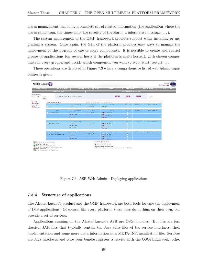
Master Thesis CHAPTER 7. THE OPEN MULTIMEDIA PLATFORM FRAMEWORK
alarm management, including a complete set of related information (the application where the
alarm came from, the timestamp, the severity of the alarm, a informative message, . . . ).
The system management of the OMP framework provides support when installing or up-
grading a system. Once again, the GUI of the platform provides easy ways to manage the
deployment or the upgrade of one or more components. It is possible to create and control
groups of applications (on several hosts if the platform is multi hosted), with chosen compo-
nents in every groups, and decide which component you want to stop, start, restart, . . .
These operations are depicted in Figure 7.3 where a comprehensive list of web Admin capa-
bilities is given.
Figure 7.3: ASR Web Admin - Deploying applications
7.3.4 Structure of applications
The Alcatel-Lucent’s product and the OMP framework are both tools for ease the deployment
of IMS applications. Of course, like every platform, these ones do nothing on their own, but
provide a set of services.
Applications running on the Alcatel-Lucent’s ASR are OSGi bundles. Bundles are just
classical JAR files that typically contain the Java class files of the service interfaces, their
implementation and some more meta information in a META-INF/manifest.mf file. Services
are Java interfaces and once your bundle registers a service with the OSGi framework, other
68

Master Thesis CHAPTER 7. THE OPEN MULTIMEDIA PLATFORM FRAMEWORK
bundles may use your "published" service.
The OMP framework is not a traditional platform but it "describes a generic execution
environment for applications that adhere to open standards"[33]. At this point, there is not a
well defined applications’ architecture but we can assume that some kinds of Java files could be
used, and why not OSGi-like bundles.
7.3.5 Conclusion
Both tools are very similar, and share a lot of features. They both encourage modularity,
reuse of components. They both are hardware independent, use Linux as the O.S., Java as
the programming language and Eclipse as the IDE,. . . But OSGi framework seems to be more
mature, with several implementations available (Apache Felix, Eclipse Equinox, FUSE ESB
4,. . . ), an active community and a lot of resources easily available on the Internet. The OMP
framework seems to be, at this point, a project still in development. Public resources are more
difficult to find, specifications seem less complete,. . .
69

Chapter 8
Conclusion
Several conclusions can be drawn from this thesis, for the RELOAD protocol itself and for its
implementation onto the A5350 proxy-platform.
Drawing final conclusions about the RELOAD protocol is not easy. When the present work
about RELOAD started (in September 2008), the protocol was still at an early stage of devel-
opment, with a single main draft, and a lot of aspects were not yet covered. Almost a year later
the situation has radically changed: there are now a lot of drafts (Working Group documents
or related documents) taking into account many aspects of the protocol. Moreover, the devel-
opment process is more and more rapid, more and more fragmented in different topics (just
like RELOAD related documents) and tracking every change in every topic becomes intricate.
This is obviously natural and inevitable, due to the complexity and the ambition of the task.
Indeed, the definition of an open, standard, "generic, self-organizing overlay network service"
is not easy and needs a lot of work.
The RELOAD protocol is bound to become the standard in the P2PSIP (and maybe P2P)
world, but some important points could be improved in order to do that. The main drawbacks
highlighted in Section 3.6 (misunderstandings, imprecisions, dependence on not mature topics
like ICE,. . . ) should be removed to allow a complete development. Moreover, some of the
RELOAD requirements could seem too heavy or complicated to set up for some uses, but
to make these requirements optional could impair interoperability. . . The question whether a
feature is mandatory or optional is very complicated to work out.
Concerning the use of RELOAD in the Alcatel-Lucent’s IMS platform, it appears that the
RELOAD protocol may be overkill the way it was initially planned. Indeed, for a specific internal
use, a dedicated, specially designed protocol with all the requirements for an industrial usage,
without useless features is more adapted. But the question of using RELOAD to exchange data
between several platforms deserves to be studied further. The question of the nature of the
information to be exchanged is open.
71

Bibliography
[1] S. Androutsellis-Theotokis and D. Spinellis, “A Survey of Peer-to-Peer Content Distribution
Technologies,” ACM Computing Surveys, vol. 36, pp. 335–371, Dec. 2004.
[2] C. Jennings, B. Lowekamp, E. Rescorla, S. Baset, and H. Schulzrinne, “REsource LO-
cation And Discovery (RELOAD) Base Protocol,” July 2009. http://tools.ietf.org/html/
draft-ietf-p2psip-base-03 (work in progress).
[3] J. Buford, H. Yu, and E. K. Lua, P2P Networking and Applications. Morgan Kaufman,
2009.
[4] I. Stoica, R. Morris, D. Liben-Nowell, D. R. Karger, M. F. Kaashoek, F. Dabek, and
H. Balakrishnan, “Chord: a scalable peer-to-peer lookup protocol for internet applications,”
IEEE/ACM Trans. Netw., vol. 11, no. 1, pp. 17–32, 2003.
[5] “Gnutella.” http://en.wikipedia.org/wiki/Gnutella, Last visited August 05, 2009.
[6] V. Pascual, V. Matuszewski, E. Shim, H. Zheng, and Y. Song, “P2PSIP Clients,” February
2008. http://tools.ietf.org/html/draft-pascual-p2psip-clients-01 (work in progress).
[7] V. Narayanan and A. Swaminathan, “Enhanced Client Support for RELOAD,” June 2009.
http://tools.ietf.org/html/draft-vidya-p2psip-eclients-00 (work in progress).
[8] S. Bradner, “Key words for use in RFCs to Indicate Requirement Levels,” 1997. http:
//tools.ietf.org/html/rfc2119.
[9] H. Song, X. Jiang, R. Even, and D. Bryan, “P2PSIP Overlay Diagnostics,” June 2009.
http://tools.ietf.org/html/draft-ietf-p2psip-diagnostics-01 (work in progress).
[10] L. Huang, “Location and Discovery of Subsets of Resources,” January 2009. http://tools.
ietf.org/html/draft-licanhuang-p2psip-subsetresourcelocation-01 (work in progress).
[11] T. Hardie and V. Narayanan, “Pointers for Peer-to-Peer Overlay Networks, Nodes, or Re-
sources,” March 2009. http://tools.ietf.org/html/draft-hardie-p2psip-p2p-pointers-01 (work
in progress).
73

Master Thesis BIBLIOGRAPHY
[12] L. Le, “Hierarchical P2PSIP Overlay,” July 2009. http://tools.ietf.org/html/
draft-le-p2psip-hierachical-p2psip-overlay-00 (work in progress).
[13] G. Li, L. Le, and N. Zhou, “Traffic localization for RELOAD,” July 2009. http://tools.ietf.
org/html/draft-li-p2psip-localization-00 (work in progress).
[14] J. Maenpaa, G. Camarillo, and J. Hautakorpi, “A Self-tuning Distributed Hash Table
(DHT) for REsource LOcation And Discovery (RELOAD),” February 2009. http://tools.
ietf.org/html/draft-maenpaa-p2psip-self-tuning-00 (work in progress).
[15] J. Mäenpää, G. Camarillo, and J. Hautakorpi, “A Self-tuning DHT for RELOAD.” IETF
proceedings, www.ietf.org/proceedings/74/slides/p2psip-0.pdf.
[16] S. Das, S. A., and V. Narayanan, “A Load Balancing Mechanism for RE-
source LOcation And Discovery,” March 2009. http://tools.ietf.org/html/
draft-saumitra-p2psip-loadbalance-00 (work in progress).
[17] J. Maenpaa, A. Swaminathan, G. Das, S. ans Camarillo, and H. J., “A Topology
Plug-in for REsource LOcation And Discovery,” July 2009. http://tools.ietf.org/html/
draft-maenpaa-p2psip-topologyplugin-00 (work in progress).
[18] V. Narayanan and A. Swaminathan, “Deterministic Replication for RELOAD,” June 2009.
http://tools.ietf.org/html/draft-vidya-p2psip-replication-00 (work in progress).
[19] L. Xiao and Y. Zhang, “A P2PSIP Client Routing for RELOAD,” May 2009. http://tools.
ietf.org/html/draft-xiao-p2psip-client-routing-00 (work in progress).
[20] J. Zhu and M. Qi, “P2PSIP Security Requirements,” February 2009. http://tools.ietf.org/
html/draft-zhu-p2psip-securityrequirements-00 (work in progress).
[21] H. Song, M. Matuszewski, and D. York, “P2PSIP Security Overview and Risk Analy-
sis,” July 2009. http://tools.ietf.org/html/draft-matuszewski-p2psip-security-requirements-05
(work in progress).
[22] Y. Mao, V. Narayanan, and A. Swaminathan, “Threat Analysis for Peer-to-Peer Over-
lay Networks,” March 2009. http://tools.ietf.org/html/draft-mao-p2psip-threat-analysis-00
(work in progress).
[23] Y. Gao and Y. Meng, “A New SIP Usage for RELOAD,” July 2009. http://tools.ietf.org/
html/draft-gaoyang-p2psip-new-sip-usage-00 (work in progress).
74
Master Thesis BIBLIOGRAPHY
[24] C. Jennings, B. Lowekamp, E. Rescorla, S. Baset, and H. Schulzrinne, “A SIP Usage
for RELOAD,” March 2009. http://tools.ietf.org/html/draft-ietf-p2psip-sip-01 (work in
progress).
[25] G. Camarillo and IAB, “Peer-to-peer (P2P) Architectures,” July 2009. http://tools.ietf.
org/html/draft-iab-p2p-archs-02.
[26] R. Cox, A. Muthitacharoen, and R. Morris, “DNS and Distributed Hash Tables Not Quite
Perfect Together.” http://swtch.com/~rsc/talks/iptps02.pdf.
[27] “The AOL XMPP scalability challenge.” http://www.process-one.net/en/blogs/article/the_
aol_xmpp_scalability_challenge.
[28] J. S. Foundation, “Extensible Messaging and Presence Protocol (XMPP): Core,” October
2004. http://tools.ietf.org/html/rfc3920.
[29] J. Wang, J. Shen, and Y. Meng, “Content Sharing Usage for RELOAD,” June 2009. http:
//tools.ietf.org/html/draft-shen-p2psip-content-sharing-00 (work in progress).
[30] “OSGi Alliance web site [online].” http://www.osgi.org, consulted August, 2009.
[31] “SIP Servlet Developer’s Homepage.” http://www1.cs.columbia.edu/~ss2020/sipservlet/,
Last visited August 2009.
[32] J. Wauthy, “P2PSIP: Towards a Decentralized, SIP-based VoIP System,” 2007.
[33] B. Andrèn, “Open Multimedia Platform framework,” Ericsson Review, no. 1, pp. 17–21,
2009.
[34] “Northbound interface.” http://en.wikipedia.org/wiki/Northbound_interface, consulted Au-
gust 14, 2009.
75


Appendix A
reload.xml file
1 <?xml version="1.0" encoding="UTF-8"?>
<!DOCTYPE reload-app>
<reload-app>
<servlet>
5 <servlet-name>ReloadServletStorage</servlet-name>
<servlet-class>
com.alcatel_lucent.reload.ReloadServletImpl
</servlet-class>
</servlet>
10 <method-mapping>
<servlet-name>ReloadServletStorage</servlet-name>
<method-name>
FETCH_REQ,FETCH_ANS,FIND_REQ,FIND_ANS,REMOVE_REQ,
REMOVE_ANS,STAT_ANS,STAT_REQ,JOIN_REQ,JOIN_ANS,
15 LEAVE_REQ,LEAVE_ANS,ROUTEQUERY_REQ,ROUTEQUERY_ANS,
PROBE_REQ,PROBE_ANS,UPDATE_REQ,UPDATE_ANS,ATTACH_REQ,
ATTACH_ANS,ATTACHLITE_REQ,ATTACHLITE_ANS,PING_REQ,
PING_ANS,STORE_REQ,STORE_ANS
</method-name>
20 </method-mapping>
</reload-app>
i


Appendix B
sip.xml file
1 <?xml version="1.0" encoding="UTF-8"?>
<!DOCTYPE sip-app PUBLIC "-//Java Community Process//
DTD SIP Application 1.0//
EN" "http://www.jcp.org/dtd/sip-app_1_0.dtd">
5 <sip-app>
<display-name>Alcatel-Lucent-SIP-Basic-Proxy</display-name>
<servlet>
<servlet-name>BasicSipServlet</servlet-name>
<servlet-class>
10 com.alcatel_lucent.examples.sip.servlet.basicproxy.BasicSipServlet
</servlet-class>
<load-on-startup/>
</servlet>
<servlet-mapping>
15 <servlet-name>BasicSipServlet</servlet-name>
<pattern>
<or>
<equal>
<var>request.method</var>
20 <value>INVITE</value>
</equal>
<equal>
<var>request.method</var>
<value>SUBSCRIBE</value>
25 </equal>
iii
Master Thesis APPENDIX B. SIP.XML FILE
<equal>
<var>request.method</var>
<value>REFER</value>
</equal>
30 <equal>
<var>request.method</var>
<value>PUBLISH</value>
</equal>
<equal>
35 <var>request.method</var>
<value>INFO</value>
</equal>
<equal>
<var>request.method</var>
40 <value>MESSAGE</value>
</equal>
</or>
</pattern>
</servlet-mapping>
45 </sip-app>
iv
