institute of technology - vvitengineeringvvitengineering.com/lab/odd/me6712-mechatronics.pdf · lab...
TRANSCRIPT

The image cannot be display ed. Your computer may not hav e enough memory to open the image, or
the image may hav e been corrupted. Restart y our computer, and then open the file again. If the red x
still appears, y ou may hav e to delete the image and then insert it again.
VARUVAN VADIVELAN
INSTITUTE OF TECHNOLOGY
DHARMAPURI-636703
LAB MANUALLAB MANUALLAB MANUALLAB MANUAL
Anna Anna Anna Anna UniversityUniversityUniversityUniversity----RRRRegulationegulationegulationegulation----2013201320132013
ME6712ME6712ME6712ME6712----MECHATRONICSMECHATRONICSMECHATRONICSMECHATRONICS LABORATORY LABORATORY LABORATORY LABORATORY
2017-2018
NAME :
REG.NO. :
SUBJECT CODE / TITLE :
DEGREE /BRANCH : _____________________________________
DEPARTMENT OF MECHANICAL ENGINEERINGDEPARTMENT OF MECHANICAL ENGINEERINGDEPARTMENT OF MECHANICAL ENGINEERINGDEPARTMENT OF MECHANICAL ENGINEERING

ME6712 - MECHATRONICS LABORATORY
OBJECTIVES
To know the method of programming the microprocessor and also the design, modeling
& analysis of basic electrical, hydraulic & pneumatic Systems which enable the students to
understand the concept of mechatronics.
LIST OF EXPERIMENTS
1. Assembly language programming of 8085 – Addition – Subtraction – Multiplication –
Division – Sorting – Code Conversion.
2. Stepper motor interface.
3. Traffic light interface.
4. Speed control of DC motor.
5. Study of various types of transducers.
6. Study of hydraulic, pneumatic and electro-pneumatic circuits.
7. Modelling and analysis of basic hydraulic, pneumatic and electrical circuits using
Software.
8. Study of PLC and its applications.
9. Study of image processing technique.
OUTCOMES
Upon completion of this course, the students can able to design mechatronics system with
the help of Microprocessor, PLC and other electrical and Electronics Circuits.
LIST OF EQUIPMENT FOR A BATCH OF 30 STUDENTS
S.NO NAME OF THE EQUIPMENT Qty
1 Basic Pneumatic Trainer Kit with manual and electrical controls/ PLC
Control each 1
2 Basic Hydraulic Trainer Kit 1
3 Hydraulics and Pneumatics Systems Simulation Software 10
4 8051 - Microcontroller kit with stepper motor and drive circuit sets 2
5 Image processing system with hardware & software 1

CONTENTS
S.No DATE NAME OF THE EXPERIMENTS PAGE
NO
STAFF
SIGN
REMARKS

MECHATRONICS
Mechatronics is the combination of Mechanical engineering, Electronic engineering,
Computer engineering, software engineering, Control engineering and Systems Design
engineering in order to design and manufacture useful products.
Mechatronics is a multi disciplinary field of engineering, that is to say it rejects
splitting engineering into separate disciplines. Originally, mechatronics just included the
combination between mechanics and electronics; hence the word is only a portmanteau
of mechanics and electronics
French standard gives the following definition: “approach aiming at the synergistic
integration of mechanics, electronics, control theory, and computer science within product design
and manufacturing, in order to improve and/or optimize its functionality".
Description
Application of mechatronics
1. Machine vision
2. Automation and robotics
The image cannot be display ed. Your computer may not hav e enough memory to open the image, or the image may hav e been corrupted. Restart y our computer, and then open the file again. If the red x still appears, y ou may hav e to delete the image and then insert it again.

3. Servo-mechanics
4. Sensing and control systems
5. Automotive engineering, automotive equipment in the design of subsystems such as anti-
lock braking systems
6. Computer-machine controls, such as computer driven machines like IE CNC milling
machines
7. Expert systems
8. Industrial goods
9. Consumer products
10. Mechatronics systems
11. Medical mechatronics, medical imaging systems
12. Structural dynamic systems
13. Transportation and vehicular systems
14. Mechatronics as the new language of the automobile
15. Diagnostic, reliability, and control system techniques
16. Computer aided and integrated manufacturing systems
17. Computer-aided design
18. Engineering and manufacturing systems
19. Packaging
20. Microcontrollers / PLC's
Ex No : 1(a) Date :
ADDITION OF TWO 8-BIT NUMBERS

AIM
To write an assembly language for adding two 8 bit numbers by using micro processor
kit.
APPARATUS REQUIRED
1. 8085 micro processor kit 8085 (0-5V)
2. DC battery
ALGORITHM
Step 1: Start the microprocessor
Step 2: Intialize the carry as ‘Zero’
Step 3: Load the first 8 bit data into the accumulator
Step 4: Copy the contents of accumulator into the register ‘B’
Step 5: Load the second 8 bit data into the accumulator.
Step 6: Add the 2 - 8 bit datas and check for carry.
Step 7: Jump on if no carry
Step 8: Increment carry if there is
Step 9: Store the added request in accumulator
Step 10: More the carry value to accumulator
Step 11: Store the carry value in accumulator
Step 12: Stop the program execution.
Address Label Mnemonics Hex Code Comments
4100 MVI C,00 OE, 00 Initialize the carry as zero

4102 LDA 4300 3A, (00, 43) Load the first 8 bit data
4105 MOV, B,A 47 Copy the value of 8 bit data
into register B
4106 LDA 4301 3A, (01, 43) Load the second 8 bit data
into the accumulator
4109 ADD B 80 Add the hoo values
410A JNC D2, 0E, 41 Jump on if no carry
410D
INR C
OC If carry is there increment it by one
410E Loop
STA 4302 32 (02, 43) Stone the added value in the
accumulator
4111 MOV A,C 79 More the value of carry to
the accumulator from
register C
4112 STA 4303 32 (03, 43) Store the value of carry in
the accumulator
4115 HLT 76 Stop the program execution
Input
Without carry
Input Address Value
4300 04
4301 02
Output
Output Address Value
4302 06
4303 00 (carry)
With carry
Input Address Value
4300 FF
4301 FF
Output Address Value
4302 FE
4303 01 (carry)

Calculation
1111 1111
1111 1111
(1) --------------------
1111 1110
===========
F E
RESULT
Thus the assembly language program for 8 bit addition of two numbers was executed
successfully by using 8085 micro processing kit.


Ex No : 1 (b) Date :
SUBTRACTION OF TWO 8 BIT NUMBERS
AIM
To write a assembly language program for subtracting 2 bit (8) numbers by using-8085
micro processor kit
APPARATUS REQUIRED
1. 8085 micro processor kit (0-5V)
2. DC battery
ALGORITHM
STEP 1: Start the microprocessor
STEP 2: Initialize the carry as ‘Zero’
STEP 3: Load the first 8 bit data into the accumulator
STEP 4: Copy the contents of contents into the register ‘B’
STEP 5: Load the second 8 bit data into the accumulator.
STEP 6: Subtract the 2 8 bit datas and check for borrow.
STEP 7: Jump on if no borrow
STEP 8: Increment borrow if there is
STEP 9: 2’s compliment of accumulator is found out
STEP 10: Store the result in the accumulator
STEP 11: More the borrow value from ‘c’ to accumulator
STEP 12: Store the borrow value in the accumulator
STEP 13: Stop program execution

Address Label Mnemonics Hex Code Comments
4100 MVI C,00 OE, 00 Initialize the carry as zero
4102 LDA 4300 3A, (00, 43) Load the first 8 bit data
4105 MOV, B,A 47 Copy the value of 8 bit data
into register B
4106 LDA 4301 3A, (01, 43) Load the second 8 bit data
into the accumulator
4109 ADD B 80 Add the hoo values
410A JNC D2, 0E, 41 Jump on if no carry
410D INR C OC If carry is there increment it
by one
410E Loop STA 4302 32 (02, 43) Stone the added value in the
accumulator
4111 MOV A,C 79 More the value of carry to
the accumulator from
register C
4112 STA 4303 32 (03, 43) Store the value of carry in
the accumulator
4115 HLT 76 Stop the program execution
Input
Without borrow
Input Address Value
4300 05
4301 07
Output Address Value
4302 02
4303 00 (borrow)
With carry

borrow
Input Address Value
4300 07
4301 05
Output Address Value
4302 02
Calculation:
05 - 07
07 -
0111
CMA 1000
ADJ
0.1 0001
----------
1001
05 - 0101
---------
1110 (-
2)
RESULT
The assembly language program subtraction of two 8 bit numbers was executed
successfully by using 8085 micro processing kit.
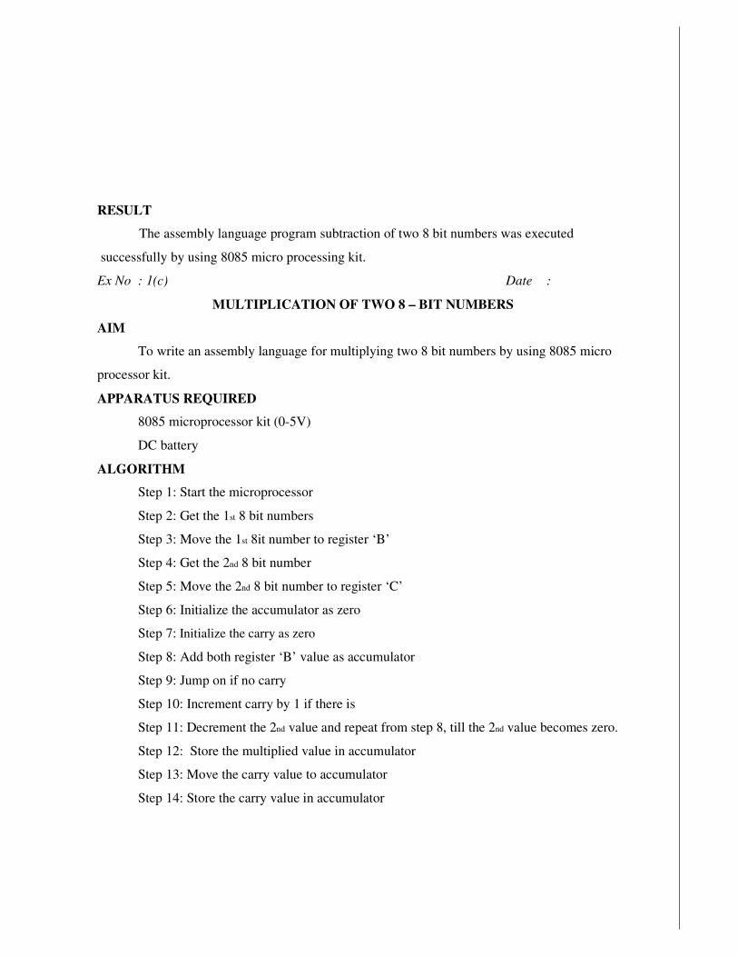
Ex No : 1(c) Date :
MULTIPLICATION OF TWO 8 – BIT NUMBERS
AIM
To write an assembly language for multiplying two 8 bit numbers by using 8085 micro
processor kit.
APPARATUS REQUIRED
8085 microprocessor kit (0-5V)
DC battery
ALGORITHM
Step 1: Start the microprocessor
Step 2: Get the 1st 8 bit numbers
Step 3: Move the 1st 8it number to register ‘B’
Step 4: Get the 2nd 8 bit number
Step 5: Move the 2nd 8 bit number to register ‘C’
Step 6: Initialize the accumulator as zero
Step 7: Initialize the carry as zero
Step 8: Add both register ‘B’ value as accumulator
Step 9: Jump on if no carry
Step 10: Increment carry by 1 if there is
Step 11: Decrement the 2nd value and repeat from step 8, till the 2nd value becomes zero.
Step 12: Store the multiplied value in accumulator
Step 13: Move the carry value to accumulator
Step 14: Store the carry value in accumulator
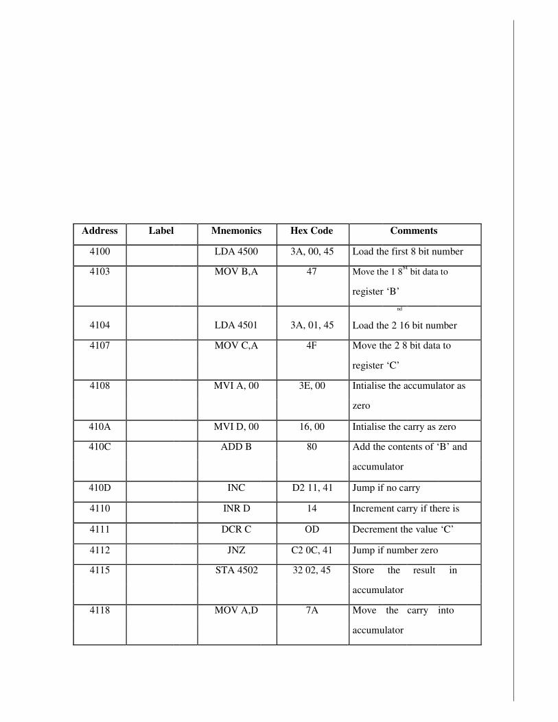
Address Label Mnemonics Hex Code Comments
4100 LDA 4500 3A, 00, 45 Load the first 8 bit number
4103 MOV B,A 47 Move the 1 8st
bit data to
register ‘B’
4104
LDA 4501 3A, 01, 45
nd
Load the 2 16 bit number
4107 MOV C,A 4F Move the 2 8 bit data to
register ‘C’
4108 MVI A, 00 3E, 00 Intialise the accumulator as
zero
410A MVI D, 00 16, 00 Intialise the carry as zero
410C ADD B 80 Add the contents of ‘B’ and
accumulator
410D INC D2 11, 41 Jump if no carry
4110 INR D 14 Increment carry if there is
4111 DCR C OD Decrement the value ‘C’
4112 JNZ C2 0C, 41 Jump if number zero
4115 STA 4502 32 02, 45 Store the result in
accumulator
4118 MOV A,D 7A Move the carry into
accumulator
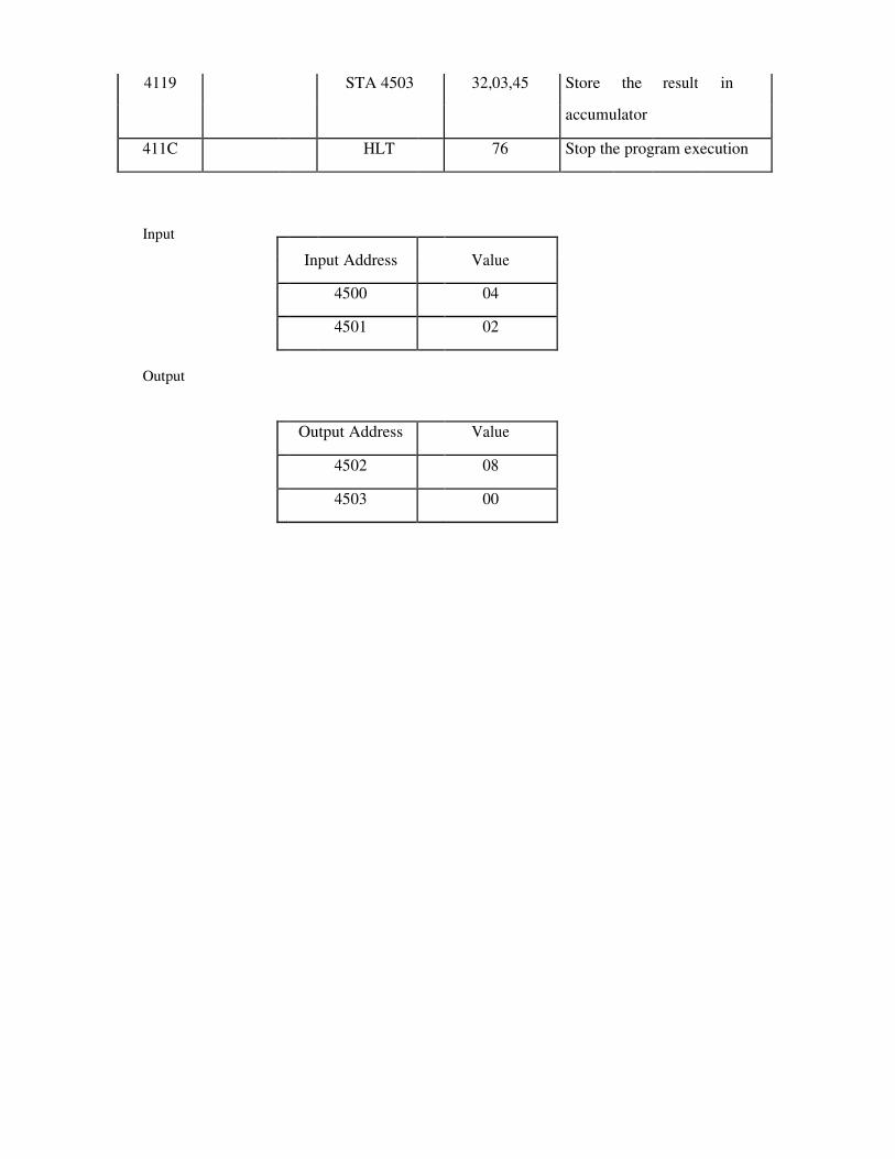
4119 STA 4503 32,03,45 Store the result in
accumulator
411C HLT 76 Stop the program execution
Input
Input Address
Value
4500 04
4501 02
Output
Output Address Value
4502 08
4503 00

RESULT
The assembly language program for multiplication of two 8 bit numbers was executed
using 8085 micro processing kit.
Ex No : 1(d) Date :
DIVISION OF TWO 8 – BIT NUMBERS
AIM
To write an assembly language program for dividing two 8 bit numbers using
microprocessor kit.
APPARATUS REQUIRED
1. 8085 microprocessor kit (0-5V)
2. DC battery
ALGORITHM
Step1: Start the microprocessor
Step2: Intialise the Quotient as zero
Step3: Load the 1st 8 bit data
Step4: Copy the contents of accumulator into register ‘B’
Step5: Load the 2nd 8 bit data
Step6: Compare both the values
Step7: Jump if divisor is greater than dividend
Step8: Subtract the dividend value by divisor value
Step9: Increment Quotient
Step10: Jump to step 7, till the dividend becomes zero
Step11: Store the result (Quotient) value in accumulator
Step12: Move the remainder value to accumulator
Step13: Store the result in accumulator
Step14: Stop the program execution
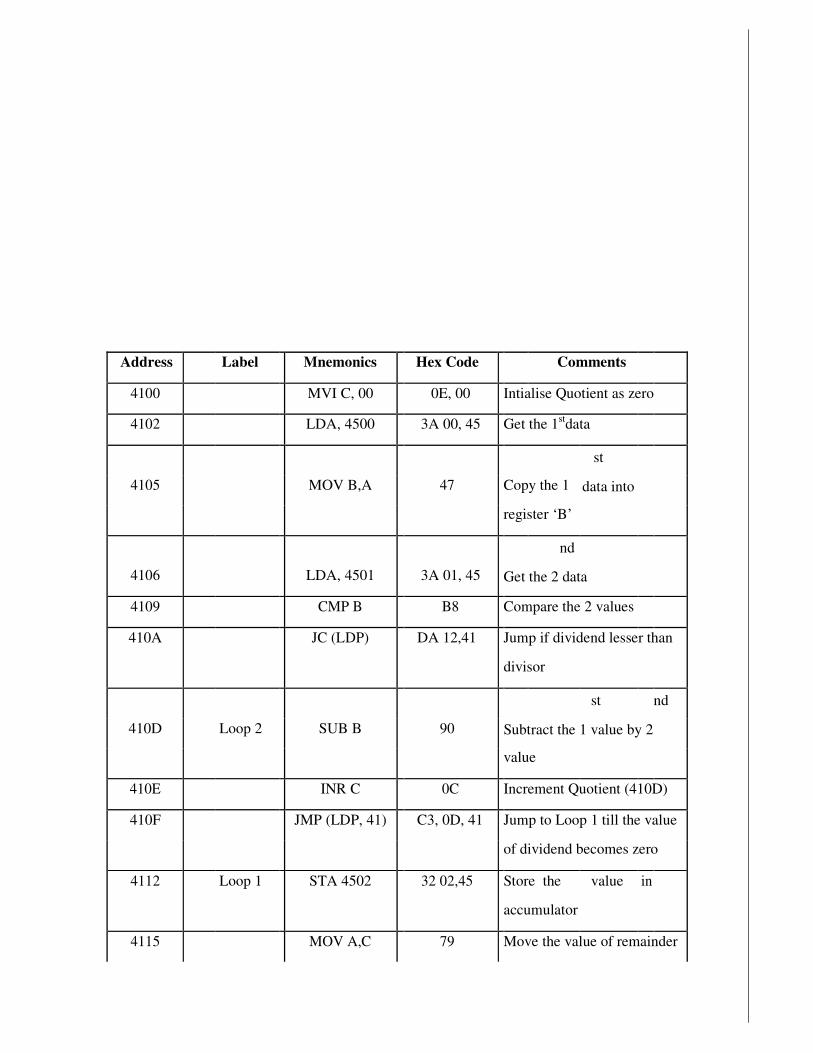
Address Label Mnemonics Hex Code Comments
4100 MVI C, 00 0E, 00 Intialise Quotient as zero
4102 LDA, 4500 3A 00, 45 Get the 1stdata
4105
MOV B,A 47
Copy the 1
st
data into
register ‘B’
4106
LDA, 4501
3A 01, 45
nd
Get the 2 data
4109 CMP B B8 Compare the 2 values
410A JC (LDP) DA 12,41 Jump if dividend lesser than
divisor
410D
Loop 2
SUB B 90
st nd
Subtract the 1 value by 2
value
410E INR C 0C Increment Quotient (410D)
410F JMP (LDP, 41) C3, 0D, 41 Jump to Loop 1 till the value
of dividend becomes zero
4112 Loop 1 STA 4502 32 02,45 Store the value in
accumulator
4115 MOV A,C 79 Move the value of remainder

to accumulator
4116 STA 4503 32 03,45 Store the remainder value in
accumulator
4119 HLT 76 Stop the program execution
Input
Input Address Value
4500 09
4501 02
Output
Output Address Value
4502 04 (quotient)
4503 01 (reminder)

RESULT
The assembly language program for division of two 8 bit numbers was executed using
8085 micro processing kit.
Ex No : 1(e) Date :
SORTING
(i) ASCENDING ORDER
AIM
To write a program to sort given ‘n’ numbers in ascending order
APPARATUS REQUIRED
8085 microprocessor kit (0-5V)
DC battery
ALGORITHM
Step1: Start the microprocessor
Step2: Accumulator is loaded with number of values to sorted and it is saved
Step3: Decrement 8 register (N-1) Repetitions)
Step4: Set ‘HL’ register pair as data array
Step5: Set ‘C’ register as counter for (N-1) repetitions
Step6: Load a data of the array in accumulator
Step7: Compare the data pointed in ‘HL’ pair
Step8: If the value of accumulator is smaller than memory, then jump to step 10.
Step9: Otherwise exchange the contents of ‘HL’ pair and accumulator
Step10: Decrement ‘C’ register, if the of ‘C’ is not zero go to step 6
Step11: Decrement ‘B’ register, if value of ‘B’ is not zero, go step 3
Step12: Stop the program execution

Address Label Mnemonics Hex Code Comments
4100 LDA 4500 3A, 00,45 Load the number of values
4103 MOV B,A 47 Move it ‘B’ register
4104 DCR B 05 For (N-1) comparisons
4105 Loop 3 LXI H, 4500 21, 00,45 Set the pointer for array
4108 MOV C,M 4E Count for (N-1) comparisons
4109 DCR C 0D For (N-1) comparisons
410A INX H 23 Increment pointer
410B Loop 2 MOV A,M 7E Get one data in array ‘A’
410C INX H 23 Increment pointer
410D CMP M BE Compare next with
accumulator
410E JC DA, 16, 41 If content less memory go
ahead
4111 MOV D,M 56 If it is greater than
interchange it
4112 MOV M,A 77 Memory content
4113 DCX H 2B Exchange the content of
memory pointed by ‘HL’ by
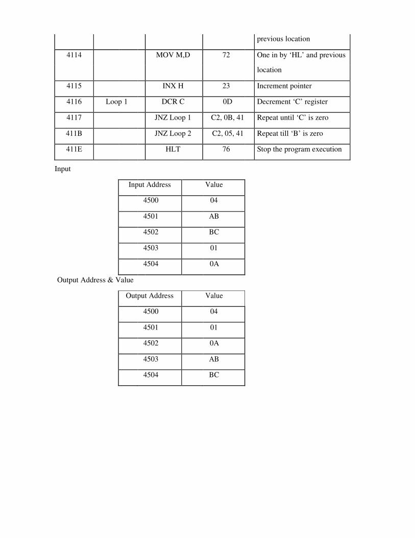
previous location
4114 MOV M,D 72 One in by ‘HL’ and previous
location
4115 INX H 23 Increment pointer
4116 Loop 1 DCR C 0D Decrement ‘C’ register
4117 JNZ Loop 1 C2, 0B, 41 Repeat until ‘C’ is zero
411B JNZ Loop 2 C2, 05, 41 Repeat till ‘B’ is zero
411E HLT 76 Stop the program execution
Input
Input Address Value
4500 04
4501 AB
4502 BC
4503 01
4504 0A
Output Address & Value
Output Address Value
4500 04
4501 01
4502 0A
4503 AB
4504 BC

RESULT
The assembly language program for sorting numbers in ascending order was executed by
microprocessor kit.
(ii) DESCENDING ORDER
AIM
To write a program to sort given ‘n’ numbers in descending order
APPARATUS REQUIRED
1. 8085 microprocessor kit (0-5V)
2. DC battery
ALGORITHM
Step 1: Start the microprocessor
Step 2: Load the number of values into accumulator and save the number of values in
register ‘B’
Step 3: Decrement register ‘B’ for (N-1) Repetitions
Step 4: Set ‘HL’ register pair as data array address pointer and load the data of array in
accumulator
Step 5: Set ‘C’ register as counter for (N-1) repetitions
Step 6: Increment ‘HL’ pair (data address pointer)
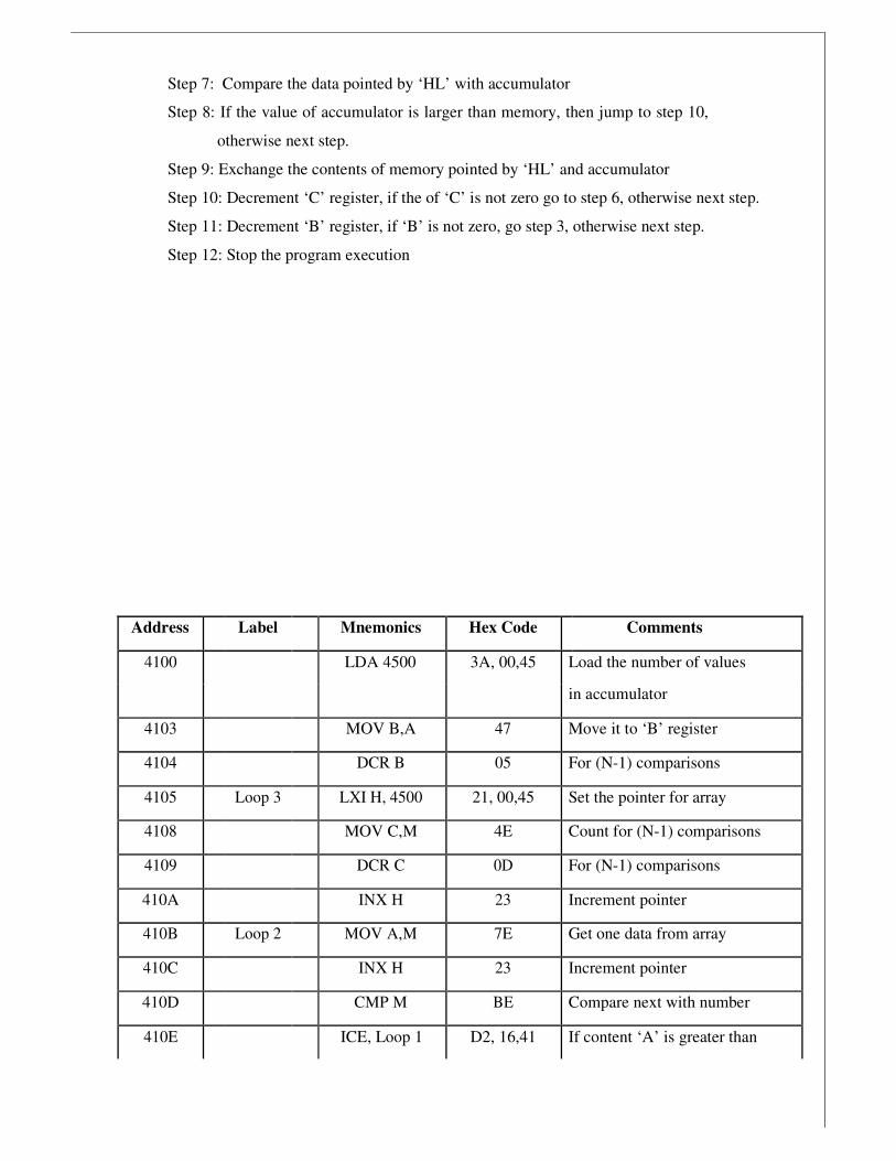
Step 7: Compare the data pointed by ‘HL’ with accumulator
Step 8: If the value of accumulator is larger than memory, then jump to step 10,
otherwise next step.
Step 9: Exchange the contents of memory pointed by ‘HL’ and accumulator
Step 10: Decrement ‘C’ register, if the of ‘C’ is not zero go to step 6, otherwise next step.
Step 11: Decrement ‘B’ register, if ‘B’ is not zero, go step 3, otherwise next step.
Step 12: Stop the program execution
Address Label Mnemonics Hex Code Comments
4100 LDA 4500 3A, 00,45 Load the number of values
in accumulator
4103 MOV B,A 47 Move it to ‘B’ register
4104 DCR B 05 For (N-1) comparisons
4105 Loop 3 LXI H, 4500 21, 00,45 Set the pointer for array
4108 MOV C,M 4E Count for (N-1) comparisons
4109 DCR C 0D For (N-1) comparisons
410A INX H 23 Increment pointer
410B Loop 2 MOV A,M 7E Get one data from array
410C INX H 23 Increment pointer
410D CMP M BE Compare next with number
410E ICE, Loop 1 D2, 16,41 If content ‘A’ is greater than

content of ‘HL’ pair
4111 MOV D,M 56 If it is greater than
interchange the datas
4112 MOV M,A 77 Accumulator to memory
value
4113 DCX H 2B Decrement memory pointer
4114 MOV M,D 72 Move the old to ‘HL’ and
previous location
4115 INX H 23 Increment pointer
4116 Loop 1 DCR C 0D Decrement ‘C’ register
4117 JNZ Loop 2 C2, 0B, 41 Repeat till ‘C’ is zero
411B JNZ Loop 3 C2, 05, 41 Jump to loop till the value of
‘B’ be
411E HLT 76 Stop the program execution
Input Address Value
4500 04
4501 AB
4502 BC
4503 01
4504 0A
Output Address & Value
Output Address Value
4500 04
4501 BC
4502 AB
4503 0A
4504 01

RESULT
The assembly language program for sorting ‘4’ numbers in descending order was
executed successfully using microprocessor kit.
Ex No : 1(f) Date :
CODE CONVERSION – DECIMAL TO HEX
AIM
To convert a given decimal number to hexadecimal
ALGORITHM
Step1. Initialize the memory location to the data pointer.
Step2. Increment B register.
Step3. Increment accumulator by 1 and adjust it to decimal every time.

Step4. Compare the given decimal number with accumulator value.
Step5. When both matches, the equivalent hexadecimal value is in B register.
Step6. Store the resultant in memory location.
PROGRAM
ADDRESS OPCODE LABEL
MNEMONICS
OPERAND
COMMENTS
8000 LXI H,8100 Initialize HL reg. to
8100H 8001
8002
8003 MVI A,00 Initialize A register.
8004
8005 MVI B,00 Initialize B register..
8006
8007 LOOP INR B Increment B reg.
8008 ADI 01 Increment A reg
8009
800A DAA Decimal Adjust Accumulator
800B CMP M Compare M & A
800C JNZ LOOP If acc and given number are
not equal, then go to LOOP 800D
800E
800F MOV A,B Transfer B reg to acc.
8010 STA 8101 Store the result in a memory
location. 8011
8012
8013 HLT Stop the program
RESULT
INPUT OUTPUT

ADDRESS DATA ADDRESS DATA
8100 8101
RESULT
Thus an ALP program for conversion of decimal to hexadecimal was written and executed.
Ex No : 1(f) Date :
CODE CONVERSION –HEXADECIMAL TO DECIMAL

AIM
To convert a given hexadecimal number to decimal.
ALGORITHM
Step1: Initialize the memory location to the data pointer. Step2:
Increment B register.
Step3: Increment accumulator by 1 and adjust it to decimal every time. Step4:
Compare the given hexadecimal number with B register value. Step5: When both
match, the equivalent decimal value is in A register. Step6: Store the resultant in
memory location.
ADDRESS OPCODE LABEL MNEMONI
CS OPERAND COMMENTS

8000 LXI H,8100 Initialize HL reg. to
8100H
8001
8002
8003 MVI A,00 Initialize A register.
8004
8005 MVI B,00 Initialize B register.
8006
8007 MVI C,00 Initialize C register for carry.
8008
8009 LOOP INR B Increment B reg.
800A ADI 01 Increment A reg
800C DAA Decimal Adjust Accumulator
800D JNC NEXT If there is no carry go to
NEXT.
800E
800F
8010 INR C Increment c register.
8011 NEXT MOV D,A Transfer A to D
8012 MOV A,B Transfer B to A
8013 CMP M Compare M & A
8014 MOV A,D Transfer D to A
8015 JNZ LOOP If acc and given number are
not equal, then go to LOOP
8016
8017
8018 STA 8101 Store the result in a memory
location.
8019
801A
801B MOV A,C Transfer C to A

801C STA 8102 Store the carry in another
memory location.
801D
801E
801F HLT Stop the program
RESULT
INPUT OUTPUT
ADDRESS DATA ADDRESS DATA
8100 8101
8102
RESULT
Thus an ALP program for conversion of hexadecimal to decimal was written and executed.
Ex No : 2 Date :
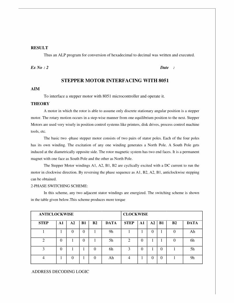
STEPPER MOTOR INTERFACING WITH 8051
AIM
To interface a stepper motor with 8051 microcontroller and operate it.
THEORY
A motor in which the rotor is able to assume only discrete stationary angular position is a stepper
motor. The rotary motion occurs in a step-wise manner from one equilibrium position to the next. Stepper
Motors are used very wisely in position control systems like printers, disk drives, process control machine
tools, etc.
The basic two -phase stepper motor consists of two pairs of stator poles. Each of the four poles
has its own winding. The excitation of any one winding generates a North Pole. A South Pole gets
induced at the diametrically opposite side. The rotor magnetic system has two end faces. It is a permanent
magnet with one face as South Pole and the other as North Pole.
The Stepper Motor windings A1, A2, B1, B2 are cyclically excited with a DC current to run the
motor in clockwise direction. By reversing the phase sequence as A1, B2, A2, B1, anticlockwise stepping
can be obtained.
2-PHASE SWITCHING SCHEME:
In this scheme, any two adjacent stator windings are energized. The switching scheme is shown
in the table given below.This scheme produces more torque
ANTICLOCKWISE CLOCKWISE
STEP A1 A2 B1 B2 DATA STEP A1 A2 B1 B2 DATA
1 1 0 0 1 9h 1 1 0 1 0 Ah
2 0 1 0 1 5h 2 0 1 1 0 6h
3 0 1 1 0 6h 3 0 1 0 1 5h
4 1 0 1 0 Ah 4 1 0 0 1 9h
ADDRESS DECODING LOGIC

The 74138 chip is used for generating the address decoding logic to generate the device
select pulses, CS1 & CS2 for selecting the IC 74175.The 74175 latches the data bus to the stepper
motor driving circuitry.
Stepper Motor requires logic signals of relatively high power. Therefore, the interface
circuitry that generates the driving pulses use silicon Darlington pair transistors. The inputs for
the interface circuit are TTL pulses generated under software control using the Microcontroller
Kit.
PROGRAMME
Address OPCODES Label Comments
4100 START: MOV DPTR, #TABLE Load the start
address of switching
4103 MOV R0, #04 Load the count in R0
4105 LOOP: MOVX A, @DPTR Load the number in
TABLE into A
4106 PUSH DPH Push DPTR value to
Stack 4108 PUSH DPL
410A MOV DPTR, #0FFC0h Load the Motor port
address into DPTR
410D MOVX @DPTR, A Send the value in A
to stepper Motor port
address
410E MOV R4, #0FFh Delay loop to cause a
specific amount of 4110 DELAY MOV R5, #0FFh
: time delay before
next data item is sent 4112 DELAY DJNZ R5, DELAY1
1: to the Motor
4114 DJNZ R4, DELAY
4116 POP DPL POP back DPTR
value from Stack

4118 POP DPH
411A INC DPTR Increment DPTR to
point to next item in
the table
411B DJNZ R0, LOOP Decrement R0, if not
zero repeat the loop
411D SJMP START Short jump to Start of
the program to make
the motor rotate
continuously
411F TABLE: DB 09 05 06 0Ah Values as per
two-phase switching
scheme
PROCEDURE
Enter the above program starting from location 4100.and execute the same. The stepper
motor rotates. Varying the count at R4 and R5 can vary the speed. Entering the data in the look-
up TABLE in the reverse order can vary direction of rotation.

RESULT
Thus a stepper motor was interfaced with 8051 and run in forward and reverse directions
at various speeds
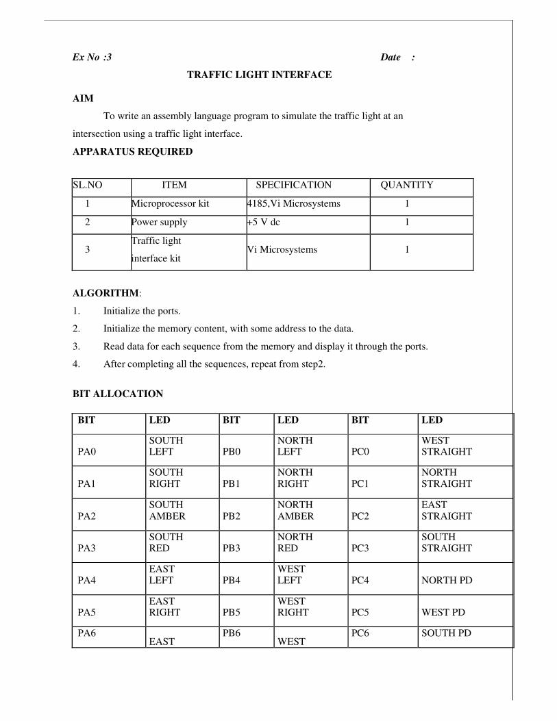
Ex No :3 Date :
TRAFFIC LIGHT INTERFACE
AIM
To write an assembly language program to simulate the traffic light at an
intersection using a traffic light interface.
APPARATUS REQUIRED
ALGORITHM:
1. Initialize the ports.
2. Initialize the memory content, with some address to the data.
3. Read data for each sequence from the memory and display it through the ports.
4. After completing all the sequences, repeat from step2.
BIT ALLOCATION
SL.NO ITEM SPECIFICATION QUANTITY
1 Microprocessor kit 4185,Vi Microsystems 1
2 Power supply +5 V dc 1
3 Traffic light
interface kit Vi Microsystems 1
BIT LED BIT LED BIT LED
PA0 SOUTH LEFT PB0
NORTH LEFT PC0
WEST STRAIGHT
PA1 SOUTH RIGHT PB1
NORTH RIGHT PC1
NORTH STRAIGHT
PA2 SOUTH AMBER PB2
NORTH AMBER PC2
EAST STRAIGHT
PA3 SOUTH RED PB3
NORTH RED PC3
SOUTH STRAIGHT
PA4 EAST LEFT PB4
WEST LEFT PC4 NORTH PD
PA5 EAST RIGHT PB5
WEST RIGHT PC5 WEST PD
PA6 EAST
PB6 WEST
PC6 SOUTH PD

CONTROL ----- 0F (FOR 8255 PPI)
PORT A ----- 0C
PORT B ----- 0D
PORT C ----- 0E
The image cannot be display ed. Your computer may not hav e enough memory to open the image, or the image may hav e been corrupted. Restart y our computer, and then open the file again. If the red x still appears, y ou may hav e to delete the image and then insert it again.
AMBER AMBER

PROGRAM
ADDRESS OPCODE LABEL MNEMONICS OPERAND COMMENT
4100 3E MVI A, 41 Move 41H immediately
to accumulator
4102 D3 OUT 0F Output contents of
accumulator to OF port
4104 REPEAT LXI H,DATA_ Load address 417B to
SQ HL
register
4107 11 LXI D,DATA_ Load address 4187 to
E DE
410A CD CALL OUT Call out address 4142
410D EB XCHG Exchange contents of
HL
410E 7E MOV A, M Move M content to
accumulator
410F D3 OUT 0D Load port A into output port
4111 CD CALL DELAY1 Call delay address
4114 EB XCHG Exchange content of
HL
4115 13 INX D Increment the content of D
4116 23 INX H Increment the content of H
4117 CD CALL OUT Call out the address
411A EB XCHG Exchange content of

HL
411B 7E MOV A, M Move M content to
accumulator
411C D3 OUT 0D Load port B into output port
411E CD CALL DELAY1 Call DELAY address
4121 EB XCHG Exchange content of
HL
4122 13 INX D Increment D register
4123 23 INX H Increment H register
4124 CD CALL OUT Call specified address
4127 EB XCHG Exchange content of
HL
4128 7E MOV A, M Move M content to
accumulator
4129 D3 OUT 0E Load port C into output port
412B CD CALL DELAY1 Call DELAY address
412E EB XCHG Exchange content of
HL
412F 13 INX D Increment D register
4130 23 INX H Increment H register
4131 CD CALL OUT Call specified address
4134 EB XCHG Exchange content of
HL
4135 7E MOV A, M Move M content to
accumulator
4136 D3 OUT 0E Load port C into output port
4138 23 INX H Increment H register
4139 7E MOV A, M Move M content to

accumulator
413A D3 OUT 0C Load port A into output port
413C CD CALL DELAY1 Call DELAY address
413F C3 JMP REPEAT Jump to specified address
4142 7E OUT MOV A, M Move M content to
accumulator
4143 D3 OUT 0E Load port C into output port
4145 23 INX H Increment H register
4146 7E MOV A, M Move M content to
accumulator
4147 D3 OUT 0D Load port B into output port
4149 23 INX H Increment H register
414B D3 OUT 0C Load port A into output port
414D CD CALL DELAY Call DELAY address
4150 C9 RET Return to accumulator
4151 E5 DELAY PUSH H Push the register H
4152 21 LXI H,001F Load 00 1F in HL register
pair
4155 01 LXI B,FFFF Load FF FF in DE register
pair
4158 0B DCX B Decrement B register
4159 78 MOV A, B Move B content to
accumulator
415A B1 ORA C OR content of C
with
415B C2 JNZ LOOP Jump to LOOP if no zero
415E 2B DCX H Decrement H register
415F 7D MOV A, L Move L content to
accumulator
RESULT
Thus an assembly language program to simulate the traffic light at an intersection using a
traffic light interfaces was written and implemented.
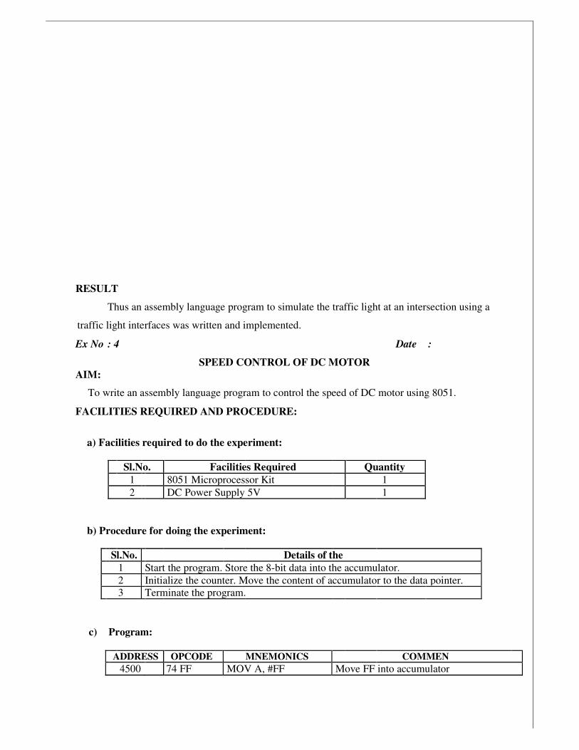
Ex No : 4 Date :
SPEED CONTROL OF DC MOTOR
AIM:
To write an assembly language program to control the speed of DC motor using 8051.
FACILITIES REQUIRED AND PROCEDURE:
a) Facilities required to do the experiment:
Sl.No. Facilities Required Quantity
1 8051 Microprocessor Kit 1
2 DC Power Supply 5V 1
b) Procedure for doing the experiment:
Sl.No. Details of the
1 Start the program. Store the 8-bit data into the accumulator.
2 Initialize the counter. Move the content of accumulator to the data pointer.
3 Terminate the program.
c) Program:
ADDRESS OPCODE MNEMONICS COMMEN
4500 74 FF MOV A, #FF Move FF into accumulator

4502 90 FF C0 MOV DPTR,#FF10H Load the value FF 10H into the data pointer
4505 F0 MOVX @DPTR,A Move the data content to the accumulator
4506 80 FF SIMPL Instruction is executed.
d) Output:
A Reg Speed Accumalator
FF High 5V
7F Medium 3V
55 Low 2V
RESULT Thus the program to control the speed of DC motor was executed and verified
successfully

The image cannot be display ed. Your computer may not hav e enough memory to open the image, or the image may hav e been corrupted. Restart y our computer, and then open the file again. If the red x still appears, y ou may hav e to delete the image and then insert it again.
Ex No : Date :
STUDY OF HYDRAULIC, PNEUMATIC AND ELECTRO PNEUMATIC CIRCUITS
AIM
To study the circuits of hydraulic, pneumatic and electro pneumatic drives.
DESCRIPTION
1. Control of a Single-Acting Hydraulic Cylinder
2. Control of a Double-Acting Hydraulic Cylinder
3. Control of single acting pneumatic cylinder
4. Control of double acting pneumatic cylinder
5. Control of single acting electro pneumatic cylinder
6. Control of double acting electro pneumatic cylinder
HYDRAULIC CIRCUITS
A hydraulic circuit is a group of components such as pumps, actuators, control valves,
conductors and fittings arranged to perform useful work. There are three important
considerations in designing a hydraulic circuit:
Control of a Single-Acting Hydraulic Cylinder

Figure shows that the control of a single-acting, spring return cylinder using a three-way
two-position manually actuated, spring offset direction-control valve (DCV). In the spring offset
mode, full pump flow goes to the tank through the pressure-relief valve (PRV). The spring in the
rod end of the cylinder retracts the piston as the oil from the blank end drains back into the tank.
When the valve is manually actuated into its next position, pump flow extends the cylinder.
After full extension, pump flow goes through the relief valve. Deactivation of the DCV
allows the cylinder to retract as the DCV shifts into its spring offset mode.

Ex No : 6 Date :
PLC CONTROL OF SINGLE ACTING CYLINDER USING AND LOGIC
AIM
Conduct the test to simulate the single acting cylinder using PLC diagram.
APPARATUS REQUIRED
1. Compressor
2. FRL
3. Air tube
4. Single acting cylinder
5. Plc
6. RS logic starter software
7. 3/2 single solenoid valve
PROCEDURE
1. Draw the circuit diagram.
2. Provide +24V and -24V from PLC trainer to electro pneumatic panel.
3. Output of the PLC is direct connect to input of 3/2 single solenoid coil.
4. Open the RS logic starter software in desktop.
5. Interface PLC with the system using RS 232 cable.
6. Following the operating procedure of RS logic starter software.
7. Connect the air supply to FRL unit.
8. Any one output of FRL unit direct connects to choosing valves.
9. Check the all circuit in panel and ladder diagram.
10. Run the PLC.
11. Observe the output.

TRUTH TABLE
INPUT OUTPUT
A B C = A * B
0 0 0
1 0 0
1 1 1
0 1 0
CIRCUIT (AND GATE)
RESULT
Thus the actuation of single acting cylinder with and AND gate was done.
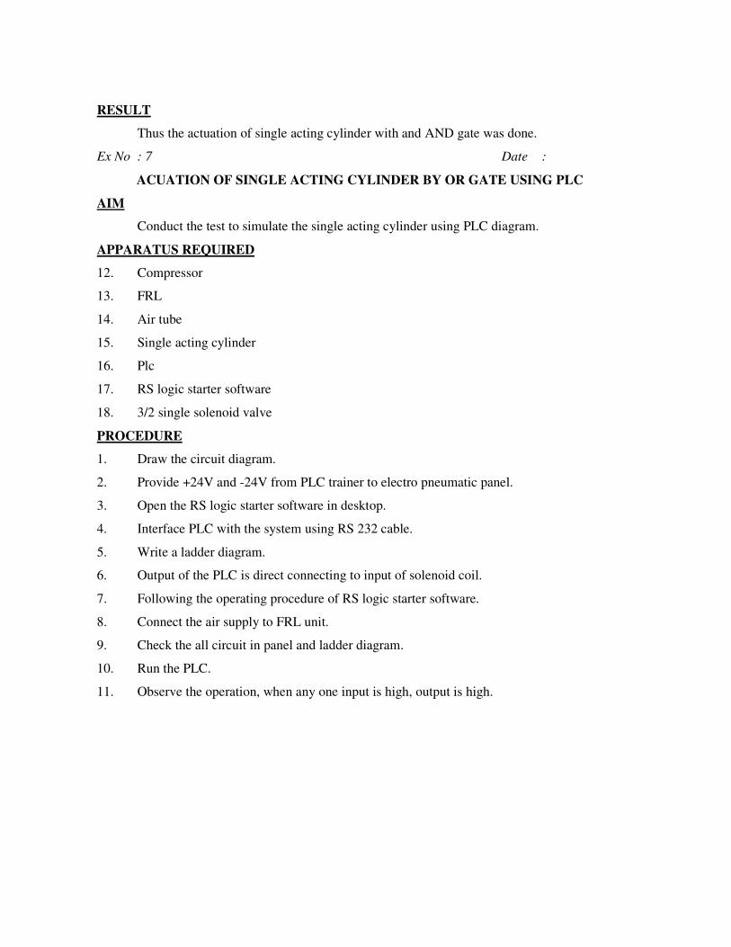
Ex No : 7 Date :
ACUATION OF SINGLE ACTING CYLINDER BY OR GATE USING PLC
AIM
Conduct the test to simulate the single acting cylinder using PLC diagram.
APPARATUS REQUIRED
12. Compressor
13. FRL
14. Air tube
15. Single acting cylinder
16. Plc
17. RS logic starter software
18. 3/2 single solenoid valve
PROCEDURE
1. Draw the circuit diagram.
2. Provide +24V and -24V from PLC trainer to electro pneumatic panel.
3. Open the RS logic starter software in desktop.
4. Interface PLC with the system using RS 232 cable.
5. Write a ladder diagram.
6. Output of the PLC is direct connecting to input of solenoid coil.
7. Following the operating procedure of RS logic starter software.
8. Connect the air supply to FRL unit.
9. Check the all circuit in panel and ladder diagram.
10. Run the PLC.
11. Observe the operation, when any one input is high, output is high.

TRUTH TABLE
INPUT OUTPUT
A B C = A+B
0 0 0
1 0 1
1 1 1
0 1 1
CIRCUIT (OR GATE)

RESULT
Thus the actuation of single acting cylinder with and OR gate was done using PLC.
Ex No : Date :
ACUATION OF SINGLE ACTING CYLINDER WITH ON DELAY TIMER
USING PLC
AIM
Conduct the test to simulate the single acting cylinder using PLC diagram.
APPARATUS REQUIRED
12. Compressor
13. FRL
14. Air tube
15. Single acting cylinder
16. Plc
17. RS logic starter software
18. 3/2 single solenoid valve
PROCEDURE:
1. Draw the circuit diagram.
2. Provide +24V and -24V from PLC trainer to electro pneumatic panel.
3. Open the RS logic starter software in desktop.
4. Interface PLC with the system using RS 232 cable.
5. Write a ladder diagram.
6. Output of the PLC is direct connecting to input of solenoid coil.
7. Following the operating procedure of RS logic starter software.
8. Connect the air supply to FRL unit.
9. Check the all circuit in panel and ladder diagram.
10. Run the PLC.
11. Observe the operation, cylinder will be actuated after given time delay.
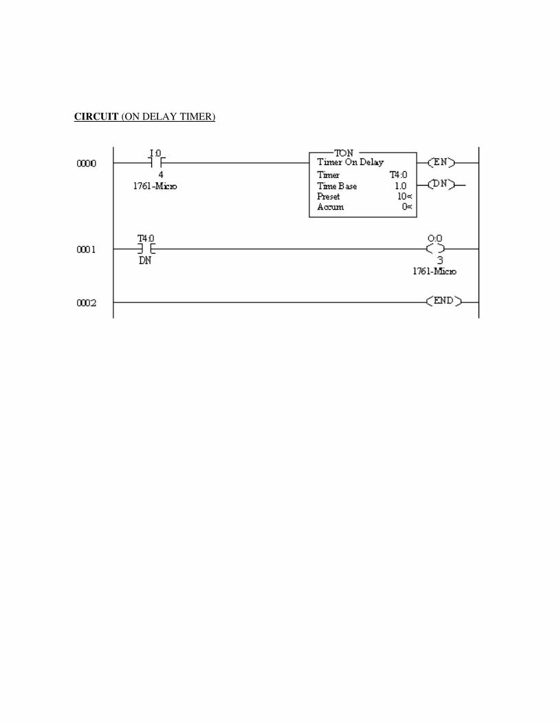
CIRCUIT (ON DELAY TIMER)

RESULT
Thus the actuation of single acting cylinder with ON Delay timer was done using PLC.
Ex No : Date :
SIMULATE THE SINGLE ACING CYLINDER WITH OFF DELAY
TIMER USING PLC AIM
Conduct the test to simulate the single acting cylinder using PLC diagram.
APPARATUS REQUIRED
12. Compressor
13. FRL
14. Air tube
15. Single acting cylinder
16. Plc
17. RS logic starter software
18. 3/2 single solenoid valve
PROCEDURE
1. Draw the circuit diagram.
2. Provide +24V and -24V from PLC trainer to electro pneumatic panel.
3. Open the RS logic starter software in desktop.
4. Interface PLC with the system using RS 232 cable.
5. Write a ladder diagram.
6. Output of the PLC is direct connecting to input of solenoid coil.
7. Following the operating procedure of RS logic starter software.
8. Connect the air supply to FRL unit.
9. Check the all circuit in panel and ladder diagram.
10. Run the PLC.
11. Observe the operation; cylinder goes to off position after particular time delay added.

CIRCUIT (OFF DELAY TIMER)
RESULT
Thus the actuation of single acting cylinder with OFF Delay timer was done using PLC.
Ex No : Date :
CONTROL OF DOUBLE ACTING CYLINDER WITH UP COUNTER USING PLC
AIM
Conduct the test to control the double acting cylinder with up counter using PLC
diagram.
APPARATUS REQUIRED
12. Compressor
13. FRL
14. Air tube
15. Single acting cylinder
16. Plc
17. RS logic starter software
18. 3/2 single solenoid valve
PROCEDURE:
1. Draw the circuit diagram.
2. Provide +24V and -24V from PLC trainer to electro pneumatic panel.
3. Open the RS logic starter software in desktop.
4. Interface PLC with the system using RS 232 cable.
5. Write a ladder diagram.
6. Output of the PLC (q1) is direct connecting to input of solenoid coil.
7. Following the operating procedure of RS logic starter software.
8. Connect the air supply to FRL unit.
9. Check the all circuit in panel and ladder diagram.
10. Run the PLC program
11. Cylinder will run continuously as ON, OFF with preset value in counter.

CIRCUIT (UP COUNTER)
The image cannot be display ed. Your computer may not hav e enough memory to open the image, or the image may hav e been corrupted. Restart y our computer, and then open the file again. If the red x still appears, y ou may hav e to delete the image and then insert it again.

RESULT
Thus the actuation of double acting cylinder completed with up counter using PLC.
Ex No : Date :
AUTOMATIC ACTUATION OF SINGLE ACTING CYLINDER USING PLC
AIM
Conduct the test to simulate the automatic sequence of single acting cylinder using PLC.
APPARATUS REQUIRED
12. Compressor
13. FRL
14. Air tube
15. Single acting cylinder
16. Plc
17. RS logic starter software
18. 3/2 single solenoid valve
PROCEDURE:
1. Draw the circuit diagram.
2. Provide +24V and -24V from PLC trainer to electro pneumatic panel.
3. Open the RS logic starter software in desktop.
4. Interface PLC with the system using RS 232 cable.
5. Write a ladder diagram.
6. Output of the PLC (q1) is direct connecting to input of solenoid coil.
7. Following the operating procedure of RS logic starter software.
8. Connect the air supply to FRL unit.
9. Check the all circuit in panel and ladder diagram.
10. Run the PLC program
11. Observe the working of single acting cylinder is automatic reciprocating.

CIRCUIT (Automatic Actuation Of Single Acting Cylinder)

RESULT
Thus the actuation of automatic sequence of single acting cylinder completed using PLC.

Ex No : Date :
AUTOMATIC ACTUATION OF DOUBLE ACTING CYLINDER USING PLC
AIM
Conduct the test to simulate the automatic sequence of double acting cylinder using PLC.
APPARATUS REQUIRED
12. Compressor
13. FRL
14. Air tube
15. Single acting cylinder
16. Plc
17. RS logic starter software
18. 3/2 single solenoid valve
PROCEDURE:
1. Draw the circuit diagram.
2. Provide +24V and -24V from PLC trainer to electro pneumatic panel.
3. Open the RS logic starter software in desktop.
4. Interface PLC with the system using RS 232 cable.
5. Write a ladder diagram.
6. Output of the PLC (q1) & (q2)is direct connecting to input of solenoid coil.
7. Following the operating procedure of RS logic starter software.
8. Connect the air supply to FRL unit.
9. Check the all circuit in panel and ladder diagram.
10. Run the PLC program
11. Observe the working of double acting cylinder is automatic reciprocating.

CIRCUIT (Automatic Actuation Of Double Acting Cylinder)
RESULT

Thus the actuation of automatic sequence of double acting cylinder completed using
PLC.
Ex No : Date :
PLC CONTROL OF SEQUENCING CIRCUIT USING PLC LADDER DIAGRAM
AIM
Conduct the test to run a circuit for the sequence A+B+A-B- using PLC
APPARATUS REQUIRED
12. Compressor
13. FRL
14. Air tube
15. Double acting cylinder
16. Mini actuate cylinder
17. PLC
18. RS logic starter software
19. 3/2 single solenoid valve
PROCEDURE:
1. Draw the circuit diagram.
2. Provide +24V and -24V from PLC trainer to electro pneumatic panel.
3. Open the RS logic starter software in desktop.
4. Interface PLC with the system using RS 232 cable.
5. Write a ladder diagram.
6. Both outputs of PLC (q1,q2, q3,q4) are directly connected to inputs of solenoid coils.
7. Following the operating procedure of RS logic starter software.
8. Connect the air supply to FRL unit.
9. Check the all circuit in panel and ladder diagram.
10. Run the PLC program
11. Observe the working of double acting cylinder is automatic reciprocating using the circuit
A+B+A-B-

OBSERVATION
In this electro pneumatic circuit the push button FWR 1 and FWD2 both are actuate only
the solenoid coil s1will be energized the double acting cylinder rod will be extracted. If the any
one of this push button will press the solenoid coil s1 could not energized and then the cylinder
rod should not extracted.
The image cannot be display ed. Your computer may not hav e enough memory to open the image, or the image may hav e been corrupted. Restart y our computer, and then open the file again. If the red x still appears, y ou may hav e to delete the image and then insert it again.

OBSERVATION
In this electro pneumatic circuit the push button FWR 1, FWR 2 any one of this push
button we should press then only the solenoid coil s1will be energized the double acting cylinder
rod will be extracted. If both of this push button will press the solenoid coil s1 could not
energized and then the cylinder rod should not extracted.
RESULT

The ladder diagram for the automatic running of double acting cylinder is using this
circuit A+B+A-B-.is designed and executed.
Ex No : Date :
CONTROLLING THE SINGLE ACTING CYLINDER USING PUSH BUTTON
SWITCH
AIM
To construct a pneumatic circuit to control the single acting cylinder using push button
switch.
APPARATUS REQUIRED
12. Compressor
13. FRL
14. Air tube
15. Single acting cylinder
16. Batch card
PROCEDURE
1. Draw the circuit diagram.
2. Electro controller gives –ve voltage to pneumatic panel.
3. Input of push button is getting from solenoid valve output.
4. Connect the air supply to FRL unit.
5. Check all the connections carefully
6. Test the circuit.
7. Observe the working of the cylinder using the 3/2 single solenoid valve.

RESULT
Thus the movement of single acting cylinder was carried out using the 3/2 single solenoid
valve.
Ex No : Date :
CONTROLLING DOUBLE ACTING CYLINDER USING PUSH BUTTON SWITCH
AIM
To construct a pneumatic circuit to control the double acting cylinder using push button
switch.
APPARATUS REQUIRED
8. Compressor
9. FRL
10. Air tube
11. 5/2 double solenoid valve
12. Double acting cylinder
13. Batch card
14. Electrical controller
PROCEDURE
1. Draw the circuit diagram and connect the air supply to FRL unit.
2. Provide power supply to the pneumatic trainer from control trainer by interfacing 24V +
and –
3. Input of push button is getting from solenoid valve output.
4. Check all the connections carefully
5. Test the circuit.
6. When the solenoid is given a signal by a push button switch. DCV is activated to double
acting cylinder.
7. When off button is pressed the signal solenoid are cut and the solenoids are de-energized
and the DCV comes to the original position.
RESULT
Thus the movement of double acting cylinder was carried out using the 5/2 double
solenoid valve.
Ex No : Date :
CONTROLLING DOUBLE ACTING CYLINDER THROUGH SPDT SWITCH
AIM
To construct a pneumatic circuit to control the single acting cylinder using push button
switch.
APPARATUS REQUIRED
8. Compressor
9. FRL
10. Air tube
11. 5/2 double solenoid valve
12. Double acting cylinder
13. Batch card
14. Electrical controller
PROCEDURE
1. Draw the circuit diagram.
2. Provide power supply to the pneumatic trainer from control trainer by interfacing 24V +
and –
3. Using the SPDT switch energize the corresponding solenoid valve to get the desired
movement in the cylinder.
4. Supply the air to FRL unit.
5. Electro controller gives –ve voltage to pneumatic panel.
6. Input of push button is getting from solenoid valve output.
7. Connect the air supply to FRL unit.
8. Check all the connections carefully
9. Test the circuit.
10. Observe the working of the cylinder using the 3/2 single solenoid valve.
RESULT
Thus the movement of double acting cylinder was carried out using the 5/2 double
solenoid valve.
Ex No : Date :
ACTUATION OF SINGLE ACTING CYLINDER USING ON DELAY TIMER
AIM
Develop an electro pneumatic circuit to control the single acting cylinder through timer.
APPARATUS REQUIRED
11. Compressor
12. FRL
13. Air tube
14. 5/2 double solenoid valve
15. Double acting cylinder
16. Batch card
17. Electrical controller
PROCEDURE
1. Draw the circuit diagram.
2. Provide power supply to pneumatic trainer from electrical controller by interfacing the
+ve & -ve.
3. Using the SPDT switch energize the corresponding solenoid to get the desired movement
of the cylinder.
4. Actuate the time delay circuit.
5. From time delay give connection to single along cylinders according to time set.
6. Design and draw the pneumatic circuit.
7. Connect the air supply.
8. Test the circuit.
9. Observe the working of the cylinder

RESULT
Thus the movement of single acting cylinder was carried out using time delay.
Ex No : Date :
CONTINUOUS ACTUATION OF DOUBLE ACTING CYLINDER USIN MAGNETIC
PROXIMITY SENSOR
AIM
Construct a pneumatic circuit to control the double acting cylinder electrically using
magnetic proximity sensor.
APPARATUS REQUIRED
10. Compressor
11. FRL
12. Air tube
13. 5/2 double solenoid valve
14. Double acting cylinder
15. Batch card
16. Electrical controller
17. sensors
PROCEDURE
1. Draw the circuit diagram.
2. Connect the circuit diagram in all components.
3. Connect air supply to FRL unit.
4. Connect the electrical circuit from electrical controller to panel (24+ and 24-)
5. Connect proximity sensors output to 5/2 double solenoid valve input.
6. Check all circuit in panel.
7. Test the circuit
8. Observe the working in double acting cylinder activated.

RESULT
Thus the movement of double acting cylinder was carried out using the magnetic
proximity sensor.
Ex No : Date :
CONTROLLING PRESSURE VARIABLE THROUGH PID CONTROLLER
AIM
Conduct the test to observe the performance of PID controller on Pressure Process.
APPARUTUS REQUIRED
1. VMPA-62A
2. VDPID-03
3. PC with process control and Lab View software.
4. Patch chords
5. RS 232 cable and loop cable.
HAND VALVE SETTINGS
HV1 - Fully Open
HV2 - Fully Open
HV3 - Fully Close
HV4 - Partially Open
PRESSURE RANGE
Input - 0 to 250 mm WC
Output - 4 to 20 mA
PROCEDURE
1. Ensure the availability of water.
2. Interface the digital controller with process and PC.
3. Make the connection as per connection diagram.
4. Ensure hand valve settings are correct.
5. Switch ON VMPA-62A unit and digital controller with PC.
6. Invoke process control software or lab view software.
7. Select pressure PID.

8. Heater/Pump ON switch should be in pump mode.
9. Enter the parameters and observe the response of various controllers at various set points.
10. Stop the process.
11. Save the response and conclude the behavior of pressure process.
TABULATION
S.No Time in (sec) Pressure in(N/mm2)

RESULT
Thus the performance of the PID controller on pressure process was studied.
Ex No : Date :
CONTROLLING FLOW VARIABLE THROUGH PID CONTROLLER
AIM
Conduct the test to observe the performance of PID controller on Flow Process.
APPARUTUS REQUIRED
1. VMPA-62A
2. VDPID-03
3. PC with process control and Lab View software.
4. Patch chords
5. RS 232 cable and loop cable.
HAND VALVE SETTINGS
HV1 - Fully Open
HV2 - Fully Open
HV3 - Fully Close
HV4 - Fully Open
FLOW RANGE
Input - 50 to 500 LPH
Output - 4 to 20 mA DC
PROCEDURE
1. Ensure the availability of water.
2. Interface the digital controller with process and PC.

3. Make the connection as per connection diagram.
4. Ensure hand valve settings are correct.
5. Switch ON VMPA-62A unit and digital controller with PC.
6. Invoke process control software or lab view software.
7. Select Flow PID.
8. Heater/Pump ON switch should be in pump mode.
9. Enter the parameters and observe the response of various controllers at various set points.
10. Stop the process.
11. Save the response and conclude the behavior of Flow process.
TABULATION
S.NO TIME
(sec)
FLOW
(LPH)

RESULT
Thus the performance of the PID controller on Flow process was studied.
Ex No : Date :
CONTROLLING TEMPERATURE VARIABLE THROUGH PID CONTROLLER
AIM
Conduct the test to observe the performance of PID controller on Temperature Process.
APPARUTUS REQUIRED
1. VMPA-62A
2. VDPID-03
3. PC with process control and Lab View software.
4. Patch chords
5. RS 232 cable and loop cable.
HAND VALVE SETTINGS
HV1 - Partially Open
HV2 - Fully Close
HV3 - Fully Open
TEMPERATUR RANGE
Input - 0 to 100ºc
Output - 4 to 20 mA DC
PROCEDURE
1. Ensure the availability of water.
2. Interface the digital controller with process and PC.
3. Make the connection as per connection diagram.
4. Ensure hand valve settings are correct.
5. Switch ON VMPA-62A unit and digital controller with PC.
6. Invoke process control software or lab view software.

7. Select temperature PID.
8. Heater/Pump ON switch should be in pump mode.
9. Enter the parameters and observe the response of various controllers at various set points.
10. Stop the process.
11. Save the response and conclude the behavior of pressure process.

RESULT
Thus the performance of the PID controller on Temperature Process was studied.
Ex No : Date :
DESIGN AND TESTING FOR ACTUATION OF HYDRUALIC CYLINDER TO FIND
OUT FORCE Vs PRESSURE
AIM
To actuate the hydraulic cylinder and find out the force Vs pressure.
APPARATUS REQUIRED
1. Oil tank
2. Single phase motor
3. Pressure relief valve
4. 4/3 double acting solenoid valve
5. Double acting cylinder
6. Load cell
7. Data activation card than lab view software.
PROCEDURE
1. Switch on the electrical power supply with motor.
2. Switch on the power supply to the control unit
3. Open the lab view software in the system.
4. Interface hydraulic trainer with system using RS-232
5. Open the force, go to operate, click the run then power on
6. Now extend the system by pressing the up button.
7. Load cell indicates the force value in the monitor.
8. Now adjust the pressure regulator and set the maximum pressure as 25 Kg/cm2
9. Retract the cylinder.
10. Once again forward the cylinder; you have adjusted the pressure in pressure regulator.
11. You have seen the force in monitoring

12. Repeat the force value for different pressure.
TABULATION
S.No Pressure in Kg/cm2 Displayed force in Kg Calculate force in Kg % of errors
CALCULATION
(a) PRESSURE=�����
���� Kg/Cm
2
(b) AREA=�.� !"
# $² Cm
2
D- Cylinder diameter
Cylinder diameter=40mm
Cylinder rod diameter=30mm
Cylinder stroke length= 150mm
(C) % of Error= &'()*+,-. /012-3�+*24*+5-. /012-
&'()*+,-. /012-X 10
MODEL CALCULATION

RESULT
The Actuation of Hydraulic Cylinder Was Carried Out.
Ex No : Date :
DESIGN AND TESTING FOR ACTUATION OF HYDRUALIC CYLINDER TO FIND
OUT SPEED Vs DISCHARGE
AIM
To actuate the hydraulic cylinder and find out the Speed Vs Discharge.
APPARATUS REQUIRED
1. Oil tank
2. Single phase motor
3. Gear pump.
4. Pressure relief valve
5. 4/3 double acting solenoid valve
6. Flow control valve.
7. Double acting cylinder
8. Load cell
9. Data activation card than lab view software.
PROCEDURE
10. Switch on the electrical power supply with motor.
11. Switch on the power supply to the control unit
12. Open the lab view software in the system.
13. Interface hydraulic trainer with system using RS-232
14. Open the speed, go to operate, click the run then power on
15. Now regulate the flow control valve contract the system by pressing down position. After
seen monitor in velocity cm/sec.
16. Now regulate the flow control valve and set the maximum flow to find the up and
velocity
17. Repeat the velocity values for different flows.

TABULATION
S.no Velocity in Up
(Cm/Sec)
Velocity in Down
(Cm/Sec)
Discharge in Up
(Lits/Sec)
Discharge in Down
(Lits/Sec)
CALCULATION
(a)Velocity (Speed) =�7�8
���� Cm/ Sec
(b)AREA=9
# $² Cm
2
Flow = Discharge (Q) in lits/sec
Flow =Velocity x Area
MODEL CALCULATION
RESULT
The Actuation of Hydraulic Cylinder Was Carried Out.
Ex No : Date :
SERVO CONTROLLER INTERFACING FOR OPEN LOOP SYSTEM
AIM
To study the performance of open loop by using servo motor.
COMPONENTS REQUIRED
1. AC Servo motor
2. PLC
3. WINPRO Ladder software
4. Pc, connecting cable
5. Patch card
PROCEDURE
OPEN LOOP SYSTEM
1. Load the WIN Pro ladder software in Pc
2. Open the PLC trainer
3. Connect the PLC servo controller kit
4. Open the new folder and draw the ladder logic diagram.
5. Connect drive and Pc.
6. Set the speed and direction and other drives
7. Connect the PLC and Pc and run the program.
CIRCUIT DIAGRAM

OBSERVATION
In the open loop circuit we design function for run the AC servo motor and the control
the speed or positions. We give that input command 200 rpm or 230 ̊angle. In the input
commands the open loop system act not accurate because the some error signals occurred due to
some voltage deviations. So the output of the open loop system is not accurate.
TABULATION:
S.No INPUT SPEED
(rpm)
OUTPUT SPEED
(measured by tachometer)
(rpm)
ERROR %
1 230 220 4.5
2 300 280 7.1
3 500 485 3
The image cannot be display ed. Your computer may not hav e enough memory to open the image, or the image may hav e been corrupted. Restart y our computer, and then open the file again. If the red x still appears, y ou may hav e to delete the image and then insert it again.

RESULT
Thus the performance for AC servo motor was studied for open loop system.
Ex No : Date :
SERVO CONTROLLER INTERFACING FOR CLOSED LOOP SYSTEM
AIM
To study the performance of closed loop by using servo motor.
COMPONENTS REQUIRED
1. AC Servo motor
2. PLC
3. WINPRO Ladder software
4. Pc, connecting cable
5. Patch card
PROCEDURE
CLOSED LOOP SYSTEM
1. Load the WIN Pro ladder software in Pc
2. Open the PLC trainer
3. Connect the PLC and servo controller unit.
4. Logic diagram
5. Connect the drive and Pc
6. Run the program.
CIRCUIT DIAGRAM

OBSERVATION
In the closed loop system we control the AC motor speed as well as position. In the
closed loop system control’s output signals based on feedback device. In the feedback device is
connected in to the output side to input comparator side. So in this closed loop system reduces
the error signals based on the feedback device and then the output will more accurate.
TABULATION
The image cannot be display ed. Your computer may not hav e enough memory to open the image, or the image may hav e been corrupted. Restart y our computer, and then open the file again. If the red x still appears, y ou may hav e to delete the image and then insert it again.
S.No INPUT SPEED
(rpm)
OUTPUT SPEED
(measured by tachometer)
(rpm)
ERROR %
1 230 229.5 0.21
2 300 300 0
3 500 500 0

RESULT
Thus the performance for AC servo motor was studied for closed loop system.