instapatch optical tap modules - commscope · issue 2, may 2014 instapatch® optical tap modules...
TRANSCRIPT

860572908 Issue 2, May 2014 www.commscope.com
InstaPATCH® Optical Tap Modules
General The InstaPATCH® optical tap modules are available for both multimode and singlemode applications and have either 12 or 24 LC adapters on the front and either 2 or 4 MPO adapters on the rear. The modules are also available in various split ratios. The split ratio refers to the amount of optical energy that travels directly from input to output versus the amount that is diverted from the main channel to the tap output. InstaPATCH optical tap modules are available in 70/30 and 50/50 ratios
Ordering information for the tap modules is listed below:
Material ID Part No. Description 760188284 360TM-12LC-LS-70:30 Optical tap module, 12 LC ports, multimode, 70/30 split 760188292 360TM-12LC-LS-50:50 Optical tap module, 12 LC ports, multimode, 50/50 split 760188300 360TM-12LC-SM-70:30 Optical tap module, 12 LC ports, singlemode, 70/30 split 760188318 360TM-12LC-SM-50:50 Optical tap module, 12 LC ports, singlemode, 50/50 split 760188607 360TM-24LC-LS-70:30 Optical tap module, 24 LC ports, multimode, 70/30 split 760188615 360TM-24LC-LS-50:50 Optical tap module, 24 LC ports, multimode, 50/50 split 760188623 360TM-24LC-SM-70:30 Optical tap module, 24 LC ports, singlemode, 70/30 split 760188631 360TM-24LC-SM-50:50 Optical tap module, 24 LC ports, singlemode, 50/50 split
Figure 1. InstaPATCH® Optical Tap Modules (12 and 24 LC Multimode Shown)
© 2014 CommScope, Inc. All rights reserved
Page 1 of 11

860572908 Instruction Sheet
www.commscope.com
How to Contact Us
• To find out more about CommScope® products, visit us on the web at http://www.commscope.com/
• For technical assistance:
- Within the United States, contact your local account representative or technical support at 1-800-344-0223. Outside the United States, contact your local account representative or PartnerPRO™ Network Partner.
- Within the United States, report any missing/damaged parts or any other issues to CommScope Customer Claims at 1-866-539-2795 or email to [email protected]. Outside the United States, contact your local account representative or PartnerPRO Network Partner.
Tools and Materials Required The following tools and materials are required for testing:
• (1) Light source*
• (2) Power meters*
• (2) LC-to-LC jumpers
• (1) LC-to-LC adapter
• (1) LC-to-MPO fanout (360TM array fanout)
WARNING – Important Safety Instructions
Laser Precautions WARNING: DO NOT use microscopes or other optical magnification or look directly into without first verifying that the device under inspection does not contain laser light. Laser light can cause eye damage or damage to inspection equipment. Never look directly into the end of a connector that may be carrying laser light. Should accidental eye exposure to laser light be suspected, seek medical attention immediately.
Cabling Precautions Fiber optic cable assemblies are sensitive to loading, bending, twisting and crushing in excess of recommendations. Do not exceed minimum bend radii recommendations or the cable may be damaged and require repair or replacement. Use proper strain relief techniques to prevent cable loading from being transferred to equipment or modules.
Module Precautions Modules are designed to withstand normal operating conditions. Modules are not designed to withstand excessive loading or impact. Use dust caps or shutters to limit the amount of particulate contamination to the connector end faces. If cleaning is necessary, follow the instructions outlined in CommScope ST, SC, LC, and MPO Connectors instruction sheet 700074628.
* Power meters and light source shown in diagrams are courtesy of FLUKE® Corporation.
Page 2 of 11

www.commscope.com 860572908 Instruction Sheet
Design of the Optical Tap Link
Overview The splitters inside an optical tap module divert a predictable amount of optical energy from the received optical signal to an output port. InstaPATCH optical tap modules are available in 70/30 and 50/50 ratios (for example, a 70/30 module has 70% of the main input passing through to the main output, with 30% diverted to the tap output).
The “A” LC connectors of each duplex LC port in a tap module serve as input and their signals are split between the MAIN and TAP MPO output ports.
Similarly, the optical tap module “B” LC connectors serve as output and receive their signals from the split traffic from the MAIN input MPO along with diverted signals being routed to the TAP MPO output port.
Directionality Optical tap modules must be tested with directionality in mind i.e. careful consideration of whether a port is input or output must be performed and followed when designing the link and testing. The modules contain splitters, which are physical devices used to obtain the diversion of optical energy. Splitters are directional i.e. it matters which direction the optical energy enters the module and proceeds through the splitter.
Position of Tap Module within the Link The inherent function of the optical tap module (diverting a predictable amount of the energy to a port for secondary use) will serve to reduce the amount of power available along the MAIN link. In addition, where the module is placed within the link will affect how much actual power is available. A module placed at the beginning of a link will yield a lesser amount of power at the far end of the link along the main channel as compared to a module placed at the end of a link for one of the fibers within a transmit/receive pair. As a result, analysis must be performed on the loss budget and allocation within the channel to determine the best placement, along with considerations of transceiver specification and performance.
Wavelength Considerations The splitters on multimode modules are optimized for 850nm wavelength; thus, when testing multimode systems, use only the 850nm wavelength. Singlemode systems are optimized for 1310nm; thus, when testing singlemode systems, use the 1310nm wavelength.
Calculating System Loss Budgets The SYSTIMAX® Link Loss Calculator includes inputs for the InstaPATCH optical tap module (Revision 7.0 or higher). Using the Link Loss Calculator (which utilizes standards-based calculation methods) will provide accurate predictions of loss budgets.
Installing an InstaPATCH Optical Tap Module Tap module installation, trouble shooting, and other module-related topics are covered here. Close attention should be given to handling of the modules and cleaning of the interfaces.
Install the tap module and its 360TM array fanout per the individual link design. Pay close attention to whether the tap module is in ALPHA or BETA orientation as the tap array fanout will be a corresponding configuration. Note that the tap array fanout is strictly output and does not exhibit transmit/receive behavior.
Page 3 of 11

860572908 Instruction Sheet
www.commscope.com
12-Fiber Tap Module Link Design Figure 2 shows a link design with the 12-fiber tap module in ALPHA orientation and both the 360DM and 360TM array fanout in BETA. Note that the 360DM ports are key down and use the BETA port numbering, while the 360TM ports are key up. The 360TM array fanout also uses the BETA sequence.
Figure 2. Link Design with a 12-Fiber Tap Module in ALPHA Orientation and 360DM Module and 360TM Array Fanout in BETA.
Page 4 of 11

www.commscope.com 860572908 Instruction Sheet
24-Fiber Tap Module Link Design Figure 3 shows a link design with the 24-fiber tap module in ALPHA orientation and both the 360DM and 360TM array fanout in BETA. Note that both the 360DM and 360TM ports are key down. The 360DM module and 360TM array fanout also use the BETA sequence.
Figure 3. Link Design with a 24-Fiber Tap Module in ALPHA Orientation and 360DM Module and 360TM Array Fanout in BETA.
Page 5 of 11

860572908 Instruction Sheet
www.commscope.com
Testing a System Link Using the Optical Tap Module
Using the 12-Fiber Optical Tap Module Prior to testing, the source and meters should be referenced using an LC test jumper.
Table 1 provides the testing sequence when using a 12-fiber optical tap module with the light source at the 360DM module “M” and meters at the 360TM tap module “T” and 360TM array fanout. See Figure 4.
Table 1. Testing Sequence Using a 12-Fiber Optical Tap Module with Light Source at 360DM Module “M”
Source LC Position at Module “M”
Meter #1 LC Position at Module “T”
Meter #2 TAP Port 360TM
Array Fanout M-1 T-1 BETA 1 M-3 T-3 BETA 3 M-5 T-5 BETA 5 M-7 T-7 BETA 7 M-9 T-9 BETA 9 M-11 T-11 BETA 11
Table 2 provides the testing sequence when using a 12-fiber optical tap module with the light source at the 360TM tap module “T” and meters at the 360DM module “M” and 360TM array fanout. See Figure 5.
Table 2. Testing Sequence Using a 12-Fiber Optical Tap Module with Light Source at 360TM Tap Module “T”
Source LC Position at Module “T”
Meter #1 LC Position at Module “M”
Meter #2 TAP Port 360TM
Array Fanout T-2 M-2 BETA 2 T-4 M-4 BETA 4 T-6 M-6 BETA 6 T-8 M-8 BETA 8 T-10 M-10 BETA 10 T-12 M-12 BETA 12
Page 6 of 11

www.commscope.com 860572908 Instruction Sheet
Figure 4. Testing Sequence with Light Source at 360DM Module “M” and Meters at 360TM Tap Module “T” and 360TM Array Fanout
Testing a 12-Fiber Tap Module with Light Source at 360DM Module “M” (See Table 1 and Figure 4) 1. Install light source LC connector into BETA 1 port of 360DM module “M”.
2. Install meter #1 LC connector into ALPHA 1 port of 360TM tap module “T”.
3. Install LC connector BETA 1 from 360TM array fanout into LC adapter on meter #2.
4. Take measurement.
5. Repeat for all ports per Table 1.
Page 7 of 11
860572908 Instruction Sheet
www.commscope.com
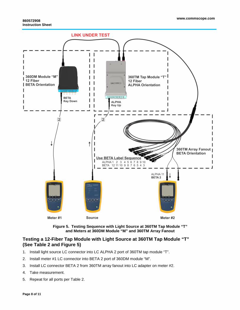
Figure 5. Testing Sequence with Light Source at 360TM Tap Module “T” and Meters at 360DM Module “M” and 360TM Array Fanout
Testing a 12-Fiber Tap Module with Light Source at 360TM Tap Module “T” (See Table 2 and Figure 5) 1. Install light source LC connector into LC ALPHA 2 port of 360TM tap module “T”.
2. Install meter #1 LC connector into BETA 2 port of 360DM module “M”.
3. Install LC connector BETA 2 from 360TM array fanout into LC adapter on meter #2.
4. Take measurement.
5. Repeat for all ports per Table 2.
Page 8 of 11
www.commscope.com 860572908 Instruction Sheet
Using the 24-Fiber Optical Tap Module Prior to testing, the source and meters should be referenced using an LC test jumper.
Table 3 provides the testing sequence when using a 24-fiber optical tap module with the light source at the 360DM module “M” and meters at the 360TM tap module “T” and 360TM array fanout. See Figure 6.
Table 3. Testing Sequence Using a 24-Fiber Optical Tap Module with Light Source at 360DM Module “M”
Source LC Position at Module “M”
Meter #1 LC Position at Module “T”
Meter #2 TAP Port 360TM
Array Fanout M-1 T-2 BETA 1 M-3 T-4 BETA 3 M-5 T-6 BETA 5 M-7 T-8 BETA 7 M-9 T-10 BETA 9 M-11 T-12 BETA 11
M-14 T-13 BETA 1 M-16 T-15 BETA 3 M-18 T-17 BETA 5 M-20 T-19 BETA 7 M-22 T-21 BETA 9 M-24 T-23 BETA 11
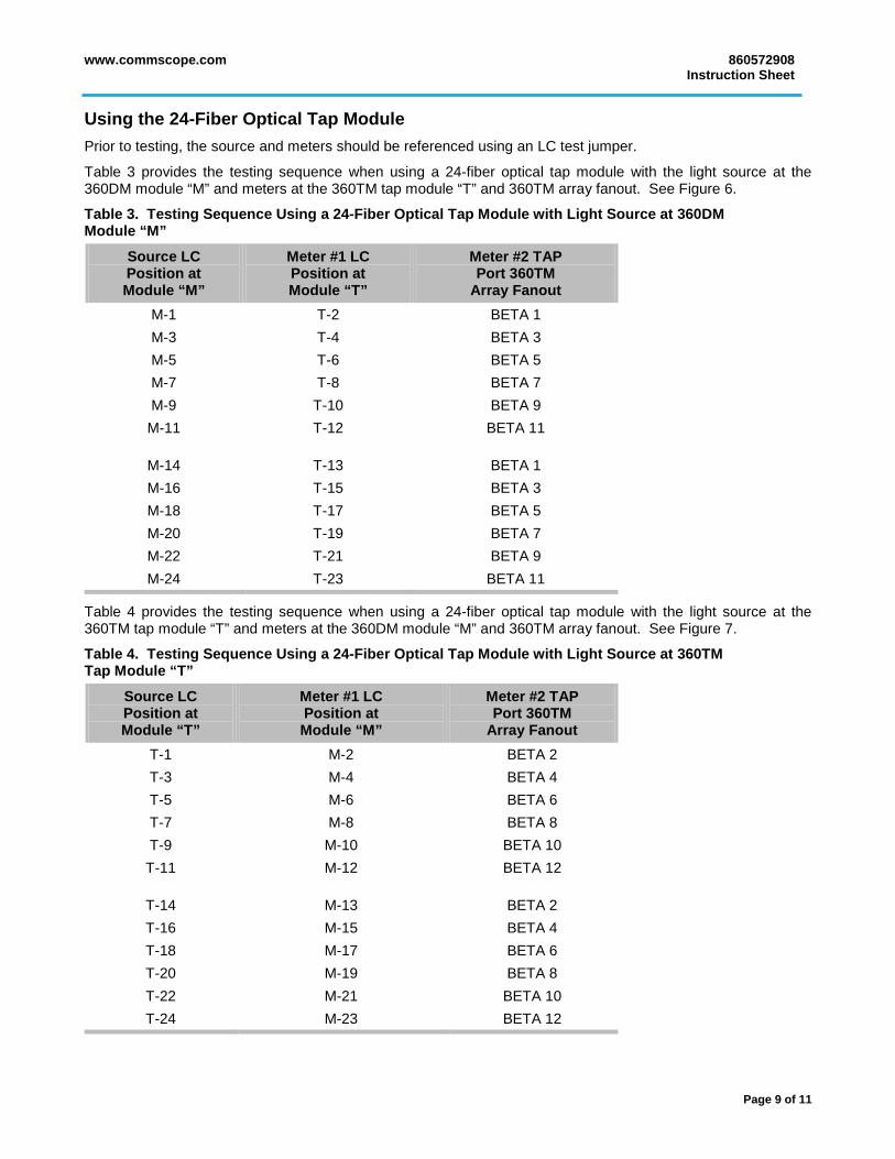
Table 4 provides the testing sequence when using a 24-fiber optical tap module with the light source at the 360TM tap module “T” and meters at the 360DM module “M” and 360TM array fanout. See Figure 7.
Table 4. Testing Sequence Using a 24-Fiber Optical Tap Module with Light Source at 360TM Tap Module “T”
Source LC Position at Module “T”
Meter #1 LC Position at Module “M”
Meter #2 TAP Port 360TM
Array Fanout T-1 M-2 BETA 2 T-3 M-4 BETA 4 T-5 M-6 BETA 6 T-7 M-8 BETA 8 T-9 M-10 BETA 10 T-11 M-12 BETA 12
T-14 M-13 BETA 2 T-16 M-15 BETA 4 T-18 M-17 BETA 6 T-20 M-19 BETA 8 T-22 M-21 BETA 10 T-24 M-23 BETA 12
Page 9 of 11

860572908 Instruction Sheet
www.commscope.com
Figure 6. Testing Sequence with Light Source at 360DM Module “M” and Meters at 360TM Tap Module “T” and 360TM Array Fanout
Testing a 24-Fiber Tap Module with Light Source at 360DM Module “M” (See Table 3 and Figure 6) 1. Install light source LC connector into BETA 1 port of 360DM module “M”.
2. Install meter #1 LC connector into ALPHA 2 port of 360TM tap module “T”.
3. Install LC connector BETA 1 from 360TM array fanout into LC adapter on meter #2.
4. Take measurement.
5. Repeat for all ports per Table 3.
Page 10 of 11

www.commscope.com 860572908 Instruction Sheet
Figure 7. Testing Sequence with Light Source at 360TM Tap Module “T” and Meters at 360DM Module “M” and 360TM Array Fanout
Testing a 24-Fiber Tap Module with Light Source at 360TM Tap Module “T” (See Table 4 and Figure 7) 1. Install light source LC connector into LC ALPHA 1 port of 360TM tap module “T”.
2. Install meter #1 LC connector into BETA 2 port of 360DM module “M”.
3. Install LC connector BETA 2 from 360TM array fanout into LC adapter on meter #2.
4. Take measurement.
5. Repeat for all ports per Table 4.
Page 11 of 11