instantaneous response of wide area intrusion sensor with long haul monitoring capability
TRANSCRIPT
IEEE PHOTONICS TECHNOLOGY LETTERS, VOL. 25, NO. 23, DECEMBER 1, 2013 2255
Instantaneous Response of Wide Area IntrusionSensor With Long Haul Monitoring Capability
Chang Hong Pua, Wu Yi Chong, and Harith Ahmad
Abstract— Current optical based wide area intrusion sensorsare very limited due to either a complicated setup, expensivefacilities, or long data acquisition time. Taking advantage ofacoustic wave on the laser dynamics behavior of erbium-dopedfiber laser (EDFL), an intrusion sensor with sensing length up to25 km was demonstrated in this letter. Different from an opticaltime domain reflectometer (OTDR) based vibration sensor thatneeds long data acquisition time to obtain average value frommultiple scans, this setup provided instantaneous response to themonitoring system as soon as the surrounding area of the sensoris triggered by vibration activities. As the dynamic behavior isdirectly detected as a large optical intensity fluctuation, henceconventional photo-detector and digital oscilloscope are the onlyfacilities needed in the monitoring system, which make the setupvery simple and cost effective.
Index Terms— Acoustic sensors, acousto-optic effects, erbiumdoped fiber lasers, intrusion sensor, laser dynamics.
I. INTRODUCTION
SENSOR and surveillance technologies today allow lawenforcement officer to monitor a location remotely from
distance. Current monitoring technologies include video cam-eras and television systems, audio receivers and recorders,motion and vibration detectors, heartbeat detectors, and nightvision and thermal imaging devices that detect infrared radi-ation or heat. Among these technologies, video, audio, andmotion sensing are among the most commonly used surveil-lance technologies. Motion sensing can be accomplished inseveral ways; two of the common ways are optical motionsensors such as optical passive infrared (PIR) devices andvibration sensors. For optical motion sensors, it is generallyknown that a clear line of sight is necessary to detect objectmotion or movement within the sensing range. Hence, hidingan optical motion sensor becomes a critical challenge in opticalmotion sensing. While for vibration sensors, the installationnormally can be embedded underground, inside a wall, or eveninside the casing of the glass windows making it possible forconcealment from trespasser.
In recent years, optical vibration sensors have gain popu-larity in sensing intrusion due to its ability in multi-functional
Manuscript received August 24, 2013; revised September 11, 2013; acceptedOctober 1, 2013. Date of publication October 7, 2013; date of current versionOctober 29, 2013. This work was supported in part by the University ofMalaya for providing the HIR Grant (Terahertz, UM.C / HIR / MOHE /SC / 01) and in part by MOHE and RU002/2013.
The authors are with the Photonics Research Centre, University ofMalaya, Kuala Lumpur 50603, Malaysia (e-mail: [email protected];[email protected]; [email protected]).
Color versions of one or more of the figures in this letter are availableonline at http://ieeexplore.ieee.org.
Digital Object Identifier 10.1109/LPT.2013.2284608
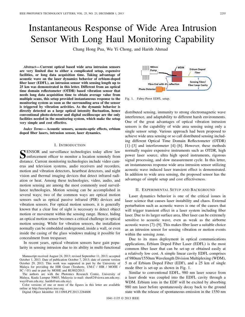
Fig. 1. Fabry-Perot EDFL setup.
distributed sensing, immunity to strong electromagnetic waveinterference, and adaptability to different harsh environments.One of the great advantages of optical vibration intrusionsensors is the capability of wide area sensing using only asingle sensor setup. Various approach had been proposed toachieve wide area sensing or so call distributed sensing includ-ing different Optical Time Domain Reflectometer (OTDR)[1]–[3] and interferometer [4]–[6]. However, these methodsnormally require expensive instruments such as OTDR, highpower laser source, ultra high speed instruments, rigoroussignal processing, and slow measurement cycle. In this letter,an instantaneous response wide area intrusion sensor utilizingacoustic wave induced laser transient effect is demonstrated.In addition to wide area sensing, the proposed sensor has theadvantage of simple setup and cost effectiveness.
II. EXPERIMENTAL SETUP AND BACKGROUND
Laser dynamics behavior is one of the critical issues inlaser science that causes laser instability and chaos. Externalperturbation such as acoustic waves is one of the causes thatwill trigger transient effect in a laser system including fiberlaser. Due to its larger surface area, fiber laser can be extremelysensitive to acoustic wave, even as weak as the airborneacoustic waves [7]–[9]. This makes fiber laser a suitable choiceas an intrusion sensor for sensing vibration or motion eventswithin the sensing zone.
Due to its mass deployment in optical communicationsapplications, Erbium Doped Fiber Laser (EDFL) is the mostcommon fiber laser that can be set-up or obtained easily ata relatively low cost. A simple linear cavity EDFL comprisesof 980nm/1550nm Wavelength Division Multiplexing (WDM),5 m of Erbium Doped Fiber (EDF), and a 25 km of singlemode fiber is set-up as shown in Fig. 1.
Similar to conventional EDFL, 980 nm laser source froma laser diode was coupled into the EDFL cavity through aWDM. Erbium ions in the EDF will be excited by absorbing980 nm laser before spontaneously decay back to the groundstate with the release of spontaneous emission in the 1550 nm
1041-1135 © 2013 IEEE

2256 IEEE PHOTONICS TECHNOLOGY LETTERS, VOL. 25, NO. 23, DECEMBER 1, 2013
Fig. 2. Simulation result of EDFL Turn-On Transient with parameters valueof k = 10 000, g = 90 000, and Ip = 130.
Conventional band (C-band). Some portion of the spontaneousemission will be guided by the fiber core and travel inboth directions along the fiber axis towards the fiber ends.At the fiber ends, ∼96% of the emission will travel outfrom the cavity while ∼4% will be reflected and feedbackto the laser cavity as a result of Fresnel’s reflection. Thesefeedback emissions will then be amplified through stimulatedemission by the excited Erbium ions. When the excitation rateis increased above the lasing threshold, laser action is formedin the laser cavity.
While most of the fiber laser sensors require an interrogatorto convert the phase shift, polarization state or wavelengthshift into intensity modulation of the laser cavity loss byexternal perturbation will directly cause the fluctuation of thelaser intensity in the case of laser dynamics behavior. Thelaser dynamics of EDFL can be derived from the basic rateequations using three level model [10], [11] to:
d I
dt= I (−k + gD), and (1)
d D
dt= − (1 + IP + 2I ) D + IP − 1
where I and IP in this case represent the laser and pumpintensity, D is the inverted population, k and g are the decayrate and unsaturated gain of the laser. These parameters arelink to the rate equations parameters as:
k ≡ γC
�21, g ≡ σS NT
�21, D ≡ N
NT,
IP≡ϕPσP
�21, I ≡ϕSσS
�21, and t ≡ T �21
where N is the population inversion (N2–N1), NT is the totalEr ions, γc represent the cavity decay rate, ϕp and ϕs is thenumber of pump and incident light photons, σp and σs is theabsorption and stimulated emission coefficient of pump andsignal, and �21 is the spontaneous transition probability of Erions from level 2 to level 1.
Simple numerical simulation using (1) and (2) was carriedout to study the optical intensity fluctuation of the EDFL underOn-Off condition by changing the pump intensity, Ip . Thesimulation result in Fig. 2 shows the optical output powerfluctuates at the onset of laser action by producing a seriesof spikes that decay exponentially before it comes to a stablestate. The dotted line is the laser output power level at stablestate. This phenomenon is named as Turn-On Transient [10].
Similar transient effect can be reproduced by changing thek parameter which represents the decay rate or the cavity loss
Fig. 3. Optical power fluctuation after an impact.
instead of Ip which is the pump power. k can be triggeredby inducing loss to the laser cavity through external force.Vibration is one of these external forces that can easily causethe fluctuation of value k by inducing losses in the fiber dueto the changes of refractive index. When a vibration sourceis placed near the EDFL, part of the vibration energy willbe transferred to the fiber and cause periodic refractive indexperturbation on the fiber due to stress optics effect [12]. Theserefractive index perturbation will induce temporary scatteringloss [13] to the fiber laser cavity causing the k value toincrease. When the EDFL is operating just above threshold,this sudden increase of k value will suppress the lasing effectand at the same time reduces the optical output power.
III. RESULTS AND DISCUSSION
Fig. 3 shows the fluctuation of the optical output powerwhen an impact is induced near the EDFL setup. As observed,the laser output power is under stable condition at the begin-ning. When an impact is induced, the optical power started tofluctuate and generates large power spikes. The spikes rapidlyincrease to a maximum and then decay exponentially to stablestate again which is similar to the simulation result. Inset ofFig. 3 enlarge the details of the optical power changes oncethe impact is induced. When the vibration energy is transferredto the EDFL, it causes scattering losses to the fiber laser.These losses will reduce the stimulated emission generationand suppress laser generation which leads to the drop of opticaloutput power as shown in the inset of Fig. 3. Meanwhile,population inversion is building up in the absence of stimulatedemission. This large population inversion will release at oncewhen the feedback of the laser is large enough to stimulatethe excited Er ions and generates large energy spikes.
Losses induced by the vibration energy from the vibrationis not constant as it is generated by the compression andrarefaction between molecules. At certain times when thelosses is low, spike will be generated. Once the vibrationenergy is transferred into the fiber, the loss induced is large andthe percentage of population inversion is low, hence the spikegenerated is low. When the population inversion builds upovertime, the spikes power also becomes larger until it reachesmaximum point (or the vibration energy is getting too weakinduced significant losses to the EDFL). At this point onwards,the EDFL is “free” from the disturbance of the vibration andtend to move into stable state by emitting multiple spikes withenergy decaying in exponential form which is the transienteffect.
Since, the k parameter represents the decay rate or cavityloss, the loss induced by the vibration to any part of the

PUA et al.: INSTANTANEOUS RESPONSE OF WIDE AREA INTRUSION SENSOR 2257
Fig. 4. Fluctuation amplitude of the laser output with refered to differentheight of the 100 g metal block drop.
laser cavity will trigger the dynamic behavior of the EDFL.Hence the whole EDFL is acting like a vibration sensorwith the total length of 25 km. This 25 km EDFL can bedistributed around a large area as an intrusion sensor. Forsensing application testing, 5 m of the SMF was unspooledand stuck on the floor tiles while other lengths remain in afiber spool. It is found that a soft contact on the fiber willinduce transient effect to the EDFL output. Transient effectis also induced by vibration occurs near the fiber. A test wascarried out to simulate the response of the EDFL output todifferent vibration energy by dropping a 100 g metal block ata distance of 10 cm away from the fiber from different height.
Fig. 4 shows the fluctuation amplitude of the optical outputpower at different incident vibration energy generated by thedrop of metal block at different height. The higher the drop,the larger the vibration energy. As observed, the fluctuationamplitude increase logarithmically with the incident vibrationenergy. Larger vibration energy will cause stronger scatteringin the fiber core leading to higher k value. At the same time, itis also observed that larger acoustic energy takes longer time todissipate, resulting in a longer recovery time for the EDFL toreturn to steady state. This leads to longer suppression of laseraction which in turn allows higher population inversion build-up. The result is that large number of photons is released in asingle shot, creating larger optical power fluctuation. However,this increase in fluctuation amplitude will slowly saturate asthe population inversion become higher and higher.
Although the intrusion sensor offers instantaneous responseto the surrounding vibration activities as most of the opticalvibration sensor do, it does not offer the location pinpointingcapability like OTDR (Optical Time Domain Reflectome-ter) [2]. A configuration of using two independent sensors withpart of their fiber length laid closely to each other to obtainpinpointing capability was tested as shown in Fig. 5(a). Whenan vibration is generated nearby these sensors, the vibrationwill reach one sensor before the other, causing a delay or timedifference between sensors. By setting up different separationsbetween the two sensors as shown in Fig. 5(a). The time delaybetween acoutic wave detection by the two sensors can thenbe used to estimate the position of the vibration activities.
Fig. 5(b) shows one of the measurement from both EDFL 1and EDFL 2 simultaneously using a digital oscilloscopewhen vibration is induced at 45 cm away from EDFL 1.3 observations were made: 1) two fluctuation packets wereobserved on EDFL 2 while only one was observed on EDFL 1;2) a time delay between both EDFL responses was observed;
Fig. 5. (a) Configuration for pinpoint location testing and (b) photodetectormeasurement from outputs EDFL 1 and EDFL 2 with separation 45 cm.
Fig. 6. Time delay for sensors separation at different distance.
and 3) Both EDFLs show different fluctuation amplitudes.The two fluctuation packets response in EDFL 2 is causedby the second impact of the metal block from bouncing onthe floor which is about 0.5s in this case. Each bounce createan impact which will then trigger the dynamic responses ofthe EDFLs. However, EDFL 1 shows only a single fluctuationpacket. As EDFL 1 is positioned closer to the impact point, itwill experience a larger vibration. EDFL 1 is still in transientcondition as a result of the strong vibration energy of the firstimpact during the arrival of the second impact and thus didnot register the latter. The vibration experienced by EDFL 2is smaller as can be seen by the fluctuation amplitude, whichenables EDFL 2 to return to the stable state before the arrivalof the second impact. Measurable delay can be observed onthe dynamic behaviur of EDFL 2 as compared to EDFL 1.Besides that, the optical output fluctuation of EDFL 2 isobviously smaller compared to EDFL 1 due to the loss ofvibration energy when it travels from EDFL 1 to EDFL 2.Fig. 6 shows the time delay between EDFL 1 and EDFL 2when the vibration is induced at different position along thefiber which have a different seperation distance.
From Fig. 6, the results do not seem to follow a linearrelationship. The time delay is expected to increase linearlywith the increase of separation distance, however it has sig-nificant discontinuity especially between separations of 30 cmto 40 cm. The large error and discontinuity might be causedby the efficiency of acoustic wave propagation from onepoint to the other and from tile to tile. When the sensoris placed on the ground, the ground condition will affectthe propagation speed and amplitude of the acoustic waveespecially from one medium to the other. However, the delayof the sensors responses still offers information from the fiberarrangement which is helpful in zone identification which willbe discussed in following section. Nevertheless, the proposedsensor provides a good foundation for the development ofintrusion sensor based on laser dynamic behavior in a fiberlaser.
2258 IEEE PHOTONICS TECHNOLOGY LETTERS, VOL. 25, NO. 23, DECEMBER 1, 2013
IV. PROPOSED APPLICATION SETUP
Previous section shows that there exist a few draws backfor practical deployment of the proposed intrusion sensor inreal life applications. The first is to differentiate two vibrationactivities that occur in a very short time interval and the secondis to identify the location of the vibration activities which iscritical in a sensing length of tens of kilometers.
To differentiate short interval vibration activities occurringalong the sensing length, multiple sensors can be embeddedat different depth into the ground to create condition similarto Fig. 5. For small vibration activities, sensor nearest to theground surface is triggered and will return to steady statewithin a short period of time before the onset of a secondevent. In the event of strong vibration activities, the triggereddynamic effect of this sensor will be large and its fluctuationwill overlap with a second vibration activity if it happens aftera short period of few milliseconds from the first event. In thiscase, the second layer of sensor which is embedded deeperunderground will work as the vibration activities identifier asthe vibration energy become weaker as it travels deeper intothe underground.
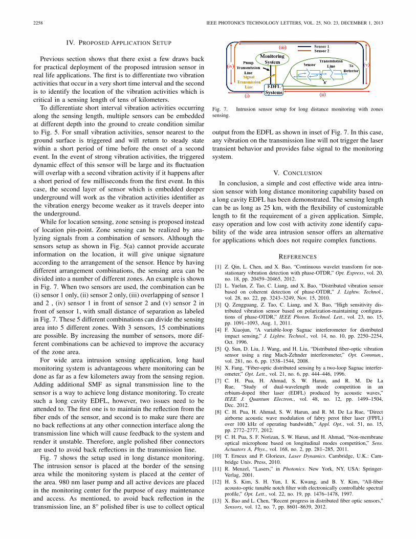
While for location sensing, zone sensing is proposed insteadof location pin-point. Zone sensing can be realized by ana-lyzing signals from a combination of sensors. Although thesensors setup as shown in Fig. 5(a) cannot provide accurateinformation on the location, it will give unique signatureaccording to the arrangement of the sensor. Hence by havingdifferent arrangement combinations, the sensing area can bedivided into a number of different zones. An example is shownin Fig. 7. When two sensors are used, the combination can be(i) sensor 1 only, (ii) sensor 2 only, (iii) overlapping of sensor 1and 2 , (iv) sensor 1 in front of sensor 2 and (v) sensor 2 infront of sensor 1, with small distance of separation as labeledin Fig. 7. These 5 different combinations can divide the sensingarea into 5 different zones. With 3 sensors, 15 combinationsare possible. By increasing the number of sensors, more dif-ferent combinations can be achieved to improve the accuracyof the zone area.
For wide area intrusion sensing application, long haulmonitoring system is advantageous where monitoring can bedone as far as a few kilometers away from the sensing region.Adding additional SMF as signal transmission line to thesensor is a way to achieve long distance monitoring. To createsuch a long cavity EDFL, however, two issues need to beattended to. The first one is to maintain the reflection from thefiber ends of the sensor, and second is to make sure there areno back reflections at any other connection interface along thetransmission line which will cause feedback to the system andrender it unstable. Therefore, angle polished fiber connectorsare used to avoid back reflections in the transmission line.
Fig. 7 shows the setup used in long distance monitoring.The intrusion sensor is placed at the border of the sensingarea while the monitoring system is placed at the center ofthe area. 980 nm laser pump and all active devices are placedin the monitoring center for the purpose of easy maintenanceand access. As mentioned, to avoid back reflection in thetransmission line, an 8° polished fiber is use to collect optical
Fig. 7. Intrusion sensor setup for long distance monitoring with zonessensing.
output from the EDFL as shown in inset of Fig. 7. In this case,any vibration on the transmission line will not trigger the lasertransient behavior and provides false signal to the monitoringsystem.
V. CONCLUSION
In conclusion, a simple and cost effective wide area intru-sion sensor with long distance monitoring capability based ona long cavity EDFL has been demonstrated. The sensing lengthcan be as long as 25 km, with the flexibility of customizablelength to fit the requirement of a given application. Simple,easy operation and low cost with activity zone identify capa-bility of the wide area intrusion sensor offers an alternativefor applications which does not require complex functions.
REFERENCES
[1] Z. Qin, L. Chen, and X. Bao, “Continuous wavelet transform for non-stationary vibration detection with phase-OTDR,” Opt. Express, vol. 20,no. 18, pp. 20459–20465, 2012.
[2] L. Yuelan, Z. Tao, C. Liang, and X. Bao, “Distributed vibration sensorbased on coherent detection of phase-OTDR,” J. Lightw. Technol.,vol. 28, no. 22, pp. 3243–3249, Nov. 15, 2010.
[3] Q. Zengguang, Z. Tao, C. Liang, and X. Bao, “High sensitivity dis-tributed vibration sensor based on polarization-maintaining configura-tions of phase-OTDR,” IEEE Photon. Technol. Lett., vol. 23, no. 15,pp. 1091–1093, Aug. 1, 2011.
[4] F. Xiaojun, “A variable-loop Sagnac interferometer for distributedimpact sensing,” J. Lightw. Technol., vol. 14, no. 10, pp. 2250–2254,Oct. 1996.
[5] Q. Sun, D. Liu, J. Wang, and H. Liu, “Distributed fiber-optic vibrationsensor using a ring Mach-Zehnder interferometer,” Opt. Commun.,vol. 281, no. 6, pp. 1538–1544, 2008.
[6] X. Fang, “Fiber-optic distributed sensing by a two-loop Sagnac interfer-ometer,” Opt. Lett., vol. 21, no. 6, pp. 444–446, 1996.
[7] C. H. Pua, H. Ahmad, S. W. Harun, and R. M. De LaRue, “Study of dual-wavelength mode competition in anerbium-doped fiber laser (EDFL) produced by acoustic waves,”IEEE J. Quantum Electron., vol. 48, no. 12, pp. 1499–1504,Dec. 2012.
[8] C. H. Pua, H. Ahmad, S. W. Harun, and R. M. De La Rue, “Directairborne acoustic wave modulation of fabry perot fiber laser (FPFL)over 100 kHz of operating bandwidth,” Appl. Opt., vol. 51, no. 15,pp. 2772–2777, 2012.
[9] C. H. Pua, S. F. Norizan, S. W. Harun, and H. Ahmad, “Non-membraneoptical microphone based on longitudinal modes competition,” Sens.Actuators A, Phys., vol. 168, no. 2, pp. 281–285, 2011.
[10] T. Erneux and P. Glorieux, Laser Dynamics. Cambridge, U.K.: Cam-bridge Univ. Press, 2010.
[11] R. Menzel, “Lasers,” in Photonics. New York, NY, USA: Springer-Verlag, 2001.
[12] H. S. Kim, S. H. Yun, I. K. Kwang, and B. Y. Kim, “All-fiberacousto-optic tunable notch filter with electronically controllable spectralprofile,” Opt. Lett., vol. 22, no. 19, pp. 1476–1478, 1997.
[13] X. Bao and L. Chen, “Recent progress in distributed fiber optic sensors,”Sensors, vol. 12, no. 7, pp. 8601–8639, 2012.