installing the txp mr 10e c and txp mr 10e l cards in the … · txp_mr_10e_c is tunable over the...
TRANSCRIPT
Installing the TXP_MR_10E_C and TXP_MR_10E_L Cards in the Cisco ONS 15454 SONET/SDH
Note The terms "Unidirectional Path Switched Ring" and "UPSR" may appear in Cisco literature. These terms do not refer to using Cisco ONS 15xxx products in a unidirectional path switched ring configuration. Rather, these terms, as well as "Path Protected Mesh Network" and "PPMN," refer generally to Cisco's path protection feature, which may be used in any topological network configuration. Cisco does not recommend using its path protection feature in any particular topological network configuration.
Product Names: 15454-10EMRC TXP, 15454-10EMRL TXP
This document provides a card description, specifications, and installation procedure for the MXP_MR_10E_C and MXP_MR_10E_L cards. These cards are compatible with the ONS 15454 SONET (ANSI) and the ONS 15454 SDH (ETSI) shelf assemblies. As appropriate, use this document in conjunction with the Cisco ONS 15454 DWDM Procedure Guide, the Cisco ONS 15454 DWDM Reference Manual, and the Cisco ONS 15454 DWDM Troubleshooting Guide.
This document contains the following sections:
• TXP_MR_10E_C and TXP_MR_10E_L Card Description, page 2
• TXP_MR_10E_C Card Specifications, page 8
• TXP_MR_10E_L Card Specifications, page 10
• Install the TXP_MR_10E_C and TXP_MR_10E_L Cards, page 12
• Related Documentation, page 14
• Obtaining Documentation and Submitting a Service Request, page 14
Corporate Headquarters:
© 2005-2007 Cisco Systems, Inc. All rights reserved.
Cisco Systems, Inc., 170 West Tasman Drive, San Jose, CA 95134-1706 USA
TXP_MR_10E_C and TXP_MR_10E_L Card Description
TXP_MR_10E_C and TXP_MR_10E_L Card DescriptionThe TXP_MR_10E_C and TXP_MR_10E_L cards are multirate transponders for the ONS 15454 platform. The cards are fully backward compatible with the TXP_MR_10G and TXP_MR_10E cards. They process one 10-Gbps signal (client side) into one 100-GHz DWDM signal (trunk side). The TXP_MR_10E_C is tunable over the entire set of C-band wavelength channels (82 channels spaced at 50 GHz on the ITU grid). The TXP_MR_10E_L is tunable over the entire set of L-band wavelength channels (80 channels spaced at 50 GHz on the ITU grid) and is well suited for use in networks that employ DS fiber or SMF-28 single-mode fiber. You can install TXP_MR_10E_C and TXP_MR_10E_L cards in Slots 1 to 6 and 12 to 17.
Key FeaturesThe key features of the TXP_MR_10E_C and TXP_MR_10E_L cards are:
• A tri-rate client interface (available through the ONS-XC-10G-S1 XFP, ordered separately):
– OC-192 (SR1)
– 10GE (10GBASE-LR)
– 10G-FC (1200-SM-LL-L)
• A UT2 module tunable through the entire C band (TXP_MR_10E_C card) or L band (TXP_MR_10E_L card). The channels are spaced at 50 GHz on the ITU grid.
• OC-192 to ITU-T G.709 OTU2 provisionable synchronous and asynchronous mapping.
• Client interfaces: The client interface is implemented with a separately orderable XFP module. The module is a tri-rate transceiver, providing a single port that can be configured in the field to support an OC-192 SR-1 (Telcordia GR-253-CORE) or STM-64 I-64.1 (ITU-T G.691) optical interfaces, as well as 10GE LAN PHY (10GBASE-LR), 10GE WAN PHY (10GBASE-LW), or 10G-FC signals. The XFP supports LC connectors and is equipped with a 1310-nm laser.
• Y-cable protection: This protection mechanism provides redundant bidirectional paths. Two cards can be joined in a Y-cable protection group with one card assigned as the working card and the other defined as the protection card. The Y-protection mechanism is provisionable and can be set ON or OFF (OFF is the default mode). When a signal fault is detected, the protection mechanism software automatically switches between paths.
• E-FEC capability: A key feature of the TXP_MR_10E_C and TXP_MR_10E_L cards is the availability to configure the forward error correction in three modes: NO FEC, FEC, and E-FEC. The output bit rate is always 10.7092 Gbps as defined in ITU-T G.709, but the error coding performance can be provisioned as follows:
– NO FEC—No forward error correction
– FEC—Standard ITU-T G.975 Reed-Solomon algorithm
– E-FEC—Standard ITU-T G.975.1 algorithm, which is a super FEC code
• Automatic laser shutdown: A safety mechanism used in the event of a fiber cut. The ALS procedure is supported on both client and trunk interfaces. On the client interface, ALS is compliant with ITU-T G.664 (6/99). On the data application and trunk interface, the switch on and off pulse duration is greater than 60 seconds. The on and off pulse duration is user-configurable.
• SONET/SDH Configurations: The cards can be provisioned in a linear configuration, BLSR/MS-SPRing, path protection/SNCP, or a regenerator. The cards can be used in the middle of BLSR/MS-SPRing or 1+1 spans when the cards are configured for transparent termination mode.
2Installing the TXP_MR_10E_C and TXP_MR_10E_L Cards in the Cisco ONS 15454 SONET/SDH
78-17338-01
TXP_MR_10E_C and TXP_MR_10E_L Card Description
Client and Trunk PortsThe TXP_MR_10E card features a universal transponder 2 (UT2) 1550-nm tunable laser (C band) or a UT2 1580-nm tunable laser (L band) for the trunk port and a separately orderable ONS-XC-10G-S1 1310-nm laser XFP module for the client port. On its faceplate, the TXP_MR_10E_C and TXP_MR_10E_L cards contain two transmit and receive connector pairs, one for the trunk port and one for the client port. Each connector pair is labeled.
DWDM Trunk InterfaceOn the trunk side, the TXP_MR_10E_C and TXP_MR_10E_L cards provide a 10-Gbps STM-64/OC-192 interface. There are 80 tunable channels available in the 1550-nm C band or 82 tunable channels available in the 1580-nm L band on the 50-GHz ITU grid for the DWDM interface. The TXP_MR_10E_C and TXP_MR_10E_C cards provide 3R transponder functionality for this 10-Gbps trunk interface. Therefore, the card is suited for use in long-range amplified systems. The DWDM interface is compliant with ITU-T G.707, ITU-T G.709, and Telcordia GR-253-CORE standards.
The DWDM trunk port operates at a rate that is dependent on the input signal and the presence or absence of the ITU-T G.709 Digital Wrapper/FEC. The possible trunk rates are:
• OC192 (9.95328 Gbps)
• OTU2 (10.70923 Gbps)
• 10GE (10.3125 Gbps) or 10GE into OTU2 (nonstandard 10.0957 Gbps)
• 10G-FC (10.51875 Gbps) or 10G-FC into OTU2 (nonstandard 11.31764 Gbps)
The maximum system reach in filterless applications without the use of optical amplification or regenerators is nominally rated at 23 dB over C-SMF fiber. This rating is not a product specification, but is given for informational purposes. It is subject to change.
Client-to-Trunk MappingThe TXP_MR_10E_C and TXP_MR_10E_L cards can perform ODU2-to-OCh mapping, which allows operators to provision data payloads in a standard way across 10-Gbps optical links.
Digital wrappers that define client side interfaces are called ODU2 entities in ITU-T G.709. Digital wrappers that define trunk side interfaces are called OCh in ITU-T G.709. ODU2 digital wrappers can include G-MPLS signaling extensions to ITU-T G.709 (such as LSP and G-PID values) to define client interfaces and payload protocols.
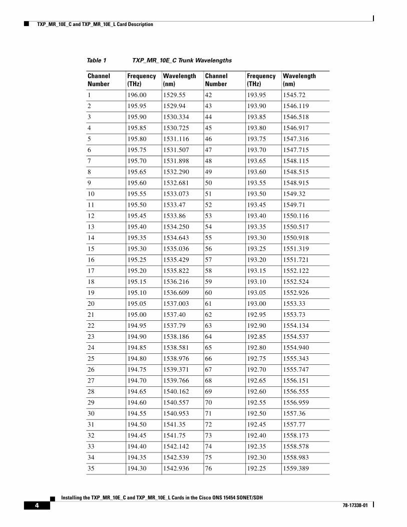
Wavelength IdentificationThe TXP_MR_10E_C card is tunable across 82 wavelengths in the C-band frequency plan, with channels on the ITU 50-GHz grid, as shown in Table 1.
3Installing the TXP_MR_10E_C and TXP_MR_10E_L Cards in the Cisco ONS 15454 SONET/SDH
78-17338-01
TXP_MR_10E_C and TXP_MR_10E_L Card Description
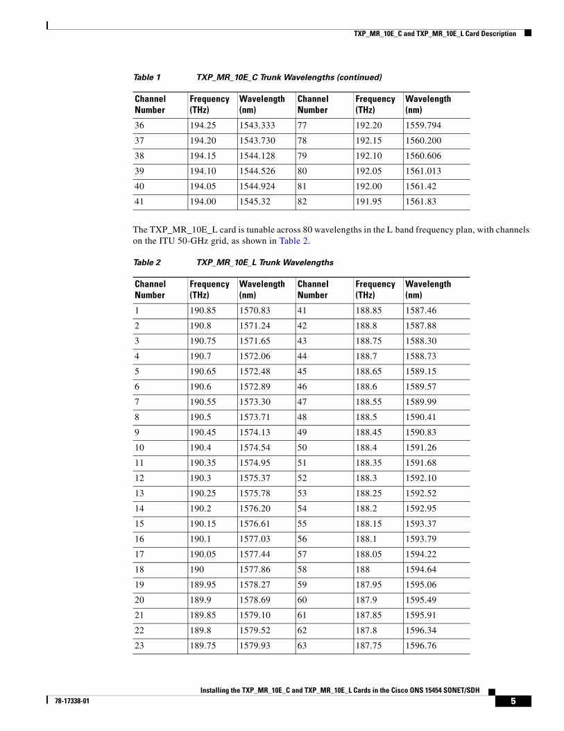
Table 1 TXP_MR_10E_C Trunk Wavelengths
Channel Number
Frequency (THz)
Wavelength (nm)
Channel Number
Frequency (THz)
Wavelength (nm)
1 196.00 1529.55 42 193.95 1545.72
2 195.95 1529.94 43 193.90 1546.119
3 195.90 1530.334 44 193.85 1546.518
4 195.85 1530.725 45 193.80 1546.917
5 195.80 1531.116 46 193.75 1547.316
6 195.75 1531.507 47 193.70 1547.715
7 195.70 1531.898 48 193.65 1548.115
8 195.65 1532.290 49 193.60 1548.515
9 195.60 1532.681 50 193.55 1548.915
10 195.55 1533.073 51 193.50 1549.32
11 195.50 1533.47 52 193.45 1549.71
12 195.45 1533.86 53 193.40 1550.116
13 195.40 1534.250 54 193.35 1550.517
14 195.35 1534.643 55 193.30 1550.918
15 195.30 1535.036 56 193.25 1551.319
16 195.25 1535.429 57 193.20 1551.721
17 195.20 1535.822 58 193.15 1552.122
18 195.15 1536.216 59 193.10 1552.524
19 195.10 1536.609 60 193.05 1552.926
20 195.05 1537.003 61 193.00 1553.33
21 195.00 1537.40 62 192.95 1553.73
22 194.95 1537.79 63 192.90 1554.134
23 194.90 1538.186 64 192.85 1554.537
24 194.85 1538.581 65 192.80 1554.940
25 194.80 1538.976 66 192.75 1555.343
26 194.75 1539.371 67 192.70 1555.747
27 194.70 1539.766 68 192.65 1556.151
28 194.65 1540.162 69 192.60 1556.555
29 194.60 1540.557 70 192.55 1556.959
30 194.55 1540.953 71 192.50 1557.36
31 194.50 1541.35 72 192.45 1557.77
32 194.45 1541.75 73 192.40 1558.173
33 194.40 1542.142 74 192.35 1558.578
34 194.35 1542.539 75 192.30 1558.983
35 194.30 1542.936 76 192.25 1559.389
4Installing the TXP_MR_10E_C and TXP_MR_10E_L Cards in the Cisco ONS 15454 SONET/SDH
78-17338-01
TXP_MR_10E_C and TXP_MR_10E_L Card Description
The TXP_MR_10E_L card is tunable across 80 wavelengths in the L band frequency plan, with channels on the ITU 50-GHz grid, as shown in Table 2.
36 194.25 1543.333 77 192.20 1559.794
37 194.20 1543.730 78 192.15 1560.200
38 194.15 1544.128 79 192.10 1560.606
39 194.10 1544.526 80 192.05 1561.013
40 194.05 1544.924 81 192.00 1561.42
41 194.00 1545.32 82 191.95 1561.83
Table 1 TXP_MR_10E_C Trunk Wavelengths (continued)
Channel Number
Frequency (THz)
Wavelength (nm)
Channel Number
Frequency (THz)
Wavelength (nm)
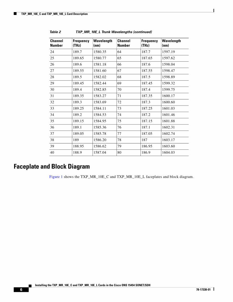
Table 2 TXP_MR_10E_L Trunk Wavelengths
Channel Number
Frequency (THz)
Wavelength (nm)
Channel Number
Frequency (THz)
Wavelength (nm)
1 190.85 1570.83 41 188.85 1587.46
2 190.8 1571.24 42 188.8 1587.88
3 190.75 1571.65 43 188.75 1588.30
4 190.7 1572.06 44 188.7 1588.73
5 190.65 1572.48 45 188.65 1589.15
6 190.6 1572.89 46 188.6 1589.57
7 190.55 1573.30 47 188.55 1589.99
8 190.5 1573.71 48 188.5 1590.41
9 190.45 1574.13 49 188.45 1590.83
10 190.4 1574.54 50 188.4 1591.26
11 190.35 1574.95 51 188.35 1591.68
12 190.3 1575.37 52 188.3 1592.10
13 190.25 1575.78 53 188.25 1592.52
14 190.2 1576.20 54 188.2 1592.95
15 190.15 1576.61 55 188.15 1593.37
16 190.1 1577.03 56 188.1 1593.79
17 190.05 1577.44 57 188.05 1594.22
18 190 1577.86 58 188 1594.64
19 189.95 1578.27 59 187.95 1595.06
20 189.9 1578.69 60 187.9 1595.49
21 189.85 1579.10 61 187.85 1595.91
22 189.8 1579.52 62 187.8 1596.34
23 189.75 1579.93 63 187.75 1596.76
5Installing the TXP_MR_10E_C and TXP_MR_10E_L Cards in the Cisco ONS 15454 SONET/SDH
78-17338-01
TXP_MR_10E_C and TXP_MR_10E_L Card Description
Faceplate and Block DiagramFigure 1 shows the TXP_MR_10E_C and TXP_MR_10E_L faceplates and block diagram.
24 189.7 1580.35 64 187.7 1597.19
25 189.65 1580.77 65 187.65 1597.62
26 189.6 1581.18 66 187.6 1598.04
27 189.55 1581.60 67 187.55 1598.47
28 189.5 1582.02 68 187.5 1598.89
29 189.45 1582.44 69 187.45 1599.32
30 189.4 1582.85 70 187.4 1599.75
31 189.35 1583.27 71 187.35 1600.17
32 189.3 1583.69 72 187.3 1600.60
33 189.25 1584.11 73 187.25 1601.03
34 189.2 1584.53 74 187.2 1601.46
35 189.15 1584.95 75 187.15 1601.88
36 189.1 1585.36 76 187.1 1602.31
37 189.05 1585.78 77 187.05 1602.74
38 189 1586.20 78 187 1603.17
39 188.95 1586.62 79 186.95 1603.60
40 188.9 1587.04 80 186.9 1604.03
Table 2 TXP_MR_10E_L Trunk Wavelengths (continued)
Channel Number
Frequency (THz)
Wavelength (nm)
Channel Number
Frequency (THz)
Wavelength (nm)
6Installing the TXP_MR_10E_C and TXP_MR_10E_L Cards in the Cisco ONS 15454 SONET/SDH
78-17338-01
TXP_MR_10E_C and TXP_MR_10E_L Card Description
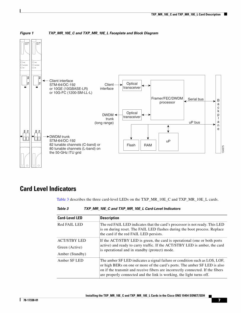
Figure 1 TXP_MR_10E_C and TXP_MR_10E_L Faceplate and Block Diagram
Card Level IndicatorsTable 3 describes the three card-level LEDs on the TXP_MR_10E_C and TXP_MR_10E_L cards.
uP bus
Serial bus
uPFlash RAM
Opticaltransceiver
1349
75
Framer/FEC/DWDMprocessor
Clientinterface
DWDMtrunk
(long range)
Opticaltransceiver
Client interfaceSTM-64/OC-192or 10GE (10GBASE-LR)or 10G-FC (1200-SM-LL-L)
Backplane
DWDM trunkSTM-64/OC-19282 tunable channels (C-band) or80 tunable channels (L-band) onthe 50-GHz ITU grid
FAIL
ACT/STBY
SF
10E MRTXP L
TX
RX
RX
TX
FAIL
ACT/STBY
SF
10E MRTXP C
TX
RX
RX
TX
Table 3 TXP_MR_10E_C and TXP_MR_10E_L Card-Level Indicators
Card-Level LED Description
Red FAIL LED The red FAIL LED indicates that the card’s processor is not ready. This LED is on during reset. The FAIL LED flashes during the boot process. Replace the card if the red FAIL LED persists.
ACT/STBY LED
Green (Active)
Amber (Standby)
If the ACT/STBY LED is green, the card is operational (one or both ports active) and ready to carry traffic. If the ACT/STBY LED is amber, the card is operational and in standby (protect) mode.
Amber SF LED The amber SF LED indicates a signal failure or condition such as LOS, LOF, or high BERs on one or more of the card’s ports. The amber SF LED is also on if the transmit and receive fibers are incorrectly connected. If the fibers are properly connected and the link is working, the light turns off.
7Installing the TXP_MR_10E_C and TXP_MR_10E_L Cards in the Cisco ONS 15454 SONET/SDH
78-17338-01

TXP_MR_10E_C Card Specifications
Port-Level IndicatorsTable 4 lists the four port-level LEDs on the TXP_MR_10E_C and TXP_MR_10E_L cards.
TXP_MR_10E_C Card SpecificationsThe TXP_MR_10E_C card has the following specifications:
• Line (trunk side)
– Bit rate: OC-192/STM-64 (9.95328 Gbps), OTU2 (10.70923 Gbps), 10GE (10.3125 Gbps), 10GE into OTU2 (non-standard 10.0957 Gbps), 10G FC (10.51875 Gbps), or 10G FC into OTU2 (non-standard 11.31764 Gbps)
– Code: Scrambled NRZ
– Fiber: 1550-nm single-mode
– Maximum chromatic dispersion allowance: +/– 1200 ps/nm (specified penalty)
– Loopback modes: Terminal and facility
Caution You must use a 15-dB fiber attenuator (10 to 20 dB) when working with the TXP_MR_10E_C card in a loopback on the trunk port. Do not use direct fiber loopbacks with the TXP_MR_10E_C card. Using direct fiber loopbacks causes irreparable damage to the TXP_MR_10E_C card.
– Connectors: LC
– Compliance: Telcordia GR-253-CORE, ITU-T G.707, ITU-T G.957, and ITU-T G.709
• Transmitter (trunk side)
– Maximum transmitter output power: +6 dBm
– Minimum transmitter output power: +3 dBm
– Transmitter: LN external modulator transmitter
– Wavelength stability (drift): +/– 25 picometers (pm)
Note An optical device on the card keeps the laser wavelength locked as closely as possible to the ITU nominal value. The allowed drift is +/– 25 pm.
• Receiver (trunk side)
Table 4 TXP_MR_10E_C and TXP_MR_10E_L Port-Level Indicators
Port-Level LED Description
Green Client LED The green Client LED indicates that the client port is in service and that it is receiving a recognized signal.
Green DWDM LED The green DWDM LED indicates that the DWDM port is in service and that it is receiving a recognized signal.
8Installing the TXP_MR_10E_C and TXP_MR_10E_L Cards in the Cisco ONS 15454 SONET/SDH
78-17338-01
TXP_MR_10E_C Card Specifications
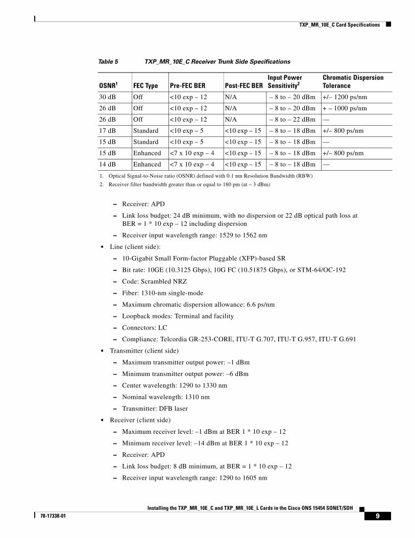
– Receiver: APD
– Link loss budget: 24 dB minimum, with no dispersion or 22 dB optical path loss at BER = 1 * 10 exp – 12 including dispersion
– Receiver input wavelength range: 1529 to 1562 nm
• Line (client side):
– 10-Gigabit Small Form-factor Pluggable (XFP)-based SR
– Bit rate: 10GE (10.3125 Gbps), 10G FC (10.51875 Gbps), or STM-64/OC-192
– Code: Scrambled NRZ
– Fiber: 1310-nm single-mode
– Maximum chromatic dispersion allowance: 6.6 ps/nm
– Loopback modes: Terminal and facility
– Connectors: LC
– Compliance: Telcordia GR-253-CORE, ITU-T G.707, ITU-T G.957, ITU-T G.691
• Transmitter (client side)
– Maximum transmitter output power: –1 dBm
– Minimum transmitter output power: –6 dBm
– Center wavelength: 1290 to 1330 nm
– Nominal wavelength: 1310 nm
– Transmitter: DFB laser
• Receiver (client side)
– Maximum receiver level: –1 dBm at BER 1 * 10 exp – 12
– Minimum receiver level: –14 dBm at BER 1 * 10 exp – 12
– Receiver: APD
– Link loss budget: 8 dB minimum, at BER = 1 * 10 exp – 12
– Receiver input wavelength range: 1290 to 1605 nm
Table 5 TXP_MR_10E_C Receiver Trunk Side Specifications
OSNR1
1. Optical Signal-to-Noise ratio (OSNR) defined with 0.1 nm Resolution Bandwidth (RBW)
FEC Type Pre-FEC BER Post-FEC BERInput Power Sensitivity2
2. Receiver filter bandwidth greater than or equal to 180 pm (at – 3 dBm)
Chromatic Dispersion Tolerance
30 dB Off <10 exp – 12 N/A – 8 to – 20 dBm +/– 1200 ps/nm
26 dB Off <10 exp – 12 N/A – 8 to – 20 dBm + – 1000 ps/nm
26 dB Off <10 exp – 12 N/A – 8 to – 22 dBm —
17 dB Standard <10 exp – 5 <10 exp – 15 – 8 to – 18 dBm +/– 800 ps/nm
15 dB Standard <10 exp – 5 <10 exp – 15 – 8 to – 18 dBm —
15 dB Enhanced <7 x 10 exp – 4 <10 exp – 15 – 8 to – 18 dBm +/– 800 ps/nm
14 dB Enhanced <7 x 10 exp – 4 <10 exp – 15 – 8 to – 18 dBm —
9Installing the TXP_MR_10E_C and TXP_MR_10E_L Cards in the Cisco ONS 15454 SONET/SDH
78-17338-01

TXP_MR_10E_L Card Specifications
• Environmental
– Operating temperature: –5 to +55 degrees Celsius (+23 to +113 degrees Fahrenheit)
– Operating humidity: 5 to 95 percent, noncondensing
– Power consumption: 50.00 W (maximum), 1.11 A at –48 V, 136.6 BTU/hr
• Dimensions
– Height: 12.650 in. (321.3 mm)
– Width: 0.716 in. (18.2 mm)
– Depth: 9.000 in. (228.6 mm)
– Depth with backplane connector: 9.250 in. (235 mm)
– Weight not including clam shell: 3.1 lb (1.3 kg)
TXP_MR_10E_L Card SpecificationsThe TXP_MR_10E_L card has the following specifications:
• Line (trunk side)
– Bit rate: OC-192/STM-64 (9.95328 Gbps), OTU2 (10.70923 Gbps), 10GE (10.3125 Gbps), 10GE into OTU2 (non-standard 10.0957 Gbps), 10G FC (10.51875 Gbps), or 10G FC into OTU2 (non-standard 11.31764 Gbps)
– Code: Scrambled NRZ
– Fiber: 1550-nm single-mode
– Maximum chromatic dispersion allowance: +/– 1200 ps/nm (specified penalty)
– Loopback modes: Terminal and facility
Caution You must use a 15-dB fiber attenuator (10 to 20 dB) when working with the TXP_MR_10E_L card in a loopback on the trunk port. Do not use direct fiber loopbacks with the TXP_MR_10E_L card. Using direct fiber loopbacks causes irreparable damage to the TXP_MR_10E_L card.
– Connectors: LC
– Compliance: Telcordia GR-253-CORE, ITU-T G.707, ITU-T G.957, and ITU-T G.709
• Transmitter (trunk side)
– Maximum transmitter output power: +6 dBm
– Minimum transmitter output power: +2 dBm
– Transmitter: LN external modulator transmitter
– Wavelength stability (drift): +/– 25 picometers (pm)
Note An optical device on the card keeps the laser wavelength locked as closely as possible to the ITU nominal value. The allowed drift is +/– 25 pm.
• Receiver (trunk side)
10Installing the TXP_MR_10E_C and TXP_MR_10E_L Cards in the Cisco ONS 15454 SONET/SDH
78-17338-01

TXP_MR_10E_L Card Specifications
– Receiver: APD
– Link loss budget: 24 dB minimum, with no dispersion or 22 dB optical path loss at BER = 1 * 10 exp – 12 including dispersion
– Receiver input wavelength range: 1570 to 1604 nm
• Line (client side):
– 10-Gigabit Small Form-factor Pluggable (XFP)-based SR
– Bit rate: 10GE (10.3125 Gbps), 10G FC (10.51875 Gbps), or STM-64/OC-192
– Code: Scrambled NRZ
– Fiber: 1310-nm single-mode
– Maximum chromatic dispersion allowance: 6.6 ps/nm
– Loopback modes: Terminal and facility
– Connectors: LC
– Compliance: Telcordia GR-253-CORE, ITU-T G.707, ITU-T G.957, ITU-T G.691
• Transmitter (client side)
– Maximum transmitter output power: –1 dBm
– Minimum transmitter output power: –6 dBm
– Center wavelength: 1290 to 1330 nm
– Nominal wavelength: 1310 nm
– Transmitter: DFB laser
• Receiver (client side)
– Maximum receiver level: –1 dBm at BER 1 * 10 exp – 12
– Minimum receiver level: –14 dBm at BER 1 * 10 exp – 12
– Receiver: APD
– Link loss budget: 8 dB minimum, at BER = 1 * 10 exp – 12
– Receiver input wavelength range: 1290 to 1605 nm
Table 6 TXP_MR_10E_L Receiver Trunk Side Specifications
OSNR1
1. Optical Signal-to-Noise ratio (OSNR) defined with 0.1 nm Resolution Bandwidth (RBW)
FEC Type Pre-FEC BER Post-FEC BERInput Power Sensitivity2
2. Receiver filter bandwidth greater than or equal to 180 pm (at – 3 dBm)
Chromatic Dispersion Tolerance
30 dB Off <10 exp – 12 N/A – 8 to – 20 dBm +/– 1200 ps/nm
26 dB Off <10 exp – 12 N/A – 8 to – 20 dBm + – 1000 ps/nm
26 dB Off <10 exp – 12 N/A – 8 to – 22 dBm —
17 dB Standard <10 exp – 5 <10 exp – 15 – 8 to – 18 dBm +/– 800 ps/nm
15 dB Standard <10 exp – 5 <10 exp – 15 – 8 to – 18 dBm —
15 dB Enhanced <7 x 10 exp – 4 <10 exp – 15 – 8 to – 18 dBm +/– 800 ps/nm
14 dB Enhanced <7 x 10 exp – 4 <10 exp – 15 – 8 to – 18 dBm —
11Installing the TXP_MR_10E_C and TXP_MR_10E_L Cards in the Cisco ONS 15454 SONET/SDH
78-17338-01
Install the TXP_MR_10E_C and TXP_MR_10E_L Cards
• Environmental
– Operating temperature: –5 to +55 degrees Celsius (+23 to +113 degrees Fahrenheit)
– Operating humidity: 5 to 95 percent, noncondensing
– Power consumption: 50.00 W (maximum), 1.11 A at –48 V, 136.6 BTU/hr
• Dimensions
– Height: 12.650 in. (321.3 mm)
– Width: 0.716 in. (18.2 mm)
– Depth: 9.000 in. (228.6 mm)
– Depth with backplane connector: 9.250 in. (235 mm)
– Weight not including clam shell: 3.1 lb (1.3 kg)
Install the TXP_MR_10E_C and TXP_MR_10E_L Cards
Warning During this procedure, wear grounding wrist straps to avoid ESD damage to the card. Do not directly touch the backplane with your hand or any metal tool, or you could shock yourself. Statement 94
Warning Class I (CDRH) and Class 1M (IEC) laser products. Statement 1055
Warning Invisible laser radiation may be emitted from disconnected fibers or connectors. Do not stare into beams or view directly with optical instruments. Statement 272
Note If protective clips are installed on the rear connectors of the cards, remove the clips before installing the cards.
Note If you install a card incorrectly, the FAIL LED flashes continuously.
Figure 2 shows general card installation.
12Installing the TXP_MR_10E_C and TXP_MR_10E_L Cards in the Cisco ONS 15454 SONET/SDH
78-17338-01
Install the TXP_MR_10E_C and TXP_MR_10E_L Cards
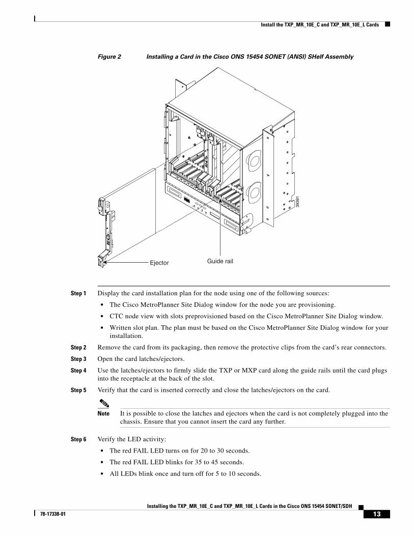
Figure 2 Installing a Card in the Cisco ONS 15454 SONET (ANSI) SHelf Assembly
Step 1 Display the card installation plan for the node using one of the following sources:
• The Cisco MetroPlanner Site Dialog window for the node you are provisioning.
• CTC node view with slots preprovisioned based on the Cisco MetroPlanner Site Dialog window.
• Written slot plan. The plan must be based on the Cisco MetroPlanner Site Dialog window for your installation.
Step 2 Remove the card from its packaging, then remove the protective clips from the card’s rear connectors.
Step 3 Open the card latches/ejectors.
Step 4 Use the latches/ejectors to firmly slide the TXP or MXP card along the guide rails until the card plugs into the receptacle at the back of the slot.
Step 5 Verify that the card is inserted correctly and close the latches/ejectors on the card.
Note It is possible to close the latches and ejectors when the card is not completely plugged into the chassis. Ensure that you cannot insert the card any further.
Step 6 Verify the LED activity:
• The red FAIL LED turns on for 20 to 30 seconds.
• The red FAIL LED blinks for 35 to 45 seconds.
• All LEDs blink once and turn off for 5 to 10 seconds.
FAN FAILCRIT
MAJMIN
3939
1
Guide railEjector
13Installing the TXP_MR_10E_C and TXP_MR_10E_L Cards in the Cisco ONS 15454 SONET/SDH
78-17338-01
Related Documentation
• The ACT or ACT/STBY LED turns on. The SF LED can persist until all card ports connect to their far-end counterparts and a signal is present.
Step 7 If the card does not boot up properly, or the LED activity does not occur as described in Step 6, check the following:
• When a physical card type does not match the type of card provisioned for that slot in CTC, the card might not boot. If a card does not boot, open CTC and ensure that the slot is not provisioned for a different card type before assuming that the card is faulty.
• If the red FAIL LED does not turn on, check the power.
• If you insert a card into a slot provisioned for a different card, all LEDs turn off.
• If the red FAIL LED is on continuously or the LEDs behave erratically, the card is not installed properly. Remove the card and repeat Steps 3 to 6.
Stop. You have completed this procedure.
Related Documentation• Cisco ONS 15454 DWDM Reference Manual
• Cisco ONS 15454 DWDM Procedure Guide
• Cisco ONS 15454 DWDM Troubleshooting Guide
• Cisco MetroPlanner DWDM Operations Guide
Obtaining Documentation and Submitting a Service RequestFor information on obtaining documentation, submitting a service request, and gathering additional information, see the monthly What’s New in Cisco Product Documentation, which also lists all new and revised Cisco technical documentation, at:
http://www.cisco.com/en/US/docs/general/whatsnew/whatsnew.html
Subscribe to the What’s New in Cisco Product Documentation as an RSS feed and set content to be delivered directly to your desktop using a reader application. The RSS feeds are a free service. Cisco currently supports RSS Version 2.0.
This document is to be used in conjunction with the documents listed in the “Related Documentation” section
14Installing the TXP_MR_10E_C and TXP_MR_10E_L Cards in the Cisco ONS 15454 SONET/SDH
78-17338-01
Related Documentation
© 2005-2007 Cisco Systems, Inc. All rights reserved.
Printed in the USA on recycled paper containing 10% postconsumer waste.
CCVP, the Cisco logo, and Welcome to the Human Network are trademarks of Cisco Systems, Inc.; Changing the Way We Work, Live, Play, and Learn isa service mark of Cisco Systems, Inc.; and Access Registrar, Aironet, Catalyst, CCDA, CCDP, CCIE, CCIP, CCNA, CCNP, CCSP, Cisco, the CiscoCertified Internetwork Expert logo, Cisco IOS, Cisco Press, Cisco Systems, Cisco Systems Capital, the Cisco Systems logo, Cisco Unity,Enterprise/Solver, EtherChannel, EtherFast, EtherSwitch, Fast Step, Follow Me Browsing, FormShare, GigaDrive, HomeLink, Internet Quotient, IOS,iPhone, IP/TV, iQ Expertise, the iQ logo, iQ Net Readiness Scorecard, iQuick Study, LightStream, Linksys, MeetingPlace, MGX, Networkers,Networking Academy, Network Registrar, PIX, ProConnect, ScriptShare, SMARTnet, StackWise, The Fastest Way to Increase Your Internet Quotient,and TransPath are registered trademarks of Cisco Systems, Inc. and/or its affiliates in the United States and certain other countries.
All other trademarks mentioned in this document or Website are the property of their respective owners. The use of the word partner does not imply apartnership relationship between Cisco and any other company. (0711R)
15Installing the TXP_MR_10E_C and TXP_MR_10E_L Cards in the Cisco ONS 15454 SONET/SDH
78-17338-01
Related Documentation
16Installing the TXP_MR_10E_C and TXP_MR_10E_L Cards in the Cisco ONS 15454 SONET/SDH
78-17338-01