installing the cisco ncs 2000 series passive optical modules ·...
TRANSCRIPT

Installing the Cisco NCS 2000 Series PassiveOptical Modules
Last Modified: 2019-02-22
Installing the Cisco NCS 2000 Series Passive Optical Modules
IntroductionThis document explains how to install and operate the Cisco NCS 2000 Series passive optical modules, thefiber shuffle, and the MPO fan-out unit. The Cisco NCS 2000 Series encompasses platforms from Cisco NCS2002 onwards.
The passive optical modules are used to build the optical network system. The fiber shuffle and MPO fan-outunit mechanically holds 14 and 10 passive optical modules respectively, thus enabling interconnection of flexspectrum ROADM nodes that contain 16-WXC or SMR-FS cards.
The passive optical modules, fiber shuffle, and MPO fan-out unit can be installed on:
• 19-inch (482.6 mm) or 23-inch (584.2 mm) EIA standard racks• 19-inch (482.6 mm) IEC rack• 600 mm x 600 mm or 600 mm x 300 mm ETSI rack
The following table lists the PIDs of the fiber shuffle and MPO fan-out unit:
Table 1: PIDs of the Fiber Shuffle and MPO Fan-out Unit
DescriptionModule
The MF-6RU unit is referred to as the fiber shuffle.
A combination of 14 single-slot NCS2K-MF-DEG-5(NCS2K-MF-DEG-5-CV) and NCS2K-MF-UPG-4(NCS2K-MF-UPG-4-CV) passive optical modulescan be installed in this unit. It is also possible to installa combination of 14 single-slotNCS2K-MF-2MPO-ADP, NCS2K-MF-4x4-COFS,NCS2K-MF-MPO-8LC, and NCS2K-MF-6AD-CFSpassive optical modules.
NCS2K-MF-6RU= (MF-6RU)
Installing the Cisco NCS 2000 Series Passive Optical Modules1
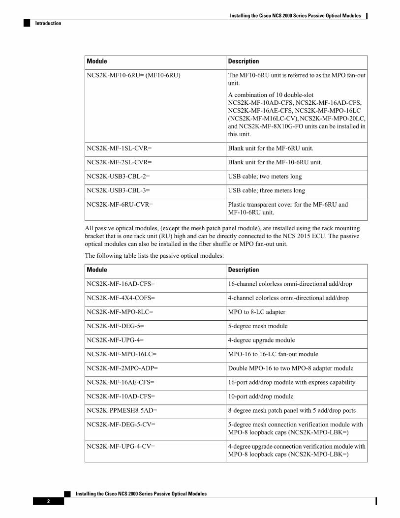
DescriptionModule
TheMF10-6RU unit is referred to as theMPO fan-outunit.
A combination of 10 double-slotNCS2K-MF-10AD-CFS, NCS2K-MF-16AD-CFS,NCS2K-MF-16AE-CFS, NCS2K-MF-MPO-16LC(NCS2K-MF-M16LC-CV),NCS2K-MF-MPO-20LC,and NCS2K-MF-8X10G-FO units can be installed inthis unit.
NCS2K-MF10-6RU= (MF10-6RU)
Blank unit for the MF-6RU unit.NCS2K-MF-1SL-CVR=
Blank unit for the MF-10-6RU unit.NCS2K-MF-2SL-CVR=
USB cable; two meters longNCS2K-USB3-CBL-2=
USB cable; three meters longNCS2K-USB3-CBL-3=
Plastic transparent cover for the MF-6RU andMF-10-6RU unit.
NCS2K-MF-6RU-CVR=
All passive optical modules, (except the mesh patch panel module), are installed using the rack mountingbracket that is one rack unit (RU) high and can be directly connected to the NCS 2015 ECU. The passiveoptical modules can also be installed in the fiber shuffle or MPO fan-out unit.
The following table lists the passive optical modules:
DescriptionModule
16-channel colorless omni-directional add/dropNCS2K-MF-16AD-CFS=
4-channel colorless omni-directional add/dropNCS2K-MF-4X4-COFS=
MPO to 8-LC adapterNCS2K-MF-MPO-8LC=
5-degree mesh moduleNCS2K-MF-DEG-5=
4-degree upgrade moduleNCS2K-MF-UPG-4=
MPO-16 to 16-LC fan-out moduleNCS2K-MF-MPO-16LC=
Double MPO-16 to two MPO-8 adapter moduleNCS2K-MF-2MPO-ADP=
16-port add/drop module with express capabilityNCS2K-MF-16AE-CFS=
10-port add/drop moduleNCS2K-MF-10AD-CFS=
8-degree mesh patch panel with 5 add/drop portsNCS2K-PPMESH8-5AD=
5-degree mesh connection verification module withMPO-8 loopback caps (NCS2K-MPO-LBK=)
NCS2K-MF-DEG-5-CV=
4-degree upgrade connection verificationmodule withMPO-8 loopback caps (NCS2K-MPO-LBK=)
NCS2K-MF-UPG-4-CV=
Installing the Cisco NCS 2000 Series Passive Optical Modules2
Installing the Cisco NCS 2000 Series Passive Optical ModulesIntroduction

DescriptionModule
MPO-16 to 16-LC fan-out connection verificationmodule with LC loopback caps (NCS2K-LC-LBK=)
NCS2K-MF-M16LC-CV=
MPO-24 to 20-LC fan-out moduleNCS2K-MF-MPO-20LC
Splitter/coupler module with six ports used ascolorless or gridless add/drop units in NCS2KROADM configurations.
NCS2K-MF-6AD-CFS=
MPO to LC fan-out module used as clientinterconnection for the NCS2K andNCS4K line cardsusing QSFP+ ports.
NCS2K-MF-8X10G-FO=
• All modules can be used to accommodate the ROADM nodes built with the SMR-FS and AD-FS cards.• A set of photodiodes are included on selected ports of each module for optical power monitoring.• USB communication channel can be used to retrieve the optical power levels monitored by the photodiodesand the inventory and insertion loss (IL) data of the optical paths stored in the modules. The USB channelcan also be used to activate electrical actuators or LEDs present on the front panel of the module.
• The xx SMR9 FS, SMR20 FS, or SMR20 FS CV and the 12-AD-FS or 16-AD-FS cards can beinterconnected by the NCS2K-MF-UPG-4=, NCS2K-MF-UPG-4-CV=, NCS2K-MF-DEG-5=,NCS2K-MF-DEG-5-CV=, NCS2K-MF-MPO-16LC=, NCS2K-MF-M16LC-CV=,NCS2K-MF-2MPO-ADP=, or the NCS2K-PPMESH8-5AD= module.
• The NCS2K-MF-16AE-CFS= and the NCS2K-MF-10AD-CFS= modules are only used as a passiveadd/drop modules in the Not-DWDM networks.
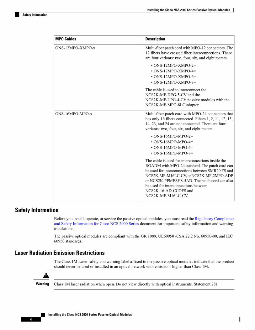
The following table lists the MPO cables that can be used with the passive modules from Release 10.6.1:
DescriptionMPO Cables
Fan-out cable with one MPO-24 connector on oneside and 16 LC connectors on the other side.
The cable is two meters long and can be used inROADM configurations with theNCS2K-MF-6AD-CFS module. This cable can alsobe used as a fan-out cable to connect the LC interfacedirectly to the SMR20 FS MPO ports.
ONS-MPO-16LC-2
Multi-fiber patch cord with MPO-12 connectors. The12 fibers have straight connections. There are fourvariants: two, four, six, and eight meters.
• ONS-12MPO-MPO-2=• ONS-12MPO-MPO-4=• ONS-12MPO-MPO-6=• ONS-12MPO-MPO-8=
The cables can interconnect the QSFP+ client portsof NCS2K-400G-2C2 and NCS4K-4H-OPW-QC2with the NCS2K-MF-8X10G-FO passive module.
ONS-12MPO-MPO-x
Installing the Cisco NCS 2000 Series Passive Optical Modules3
Installing the Cisco NCS 2000 Series Passive Optical ModulesIntroduction
DescriptionMPO Cables
Multi-fiber patch cord with MPO-12 connectors. The12 fibers have crossed fiber interconnections. Thereare four variants: two, four, six, and eight meters.
• ONS-12MPO-XMPO-2=• ONS-12MPO-XMPO-4=• ONS-12MPO-XMPO-6=• ONS-12MPO-XMPO-8=
The cable is used to interconnect theNCS2K-MF-DEG-5-CV and theNCS2K-MF-UPG-4-CV passive modules with theNCS2K-MF-MPO-8LC adapter.
ONS-12MPO-XMPO-x
Multi-fiber patch cord with MPO-24 connectors thathas only 16 fibers connected. Fibers 1, 2, 11, 12, 13,14, 23, and 24 are not connected. There are fourvariants: two, four, six, and eight meters.
• ONS-16MPO-MPO-2=• ONS-16MPO-MPO-4=• ONS-16MPO-MPO-6=• ONS-16MPO-MPO-8=
The cable is used for interconnections inside theROADMwith MPO-24 standard. The patch cord canbe used for interconnections between SMR20 FS andNCS2K-MF-M16LC-CV,orNCS2K-MF-2MPO-ADPor NCS2K-PPMESH8-5AD. The patch cord can alsobe used for interconnections betweenNCS2K-16-AD-CCOFS andNCS2K-MF-M16LC-CV.
ONS-16MPO-MPO-x
Safety InformationBefore you install, operate, or service the passive optical modules, you must read the Regulatory Complianceand Safety Information for Cisco NCS 2000 Series document for important safety information and warningtranslations.
The passive optical modules are compliant with the GR 1089, UL60950 /CSA 22.2 No. 60950-00, and IEC60950 standards.
Laser Radiation Emission RestrictionsThe Class 1M Laser safety and warning label affixed to the passive optical modules indicate that the productshould never be used or installed in an optical network with emissions higher than Class 1M.
Class 1M laser radiation when open. Do not view directly with optical instruments. Statement 281Warning
Installing the Cisco NCS 2000 Series Passive Optical Modules4
Installing the Cisco NCS 2000 Series Passive Optical ModulesSafety Information
Laser Safety During Operation
Invisible laser radiation may be emitted from disconnected fibers or connectors. Do not stare into beams orview directly with optical instruments. Statement 1051
Warning
Electrical SafetyThe passive optical modules are optically and electrically passive and require no electrical connections. Noelectrostatic discharge (ESD) or other electrical safety considerations apply.
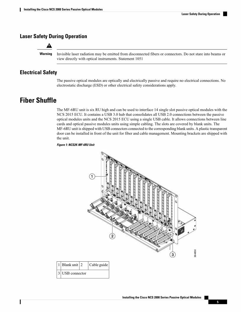
Fiber ShuffleThe MF-6RU unit is six RU high and can be used to interface 14 single slot passive optical modules with theNCS 2015 ECU. It contains a USB 3.0 hub that consolidates all USB 2.0 connections between the passiveoptical modules units and the NCS 2015 ECU using a single USB cable. It allows connections between linecards and optical passive modules units using simple cabling. The slots are covered by blank units. TheMF-6RU unit is shipped with USB connectors connected to the corresponding blank units. A plastic transparentdoor can be installed in front of the unit for fiber and cable management. Mounting brackets are shipped withthe unit.Figure 1: NCS2K-MF-6RU Unit
Cable guide2Blank unit1
USB connector3
Installing the Cisco NCS 2000 Series Passive Optical Modules5
Installing the Cisco NCS 2000 Series Passive Optical ModulesLaser Safety During Operation
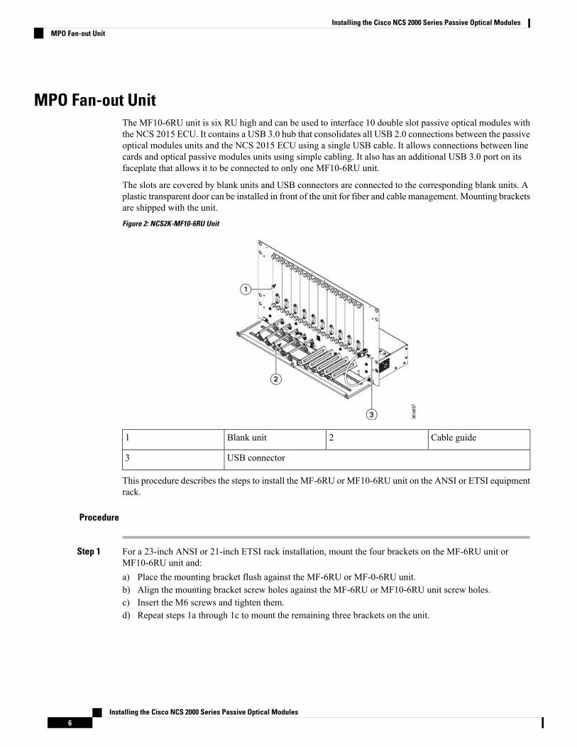
MPO Fan-out UnitThe MF10-6RU unit is six RU high and can be used to interface 10 double slot passive optical modules withthe NCS 2015 ECU. It contains a USB 3.0 hub that consolidates all USB 2.0 connections between the passiveoptical modules units and the NCS 2015 ECU using a single USB cable. It allows connections between linecards and optical passive modules units using simple cabling. It also has an additional USB 3.0 port on itsfaceplate that allows it to be connected to only one MF10-6RU unit.
The slots are covered by blank units and USB connectors are connected to the corresponding blank units. Aplastic transparent door can be installed in front of the unit for fiber and cable management. Mounting bracketsare shipped with the unit.Figure 2: NCS2K-MF10-6RU Unit
Cable guide2Blank unit1
USB connector3
This procedure describes the steps to install the MF-6RU or MF10-6RU unit on the ANSI or ETSI equipmentrack.
Procedure
Step 1 For a 23-inch ANSI or 21-inch ETSI rack installation, mount the four brackets on the MF-6RU unit orMF10-6RU unit and:a) Place the mounting bracket flush against the MF-6RU or MF-0-6RU unit.b) Align the mounting bracket screw holes against the MF-6RU or MF10-6RU unit screw holes.c) Insert the M6 screws and tighten them.d) Repeat steps 1a through 1c to mount the remaining three brackets on the unit.
Installing the Cisco NCS 2000 Series Passive Optical Modules6
Installing the Cisco NCS 2000 Series Passive Optical ModulesMPO Fan-out Unit
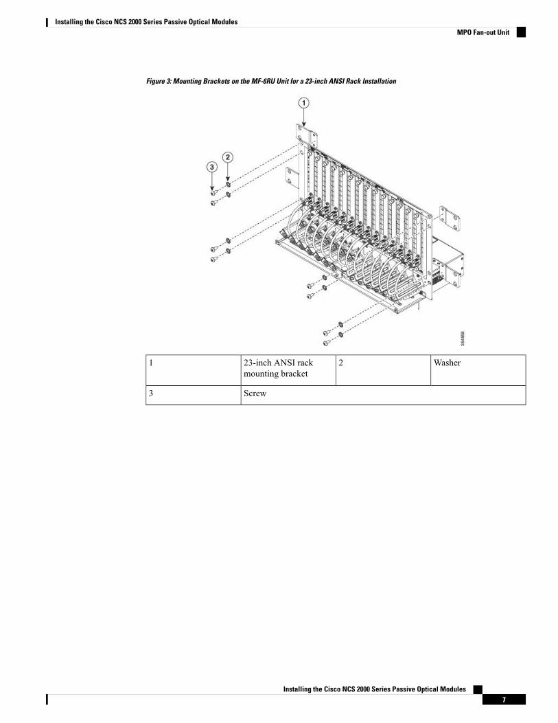
Figure 3: Mounting Brackets on the MF-6RU Unit for a 23-inch ANSI Rack Installation
Washer223-inch ANSI rackmounting bracket
1
Screw3
Installing the Cisco NCS 2000 Series Passive Optical Modules7
Installing the Cisco NCS 2000 Series Passive Optical ModulesMPO Fan-out Unit
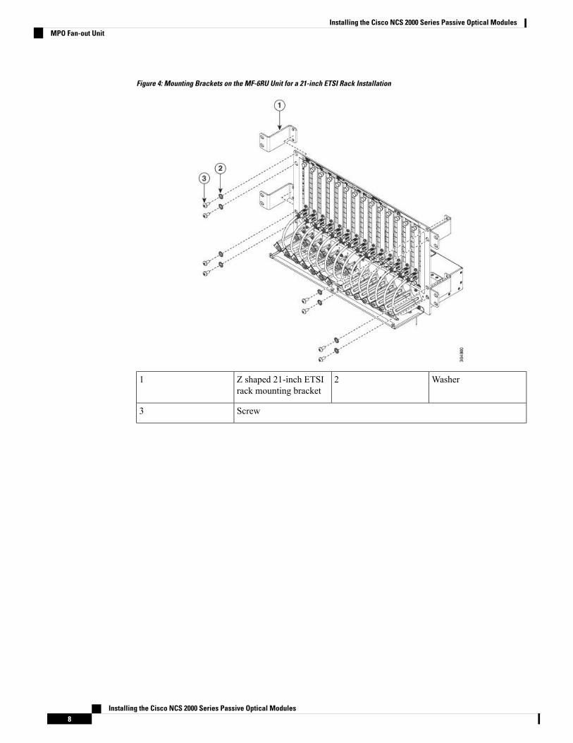
Figure 4: Mounting Brackets on the MF-6RU Unit for a 21-inch ETSI Rack Installation
Washer2Z shaped 21-inch ETSIrack mounting bracket
1
Screw3
Installing the Cisco NCS 2000 Series Passive Optical Modules8
Installing the Cisco NCS 2000 Series Passive Optical ModulesMPO Fan-out Unit

Figure 5: Mounting Brackets on the MF10-6RU Unit for a 23-inch ANSI Rack Installation
Washer223-inch ANSI rackmounting bracket
1
Screw3
Installing the Cisco NCS 2000 Series Passive Optical Modules9
Installing the Cisco NCS 2000 Series Passive Optical ModulesMPO Fan-out Unit
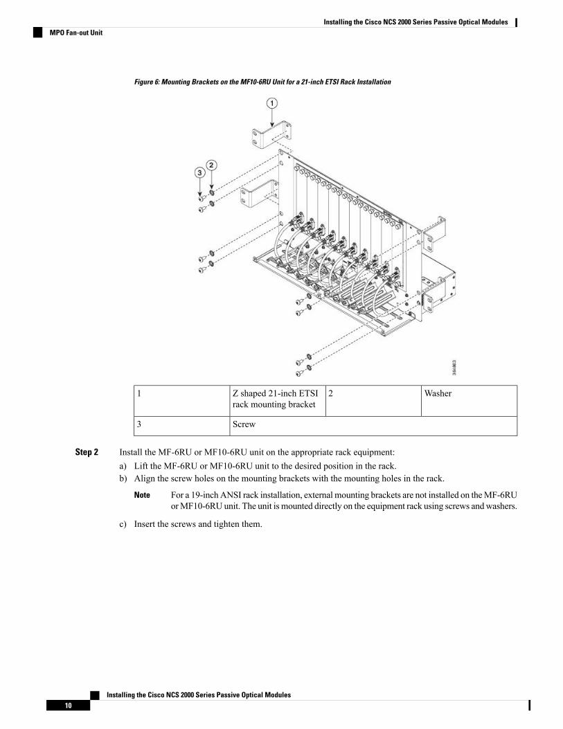
Figure 6: Mounting Brackets on the MF10-6RU Unit for a 21-inch ETSI Rack Installation
Washer2Z shaped 21-inch ETSIrack mounting bracket
1
Screw3
Step 2 Install the MF-6RU or MF10-6RU unit on the appropriate rack equipment:a) Lift the MF-6RU or MF10-6RU unit to the desired position in the rack.b) Align the screw holes on the mounting brackets with the mounting holes in the rack.
For a 19-inch ANSI rack installation, external mounting brackets are not installed on theMF-6RUorMF10-6RU unit. The unit is mounted directly on the equipment rack using screws andwashers.
Note
c) Insert the screws and tighten them.
Installing the Cisco NCS 2000 Series Passive Optical Modules10
Installing the Cisco NCS 2000 Series Passive Optical ModulesMPO Fan-out Unit

Figure 7: Mounting the MF-6RU Unit for a 19-inch ANSI Equipment Rack
Washer2Screw1
Figure 8: Mounting the MF10-6RU Unit for a 19-inch ANSI Equipment Rack
Washer2Screw1
Step 3 Establish grounding for the MF-6RU or MF10-6RU unit:
Installing the Cisco NCS 2000 Series Passive Optical Modules11
Installing the Cisco NCS 2000 Series Passive Optical ModulesMPO Fan-out Unit

a) Crimp a #6 AWG ground cable to the ground lug.b) Attach the ground lug to the MF-6RU or MF10-6RU unit The ground points are present on the rear side
of the unit as shown in the following figure.c) Tighten the lug using two M6 screws.d) Terminate the other end of the ground cable either at the office ground point or the rack ground point.
Grounding the MF-6RU or MF10-6RU Unit 365893.eps
Serrated washer2M6 x 10 screw1
Grounding point4Grounding lug3
Installing Transparent Door on MF-6RU or MF10-6RU UnitThis procedure describes the steps to install the transparent door on the MF-6RU or MF10-6RU unit.
Procedure
Step 1 Install the top cover on the MF-6RU or MF10-6RU unit using four M3 screws.Step 2 Before installing the door, adjust the cable guide tray so that the door screws are properly aligned.Step 3 Install the transparent door to the MF-6RU or MF10-6RU (Figure 10) unit using six self-clinching screws.
Figure 9: Installing the Transparent Door on the MF10-6RU Unit
Installing the Cisco NCS 2000 Series Passive Optical Modules12
Installing the Cisco NCS 2000 Series Passive Optical ModulesInstalling Transparent Door on MF-6RU or MF10-6RU Unit
Transparent Door2Top cover1
Rack Mounting BracketAll passive optical modules, except for the 8-degree mesh patch panel module, are installed using the rackmounting bracket (NCS2K-MF-1RU=). The rack mounting bracket is 19 inches (482.6-mm) wide and canbe mounted on a 19-inch (482.6-mm) ANSI or an IEC equipment rack. However, by using a pair of externalbrackets (either straight or Z-shaped), it can also be mounted on a 23-inch (584.2-mm) ANSI, a 600 x 600mm (23.6 x 23.6-inch), or a 600 x 300 mm (23.6 x 11.8-inch) equipment rack.
The Cisco NCS passive optical modules size can be single slot or double slot.
• Single slot cassette units: NCS2K-MF-4X4-COFS=, NCS2K-MF-MPO-8LC=, NCS2K-MF-DEG-5=,NCS2K-MF-DEG-5-CV=,NCS2K-MF-UPG-4=,NCS2K-MF-UPG-4-CV=,NCS2K-MF-2MPO-ADP=,NCS2K-MF-6AD-CFS=, blank-slot filler panel.
• Double slot cassette units: NCS2K-MF-16AD-CFS=, NCS2K-MF-MPO-16LC=,NCS2K-MF-M16LC-CV=,NCS2K-MF-16AE-CFS=,NCS2K-MF-10AD-CFS=,NCS2K-MF-MPO-20LC,NCS2K-MF-8X10G-FO=.
The rack mounting bracket has two cut outs.
• Each cut out (left or right) can accommodate two single slot cassettes, for a total of four single slotcassettes in the rack mounting bracket.
• Each cut out (left or right) can also accommodate one double slot cassette, for a total of two double slotcassettes in the rack mounting bracket.
• If a rack mounting bracket slot remains empty, it can be filled with a blank-slot filler panels.
Diagram 1 in the following figure indicates the rack mounting bracket installed on a 19-inch ANSI or IECequipment rack.
Diagram 2 in the following figure indicates the rack mounting bracket installed on a 23-inch ANSI equipmentrack.
Diagram 3 in the following figure indicates the rack mounting bracket installed on an ETSI equipment rack.
Installing the Cisco NCS 2000 Series Passive Optical Modules13
Installing the Cisco NCS 2000 Series Passive Optical ModulesRack Mounting Bracket

Figure 10: Rack Mounting Bracket
Front Panel LayoutThe following figure shows the front panel layout of the passive optical modules.
Installing the Cisco NCS 2000 Series Passive Optical Modules14
Installing the Cisco NCS 2000 Series Passive Optical ModulesFront Panel Layout

Figure 11: Front Panel Layout 1
The front panel layout for the 5-degree Mesh Connection Verification Module is the same as the 5-degreeMesh Module layout and the layout for the 4-degree Upgrade Connection Verification Module is the sameas the 4-degree Upgrade Module layout.
Note
Installing the Cisco NCS 2000 Series Passive Optical Modules15
Installing the Cisco NCS 2000 Series Passive Optical ModulesFront Panel Layout

Figure 12: Front Panel Layout 2
Installing the Cisco NCS 2000 Series Passive Optical Modules16
Installing the Cisco NCS 2000 Series Passive Optical ModulesFront Panel Layout

The MPO-8 and MPO-16 cables have a similar physical appearance. Hence, when connecting the cables tothe MPO-8 or MPO-16 adapters, use only MPO-8 and MPO-16 cables to connect to their respective adaptersbecause the optical signals will not pass through the module if a wrong cable is used.
Note
The front panel layout for the MPO-16 to 16-LC Fan-out Connection Verification Module is the same as theMPO-16 to 16-LC Fan-out Module layout.
Note
Figure 13: Front Panel Layout 3
Components of Cisco NCS 2000 Series Passive Optical ModulesThe components of Cisco NCS 2000 Series passive optical modules are:
16-channel Colorless Omni-directional Add/Drop (NCS2K-MF-16AD-CFS=)The following are the features of 16-channel colorless omni-directional add/drop passive module:
• Comprises one 1x16 splitter, one 16x1 combiner, and seventeen photodiodes arranged as shown in thefollowing figure.
• This is a double slot module in the Cisco NCS2K-MF-1RU chassis.• Embeds PDs for connectivity check and monitoring purposes.• Virtual PDs are implemented by the unit on the drop ports.• At CTC level, 33 power values are reported.• USB connection can provide power values at PD and the manufacturing data stored in the flash memory.
Installing the Cisco NCS 2000 Series Passive Optical Modules17
Installing the Cisco NCS 2000 Series Passive Optical ModulesComponents of Cisco NCS 2000 Series Passive Optical Modules

Figure 14: Optical layout of 16-channel colorless omni-directional add/drop
4-channel Colorless Omni-directional Add/Drop (NCS2K-MF-4X4-COFS=)The following are the features of 4-channel colorless omni-directional add/drop passive module:
• Passive unit comprising of eight 2x2 optical couplers and eight photodiodes, arranged as shown in thefollowing figure.
• This is a single slot module in the Cisco NCS2K-MF-1RU chassis.• Power monitoring is present at each channel input port and at each common input port.• Virtual PDs are implemented on the channel drop ports.• At CTC level, 12 power values are reported.
Installing the Cisco NCS 2000 Series Passive Optical Modules18
Installing the Cisco NCS 2000 Series Passive Optical Modules4-channel Colorless Omni-directional Add/Drop (NCS2K-MF-4X4-COFS=)

Figure 15: Optical layout of 4-channel colorless omni-directional add/drop
MPO to 8-LC Adapter (NCS2K-MF-MPO-8LC=)The following are the features of the MPO to 8-LC adapter:
• Fan-out of the MPO-APC connectors to/from eight LC-PC connections.• A total of eight photodiodes provide power monitoring of channel input and output port.• This is a single slot module in the Cisco NCS2K-MF-1RU chassis.
Installing the Cisco NCS 2000 Series Passive Optical Modules19
Installing the Cisco NCS 2000 Series Passive Optical ModulesMPO to 8-LC Adapter (NCS2K-MF-MPO-8LC=)
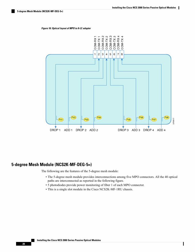
Figure 16: Optical layout of MPO to 8-LC adapter
5-degree Mesh Module (NCS2K-MF-DEG-5=)The following are the features of the 5-degree mesh module:
• The 5-degree mesh module provides interconnections among five MPO connectors. All the 40 opticalpaths are interconnected as reported in the following figure.
• 5 photodiodes provide power monitoring of fiber 1 of each MPO connector.• This is a single slot module in the Cisco NCS2K-MF-1RU chassis.
Installing the Cisco NCS 2000 Series Passive Optical Modules20
Installing the Cisco NCS 2000 Series Passive Optical Modules5-degree Mesh Module (NCS2K-MF-DEG-5=)

Figure 17: Optical layout of 5-degree mesh module
4-degree Upgrade Module (NCS2K-MF-UPG-4=)The following are the features of the 5-degree mesh module:
• The 4-degree upgrade module provides interconnections among 8 MPO.• 64 optical paths are interconnected as reported in the following figure.• Eight photodiodes provide power monitoring of fiber 1 of each MPO connector.• This is a single slot module in the Cisco NCS2K-MF-1RU chassis.
Installing the Cisco NCS 2000 Series Passive Optical Modules21
Installing the Cisco NCS 2000 Series Passive Optical Modules4-degree Upgrade Module (NCS2K-MF-UPG-4=)

Figure 18: Optical layout of 4-Degree upgrade module
MPO-16 to 16-LC Fan-out Module (NCS2K-MF-MPO-16LC=)TheMPO-16 to 16-LC fan-out module is a double slot module with one MPO-16 connector (COM) and eightLC duplex connectors (Port-i-TX/RX). It contains 16 photodiodes to monitor the power of the channel inputports.
The MPO-16 connector is compatible with the SMR20 FS EXP and 16-AD-FS CH ports.
The features of the MPO-16 to 16-LC fan-out module are:
• It provides fan-out of the MPO-16 connector to or from the LC connections.• It is used to interconnect the optical modules having LC connectors (TXP) with modules havingMPO-16connectors ( SMR20 FS / SMR20 FS CV and 16-AD-FS).
Installing the Cisco NCS 2000 Series Passive Optical Modules22
Installing the Cisco NCS 2000 Series Passive Optical ModulesMPO-16 to 16-LC Fan-out Module (NCS2K-MF-MPO-16LC=)

Figure 19: Optical layout of MPO-16 to 16-LC fan-out module
Double MPO-16 to Two MPO-8 Adapter Module (NCS2K-MF-2MPO-ADP=)The double MPO-16 to two MPO-8 adapter module is a single slot module with two MPO-16 connectors andfour MPO-8 connectors. It contains six embedded photodiodes for connectivity check and monitoring.
TheMPO-16 connectors are compatible with SMR20 FS EXP ports and theMPO-8 connectors are compatiblewith MF-DEG-5 or MF-UPG-4 patch panel modules.
The features of the double MPO-16 to two MPO-8 adapter module are:
• It provides interconnection between oneMPO-16 and twoMPO-8 connectors. Two instances ofMPO-16and MPO-8 connector combination is implemented on the module with one MPO-16 connector and twoMPO-8 connectors in each instance. This allows two interconnections.
• It is used to interconnect the optical modules having MPO-16 connectors (SMR20 FS / SMR20 FS CV)with modules having MPO-8 connectors (patch panel modules like NCS2K-MF-DEG-5= andNCS2K-MF-UPG-4=).
Installing the Cisco NCS 2000 Series Passive Optical Modules23
Installing the Cisco NCS 2000 Series Passive Optical ModulesDouble MPO-16 to Two MPO-8 Adapter Module (NCS2K-MF-2MPO-ADP=)
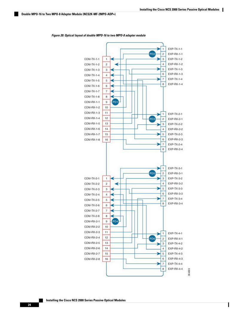
Figure 20: Optical layout of double MPO-16 to two MPO-8 adapter module
Installing the Cisco NCS 2000 Series Passive Optical Modules24
Installing the Cisco NCS 2000 Series Passive Optical ModulesDouble MPO-16 to Two MPO-8 Adapter Module (NCS2K-MF-2MPO-ADP=)
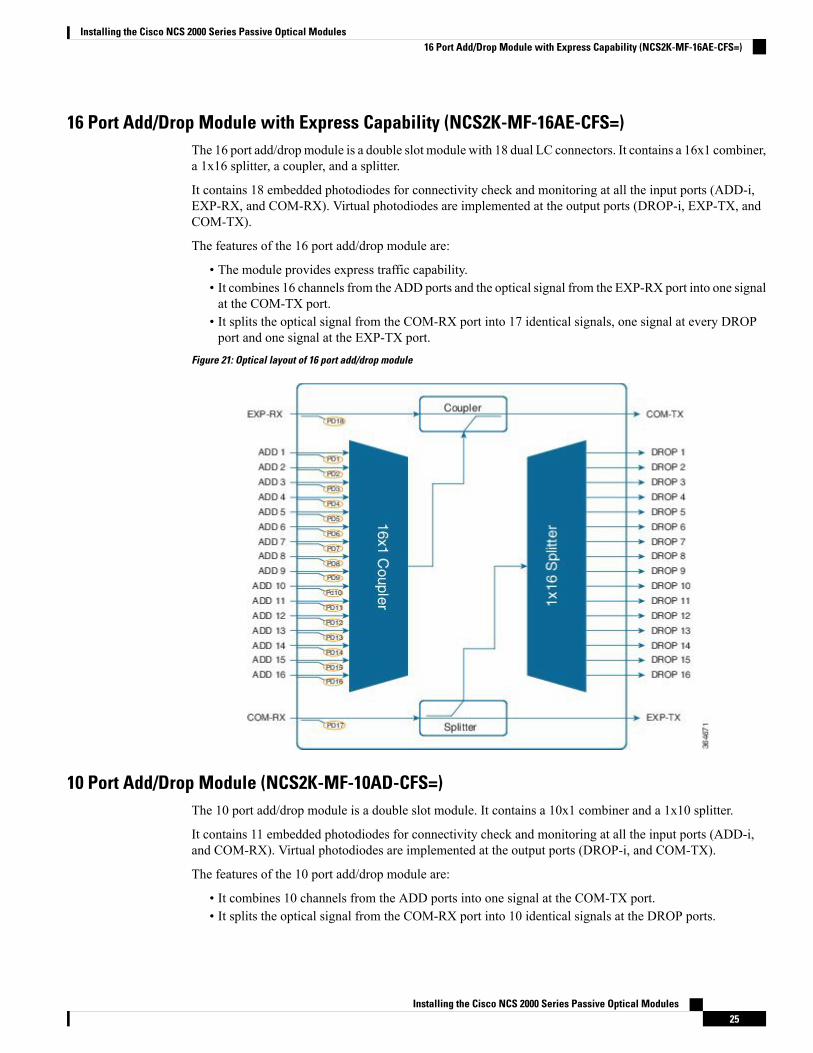
16 Port Add/Drop Module with Express Capability (NCS2K-MF-16AE-CFS=)The 16 port add/dropmodule is a double slot module with 18 dual LC connectors. It contains a 16x1 combiner,a 1x16 splitter, a coupler, and a splitter.
It contains 18 embedded photodiodes for connectivity check and monitoring at all the input ports (ADD-i,EXP-RX, and COM-RX). Virtual photodiodes are implemented at the output ports (DROP-i, EXP-TX, andCOM-TX).
The features of the 16 port add/drop module are:
• The module provides express traffic capability.• It combines 16 channels from the ADD ports and the optical signal from the EXP-RX port into one signalat the COM-TX port.
• It splits the optical signal from the COM-RX port into 17 identical signals, one signal at every DROPport and one signal at the EXP-TX port.
Figure 21: Optical layout of 16 port add/drop module
10 Port Add/Drop Module (NCS2K-MF-10AD-CFS=)The 10 port add/drop module is a double slot module. It contains a 10x1 combiner and a 1x10 splitter.
It contains 11 embedded photodiodes for connectivity check and monitoring at all the input ports (ADD-i,and COM-RX). Virtual photodiodes are implemented at the output ports (DROP-i, and COM-TX).
The features of the 10 port add/drop module are:
• It combines 10 channels from the ADD ports into one signal at the COM-TX port.• It splits the optical signal from the COM-RX port into 10 identical signals at the DROP ports.
Installing the Cisco NCS 2000 Series Passive Optical Modules25
Installing the Cisco NCS 2000 Series Passive Optical Modules16 Port Add/Drop Module with Express Capability (NCS2K-MF-16AE-CFS=)
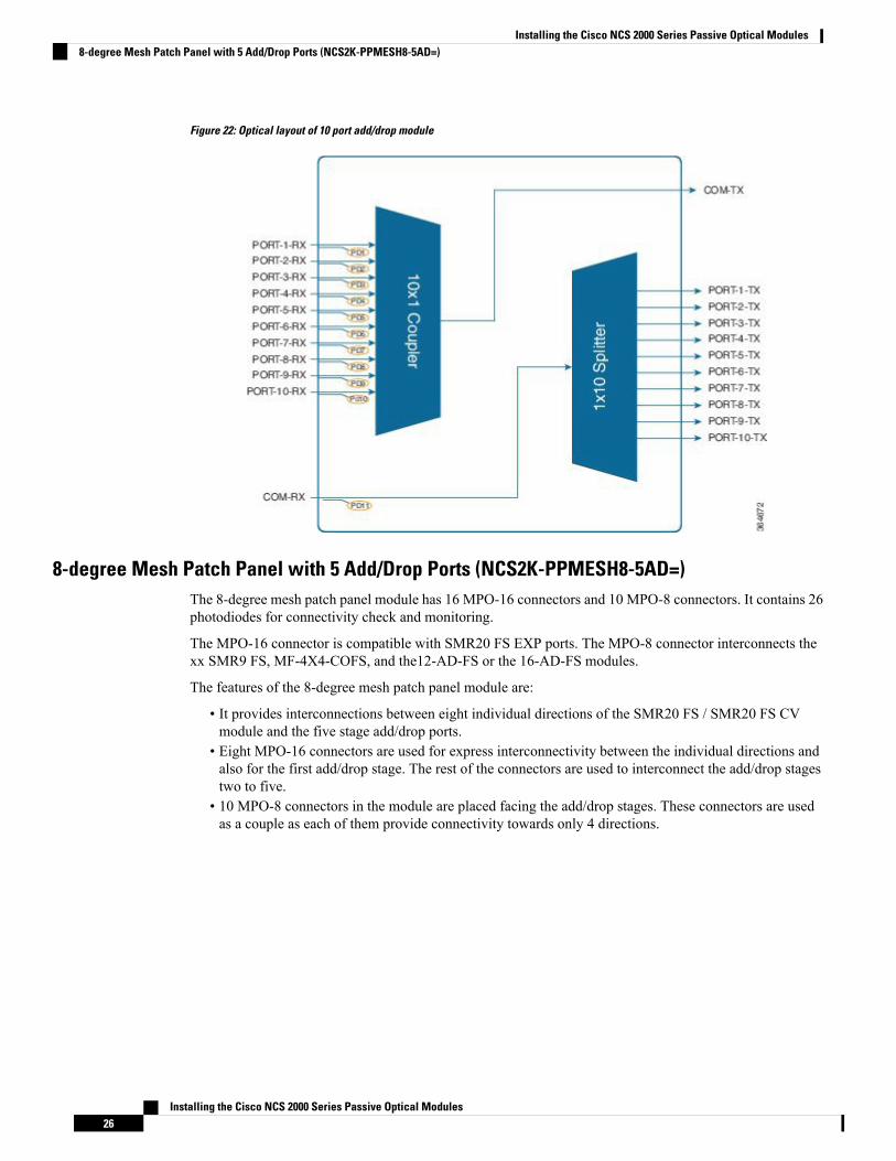
Figure 22: Optical layout of 10 port add/drop module
8-degree Mesh Patch Panel with 5 Add/Drop Ports (NCS2K-PPMESH8-5AD=)The 8-degree mesh patch panel module has 16 MPO-16 connectors and 10 MPO-8 connectors. It contains 26photodiodes for connectivity check and monitoring.
The MPO-16 connector is compatible with SMR20 FS EXP ports. The MPO-8 connector interconnects thexx SMR9 FS, MF-4X4-COFS, and the12-AD-FS or the 16-AD-FS modules.
The features of the 8-degree mesh patch panel module are:
• It provides interconnections between eight individual directions of the SMR20 FS / SMR20 FS CVmodule and the five stage add/drop ports.
• Eight MPO-16 connectors are used for express interconnectivity between the individual directions andalso for the first add/drop stage. The rest of the connectors are used to interconnect the add/drop stagestwo to five.
• 10 MPO-8 connectors in the module are placed facing the add/drop stages. These connectors are usedas a couple as each of them provide connectivity towards only 4 directions.
Installing the Cisco NCS 2000 Series Passive Optical Modules26
Installing the Cisco NCS 2000 Series Passive Optical Modules8-degree Mesh Patch Panel with 5 Add/Drop Ports (NCS2K-PPMESH8-5AD=)
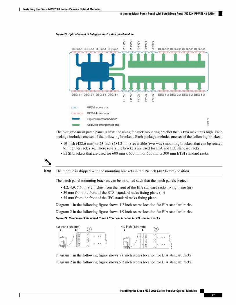
Figure 23: Optical layout of 8-degree mesh patch panel module
The 8-degree mesh patch panel is installed using the rack mounting bracket that is two rack units high. Eachpackage includes one set of the following brackets. Each package includes one set of the following brackets:
• 19-inch (482.6-mm) or 23-inch (584.2-mm) reversible (two-way) mounting brackets that can be rotatedto fit either rack size. These reversible brackets are used for EIA and IEC standard racks.
• ETSI brackets that are used for 600 mm x 600 mm or 600 mm x 300 mm ETSI standard racks.
The module is shipped with the mounting brackets in the 19-inch (482.6-mm) position.Note
The patch panel mounting brackets can be mounted such that the patch panels project:
• 4.2, 4.9, 7.6, or 9.2 inches from the front of the EIA standard racks fixing plane (or)• 39 mm from the front of the ETSI standard racks fixing plane (or)• 55 mm from the front of the IEC standard racks fixing plane
Diagram 1 in the following figure shows 4.2 inch recess location for EIA standard racks.
Diagram 2 in the following figure shows 4.9 inch recess location for EIA standard racks.Figure 24: 19-inch brackets with 4.2" and 4.9" recess location for EIA standard racks
Diagram 1 in the following figure shows 7.6 inch recess location for EIA standard racks.
Diagram 2 in the following figure shows 9.2 inch recess location for EIA standard racks.
Installing the Cisco NCS 2000 Series Passive Optical Modules27
Installing the Cisco NCS 2000 Series Passive Optical Modules8-degree Mesh Patch Panel with 5 Add/Drop Ports (NCS2K-PPMESH8-5AD=)

Figure 25: 19-inch brackets with 7.6" and 9.2" recess location for EIA standard racks
The following figure shows 39 mm recess location for ETSI standard racks.Figure 26: ETSI brackets with 39 mm recess location for ETSI standard racks
The following figure shows 55 mm recess location for IEC standard racks.Figure 27: 19-inch brackets with 55 mm recess location for IEC standard racks
Use only the fastening hardware provided with the 8-degree mesh patch panel to prevent loosening,deterioration, and electromechanical corrosion of the hardware and joined material.
Caution
When mounting the 8-degree mesh patch panel in a frame with a non-conductive coating (such as paint,lacquer, or enamel) use either the thread-forming screws provided with the shipping kit or remove the coatingfrom the threads to ensure electrical continuity.
Caution
It is recommended to configure the PPMESH8-5AD passive modules after configuring the other passivemodules. If any passive modules are configured after the PPMESH8-5AD module, the snmpwalk operationends without incrementing the error message OID. The checking of OID order must be disabled in SNMPmanager to avoid this error. For example, issue the following command from net-snmp: ./snmpwalk -v2c -cpublic -Cc IP address .1
Note
This procedure describes the steps to install the 8-degree mesh patch panel module.
Procedure
Step 1 Mount the brackets on the patch panel (see the Figure 29):
Installing the Cisco NCS 2000 Series Passive Optical Modules28
Installing the Cisco NCS 2000 Series Passive Optical Modules8-degree Mesh Patch Panel with 5 Add/Drop Ports (NCS2K-PPMESH8-5AD=)
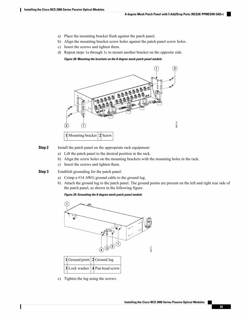
a) Place the mounting bracket flush against the patch panel.b) Align the mounting bracket screw holes against the patch panel screw holes.c) Insert the screws and tighten them.d) Repeat steps 1a through 1c to mount another bracket on the opposite side.
Figure 28: Mounting the brackets on the 8-degree mesh patch panel module
Screw2Mounting bracket1
Step 2 Install the patch panel on the appropriate rack equipment:a) Lift the patch panel to the desired position in the rack.b) Align the screw holes on the mounting brackets with the mounting holes in the rack.c) Insert the screws and tighten them.
Step 3 Establish grounding for the patch panel:a) Crimp a #14 AWG ground cable to the ground lug.b) Attach the ground lug to the patch panel. The ground points are present on the left and right rear side of
the patch panel, as shown in the following figure.Figure 29: Grounding the 8-degree mesh patch panel module
Ground lug2Ground point1
Pan head screw4Lock washer3
c) Tighten the lug using the screws.
Installing the Cisco NCS 2000 Series Passive Optical Modules29
Installing the Cisco NCS 2000 Series Passive Optical Modules8-degree Mesh Patch Panel with 5 Add/Drop Ports (NCS2K-PPMESH8-5AD=)
d) Terminate the other end of the ground cable either at the office ground point or the rack ground point.
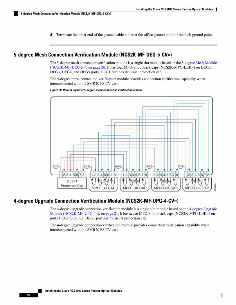
5-degree Mesh Connection Verification Module (NCS2K-MF-DEG-5-CV=)The 5-degree mesh connection verification module is a single slot module based on the 5-degreeMeshModule(NCS2K-MF-DEG-5=), on page 20. It has four MPO-8 loopback caps (NCS2K-MPO-LBK=) on DEG2,DEG3, DEG4, and DEG5 ports. DEG1 port has the usual protection cap.
The 5-degree mesh connection verification module provides connection verification capability wheninterconnected with the SMR20 FS CV card.Figure 30: Optical layout of 5-degree mesh connection verification module
4-degree Upgrade Connection Verification Module (NCS2K-MF-UPG-4-CV=)The 4-degree upgrade connection verification module is a single slot module based on the 4-degree UpgradeModule (NCS2K-MF-UPG-4=), on page 21. It has seven MPO-8 loopback caps (NCS2K-MPO-LBK=) onports DEG2 to DEG8. DEG1 port has the usual protection cap.
The 4-degree upgrade connection verification module provides connection verification capability wheninterconnected with the SMR20 FS CV card.
Installing the Cisco NCS 2000 Series Passive Optical Modules30
Installing the Cisco NCS 2000 Series Passive Optical Modules5-degree Mesh Connection Verification Module (NCS2K-MF-DEG-5-CV=)
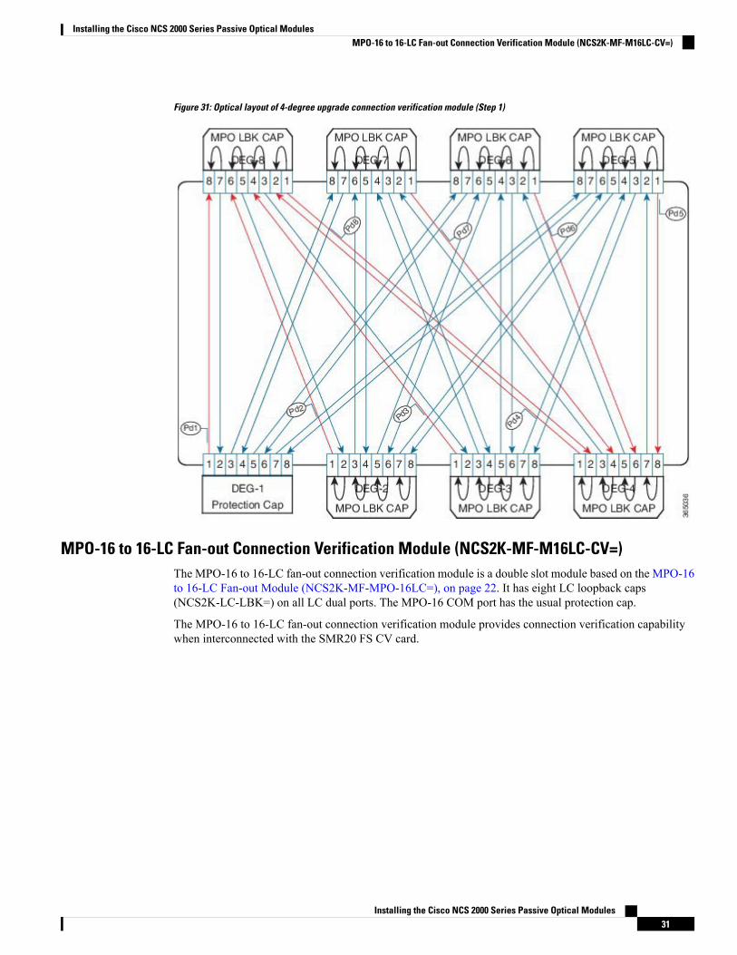
Figure 31: Optical layout of 4-degree upgrade connection verification module (Step 1)
MPO-16 to 16-LC Fan-out Connection Verification Module (NCS2K-MF-M16LC-CV=)The MPO-16 to 16-LC fan-out connection verification module is a double slot module based on the MPO-16to 16-LC Fan-out Module (NCS2K-MF-MPO-16LC=), on page 22. It has eight LC loopback caps(NCS2K-LC-LBK=) on all LC dual ports. The MPO-16 COM port has the usual protection cap.
The MPO-16 to 16-LC fan-out connection verification module provides connection verification capabilitywhen interconnected with the SMR20 FS CV card.
Installing the Cisco NCS 2000 Series Passive Optical Modules31
Installing the Cisco NCS 2000 Series Passive Optical ModulesMPO-16 to 16-LC Fan-out Connection Verification Module (NCS2K-MF-M16LC-CV=)
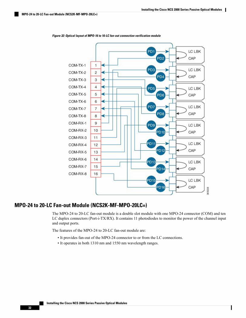
Figure 32: Optical layout of MPO-16 to 16-LC fan-out connection verification module
MPO-24 to 20-LC Fan-out Module (NCS2K-MF-MPO-20LC=)The MPO-24 to 20-LC fan-out module is a double slot module with one MPO-24 connector (COM) and tenLC duplex connectors (Port-i-TX/RX). It contains 11 photodiodes to monitor the power of the channel inputand output ports.
The features of the MPO-24 to 20-LC fan-out module are:
• It provides fan-out of the MPO-24 connector to or from the LC connections.• It operates in both 1310 nm and 1550 nm wavelength ranges.
Installing the Cisco NCS 2000 Series Passive Optical Modules32
Installing the Cisco NCS 2000 Series Passive Optical ModulesMPO-24 to 20-LC Fan-out Module (NCS2K-MF-MPO-20LC=)
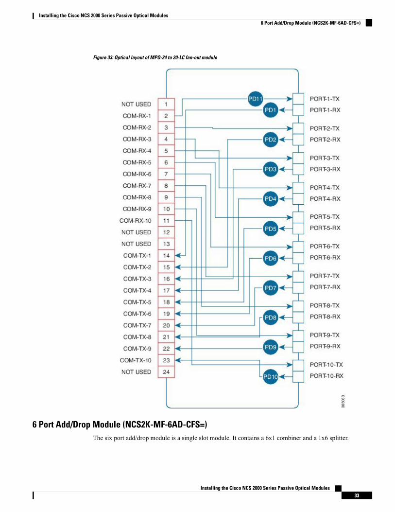
Figure 33: Optical layout of MPO-24 to 20-LC fan-out module
6 Port Add/Drop Module (NCS2K-MF-6AD-CFS=)The six port add/drop module is a single slot module. It contains a 6x1 combiner and a 1x6 splitter.
Installing the Cisco NCS 2000 Series Passive Optical Modules33
Installing the Cisco NCS 2000 Series Passive Optical Modules6 Port Add/Drop Module (NCS2K-MF-6AD-CFS=)

It contains seven embedded photodiodes for connectivity check andmonitoring at all the input ports (ADD-i-RX,and COM-RX). Virtual photodiodes are implemented at the output ports (DROP-i-TX, and COM-TX).
The features of the six port add/drop module are:
• It combines six channels from the ADD-i-RX ports into one signal at the COM-TX port.• It splits the optical signal from the COM-RX port into six identical signals at the DROP-i-TX ports.• It operates in the 1520 nm to 1570 nm wavelength range.
Figure 34: Optical Layout of Six Port Add/Drop Module
MPO-12 to 8-LC Fan-out Module (NCS2K-MF-8X10G-FO=)The MPO-12 to 8-LC fan-out module is a double slot module with two MPO-12 connector (COM) and eightLC duplex connectors (Port-i-TX/RX). It contains 16 photodiodes to monitor the power of the channel inputports.
The features of the MPO-12 to 8-LC fan-out module are:
• It provides fan-out of the MPO-12 connectors to or from eight LC-PC connections. There are twoindependent fan-out sections: COM-1 to PORT-i-1-TX/RX and COM-2 to PORT-i-2-TX/RX.
• It is used as client interconnection between two QSFP+ interfaces.• It splits 4x10G signals from the QSFP+ MPO cable into four single 10G bidirectional connections.• It operates in two wavelength ranges: 1260 nm to 1365 nm and 1520 nm to 1570 nm.
Installing the Cisco NCS 2000 Series Passive Optical Modules34
Installing the Cisco NCS 2000 Series Passive Optical ModulesMPO-12 to 8-LC Fan-out Module (NCS2K-MF-8X10G-FO=)

Figure 35: Optical Layout of MPO-12 to 8-LC Fan-out Module
Cisco NCS 2000 Series Passive Optical Modules SpecificationsThis section contains the environmental and mechanical specifications of the Cisco NCS 2000 Series passiveoptical modules.
Installing the Cisco NCS 2000 Series Passive Optical Modules35
Installing the Cisco NCS 2000 Series Passive Optical ModulesCisco NCS 2000 Series Passive Optical Modules Specifications
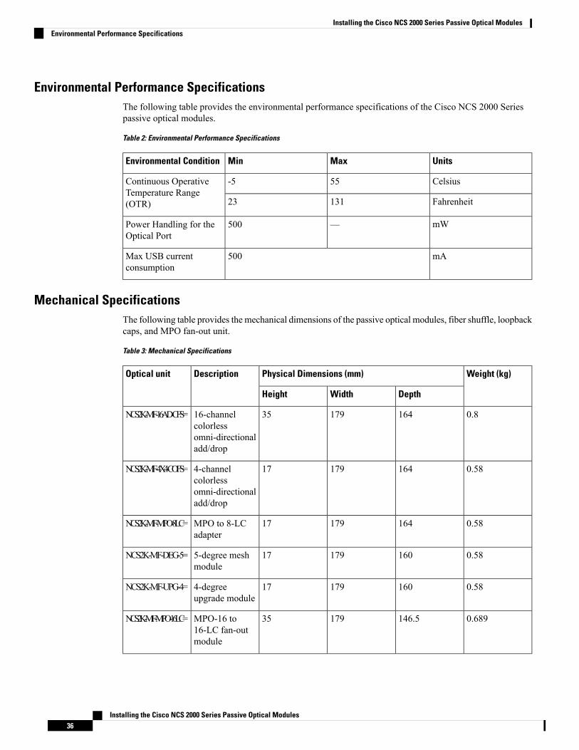
Environmental Performance SpecificationsThe following table provides the environmental performance specifications of the Cisco NCS 2000 Seriespassive optical modules.
Table 2: Environmental Performance Specifications
UnitsMaxMinEnvironmental Condition
Celsius55-5Continuous OperativeTemperature Range(OTR) Fahrenheit13123
mW—500Power Handling for theOptical Port
mA500Max USB currentconsumption
Mechanical SpecificationsThe following table provides the mechanical dimensions of the passive optical modules, fiber shuffle, loopbackcaps, and MPO fan-out unit.
Table 3: Mechanical Specifications
Weight (kg)Physical Dimensions (mm)DescriptionOptical unit
DepthWidthHeight
0.81641793516-channelcolorlessomni-directionaladd/drop
NCS2K-MF-16AD-CFS=
0.58164179174-channelcolorlessomni-directionaladd/drop
NCS2K-MF-4X4-COFS=
0.5816417917MPO to 8-LCadapter
NCS2K-MF-MPO-8LC=
0.58160179175-degree meshmodule
NCS2K-MF-DEG-5=
0.58160179174-degreeupgrade module
NCS2K-MF-UPG-4=
0.689146.517935MPO-16 to16-LC fan-outmodule
NCS2K-MF-MPO-16LC=
Installing the Cisco NCS 2000 Series Passive Optical Modules36
Installing the Cisco NCS 2000 Series Passive Optical ModulesEnvironmental Performance Specifications
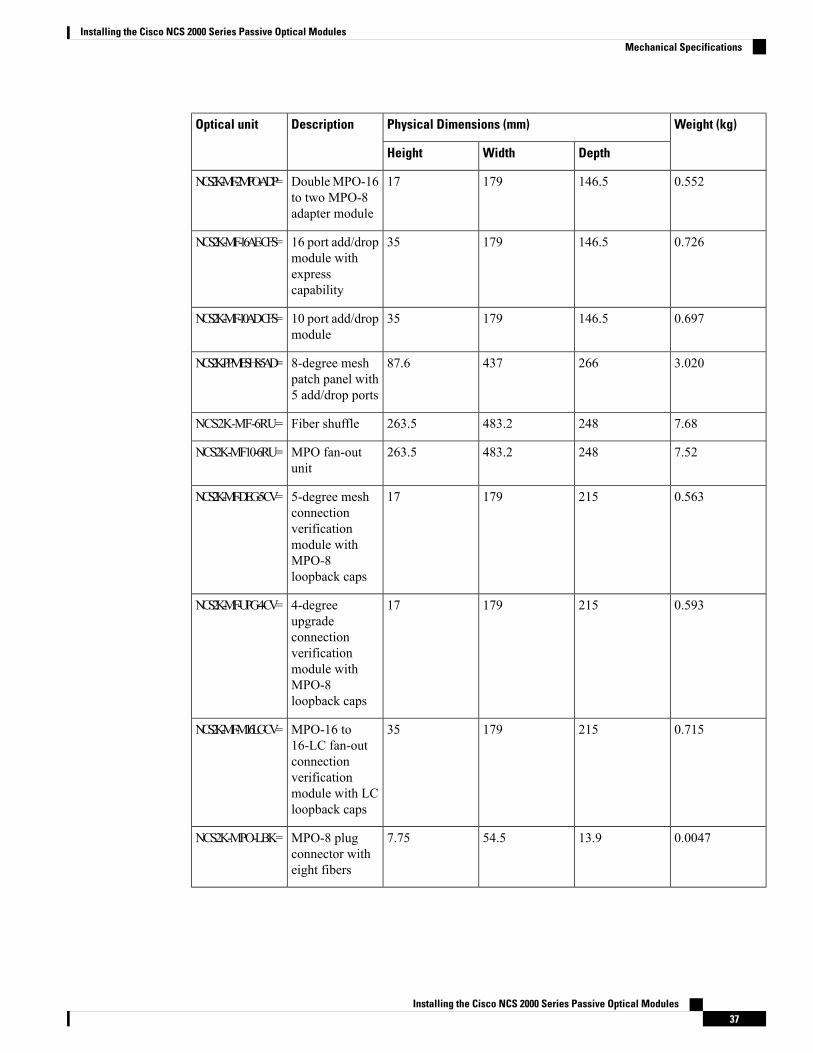
Weight (kg)Physical Dimensions (mm)DescriptionOptical unit
DepthWidthHeight
0.552146.517917DoubleMPO-16to two MPO-8adapter module
NCS2K-MF-2MPO-ADP=
0.726146.51793516 port add/dropmodule withexpresscapability
NCS2K-MF-16AE-CFS=
0.697146.51793510 port add/dropmodule
NCS2K-MF-10AD-CFS=
3.02026643787.68-degree meshpatch panel with5 add/drop ports
NCS2K-PPMESH8-5AD=
7.68248483.2263.5Fiber shuffleNCS2K-MF-6RU=
7.52248483.2263.5MPO fan-outunit
NCS2K-MF10-6RU=
0.563215179175-degree meshconnectionverificationmodule withMPO-8loopback caps
NCS2K-MF-DEG-5-CV=
0.593215179174-degreeupgradeconnectionverificationmodule withMPO-8loopback caps
NCS2K-MF-UPG-4-CV=
0.71521517935MPO-16 to16-LC fan-outconnectionverificationmodule with LCloopback caps
NCS2K-MF-M16LC-CV=
0.004713.954.57.75MPO-8 plugconnector witheight fibers
NCS2K-MPO-LBK=
Installing the Cisco NCS 2000 Series Passive Optical Modules37
Installing the Cisco NCS 2000 Series Passive Optical ModulesMechanical Specifications

Weight (kg)Physical Dimensions (mm)DescriptionOptical unit
DepthWidthHeight
0.004715359.2UPC LC plugdual connectorwith internalinterconnectionbetween twoports
NCS2K-LC-LBK=
0.65921517935MPO-24 to20-LC fan-outmodule
NCS2K-MF-MPO-20LC=
0.716517917six port add/dropmodule
NCS2K-MF-6AD-CFS=
116517935MPO-12 to 8-LCfan-out module
NCS2K-MF-8X10G-FO=
InstallationThis section explains how to:
• Unpack and Verify the Rack Mounting Bracket and Optical Modules, on page 38• Install the Rack Mounting Bracket, on page 39• Install the Optical Module, on page 41
Unpack and Verify the Rack Mounting Bracket and Optical ModulesThe rack mounting bracket and the optical modules are shipped in separate packages. This procedure describesthe steps for unpacking and verifying both the components.
Procedure
Step 1 Unpack and inspect the rack mounting bracket and optical modules.
The rack mounting bracket package should include these components with the quantity of the item (specifiedin parentheses), included in the package.
• 19-inch ANSI/IEC rack mounting bracket assembled with 3 filler panels• Straight external brackets for 23-inch ANSI installation (2)• Z-shaped external brackets for ETSI installation (2)• #12-24 x 0.50 pan-head Phillips screws (4)• #12 lock washers (4)• M6 x12 pan-head Phillips screws (8)• Lock washers for M6 screws (8)• Velcro strips for fiber management (4)
Installing the Cisco NCS 2000 Series Passive Optical Modules38
Installing the Cisco NCS 2000 Series Passive Optical ModulesInstallation

• Tie-wraps for locking the inventory USB plug cable (2)• Production test report form showing the part number and serial number of the manufacturer, Cisco productpart number, date, and device description
• Packing slip
The optical module package should include the following components:
• Optical modules• Production test report form showing the part number and serial number of the manufacturer, Cisco productpart number, date, and device description
• Packing slip
Step 2 Compare the equipment received with the packing slip and the equipment list that customer service provided.If there are any discrepancies, notify the Customer Service Center.
Step 3 Check for external damage. Visually check all components and immediately report any shipping damage toyour customer service representative. Have this information ready:
• Invoice number of shipper (see packing slip)• Model and serial number of the damaged unit• Description of damage• Effect of damage on the installation• Packing slip
Install the Rack Mounting BracketThis procedure explains how to install the rackmounting bracket to the ANSI, IEC, or ETSI standard equipmentrack.
Procedure
Step 1 Insert the tie-wraps on both sides of the rack mounting bracket.Step 2 To mount the rack mounting bracket to the standard equipment rack:
• For a 19-inch (482.6-mm) ANSI or IEC configuration, align the rack mounting bracket screw holesagainst the equipment rack screw holes (see the following figure).
Installing the Cisco NCS 2000 Series Passive Optical Modules39
Installing the Cisco NCS 2000 Series Passive Optical ModulesInstall the Rack Mounting Bracket
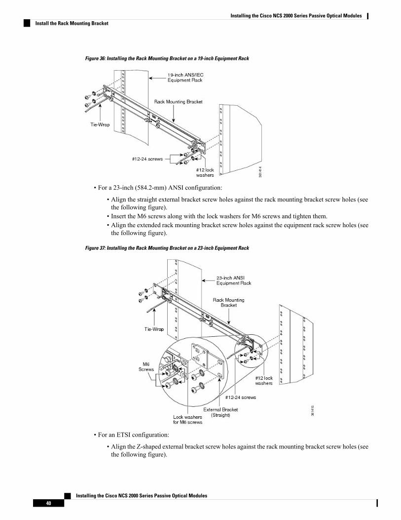
Figure 36: Installing the Rack Mounting Bracket on a 19-inch Equipment Rack
• For a 23-inch (584.2-mm) ANSI configuration:
• Align the straight external bracket screw holes against the rack mounting bracket screw holes (seethe following figure).
• Insert the M6 screws along with the lock washers for M6 screws and tighten them.• Align the extended rack mounting bracket screw holes against the equipment rack screw holes (seethe following figure).
Figure 37: Installing the Rack Mounting Bracket on a 23-inch Equipment Rack
• For an ETSI configuration:
• Align the Z-shaped external bracket screw holes against the rack mounting bracket screw holes (seethe following figure).
Installing the Cisco NCS 2000 Series Passive Optical Modules40
Installing the Cisco NCS 2000 Series Passive Optical ModulesInstall the Rack Mounting Bracket

• Insert the M6 screws along with the lock washers for M6 screws and tighten them.• Align the extended rack mounting bracket screw holes against the equipment rack screw holes (seethe following figure).
Figure 38: Installing the Rack Mounting Bracket on an ETSI Equipment Rack
Step 3 Insert the screws along with the lock washers and tighten them.
Install the Optical ModuleThis procedure explains how to install the optical module into the rack mounting bracket.
Procedure
Step 1 Install the rack mounting bracket on the equipment rack by following the steps described in the Install theRack Mounting Bracket, on page 39.
Step 2 Identify the slot in the rack mounting bracket to install the optical module.
The rackmounting bracket has two cut outs. Each cut out (left or right) can accommodate two singleslot cassettes, for a total of four single slot cassettes in the rack mounting bracket. Each cut out (leftor right) can also accommodate one double slot cassette, for a total of two double slot cassettes inthe rack mounting bracket. If a rack mounting bracket slot remains empty, it can be filled with ablank-slot filler panels.
Note
Step 3 Loosen the captive screws to remove the filler panel from the rack mounting bracket (see the following figure).
Installing the Cisco NCS 2000 Series Passive Optical Modules41
Installing the Cisco NCS 2000 Series Passive Optical ModulesInstall the Optical Module

Figure 39: Removing the Filler Panel from the Rack Mounting Bracket
Step 4 Insert the optical module into the empty slot (see the following figure).Figure 40: Installing the Optical Module into the Rack Mounting Bracket
Step 5 Tighten the captive screws of the optical module to fix them into the rack mounting bracket (see the followingfigure).
Installing the Cisco NCS 2000 Series Passive Optical Modules42
Installing the Cisco NCS 2000 Series Passive Optical ModulesInstall the Optical Module

Figure 41: Optical Modules installed
Step 6 To connect the fibers as appropriate:a) Remove the LC orMPO dust cap from the LC-LC orMPO-MPO adapter of the optical module respectively.b) Route the optical patch cords with the LC or MPO connectors to the optical module.
Refer to the port label description and channel identification port information of the optical module. Forfibering instructions, see the Fiber-Optic Connector Cleaning andMaintenance, on page 44 and the Installand Route Fiber-Optic Cables, on page 46.
Step 7 Connect the inventory USB Type A plug connector of the USB cable to the inventory USB Type A receptaclepresent on the optical module. To secure the USB cable and the fiber patchcords, lock it with the tie-wrap.
The fibers and the USB cable can also be connected to the optical modules before installing themin the rack mounting bracket. This is more suitable in an ETSI environment or when there are othermodules preinstalled in the equipment rack.
Note
Ground DescriptionThe unpainted surface between the rack mounting bracket and optical modules, ensure proper grounding ofthe passive optical module (see the following figure). The rack mounting bracket, the straight external brackets,and the Z-shaped external brackets are unpainted and treated with conductive finishing.
Installing the Cisco NCS 2000 Series Passive Optical Modules43
Installing the Cisco NCS 2000 Series Passive Optical ModulesGround Description
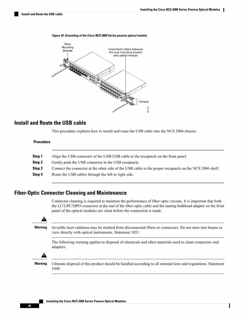
Figure 42: Grounding of the Cisco NCS 2000 Series passive optical module
Install and Route the USB cableThis procedure explains how to install and route the USB cable into the NCS 2006 chassis.
Procedure
Step 1 Align the USB connector of the USB-USB cable to the receptacle on the front panel.Step 2 Gently push the USB connector in the USB receptacle.Step 3 Connect the connector at the other side of the USB cable to the proper receptacle on the NCS 2006 shelf.Step 4 Route the USB cables through the left or right side.
Fiber-Optic Connector Cleaning and MaintenanceConnector cleaning is required to maintain the performance of fiber-optic circuits. It is important that boththe LC/UPC/MPO connector at the end of the fiber-optic cable and the mating bulkhead adapter on the frontpanel of the optical modules are clean before the connection is made.
Invisible laser radiation may be emitted from disconnected fibers or connectors. Do not stare into beams orview directly with optical instruments. Statement 1051
Warning
The following warning applies to disposal of chemicals and other materials used to clean connectors andadapters:
Ultimate disposal of this product should be handled according to all national laws and regulations. Statement1040
Warning
Installing the Cisco NCS 2000 Series Passive Optical Modules44
Installing the Cisco NCS 2000 Series Passive Optical ModulesInstall and Route the USB cable
Before installing the fiber-optic cable, always perform the cleaning procedure for cable connectors describedin the following section.Whenever possible, inspect each connector before connecting it to the mating bulkheadadapter on the front panel.
The LC/MPO bulkhead adapters on the optical modules are less likely to get dirty if they are capped whennot in use. Because the procedure for a thorough cleaning of these adapters is complicated, we recommendthat you use a commercially available cleaning kit and closely follow the instructions included with the kit.
Customer Supplied Cleaning MaterialsThe Type A fiber-optic connector cleaners (for example, CLETOP reel) are recommended to clean the cableconnectors, but are not supplied with the passive optical modules.
When cleaning a paired cable connector (bulkhead mating adapter), always clean the mating adapter first.
If properly maintained (only used with clean, defect-free fiber connectors and capped when not in use), themating adapter would not require cleaning. However, if you suspect the adapter is dirty, clean it by using theCLETOP stick swab.
For multi-fiber cable assemblies, use specific cleaning tools or materials designed for the assembly type.Note
Clean the Bulkhead Mating AdaptersThis procedure explains how to clean the bulkhead mating adapters.
Procedure
Step 1 Read the manufacturer (cleaning cartridge) instructions to insert the cartridge cleaning tip into the matingadapter.
Step 2 Slide the lever on the cartridge to swipe the mating surface.
Always keep unused adapter ports and fiber connectors capped with a clean dust cap.Note
Clean Fiber-Optic Cable ConnectorsThe tools required to clean fiber-optic cable connectors are:
• Inspection microscope• Type A fiber-optic connector cleaner (CLETOP reel)• Optical swab• Optical receiver cleaning stick
Procedure
Step 1 Using an inspection microscope, inspect each fiber connector for dirt, cracks, or scratches.Step 2 Replace any damaged fiber connectors.
Installing the Cisco NCS 2000 Series Passive Optical Modules45
Installing the Cisco NCS 2000 Series Passive Optical ModulesCustomer Supplied Cleaning Materials

Replace all dust caps whenever the equipment is unused for 30 minutes or more.Note
Do not reuse optical swabs. Keep unused swabs away from work surfaces.Note
Step 3 Clean the fiber connectors with CLETOP reel:a) Remove the dust cap from the fiber connector.b) Press the lever down to open the shutter door. Each time you press the lever, you expose a clean wiping
surface.c) Insert the connector into the CLETOP cleaning cassette slot, rotate one quarter turn, and gently swipe
downwards.d) Use an inspection microscope to inspect each fiber connector for dirt, cracks, or scratches. If the connector
is not clean, repeat Steps to .e) Insert the fiber connector into the applicable adapter or attach a dust cap to the fiber connector.
If you must replace a dust cap on a connector, first verify that the dust cap is clean. To cleanthe dust cap, wipe the outside of the cap using a dry lint-free wipe and the inside of it using aCLETOP stick swab (14100400).
Note
Install and Route Fiber-Optic Cables
Invisible laser radiation may be emitted from disconnected fibers or connectors. Do not stare into beams orview directly with optical instruments. Statement 1051
Warning
When connecting an optical fiber patch cord between the optical module and the optical card ports in theCisco NCS, use the electrostatic discharge wristband supplied with the Cisco NCS. Plug the wristband intothe ESD jack on the lower right front side of the Cisco NCS.
Caution
Always clean all fiber connectors thoroughly before making the connection with the mating adapter. Verysmall particles can permanently damage the end of the mating fiber inside the optical module, which makesregular cleaning imperative. For cleaning instructions see Fiber-Optic Connector Cleaning and Maintenance,on page 44.
Note
The optical modules feature LC/UPC/MPO bulkhead adapters. Always use fiber-optic cables equipped withthe corresponding (LC/UPC/MPO) connector type. Using any other type of connector results in damage tothe connector or adapter, or both.
Note
This procedure explains how to install and route fiber-optic cables.
Installing the Cisco NCS 2000 Series Passive Optical Modules46
Installing the Cisco NCS 2000 Series Passive Optical ModulesInstall and Route Fiber-Optic Cables

Procedure
Step 1 Place the LC/UPC/MPO cable connector in front of the corresponding bulkhead adapter on the front panelof the optical modules.
Step 2 Align the keyed ridge of the cable connector with the slot in the receiving adapter.Step 3 Gently push the cable connector into the adapter until you hear a click, which indicates that the latching system
is engaged.Step 4 Route the fiber cables through the left or right side.
What to do next
If high connection density in the optical modules (that are plugged into the same rack mounting bracket oroptical modules assembled in the rack mounting bracket immediately above or below) causes difficulties tothe operator in the proper handling of the optical connectors, the specific optical module has to be removedfrom the rack mounting bracket, fully connected with proper optical connectors, USB cable and thenreassembled into the rack mounting bracket.
Note
Uninstalling the ModuleThis procedure describes the steps for removing the optical modules from the rack.
Procedure
Step 1 Remove the fibers and the cable from the optical modules.Step 2 Disconnect the inventory USB cable from the USB receptacle.Step 3 Loosen the captive screws of the optical modules.Step 4 Extract the optical modules from the rack mounting bracket.Step 5 Loosen the screws of the rack mounting bracket.Step 6 Remove the rack mounting bracket from the equipment rack.
What to do next
If it is not possible to remove the optical connectors due to high connection density in step 1, unplug theoptical module as per step 3 and step 4. Now, the optical connectors and the USB cable can be disconnectedeasily.
Note
Installing the Cisco NCS 2000 Series Passive Optical Modules47
Installing the Cisco NCS 2000 Series Passive Optical ModulesUninstalling the Module
Related DocumentationUse the Installing the Cisco NCS 2000 Series Passive Optical Modules document in conjunction with thefollowing referenced publications:
• Cisco NCS 2000 Series Control Card and Node Configuration Guide• Cisco NCS 2000 Series Line Card Configuration Guide• Cisco NCS 2000 Series Network Configuration Guide• Cisco NCS 2000 Series Troubleshooting Guide
Visit the End-of-Life and End-of-Sale Notices page for EOL and EOS announcements.
Obtaining Documentation and Submitting a Service RequestFor information on obtaining documentation, submitting a service request, and gathering additional information,see the monthlyWhat’s New in Cisco Product Documentation, which also lists all new and revised Ciscotechnical documentation, at:
http://www.cisco.com/en/US/docs/general/whatsnew/whatsnew.html
Subscribe to theWhat’s New in Cisco Product Documentation as a Really Simple Syndication (RSS) feedand set content to be delivered directly to your desktop using a reader application. The RSS feeds are a freeservice and Cisco currently supports RSS Version 2.0.
Installing the Cisco NCS 2000 Series Passive Optical Modules48
Installing the Cisco NCS 2000 Series Passive Optical ModulesRelated Documentation