installer instructions for alphaeclipse roadstar signs instructions for alphaeclipse roadstar signs...
TRANSCRIPT

Installer Instructions for AlphaEclipse RoadStar Signs(Form number 9717-5021, November 9, 2005)
Instructions
for the
Sign Installer© Copyright 2005 Adaptive Micro Systems LLC. All rights reserved.Adaptive Micro Systems, 7840 North 86th Street, Milwaukee, WI 53224 USA 414-357-2020, 414-357-2029 (fax)http://www.adaptivedisplays.comTrademarked names appear throughout this document. Rather than list the names and entities that own the trademarks or insert a trademark symbol with each mention of the trademarked name, the publisher states that it is using names for
editorial purposes and to the benefit of the trademark owner with no intention of improperly using the trademark. The following are trademarks of Adaptive Micro Systems: Adaptive, Alpha, AlphaLert, AlphaNET, AlphaNet plus, AlphaEclipse, AlphaEclipse RoadStar, AlphaEclipse StreetSmart, AlphaPremiere, AlphaTicker, AlphaVision, AlphaVision InfoTracker, AlphaXpress, Automode, BetaBrite, BetaBrite Director, BetaBrite Messaging Software, Big Dot, Director, EZ KEY II, EZ95, PagerNET, PPD, PrintPak, Serial Clock, Smart Alec, Solar, TimeNet.
The distinctive trade dress of this product is a trademark claimed by Adaptive Micro Systems LLC. Due to continuing product innovation, specifications in this manual are subject to change without notice.
,
Installer Instructions for AlphaEclipse RoadStar signs (Form no. 9717-5021 November 9, 2005
TABLE ANCHOR - CHANGE THIS STYLE TO TINY TO MAKE THE TABLE FLUSH
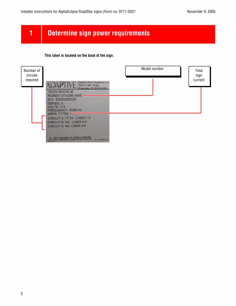
1 Determine sign power requirements
Number of circuits required
Model number Totalsign
current
This label is located on the back of the sign.
2

November 9, 2005 Installer Instructions for AlphaEclipse RoadStar signs (Form no. 9717-5021
TABLE ANCHOR - CHANGE THIS STYLE TO TINY TO MAKE THE TABLE FLUSH
2 Mount sign
Observe safety precautions
OverviewBecause every sign installation is unique, there is no single procedure for mounting AlphaEclipse RoadStar
signs. However, sign sections must be supported (affixed to superstructure able to withstand live loads and comply with all national and local codes) prior to assembling the sections or opening the doors, otherwise sign may tip causing serious injury. Additionally, sign parts could sustain damage if the doors are opened and the sign is not fully off the ground. Failure to comply will void the sign’s warranty.
This section is only intended as a guide.
• Drill holes as needed in the sign’s steel framework for fasteners. Drilling holes in any of the excluded areas will void the sign’s warranty. When drilling holes, follow these guidelines:
• Connections must be analyzed by a structural engineer.• Dissimilar metals must be isolated to avoid galvanic corrosion.• Any area on the sign’s frame that had paint removed during mounting must be recoated with paint that is
UL recognized to standard UL-1332, category DTOV2. Failure to repaint the area will result in accelerated corrosion of the sign’s structure. Adaptive Micro Systems is not responsible for any failure in the sign’s structure because of this. Failure to comply will void the sign’s warranty.
Support structure designThe design of a sign’s support structure depends on a number of factors:
• mounting methods• building codes• foundation• sign size• sign weight• sign height• wind loading• seismic loading
All installations, superstructure designs, and connections must be designed and approved by a qualified structural engineer. Call Adaptive Micro Systems at 1-800-558-7022 for contact information for structural engineering consultants.
3

Installer Instructions for AlphaEclipse RoadStar signs (Form no. 9717-5021 November 9, 2005
TABLE ANCHOR — CHANGE THIS STYLE TO TINY TO MAKE THE TABLE FLUSH
3 Mount sign (continued)
Observe safety precautions
Sign mounting guidelinesThe AlphaEclipse Roadstar sign uses modular section design. Signs longer than 48
columns are shipped in two or more sections. These sections are joined together by the sign installer onto a superstructure designed to withstand live loads and comply with all national and local codes. Live loads include loading from wind and seismic events.
The method used to mount signs varies greatly from location to location. The installer must ensurethat installation will adequately meet local codes and standards.
The customer must have a qualified structural engineer review the structure and attachment points to the superstructure. The back of the sign uses a 2” x 2” x .13” (64mm pitch signs) or 2” x 3” x .13” (89mm pitch signs) steel angle. These angles assist in mounting the sign.
The angles at the back of the sign andeyebolts are only designed to lift one section at a time.
• DO NOT use the lifting hardware to pick up multiple sections. • DO NOT join multiple sections together with a short “coupling” bar. This will not provide adequate
strength for lifting or live loading. All sections must be installed onto a superstructure designed to withstand live loads and comply with all national and local codes.
• DO NOT use the eyebolts to pick up the sign and customer-installed superstructure. • DO NOT use the eyebolts to pick up two setions.Failure to follow these instructions will void warranty.
4

November 9, 2005 Installer Instructions for AlphaEclipse RoadStar signs (Form no. 9717-5021
TABLE ANCHOR — CHANGE THIS STYLE TO TINY TO MAKE THE TABLE FLUSH
Lifting the sign
5

Installer Instructions for AlphaEclipse RoadStar signs (Form no. 9717-5021 November 9, 2005
BLUE
3 Ventilation requirements
At the top and bottom of a sign allow 4” of obstruction free space. For signs longer than 10’ add an additional 4” of obstruction free space every additional 10’ of sign.
The distance from the back of a sign to a solid surface must be 5” for the first 10’ of sign and an additional 1” for every 10” of sign.
6

November 9, 2005 Installer Instructions for AlphaEclipse RoadStar signs (Form no. 9717-5021
BLUE
4 Sign assembly
• Start assembling the sign with the Control Section, Section A1.
• Assemble one row at a time.• Assemble Row 1 before stacking
second row.• Your sign may look different than
this example.
7
Installer Instructions for AlphaEclipse RoadStar signs (Form no. 9717-5021 November 9, 2005
BLUE
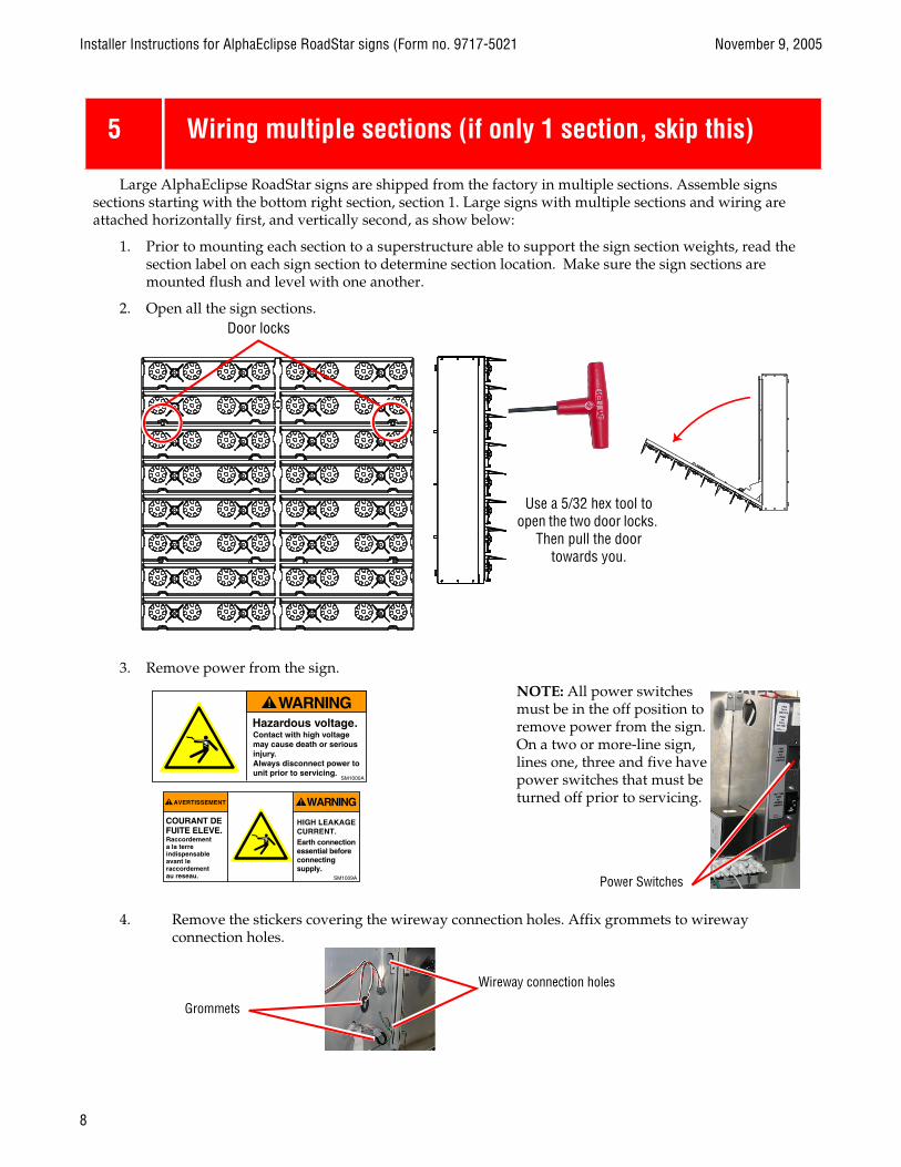
5 Wiring multiple sections (if only 1 section, skip this)
Large AlphaEclipse RoadStar signs are shipped from the factory in multiple sections. Assemble signs sections starting with the bottom right section, section 1. Large signs with multiple sections and wiring are attached horizontally first, and vertically second, as show below:
1. Prior to mounting each section to a superstructure able to support the sign section weights, read the section label on each sign section to determine section location. Make sure the sign sections are mounted flush and level with one another.
2. Open all the sign sections.
3. Remove power from the sign.
4. Remove the stickers covering the wireway connection holes. Affix grommets to wireway connection holes.
Door locks
Use a 5/32 hex tool to open the two door locks.
Then pull the door towards you.
NOTE: All power switches must be in the off position to remove power from the sign. On a two or more-line sign, lines one, three and five have power switches that must be turned off prior to servicing.
Power Switches
Wireway connection holes
Grommets
8
November 9, 2005 Installer Instructions for AlphaEclipse RoadStar signs (Form no. 9717-5021
BLUEBLUEBLUE
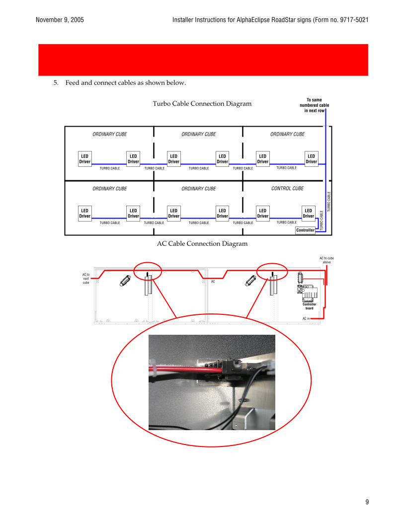
5. Feed and connect cables as shown below.
Turbo Cable Connection Diagram
AC Cable Connection Diagram
9

Installer Instructions for AlphaEclipse RoadStar signs (Form no. 9717-5021 November 9, 2005
6 Wire signs together (continued)
MASTER / SECONDARY MASTER• If your signs have these
two labels, you have a master/secondary master sign configuration.
10
November 9, 2005 Installer Instructions for AlphaEclipse RoadStar signs (Form no. 9717-5021
BLUE
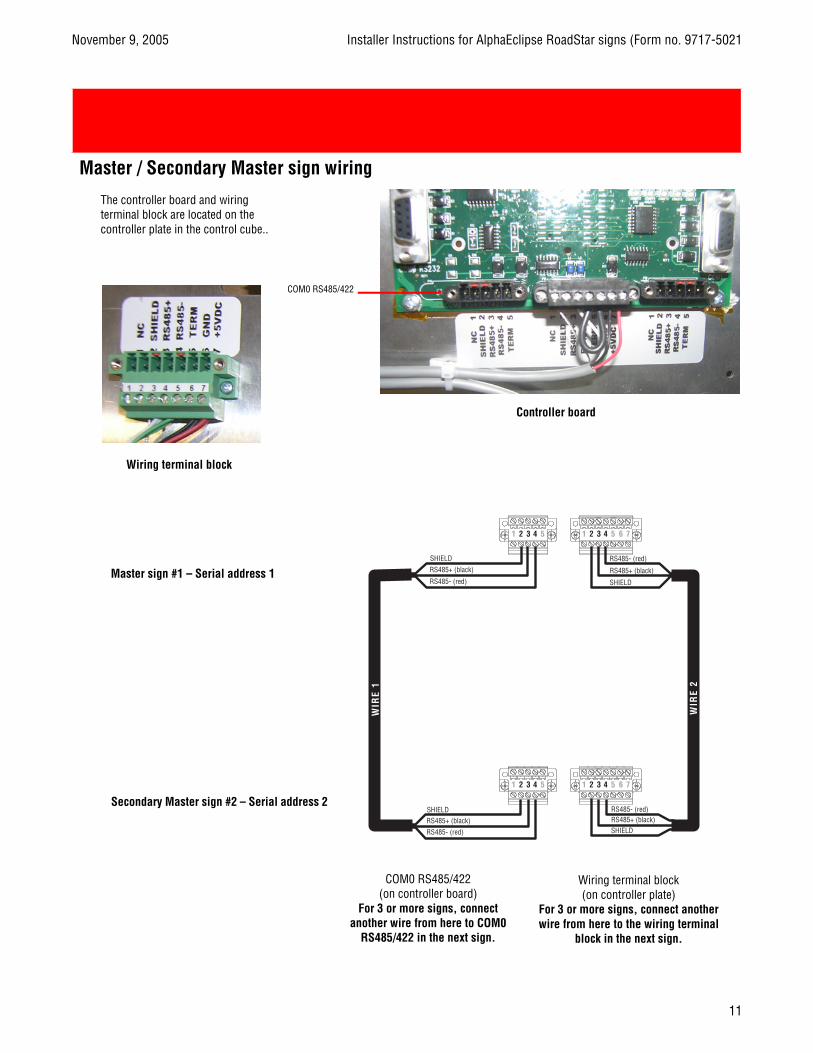
Master / Secondary Master sign wiring
Wiring terminal block (on controller plate)
For 3 or more signs, connect another wire from here to the wiring terminal
block in the next sign.
COM0 RS485/422(on controller board)
For 3 or more signs, connect another wire from here to COM0
RS485/422 in the next sign.
Master sign #1 – Serial address 1
COM0 RS485/422
Controller board
The controller board and wiring terminal block are located on the controller plate in the control cube..
Wiring terminal block
Secondary Master sign #2 – Serial address 2
11

Installer Instructions for AlphaEclipse RoadStar signs (Form no. 9717-5021 November 9, 2005
6 Wire signs together (continued)
MASTER / SECONDARY MASTER• If your signs have these
two labels, you have a master/slave sign configuration.
12

November 9, 2005 Installer Instructions for AlphaEclipse RoadStar signs (Form no. 9717-5021
BLUE
Master / Slave sign wiring
Controller board
Wiring terminal block
The controller board and wiring terminal block are located on the controller plate in the control cube.
COM0 RS485/422
Slave sign #2 – Serial address 2
Master sign #1 – Serial address 1
COM0 RS485/422(on controller board)
For 3 or more signs, connect another wire from here to COM0
RS485/422 in the next sign.
Wiring terminal block (on controller plate)
For 3 or more signs, connect another wire from here to the wiring terminal
block in the next sign.
COM3 RS485
13
Installer Instructions for AlphaEclipse RoadStar signs (Form no. 9717-5021 November 9, 2005
BLUE
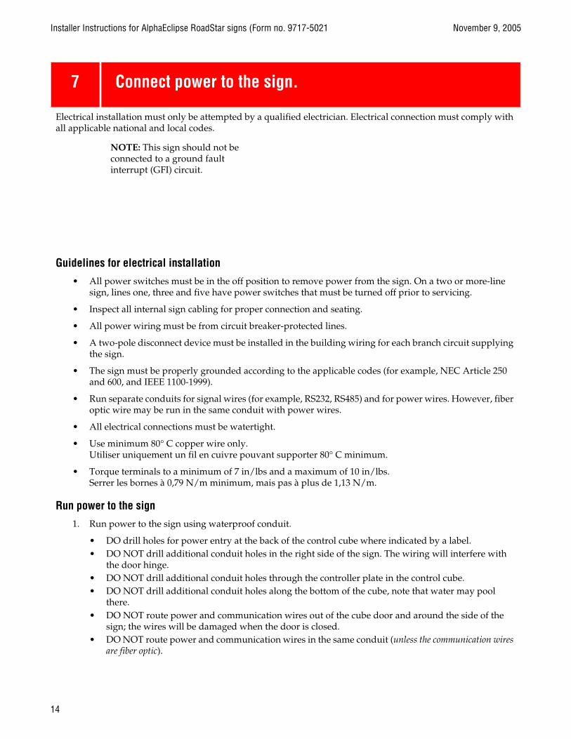
7 Connect power to the sign.
Electrical installation must only be attempted by a qualified electrician. Electrical connection must comply with all applicable national and local codes.
Guidelines for electrical installation
• All power switches must be in the off position to remove power from the sign. On a two or more-line sign, lines one, three and five have power switches that must be turned off prior to servicing.
• Inspect all internal sign cabling for proper connection and seating.
• All power wiring must be from circuit breaker-protected lines.
• A two-pole disconnect device must be installed in the building wiring for each branch circuit supplying the sign.
• The sign must be properly grounded according to the applicable codes (for example, NEC Article 250 and 600, and IEEE 1100-1999).
• Run separate conduits for signal wires (for example, RS232, RS485) and for power wires. However, fiber optic wire may be run in the same conduit with power wires.
• All electrical connections must be watertight.
• Use minimum 80° C copper wire only.Utiliser uniquement un fil en cuivre pouvant supporter 80° C minimum.
• Torque terminals to a minimum of 7 in/lbs and a maximum of 10 in/lbs.Serrer les bornes à 0,79 N/m minimum, mais pas à plus de 1,13 N/m.
Run power to the sign
1. Run power to the sign using waterproof conduit.
• DO drill holes for power entry at the back of the control cube where indicated by a label.• DO NOT drill additional conduit holes in the right side of the sign. The wiring will interfere with
the door hinge.• DO NOT drill additional conduit holes through the controller plate in the control cube. • DO NOT drill additional conduit holes along the bottom of the cube, note that water may pool
there.• DO NOT route power and communication wires out of the cube door and around the side of the
sign; the wires will be damaged when the door is closed. • DO NOT route power and communication wires in the same conduit (unless the communication wires
are fiber optic).
NOTE: This sign should not be connected to a ground fault interrupt (GFI) circuit.
14

November 9, 2005 Installer Instructions for AlphaEclipse RoadStar signs (Form no. 9717-5021
BLUE
(This page intentionally left blank)
15
Installer Instructions for AlphaEclipse RoadStar signs (Form no. 9717-5021 November 9, 2005
TABLE ANCHOR — CHANGE THIS STYLE TO TINY TO MAKE THE TABLE FLUSH
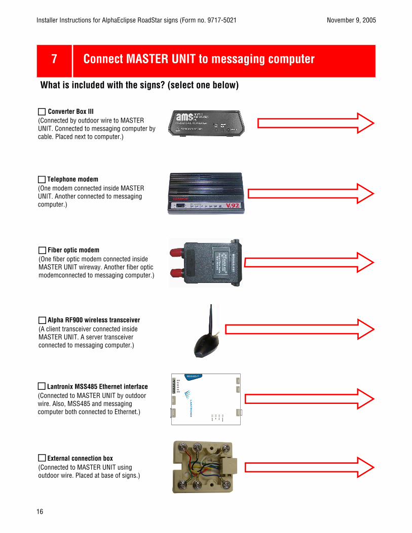
7 Connect MASTER UNIT to messaging computer
What is included with the signs? (select one below)
Converter Box III(Connected by outdoor wire to MASTER UNIT. Connected to messaging computer by cable. Placed next to computer.)
Telephone modem(One modem connected inside MASTER UNIT. Another connected to messaging computer.)
Fiber optic modem(One fiber optic modem connected inside MASTER UNIT wireway. Another fiber optic modemconnected to messaging computer.)
Alpha RF900 wireless transceiver(A client transceiver connected inside MASTER UNIT. A server transceiver connected to messaging computer.)
LA
NT
RO
NIX
MSS485-T
serialco
nso
le
shldtxatxbrxbrxashld
6vd
cre
set
10B
AS
E-T
po
wer
link
ok
serial
Lantronix MSS485 Ethernet interface(Connected to MASTER UNIT by outdoor wire. Also, MSS485 and messaging computer both connected to Ethernet.)
External connection box(Connected to MASTER UNIT using outdoor wire. Placed at base of signs.)
16

November 9, 2005 Installer Instructions for AlphaEclipse RoadStar signs (Form no. 9717-5021
TABLE ANCHOR — CHANGE THIS STYLE TO TINY TO MAKE THE TABLE FLUSH
AlphaEclipse RoadStar sign
Messaging computer runningAlphaNET software
up to 4000 feet 10 feet
RS485 plenum cable RS232 cable(pn 7124-0203) (pn 1088-8634)
Converter Box III(pn 1088-1111)
AlphaEclipse RoadStar sign
Fiber optic mini-modems(pn 1051-9016)
Messaging computerrunning AlphaNET software
up to 2 miles
Fiber optic cables
RXTX
DATA
RXTX
DATA
DB9-to-DB9cable
DB25-to-DB9adapter
Alpha RF900 ServerClient transceiver (inside sign)
RS232 cable(supplied with transceiver)
Messaging computerrunning AlphaNET software
RS232 cable(supplied with transceiver)
Messaging computerrunning AlphaNET software
17
Installer Instructions for AlphaEclipse RoadStar signs (Form no. 9717-5021 November 9, 2005
BLUE
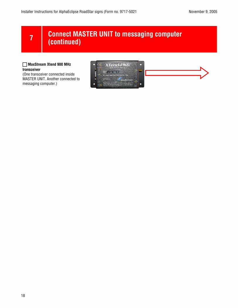
7 Connect MASTER UNIT to messaging computer (continued)
MaxStream Xtend 900 MHz transceiver (One transceiver connected inside MASTER UNIT. Another connected to messaging computer.)
18

November 9, 2005 Installer Instructions for AlphaEclipse RoadStar signs (Form no. 9717-5021
BLUE
Client transceiver (inside sign) Messaging computerrunning AlphaNET software
19

Installer Instructions for AlphaEclipse RoadStar signs (Form no. 9717-5021 November 9, 2005
BLUE
8 Temperature probe mounting
When properly installed, the temperature probe will indicate accurate temperature. The best location for the temperature probe is on the display or the display structure.
NOTE: Using the supplied 25-foot temperature probe cable (pn 7122-0401, 22 AWG), there is a maximum distance of 250 feet between the temperature probe and the sign. However, you can extend distance and potentially find a better mounting location by changing the cable gauge. Contact Technical Support for more information.
For two or more signs connected as Master/Secondary Master or Master/Slave, the temperature probe can be connected to either sign.
Do
• Choose a location with the following criteria:
– Air movement is not restricted by nearby walls or other obstructions. – The mounting background is light-colored and not dark-colored. – The location is above vegetation and not above asphalt or blacktop. – The location is on the north side of a building to provide protection from the sun.
• Shield the probe from the effect of the direct sun, reflected heat, or any nearby sources of heat, such as chimneys, lamps, vents, or HVAC ducts.
• If the temperature probe will be mounted to a heat-conducting surface, like metal, prevent the temperature probe’s case from conducting heat from this surface by placing a non-heat conducting material, like a wood board, between the surface and the probe.
• Mount the temperature probe at least 6 feet off the ground.
• Mount the temperature probe at least one foot below the eave of a protected overhang so convection currents (rising hot air flow) are not trapped around the temperature probe. Also, make sure convection currents are not blocked by the mounting plates.
• Mount the probe so that the vents face downward.
• Hand-tighten the mounting screws so as not to strip them.
Do not
• Mount the temperature probe along the top of the sign.
• Mount the temperature probe near sprinklers and water fountains.
Run the temperature probe cable and the sign’s power wires through the same conduit.
Installation
1. Mount the temperature probe with the vents pointing downward using the mounting holes OR the conduit holes on the bracket.
2. Run the temperature probe to the appropriate terminal block in the control cube.
NOTE: The temperature probe cable and the sign’s power wires must be run in different conduits.
20

November 9, 2005 Installer Instructions for AlphaEclipse RoadStar signs (Form no. 9717-5021
BLUE
3. Connect the temperature probe cable to the wireway terminal block as shown below.
Mount the temperature probe so that the vents point downward
Temperature probe
Wiring terminal block (on controller plate)
Mounting holes(circled)
Conduit holes
Run the temperature probe wire inside watertight conduit.
21
Installer Instructions for AlphaEclipse RoadStar signs (Form no. 9717-5021 November 9, 2005
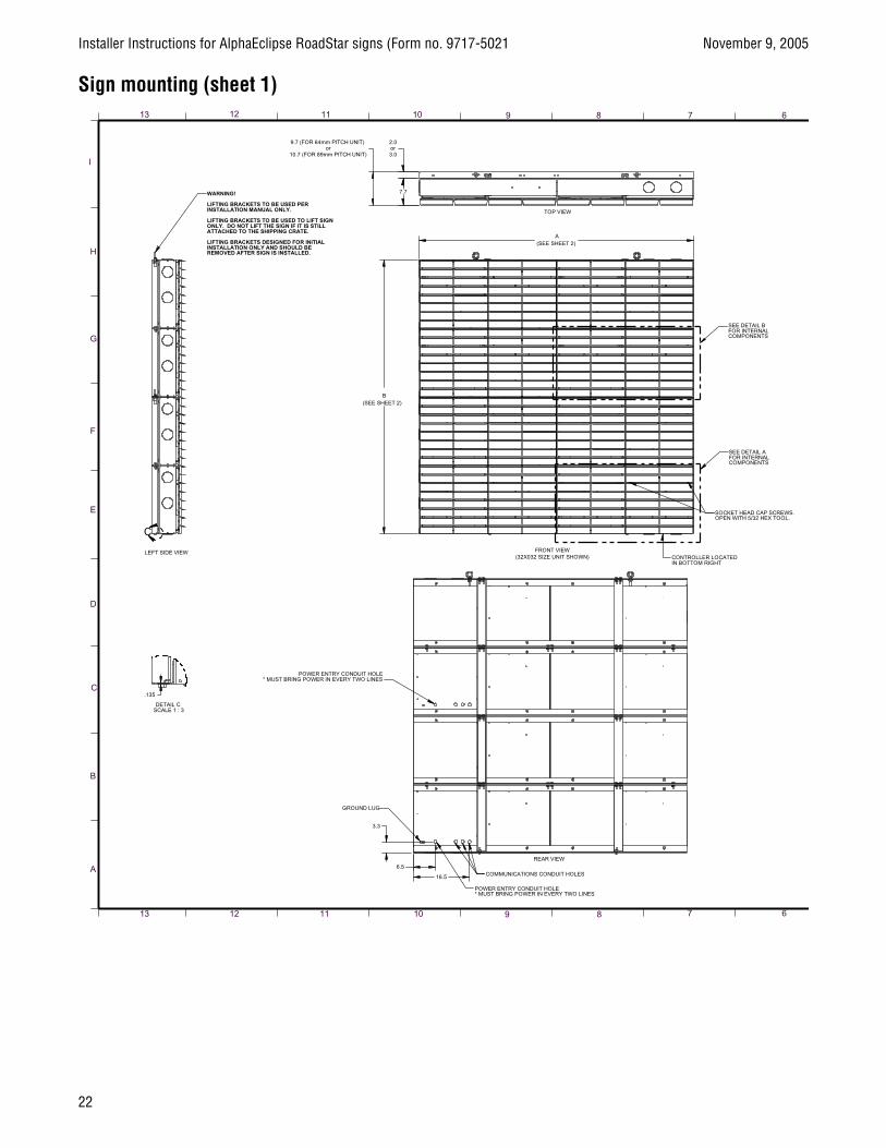
Sign mounting (sheet 1)
22

November 9, 2005 Installer Instructions for AlphaEclipse RoadStar signs (Form no. 9717-5021
23
Installer Instructions for AlphaEclipse RoadStar signs (Form no. 9717-5021 November 9, 2005
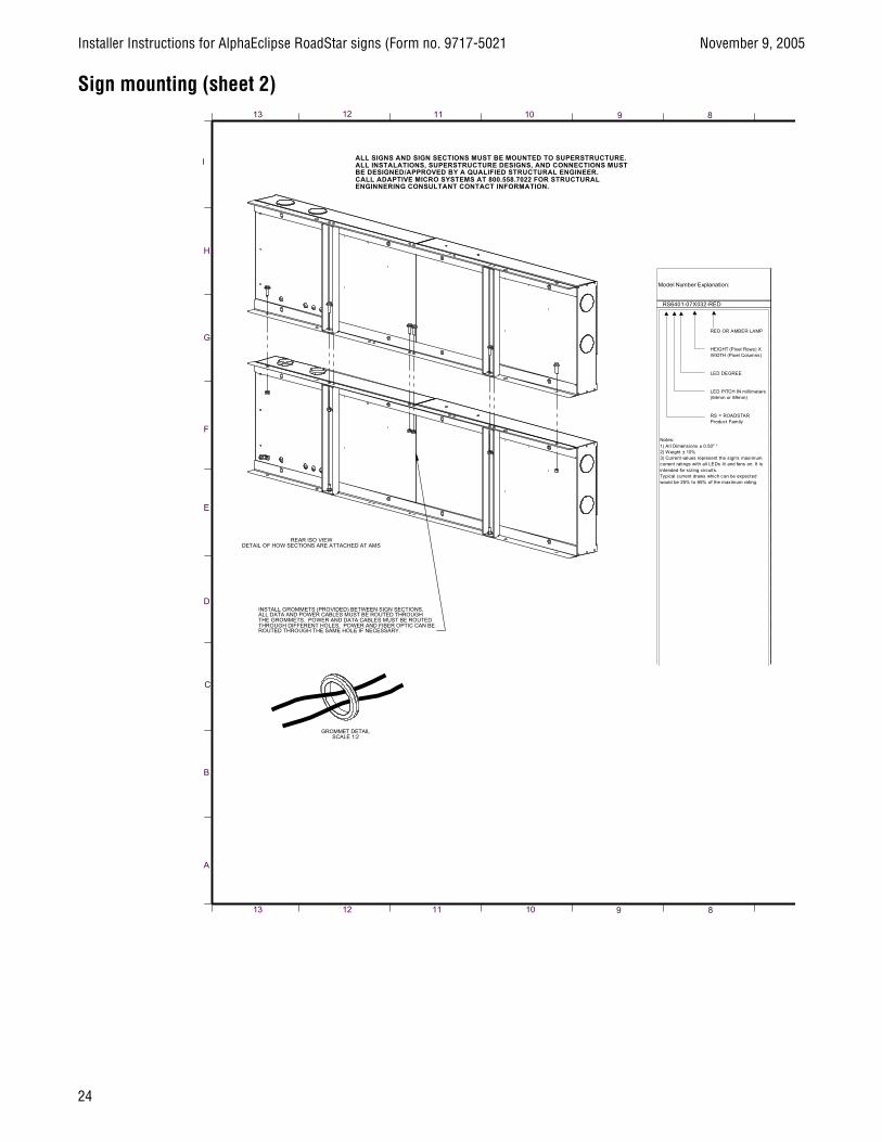
Sign mounting (sheet 2)
24

November 9, 2005 Installer Instructions for AlphaEclipse RoadStar signs (Form no. 9717-5021
25

Installer Instructions for AlphaEclipse RoadStar signs (Form no. 9717-5021 November 9, 2005
Sign mounting (sheet 3)
26

November 9, 2005 Installer Instructions for AlphaEclipse RoadStar signs (Form no. 9717-5021
27

Installer Instructions for AlphaEclipse RoadStar signs (Form no. 9717-5021 November 9, 2005
Sign mounting (sheet4)
28

November 9, 2005 Installer Instructions for AlphaEclipse RoadStar signs (Form no. 9717-5021
29

Installer Instructions for AlphaEclipse RoadStar Signs(Form number 9717-5021, November 9, 2005)
Instructions
for the
Sign Installer© Copyright 2005 Adaptive Micro Systems LLC. All rights reserved.Adaptive Micro Systems, 7840 North 86th Street, Milwaukee, WI 53224 USA 414-357-2020, 414-357-2029 (fax)http://www.adaptivedisplays.comTrademarked names appear throughout this document. Rather than list the names and entities that own the trademarks or insert a trademark symbol with each mention of the trademarked name, the publisher states that it is using names for
editorial purposes and to the benefit of the trademark owner with no intention of improperly using the trademark. The following are trademarks of Adaptive Micro Systems: Adaptive, Alpha, AlphaLert, AlphaNET, AlphaNet plus, AlphaEclipse, AlphaEclipse RoadStar, AlphaEclipse StreetSmart, AlphaPremiere, AlphaTicker, AlphaVision, AlphaVision InfoTracker, AlphaXpress, Automode, BetaBrite, BetaBrite Director, BetaBrite Messaging Software, Big Dot, Director, EZ KEY II, EZ95, PagerNET, PPD, PrintPak, Serial Clock, Smart Alec, Solar, TimeNet.
The distinctive trade dress of this product is a trademark claimed by Adaptive Micro Systems LLC. Due to continuing product innovation, specifications in this manual are subject to change without notice.