installed on clov by j-lay
TRANSCRIPT

High-performancepipelay see page 2
deepTechnology news from Subsea 7 - May 2014
seabed-to-surface
What’s inside...
03 Tethered Catenary Riser: a novel concept
04 Bundle technology: extending its capability
06 Integrity Management for Pipe-in-Pipe and Bundles
07 Innovative geotechnics: new mudmat design methodology
08 Welding for corrosion-resistant alloy pipelines
10 BuBi® Mechanically Lined pipe installed by reel-lay
12 Remote hydrocarbon sampling skid
16 Outstanding versatility: the Seven Arctic’s crane capabilities
Seven Borealis installing pipe on CLOV project, offshore Angola

Subsea technology: more important than everThe subsea industry is experiencing a continuous move into deeper water and towards more complex field developments. This trend brings a new set of challenges for subsea technology, including higher pressures, more difficult fluids, longer tie-backs and, increasingly, sea-bed processing.
These challenges are being met through innovative applied technology in many forms - heavier structures, longer umbilicals, more complex spoolpieces, more sophisticated risers and a great diversity of pioneering systems and equipment to be designed, qualified and installed.
At Subsea 7, we have always believed that applied technology plays a critical role in providing clients with effective solutions to meet the challenges of deepwater and harsh environments. As you will see in these pages, we have a long-established commitment to developing new technology which allows clients to realise their projects cost-effectively and efficiently.
We continue to invest in wide-ranging product portfolios in key technology areas such as riser design, welding and pipelay installation methods.
We collaborate with development partners on emerging game-changing technologies like pipeline health monitoring, high-performance thermally efficient Pipe-in-Pipe products, corrosion-resistant mechanically lined pipe and autonomous inspection vehicles.
We also continue to invest in the design and construction of the industry’s largest and most versatile fleet. We are, for example, currently building a new flagship heavy construction vessel, the Seven Arctic, which sets new standards in crane capacity and versatility, and will allow clients to execute large, complex projects more quickly and cost-effectively.
deep 7 profiles only a small number of the high-technology concepts that we have conceived, commercialised and are applying in client projects.
Don’t hesitate to contact us to explore any areas of mutual technological interest in more depth.
deep7 May 2014
02
Dr Stuart N Smith, Vice President Technology & Asset Development
John Mair, Technology Development Director
To meet the challenging flow assurance demands of an Angolan deepwater development in Total’s CLOV field, Subsea 7 recently designed a high-performance Pipe-in-Pipe (PIP) pipeline which is currently being installed by J-lay from its flagship pipelay/heavy-lift vessel, the Seven Borealis. The PIP installation is over 125km long and is being laid in 1400m of water. Subsea 7 also delivers similar high-performance PIP technology by using the reel-lay method.
The main challenges during this project were:
• achieving the required thermal performance • the laying tension in excess of 550t during the installation of the
PIP production lines• the large number of flowline structures • the stringent welding acceptance criteria for flowlines susceptible
to lateral buckling.
High-performance PIP
Subsea 7 collaborated on an advanced PIP design with development partner ITP InTerPipe using a 24m-long double joint which was fabricated onshore. The annulus in the double joint contains a blanket of IzoflexTM and the outer pipe is swaged down and welded to the inner pipe.
The annulus is then drawn down to a reduced pressure to achieve the required insulation properties. A further benefit offered by this design is that offshore welding activities can be confined to just the inner pipe. To complete the system, a sleeve is slid over the offshore weld and maintained with resin to ensure the continuity of the thermal and mechanical properties of the PIP. For the 12-inch by 16-inch PIP flowlines, a U value of 0.96 W/m2K was achieved, and for the 10-inch by 15-inch PIP flowlines a U Value of 0.76 W/m2K was achieved.
Installation characteristics
• Safe and efficient field joint coating operations were required, building effective cooperation between sub-contractors, project and offshore resources teams. This high level of collaboration was essential to ensure the efficient integration of the equipment required to manage the handling of heavy PIP sleeves, and the injection of large amounts of resin.
• Increased pipe diameters were used, with 12-inch inner pipes inserted in 16-inch outer pipes. This called for laying tension in excess of 550t.
• A series of studies and tests was necessary to verify the pipeline integrity during the laying operation. These included assessment of the friction coefficient between the pipe and clamp, and of the mechanical resistance to the squeeze load.
• Specific methods were developed for the abandonment of the heavy catenaries, using all the available installation equipment on board the Seven Borealis.
Multiple in-line structures
One characteristic of the CLOV field layout is the large number of flowlines of relatively short length, and the large number of in-line structures. In total, 52 structures, including ten in-line, were installed and welded to the flowlines. The combination of the Seven
Hervé Quintin, CLOV Engineering Manager
High-Performance Pipe-in-Pipe installed on CLOV by J-lay

High-Performance Pipe-in-Pipe installed on CLOV by J-lay
seabed-to-surface
03
For further information contact [email protected]
Installation of PLET on board the Seven Borealis on CLOV project, offshore Angola
Borealis and the J-lay installation method proved particularly well suited to this type of work. Structures were installed using the PLET Handling System, which permitted an early and safe fit-up operation. Special double joints of different lengths were prepared in advance in order to adjust the final length of the line. Structures were all installed well within the pre-defined target box, and tie-in spool dimensions were maintained close to their nominal dimensions.
Fatigue performance
In general, fatigue performance and associated welding acceptance criteria are not critical for flowlines. However, certain sections of the CLOV flowlines were susceptible to significant cyclic displacements and the associated high levels of fatigue induced by the operating conditions.
For these critical locations, more stringent welding acceptance criteria were adopted and special sections were welded with allowable defect sizes at the limit for detection by Automatic Ultrasonic Testing (AUT). The flexibility offered by the J-lay method ensured that these could be installed in the correct locations, thus limiting the number of special joints required.
The successful project execution on CLOV is confirmation that Subsea 7 possesses the technology, assets, and project teams capable of meeting the most demanding challenges of complex deepwater projects.
Tethered Catenary Riser: a novel concept for ultra-deep water
Tethered Catenary Riser (TCR)
Jean-Luc Legras, Chief Engineer - Design Authority
Subsea 7 has added a further new riser concept to its portfolio for field development in deep and ultra-deep waters: the Tethered Catenary Riser (TCR). The TCR concept has been under development since 2010, and consists of a number of Steel Catenary Risers (SCRs) supported by a subsurface buoy which is tethered to the seabed by a single pipe tendon and anchored by a suction pile. Flexible jumpers are used to make the connection between the Floating Production Unit (FPU) and the buoy. Umbilicals run without interruption from the FPU to their subsea end and are supported by the buoy.
The system has all the advantages of decoupled riser arrangements. Flexible jumpers effectively absorb platform motions, and therefore the rigid risers and tendons have very limited dynamic excitation. The system can be installed before the FPU arrives on site, which reduces the time before first oil. The riser system is designed for optimal operations with between four and eight risers, in addition to a number of umbilicals, and is therefore best suited to supporting one or two drilling centres.
This development work clearly indicates that it is possible to have a robust design using presently qualified materials and technology. The components included in the TCR are all field-proven and are commonly used in existing riser systems.
An installation method very similar to the one commonly used by Subsea 7 for Single Hybrid Risers (SHRs) has been selected for the buoy and tether system.
The TCR is therefore a credible new option for use in deepwater developments anywhere in the world.

04
deep7 May 2014
Extending Bundle technologySubsea 7 has designed, fabricated, and installed Bundles (towed pipeline production systems) for over 33 years, with 69 Bundles installed to date.
In recent years, Bundles have been accepted as a technically and commercially attractive solution that allows difficult fields to be successfully developed.
Bundle technology presents significant potential for extending existing facilities or opening up new developments, and its global future and prospects for further innovation are equally exciting.
The challenges of deeper water
Deeper water is a challenge for Bundle design, since it places considerable demands on the collapse resistance of the carrier pipe and the internal nitrogen pressures. The greatest water depth for a Subsea 7 Bundle design to date is 410m, for BG’s Knarr development in Norway, but it is expected that this can be extended in the future by use of alternative buoyancy arrangements.
Pipeline Bundles are currently limited to a maximum length of 7.6km, the length of Subsea 7’s Bundles fabrication line at Wick, in the North of Scotland. For longer tie-back distances, multiple Bundles connected in series can be produced, such as BP’s Andrew project in the North Sea, which used four Bundles, extending a total distance of 27.8km.
Health monitoring
Subsea 7 has recently developed pipeline health monitoring systems for use in individual Pipe-in-Pipe flowlines using fibre-optic technology. Advances in fibre-optic technology present unique features that significantly outperform conventional sensing techniques. The ability to measure temperatures and strain at thousands of points along a single fibre is a particularly productive area of investigation. In the past few years, innovative distributed strain and temperature monitoring
Martin Goodlad, Bundle Design Manager
Knarr Bundle before carrier tie-in
techniques using optical fibres have demonstrated their efficiency in providing monitoring data along a single optical fibre cable.
The application of this technology will allow real-time monitoring of corrosion, erosion, blockages and leaks, and in the process will enhance Subsea 7’s Life-of-Field capabilities. This new technology also complements our recent developments in Electrically Heat Traced Flowline (EHTF) technology.
How hot can a Bundle get?
Pipeline Bundles are currently ideally suited to development of HP/HT fields, and in many cases have allowed the development of fields where no other technology provided a practical or financially viable solution.
The design and fabrication method for Bundles allows the internal bundle components to expand differentially and therefore relax the axial forces experienced by the flowlines. The reduction in axial force can be up to 17% in some cases.
This allows the Bundle flowlines to be designed using stress-based criteria. A study is currently being undertaken to examine the opportunities for expanding the current design limits to beyond 160˚C and 604 bar, and will review the impact on all Bundle components.
Flowline pre-tensioning is one potential enhancement. During the Bundle fabrication, tension is locked into the high-temperature flowlines, thereby reducing the compressive forces experienced during operation.
Subsea 7 has also recently developed welding procedures for X80 pipelines. Lower weld criteria can be accepted for Bundles than with reeled flowlines. Flowlines are not plastically deformed during the reeling process and therefore do not not require weld over-matching.

05
seabed-to-surface
Investment in the futureIn early autumn 2013, Subsea 7 invested over $8.8million (£5.5m) in refurbishing its pipeline Bundle fabrication site at Wick, in the North of Scotland. The refurbishment programme is to be carried out in two phases and includes new state-of-the-art equipment for five firing lines, a 230m extension to the main fabrication shop and a new office and welfare complex at the landward end of the facility. Refurbishment is scheduled for completion in 2014.
Bundles – a story of ongoing developmentBundle technology is based on a core of standard system design methods which have been steadily developed over 30 years. Subsea 7’s Bundle systems offer a number of advantages over conventional flowlines, in particular where multi-flowlines and high thermal performance are important. The main benefits and advantages of next-generation Bundle systems include excellent thermal performance to prevent wax formation and hydrates, prevention of global buckling for HP/HT fields, multiple bundled flowlines, ,mechanical and corrosion protection, and the potential for re-use.
For further information contact [email protected]
The largest Bundle carrier pipe diameter specified for a project is currently 56.4-inches, for Total’s West Franklin North Sea development (installed in 2013). The launchway at Subsea 7’s Wick fabrication yard is currently expected to accommodate carrier pipes up to 60-inches in size. The heaviest towhead weight to date to be launched is 525t, but this is expected to be exceeded by the Norwegian BG Knarr project towhead which will weigh around 590t. To further expand the Wick site capabilities, a second launchway will be installed with capacity for up to 700t towheads.
Case study - Bundles for the Barents Subsea 7 recently completed a study for Statoil exploring the use of Bundles in the Barents Sea. The study primarily focused on the fatigue implications on the carrier pipe which may be caused by extended tow lengths in excess of 2,000km.
This important study involved detailed analysis of different tow configurations and depths in order to limit fatigue damage. The analysis drawn from this study was complex and challenged by changes in the typical wave spectral data as the tow headed north, and as the spectra altered, from spectral characteristics typical of the North Sea, to the Arctic Ocean and the Barents Sea.
The study demonstrated that towing Bundles up to 2,000km is a realistic prospect, and the extended tow duration was accepted by the client. The study also considered laying the Bundle on the seabed over multiple iceberg scars. The study demonstrated that the deployment of Bundles reduced the amount of rock dump required when compared to conventional pipelay due to the enhanced free-spanning capabilities of the Bundle.
Current Bundle development initiatives will help to ensure the future of this important technology.
Super duplex production line in Wick, North of Scotland

The profile of Integrity Management within the global oil and gas industry is higher than it has ever been, in particular when operating in deep water and difficult or pioneering offshore environments. The aim of Integrity Management is to ensure that facilities remain fit for purpose, and that any remedial action can be taken in good time.
Integrity Management is reliant on information for a given piece of equipment or system being collected and analysed. Periodic inspection, as part of Inspection, Repair and Maintenance (IRM) campaigns, can provide data about the asset at a precise point in time during an inspection. Thereafter, specialist and predictive analyses are required to assure continued safe use until the next scheduled inspection is due.
06
deep7 May 2014
Dr Gordon Drummond, Technology Manager
For further information contact [email protected]
Continuous Integrity Management:subsea Pipe-in-Pipe and pipeline Bundles
Pipeline freespan detected by change in strain
Pipeline buckle detected by change in strain
To date, Subsea 7 has determined how to include fibre-optics within the system design and manufacture of the overall assembly. The company has proved that it can integrate the fibre elements and have them successfully installed by the pipeline reeling process. The sensitivity of the measuring device to detect and monitor pipeline deterioration has been demonstrated.
The next stage of the project involves developing algorithms which will trigger alarms when certain thresholds are exceeded. Thereafter, it becomes a relatively straightforward process, with the point of strain in a pipeline identified and monitored until it becomes critical and a threat to integrity.
Subsea 7 is ready to bring to the market a continuous monitoring solution which offers the ability to enhance operational performance, while providing ongoing awareness of the health of PIP and Bundle systems.
Subsea 7 now offers an independent risk-based Integrity Management service that supports operators of subsea assets in maintaining their facilities in an optimum condition. A strong understanding of clients’ integrity requirements allows Subsea 7 to include integrity management considerations in designs at an early stage and assess the output from various measuring devices to demonstrate the state of health of pipeline systems.
The maturity of sensory technology now allows parameters to be continuously measured and, from that, the health or well-being of the asset can be determined. This is common practice in other industries; examples include particle monitoring, which provides intelligence on wear in helicopter gearboxes, or displays of car tyre pressures on modern dashboard displays. Subsea 7 is looking to import and adopt technologies that are qualified and proven in other industries.
Significant steps have been taken to develop real-time monitoring for higher-end products, specifically Pipe-in-Pipe (PIP) and pipeline Bundles. The most prevalent form of degradation of subsea hydrocarbon pipeline systems is internal corrosion and a consequent loss of containment, which drives the requirement to verify integrity and safe operation.
Subsea 7 has engaged in a systematic programme of investigation to define the primary threats to which subsea pipelines are exposed, and investigate the nature of any degradation. Calibrated with data drawn from this study, sensory devices were then deployed to detect potential threats. Fibre-optic sensors were chosen as the preferred means to detect and measure deterioration.
Pipeline hydrate obstruction detected by change in strain

07
seabed-to-surface
For further information contact [email protected]
Sliding mudmats
Current mudmat design scenarios for PLETs are often aimed at preventing sliding away from the foundation. However, controlled sliding of the mudmat on the seabed can be beneficial since axial loads in the pipeline and jumper can relax. A design guideline that did not previously exist in the industry has been developed by Subsea 7 through another pioneering research programme, in collaboration with Cathie & Associates, geotechnical engineering consultants. This design guideline is now being validated through comprehensive model tests in a geotechnical centrifuge at IFSTTAR, a leading research institute in France.
Working at the leading edge of innovation in offshore geotechnicsIn today’s offshore environment, where exploration and recovery of hydrocarbons are at increasingly greater water depths, shallow-skirted foundations, generally referred to as ‘mudmats’, are used extensively for subsea structures. These include well manifolds, pipeline end terminations (PLETs) or in-line structures, many of which need to be designed to withstand fully three-dimensional loading due to contraction and expansion of the connecting pipelines and jumpers.
The mudmats are typically rectangular in plan, and fitted with peripheral and internal skirts to increase their stability for the soft soil conditions commonly encountered in deep water (with the strength of only a few kPa). It has become critically important to maintain a regime of continual improvement to mudmat design, primarily to keep sizes within a range that can be easily installed by pipelay vessels.
Hybrid foundations
A novel approach to reducing the plan area of mudmats involves incorporating pin-piles at each corner of the mudmats, resulting in a hybrid foundation where the load is shared between mudmat and piles. The piles offer a significant increase in capacity, particularly in respect to the sliding and torsional modes of failure.
Régis Wallerand, COE Geotechnics
Field development showing a number ofstructures with mudmats
Skirted mudmats
Subsea 7’s geotechnical engineers continue to lead highly innovative programmes in the ongoing development of mudmats, some of which have already brought great benefits to SURF projects like the CLOV deepwater development for Total in Angola. This was made possible through the development of a new design methodology in collaboration with the University of Western Australia (UWA), aimed at optimising the size of fixed skirted mudmats for subsea structures. Significant improvements in the design, fabrication and installation of subsea structures are a result of this programme.
PLET with skirted mudmats on the Seven Borealis
Scale model tests in a centrifuge
Validation of the potential of such hybrid foundations was provided through a research collaboration between Subsea 7, BP and the UWA. This innovative foundation system is being adopted on Esso’s Erha North project offshore Nigeria as a cost-effective mitigation solution against pipeline ‘walking’.
Leading-edge
These three research programmes on deepwater shallow foundations have kept Subsea 7 at the leading edge of innovation in offshore foundations, producing cost-effective and reliable solutions for clients.
Hybridfoundation
concept

08
deep7 May 2014
Stainless steels are increasingly being used for oil and gas pipeline applications. The last two decades have seen the development of specific designs of stainless steel grades, including low-carbon 13Cr martensitic and duplex stainless steels which offer improved properties and cost effectiveness for a wide range of operational service environments. The selection of the optimum stainless steel grade requires careful consideration of the service environment. Additionally, the successful utilisation of such pipeline materials requires critical control of the welding procedures if the required corrosion performance is to be maintained.
The current generation of weldable 13Cr martensitic stainless steels is a cost-effective choice for CO2 and mildly sour environments. These steels offer high strength at elevated temperatures that allow material and fabrication savings to be made through reductions in pipe wall thickness. Such stainless steels exhibit relatively high hardenability, so that hydrogen-controlled welding procedures are necessary to mitigate the risk of fabrication cracking. Typically super-duplex stainless steel filler wires (25%Cr) in de-hydrogenated form are used for welding in order to achieve matching weld metal strength properties. It is also generally accepted that a short post-welding heat treatment (typically 650°C for five minutes) has a beneficial effect on heat-affected zone (HAZ) hardness and stress corrosion cracking resistance.
Recently Subsea 7 has developed improved welding technology for welding 13Cr steels. This has involved the use of the Cold Metal Transfer (CMT) process to deposit good-quality root passes in a combination with the Pulsed Gas Metal Arc Welding (PGMAW) process for deposition of high-quality fill and cap passes. The CMT process is an advanced short-circuit metal transfer GMAW technique which enables the root pass to be welded without the need for an internal copper shoe. This has resulted in a significant improvement in corrosion performance. This improved welding solution was successfully deployed for Statoil’s Svalin project in Norway
For further information [email protected]
Manual GTAW welder qualification for duplex stainless steel bundle project
Welding developments for corrosion-resistant pipelinesRichard Jones, Pipeline Production Group Welding Technology Manager
Mechanised CMT welding of clad pipe
which involved the fabrication of 5.8km of production flowline in 283.9mm ID x 20mm WT SMLS 13Cr – 2.5Mo SPD line pipe.
The duplex stainless steel alloys offer improved corrosion resistance and resistance to chloride stress corrosion cracking while also maintaining high strength properties. This is especially the case for the more highly alloyed super-duplex grades (25%Cr) which offer remarkable corrosion resistance and high strength. The properties of the duplex stainless steels are highly dependent on the microstructural phase balance. Generally speaking, phase balance is considered to be optimised when ferrite and austenite are in roughly equal critical proportions. This is dependent on the thermal history.
Therefore, during pipeline fabrication, careful control of the preheat/interpass temperature and heat input is necessary to ensure that the optimum phase balance is maintained in the weld metal and HAZ. Subsea 7’s CMT/PGMAW welding technology can be used to advantage for the welding of duplex steels. Precise control of the weld root profiles and heat input for welding ensures that the optimum combination of strength, toughness and corrosion performance is maintained.
This technology will be deployed for Noble Energy’s West African Diega Pipe-in-Pipe (PIP) project which will involve fabrication of 14km inner pipe comprising 25% Cr super-duplex stainless steel of nominal dimension 219.1mm OD x 13.7mm WT. Fabrication is due to commence mid-2015 in Subsea 7’s Port Isabel spoolbase in the USA.

09
seabed-to-surface
The AIV is designed to dive to 3,000m.
Because of its unique basket deployment system, all of the AIV’s power resources can be dedicated to the inspection missions, with no power wasted on a dive and recovery process. Missions of up to a single day can be achieved at a speed of two knots, depending on the currents experienced.
There is a comprehensive topside control system that plugs into the AIV on deck. Complex missions can be programmed through the control system, undertaking the same full inspection sequencing deployed by a WROV. The deck control system can undertake system diagnostics. All of these activities can be managed by onshore control centres, with the only reliance on another platform being a plug-in to the deck cable.
De-risking of the autonomous nature of the system includes building numerous control behaviours to account for any system anomalies or emergency situations. The vehicle is programmed to return to its basket if the AIV believes there are any anomalies that will compromise the mission.
In an emergency situation, depending on the deployment mode, the vehicle will either sink to the seabed or release buoyancy and float to the surface, signalling for recovery.
Autonomous Inspection Vehicle (AIV) – a game-changing technology
Subsea 7’s Autonomous Inspection Vehicle (AIV) was conceived as a pioneering deepwater autonomous inspection capability. In its current development stage and configuration, it is a visual inspection vehicle which will augment the company’s workclass Remotely Operated Vehicle (WROV) and observation class Remotely Operated Vehicle (ObsROV) inspection services.
The revolutionary and unique aspect of the Subsea 7 AIV is its ability to hover and safely achieve close approach and detailed inspections of subsea equipment.
The AIV has a dedicated launch and recovery system and winch, and is deployed from its own basket station on the ocean floor. It can be deployed from a vessel and work in tandem with a WROV carrying out Inspection, Repair and Maintenance (IRM) tasks, or permanently based on a Floating Production Storage and Offloading (FPSO) installation. No surface mother vessel needs to follow the vehicle.
The system will be maintained and operated by a small crew of dedicated technicians. The data processing takes place onshore with a design that allows the support team to undertake its work in near real time.
The AIV system is currently configured with video, which is soon to be upgraded to HD video cameras and 3-D high-resolution sonar. The battery life and data storage permits up to 24-hour missions, collecting continuous data through its sensors. For further information contact
Hugh Ferguson, Projects and Operations Director, Life-of-Field

10
deep7 May 2014
With corrosive fluids posing an increasing challenge for field developments and corrosion-resistant alloy (CRA) materials becoming more expensive, Subsea 7 has been conducting an extensive testing and development programme since 2010 to qualify the installation of the cost-effective mechanically lined BuBi® pipe by reel-lay. A DNV certificate of Fitness for Service and two significant supply and install projects have been awarded to Subsea 7 during this period. Further development work has demonstrated the suitability of the product for fatigue-sensitive applications, such as Steel Catenary Risers (SCRs).
The main challenge associated with the installation of BuBi® lined pipe by reeling was to demonstrate that the inner pipe, or liner, did not suffer from
local buckling during the spooling process. Equally important was to demonstrate the integrity of the weld joining the liner pipe to the outer pipe at the ends of each joint, or seal weld.
Grégory Toguyeni, Senior Welding and Materials Engineer
A total of 17 test strings has been tested, using carbon steel grade X65 for the outer pipe and 316L stainless steel, alloy 825 and alloy 625 for the liner.
The test strings were made up of BuBi® pipe sections welded together using the mechanised Hot Wire Pulsed Gas Tungsten Arc Welding (PGTAW) process with alloy 625 filler metal. Since then, a procedure based on Pulsed Gas Metal Arc Welding (PGMAW) has also been qualified for improved productivity.
A detailed laser metrology examination and mapping of the full internal surface of the pipe at manufacturing stage and before and after reeling simulation was also carried out. This innovative technique permitted detailed monitoring of the behaviour of the liner pipe surface throughout the reeling
A cost-effective solution:transporting corrosive fluids using BuBi® lined pipe and reel-lay installation techniques
Full-length mapping of internal liner surface using laser equipment
S-N curves showing BuBi® pipe fatigue life up toDNV class C target curve and failure at class B1
* Installation methodology includes licence from Statoil Petroleum A.S.
11
seabed-to-surface
For further information contact [email protected]
process down to an accuracy of 50μm on any surface feature. This allowed both Subsea 7 and pipe manufacturer BUTTING to understand the relation between pre-existing surface features on the outer pipe ID and the value of the gripping force obtained through BUTTING’s ‘push-out test’.
All test pipes were subjected to a conservative cyclic bending test, or reeling simulation, using a radius of curvature of 7.5m. This allowed testing of the specific Subsea 7 reeling technique using low internal pressurisation of the pipe.*
Full-scale resonance fatigue testing of several pipes was conducted in accordance with DNV-RP-C203 at The Welding Institute in Cambridge. Four progressively higher fatigue classes were selected for the test. Specimens were fully inspected after reaching each fatigue class in order to confirm the absence of any failure initiation not only on the carbon steel outer pipe, but also on the corrosion-resistant liner and at the seal welds. The endurance of the pipe and its welds was thus confirmed to exceed the target level of DNV fatigue class C (DNV-RP-C203). The test was continued until failure in order to understand the ultimate resistance, the failure mode and location. Failure occurred at DNV (Class B1). A good understanding of the product capability was gained from the subsequent failure investigation, such as in the carbon steel pipe and liner, and failure initiation point.
Scanning Electron Microscope (SEM) image of an austenitic liner material fracture face; fatigue striations can be observed and allow calculation of fatigue crack growth rate
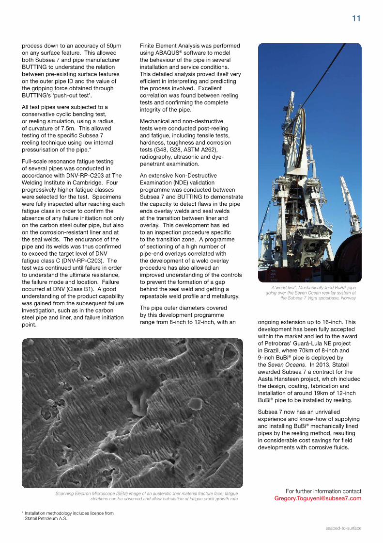
A‘world first’. Mechanically lined BuBi® pipe going over the Seven Ocean reel-lay system at
the Subsea 7 Vigra spoolbase, Norway
Finite Element Analysis was performed using ABAQUS® software to model the behaviour of the pipe in several installation and service conditions. This detailed analysis proved itself very efficient in interpreting and predicting the process involved. Excellent correlation was found between reeling tests and confirming the complete integrity of the pipe.
Mechanical and non-destructive tests were conducted post-reeling and fatigue, including tensile tests, hardness, toughness and corrosion tests (G48, G28, ASTM A262), radiography, ultrasonic and dye-penetrant examination.
An extensive Non-Destructive Examination (NDE) validation programme was conducted between Subsea 7 and BUTTING to demonstrate the capacity to detect flaws in the pipe ends overlay welds and seal welds at the transition between liner and overlay. This development has led to an inspection procedure specific to the transition zone. A programme of sectioning of a high number of pipe-end overlays correlated with the development of a weld overlay procedure has also allowed an improved understanding of the controls to prevent the formation of a gap behind the seal weld and getting a repeatable weld profile and metallurgy.
The pipe outer diameters covered by this development programme range from 8-inch to 12-inch, with an ongoing extension up to 16-inch. This
development has been fully accepted within the market and led to the award of Petrobras’ Guará-Lula NE project in Brazil, where 70km of 8-inch and 9-inch BuBi® pipe is deployed by the Seven Oceans. In 2013, Statoil awarded Subsea 7 a contract for the Aasta Hansteen project, which included the design, coating, fabrication and installation of around 19km of 12-inch BuBi® pipe to be installed by reeling.
Subsea 7 now has an unrivalled experience and know-how of supplying and installing BuBi® mechanically lined pipes by the reeling method, resulting in considerable cost savings for field developments with corrosive fluids.

deep7 May 2014
12
As the need to exploit offshore oil and gas deposits in increasingly challenging environments increases, the economic development and safe operation of technologies has become more critical.
The requirement to sample and establish the characteristics of produced well fluids has been long established in order to provide:
• fluid composition and flow data for each well
• reservoir management
• fiscal allocation.
Traditional methods for sampling and testing wells employed the use of a dedicated subsea test header, pipeline or riser, connected to test separators and individual single-phase flow meters located on a surface production facility. But, as production has moved into deeper water, Multi-Phase Flow Meters (MPFMs) have been introduced to monitor or meter individual well production prior to a manifold combining the production from several wells for onwards transport in a single riser or flowline.
Since reservoir and well fluid characteristics alter during their lifecycle, it is essential that MPFMs are recalibrated to account for these changes to ensure their continued accuracy. To enable recalibration to be performed, regular periodic samples of the well production fluids are taken. The samples are extracted from the flowing production fluid in close proximity to the MPFM. The samples are tested to provide up to-date fluid data to permit recalibration of the MPFM to maintain operations at optimum accuracy.
It is critical that an accurate and representative sample can be taken to ensure precise calibration of the MPFM and its continued effectiveness over time. It was at this point that the concept of a sampling skid attached to an ROV was first developed. This provides the critically accurate
Remote hydrocarbon sampling skid
methodology and can be deployed to meet the client’s schedule and mitigate any timescale implications.
The origins of the remote hydrocarbon sampling skid
A patent was granted for Subsea 7’s first remote hydrocarbon sampling skid in 1998 and revised again in 2010. This early sampling system covered relatively shallow water installations and was not required to mitigate for hydrate or waxing issues. Obtaining samples relied upon well pressure to fill the sample bottles as this was greater than the ambient seawater at the sample location. The requirement to protect the environment from hydrocarbon release was paramount with this design.
The sampling skid in operation today is capable of taking separate samples from up to eight individual wells in a single dive. During operation and recovery, the temperature and pressure of the samples are maintained to prevent the sample coming out of phase and to prevent hydrates forming in the sample or skid pipework. On recovery, the sample bottles are removed from the skid and transported ashore for analysis to allow calibration of MPFMs, and for fiscal allocations to be determined.
Mick Fowkes, Applications Development Manager
Sampling skid being deployed
Control system overview
Communications between the sampling skid and a topside laptop PC is by means of the host ROV fibre-optic multiplexer, over an RS232 link. A minimum of one spare serial channel is required to interface the skid and all relevant sensor data telemetry from the surface to the ROV electronics pod. Connection from the sampling skid electronics control systems to the ROV electronics pod is via copper cables.
A single 115Vac @ 7A power supply from the host ROV provides the sampling skid with all necessary power.
Control panel
Electrical power is supplied from the host ROV to the skid-mounted control system equipment, which comprises two 12-station valve packs, various cameras and sensors, and a Pressure Transducer Module (PTM).

For further information contact [email protected]
seabed-to-surface
13
Topside equipment overview
Once all hydrocarbons and slops have been re-injected into the SU, which is followed by a MEG flush, only small amounts of sample hydrocarbons are recovered at the surface following the test campaign.
In the event of a dead-sub or vessel blackout when the ROV has to be recovered mid-process, the hydrocarbons are recovered at the
There are six video cameras on the sampling skid. Three cameras are powered and interfaced directly from the ROV. All pictures from these cameras are available at the topside ROV control console. Three cameras are powered and interfaced from the valve packs on the skid and only one of these pictures will be available for topside transmission at a time. Video switching allows for each of these video streams to be monitored.
Subsea hardware requirements
In order to perform sampling without interrupting production, a Sampling Unit (SU) is required to be incorporated in the design of subsea infrastructure.
The SU is a mixing device which separates the gas phase from the liquid phase to ensure a liquid sample volume. In the mixer, the gas flows upwards whereas the liquid phases are mixed towards the bottom. The SU can be installed upstream of the Multiphase Flowmeter (MPFM) in a topside installation or subsea in a manifold, tree or a flowline jumper.
Sampling ports at the lower and upper part of the SU chamber are piped to an ROV hot-stab receptacle mounted on the unit. Double block valves provide isolation between the chamber and hot stab.
Sampling skid design overview
The hydrocarbon sampling skid is mounted under the delivery ROV and has a similar footprint. The skid houses the following subsystems:
• Eight US Department of Transport-approved sample bottles, pipework and isolation valves, housed in a heated water jacket, manufactured from buoyancy materials
• Heating system
• Syringe-style suction pump with the ability to extract process fluids and gas from the SU that is of a lower pressure than the ambient seawater at the work site.
• Syringe-style monoethylene glycol (MEG) injection pump system
• Syringe-style slops suction and reinjection pump system
• Slops storage flask
• Buoyancy
• Sampling tool
• Double-block isolation valve tool
• Failsafe system
Sample bottles
Valve packs
Water jacket
Double block valve interface tool
Interface stab
surface and then flushed out from the skid into the topside equipment slops tank.
The topside equipment is mounted in a fabricated basket and consists of a flushing solvent tank and slops container, complete with nitrogen cap. Venting of the slops tank is provided to accommodate extreme deck temperatures.
System flushing unit, slops and solvent tanks
Skid storage and spares container
Topside equipment overview
Illustration of Sampling Skid
Fleet development update
The Seven Waves heads for BrazilFor many years Subsea 7 has provided a number of vessels for Petrobras, the Brazilian national energy company, supporting contracts installing many kilometres of flexible pipe. With the opening up and development of deepwater pre-salt Brazilian fields, Petrobras now has a requirement for a number of new-generation, high top-tension flexible pipe installation vessels.
Based on Subsea 7’s extensive field experience in Brazil and its management of cost-effective shipbuilding, Subsea 7 has won contracts from Petrobras requiring the construction of four specialist flexible pipelay vessels. The first of these, the Seven Waves, has now been completed and transited for Brazil in March 2014 to commence operations ahead of schedule. The Seven Waves was built in the Netherlands by IHC Merwede, with the main 550t vertical tiltable lay tower (TLS) installed by Huisman.
deep7 May 2014
14
The subsea industry is experiencing a continuous move into deeper waters and towards more complex field developments. New challenges faced include higher pressures, more difficult fluids, longer tiebacks and, increasingly, seabed processing. These developments require heavier structures, longer umbilicals, more complex spoolpieces and a greater diversity of equipment to be installed. This in turn leads to a demand for larger, more versatile vessels with higher capabilities which can execute projects more quickly and cost-effectively.
Subsea 7 has recently confirmed the specifications for its new Heavy Construction Vessel (HCV), to be named the Seven Arctic, which is being built in South Korea for delivery in 2016.
The new HCV will be equipped with a 325t top tension Huisman Vertical Pipelay System, a 7,000t MAATS underdeck basket for storage of flexible pipe/umbilicals and an innovative new design, a 900t Huisman rope-luffing knuckle-boom crane (see back page for more details).
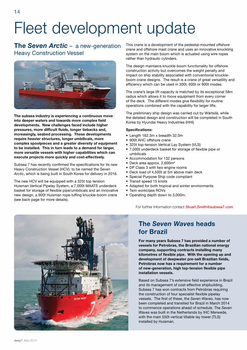
The Seven Arctic – a new-generation Heavy Construction Vessel
This crane is a development of the pedestal-mounted offshore crane and offshore mast crane and uses an innovative knuckling system on the main boom which is actuated using wire ropes rather than hydraulic cylinders.
The design maintains knuckle-boom functionality for offshore construction activity but overcomes the weight penalty and impact on ship stability associated with conventional knuckle-boom crane designs. The result is a crane of great versatility and efficiency which can be used in 300t, 600t or 900t modes.
The crane’s large lift capacity is matched by its exceptional 58m radius which allows it to move equipment from every corner of the deck. The different modes give flexibility for routine operations combined with the capability for larger lifts.
The preliminary ship design was carried out by Wärtsilä, while the detailed design and construction will be completed in South Korea by Hyundai Heavy Industries (HHI)
Specifications:
• Length 162.3m x breadth 32.0m• 900t AHC offshore crane• 325t top-tension Vertical Lay System (VLS)• 7,000t underdeck basket for storage of flexible pipe or
umbilicals• Accommodation for 132 persons• Deck area approx. 2,600m²• DP Class 3 with two engine rooms• Deck load of 4,500t at 5m above main deck• Special Purpose Ship code compliant• Transit speed 15 knots• Adapted for both tropical and winter environments• Twin workclass ROVs• Operating depth down to 3,000m.
For further information contact [email protected]

The Seven Kestrel – a new high-performance DSV
For further information contact [email protected]
For further information contact [email protected]
seabed-to-surface
15
depth of 300m. The chamber complex consists of four living chambers, four wet units, and two Transfer Under Pressure (TUP) chambers. The gas storage capacity is 27,000m2 below deck and the vessel also has deck oxygen and therapeutic gas storage facilities.
The dive system environment is operated and controlled by a purpose-designed, semi-automatic control system, which also has an independent back-up manual system in place.
The launch and recovery system (LARS) for the diving bells consists of two independent systems, each comprising three electrically driven wire winches and one electrically driven umbilical winch. The systems each contain passive heave-compensation capabilities.
A single moonpool-deployed observation ROV will also be installed to support diving operations.
DimensionsLength overall 145.9mBreadth moulded 29.9mDepth to main deck 13.0m
Deck CranesHuisman mast craneMain line (AHC) 400t @ 16.5mMaximum reach 39.5mWire length 2,500mWhip line (man riding) 40t @ 58mMaximum reach 58mWire length 500mCargotec auxiliary knuckle-boom craneMain line (AHC) 25t @ 15mMaximum reach 32mWire length 2,800mWhip line (man riding) 10tMaximum reach 33mWire length 150mHS Marine Service Crane on the TLS towerMain line (man riding) 25t @ 10mMax reach 15m
18-man chamber complex with two diving bells connectedto the Transfer Under Pressure (TUP) chambers
2 x TTS stores / moonpool handling Knuckle-boom cranes 5t @ 17m
ROV systemsThe vessel is fitted with two over-side launched workclass Hercules-type ROVs rated to 3,000m.
Pipelay systemsThe vessel is fitted with two underdeck storage carousels, with capacities for 2,500t and 1,500t of product. A vertical (tiltable) lay system (550t top-tension capacity) is permanently installed for deployment of a range of flexible products with a diameter from 100mm to 630mm. The lay tower can operate at up to 10° and is fitted with two tensioners, each with 275t capacity, which can be retracted clear of the firing line, and with two wire centralisers. Two A&R winches are fitted with capacities of 600t and 200t, both with 2,500m of wire. The moonpool is designed to hang off products up to 600t and is fitted with a mechanism to allow the product to be rotated under full load.
Subsea 7’s new Dive Support Vessel (DSV) is named the Seven Kestrel. Presently under construction in South Korea with delivery scheduled for 2015, the highly capable vessel is optimised to provide efficient and cost-effective support for North Sea diving operations.
The vessel has a large working deck of almost 1,000m2, and this is supported with a 120t knuckle-boom crane and two smaller auxiliary cranes. The vessel design was initially developed in association with Wärtsilä Ship Design. Once the concept had been developed, the design was progressed by Hyundai Heavy Industries (HHI) in Ulsan, South Korea, the vessel’s builder.
The Seven Kestrel is 125m long and 26m wide and will have a POB of 110 persons, including the 18 saturation divers. The vessel has the notation- +1A1, COMF-V(3)C(3), HELDKSH, Dk(+), E0,DYNPOS AUTRO. DSV-SAT, SF,ESV-DP[HIL], CLEAN,BIS,SPS.
The Seven Kestrel will include an 18-person twin bell saturation diving system complete with two 18-person hyperbaric lifeboats, which can operate to a system design

www.subsea7.comdeep7 May 2014© Subsea 7, 2014. Information correct at time of going to press.
Outstanding versatility: the Seven Arctic’s main subsea construction crane
The Seven Arctic’s main crane is an active heave-compensated subsea construction crane which has been developed to give outstanding flexibility and capability for a range of different operational requirements.
To ensure maximum efficiency, the crane can work in a number of different modes:-
• 900t triple-fall mode
• 600t dual-fall deep-sea mode
• 600t dual-fall standard mode
• 600t dual-fall high-lift mode
• 300t single-fall mode.
The main wire is 6,350m long and is stored on a below-deck storage winch feeding into a traction winch and heave-compensation system.
This system, together with a wire diameter of 109mm, achieves reliable active heave compensation, which helps to avoid wire degradation, deploying a manageable wire size for routine lifts and exceptional capability for heavier lifts.
For deep-sea mode, the rope-luffing knuckle-boom design, together with the rope capture system, allows the two wire rope falls to be widely separated at the surface, while the wide twin-sheave block provides separation and anti-twisting movement at depth.
This combination of features helps to eliminate the risk of cabling by maintaining a manageable wire size for more standard operations.
In this mode, the vessel can deploy up to 280 tonnes at 3,000m water depth, up to 390 tonnes at 2,000m and up to 490 tonnes at 1,000m.
For further information contact [email protected]
600t dual-fall deep sea mode