installation & service manual - hill phoenix & service manual n2tg february, 2001 page 3 the...
TRANSCRIPT

N2TG
This manual has been designed to be used in conjunction with the General(UL/NSF) Installation & Service Manual.
Save the Instructions in Both Manuals for Future Reference!!This merchandiser conforms to the American National Standard Institute & NSF International Health and Sanitation standard ANSI/NSF 7 - 1999.
PRINTED IN Specifications subject to REPLACES ISSUE PARTIN U.S.A. change without notice. EDITION DATE 2/01 NO. 9037166 REV.
Tyler Refrigeration Corporation * Niles, Michigan 49120
COMBINATION MERCHANDISERFrozen Food or Ice Cream Glass Door/Open Well Cases
Installation & ServiceManual

CONTENTSPage
SpecificationsN2TG Specification Sheets . . . . . . . . . . . . . . . . . . . . . . . . . . . . . . . 4Line Sizing Requirements . . . . . . (See General-UL/NSF I&S Manual)
Pre-installation Responsibilities . . . . . (See General-UL/NSF I&S Manual)Installation Procedures
Carpentry Procedures . . . . . . . . . . . . . . . . . . . . . . . . . . . . . . . . . 6Case Line-Up . . . . . . . . . . . . . . . . . . . . . . . . . . . . . . . . . . . . . . . . 6 Trim Installation/Alignment . . . . . . . . . . . . . . . . . . . . . . . . . . . . . . . 8Plumbing Procedures . . . . . . . . (See General-UL/NSF I&S Manual)Refrigeration Procedures . . . . . . . . . . . . . . . . . . . . . . . . . . . . . . . 9N2TG Upper Case Application Requirements . . . . . . . . . . . . . . . . . 9Electrical Procedures . . . . . . . . . . . . . . . . . . . . . . . . . . . . . . . . . . 9Electrical Considerations . . . . . . . . . . . . . . . . . . . . . . . . . . . . . . . . 9Defrost Information . . . . . . . . . . . . . . . . . . . . . . . . . . . . . . . . . . . 10Defrost Control Charts . . . . . . . . . . . . . . . . . . . . . . . . . . . . . . . . . 10Installation Procedure Check Lists . (See Gen.-UL/NSF I&S Man.)
Wiring Diagrams . . . . . . . . . . . . . . . . . . . . . . . . . . . . . . . . . . . . . . . . . . 10N2FGU Upper Case Circuits with Electric Defrost (208V) . . . . . . . 11 N2FGU Upper Case Circuits with Gas Defrost (208V) . . . . . . . . . . 12N2NGU Upper Case Circuits (208V) . . . . . . . . . . . . . . . . . . . . . . . 13 N2FL/N2CL Lower Case Circuits with Electric Defrost (208V) . . . . 14N2FL/N2CL Lower Case Circuits with Gas Defrost (208V) . . . . . . 15N2TG Case Lighting Circuits . . . . . . . . . . . . . . . . . . . . . . . . . . . . 16
Cleaning and Sanitation . . . . . . . . . . . (See General-UL/NSF I&S Manual)Component Removal & Installation Instructions for Cleaning . 17Shelves and Shelf Brackets (Upper Case) . . . . . . . . . . . . . . . . . . 17Bottom Trays . . . . . . . . . . . . . . . . . . . . . . . . . . . . . . . . . . . . . . . . 17Front Air Ducts . . . . . . . . . . . . . . . . . . . . . . . . . . . . . . . . . . . . . . 17Rear Duct Panels . . . . . . . . . . . . . . . . . . . . . . . . . . . . . . . . . . . . . 17Discharge Air Honeycomb . . . . . . . . . . . . . . . . . . . . . . . . . . . . . . 17NSF Product Thermometer . . . . . . . . . . . . . . . . . . . . . . . . . . . . . . 17Top Duct (Upper Case) . . . . . . . . . . . . . . . . . . . . . . . . . . . . . . . . 18Front Cladding . . . . . . . . . . . . . . . . . . . . . . . . . . . . . . . . . . . . . . 18
N2TG Tyler Refrigeration
Page 2 February, 2001

Installation & Service Manual N2TG
February, 2001 Page 3
The following Frozen Food, Ice Cream and Normal Temp Combination Merchandiser mod-els are covered in this manual:
MODEL DESCRIPTION
N2TG 8’ & 12’ COMBINATION FROZEN FOOD/ICE CREAM MERCHANDISER
N2FGU 8’ & 12’ GLASS DOOR FROZEN FOOD/ICE CREAM
UPPER MERCHANDISER
N2NGU 8’ & 12’ GLASS DOOR NORMAL TEMP UPPER MERCHANDISER
N2FL 8’ & 12’ OPEN WELL FROZEN FOOD LOWER MERCHQANDISER
N2CL 8’ & 12’ OPEN WELL ICE CREAM LOWER MERCHANDISER
PageService Instructions
Preventive Maintenance . . . . . . (See General-UL/NSF I&S Manual)Light Servicing . . . . . . . . . . . . . . . . . . . . . . . . . . . . . . . . . . . . . . 19Ballast and Lighting Locations . . . . . . . . . . . . . . . . . . . . . . . . . . . 19Lamp Replacement . . . . . . . . . . . . . . . . . . . . . . . . . . . . . . . . . . 20Electronic Ballast Replacement (Prism Lighting) . . . . . . . . . . . . . 21Upper Case Door Servicing . . . . . . . . . . . . . . . . . . . . . . . . . . . 22Door Removal . . . . . . . . . . . . . . . . . . . . . . . . . . . . . . . . . . . . . . 22Reversing Door Hardware . . . . . . . . . . . . . . . . . . . . . . . . . . . . . 23Reversing Frame Hardware . . . . . . . . . . . . . . . . . . . . . . . . . . . . 24Door Handle Replacement . . . . . . . . . . . . . . . . . . . . . . . . . . . . . 24Door and Mullion Heater Replacement . . . . . . . . . . . . . . . . . . . . 25Door Installation . . . . . . . . . . . . . . . . . . . . . . . . . . . . . . . . . . . . . 26Case Defrost & Drain Pan Heater Replacement . . . . . . . . . . . . 27Upper Case Electric Defrost Heater . . . . . . . . . . . . . . . . . . . . . . . 27Lower Case Electric Defrost Heater . . . . . . . . . . . . . . . . . . . . . . . 27Lower Case Drain Heater . . . . . . . . . . . . . . . . . . . . . . . . . . . . . . . 28Fan Locations and Access . . . . . . . . . . . . . . . . . . . . . . . . . . . . 28Fan Blade and Motor Replacement (See Gen.-UL/NSF I&S Man.)Anti-Sweat Replacement . . . . . . . . . . . . . . . . . . . . . . . . . . . . . 29Deflector Panel & Discharge Air Grid Anti-Sweat . . . . . . . . . . . . . 29Upper Front Cladding Anti-Sweat . . . . . . . . . . . . . . . . . . . . . . . . . 29Optional Sensor Locations and Access . . . . . . . . . . . . . . . . . 30
Parts InformationOperational Parts List . . . . . . . . . . . . . . . . . . . . . . . . . . . . . . . . . . .30Cladding and Trim Parts List . . . . . . . . . . . . . . . . . . . . . . . . . . . . . .32
TYLER Warranty . . . . . . . . . . . . . . . . . (See General-UL/NSF I&S Manual)
N2TG Tyler Refrigeration
Page 4 February, 2001
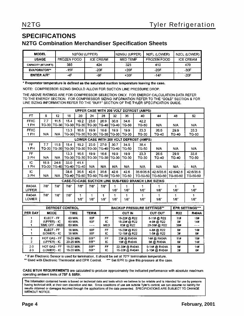
SPECIFICATIONSN2TG Combination Merchandiser Specification Sheets
Installation & Service Manual N2TG
February, 2001 Page 5
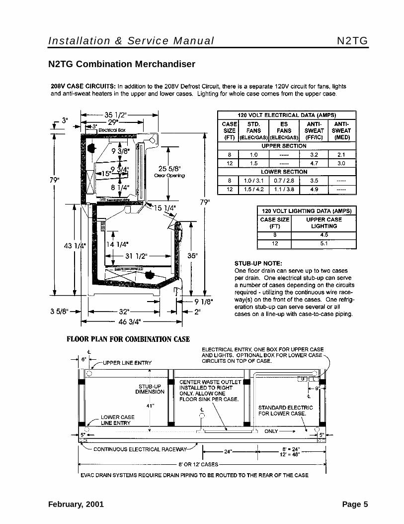
N2TG Combination Merchandiser

N2TG Tyler Refrigeration
Page 6 February, 2001
CAUTIONShipping braces should only be removedfrom case ends that are to be joined. Thisprotects the cases from possible damageduring the line-up procedure.
NOTEA foam gasket is factory installed on oneend of the case. This gasket fits into agroove on the adjoining case when casesare pulled together. Do not depend on thefoam gasket alone to make a good seal!
3. Apply two heavy beads of caulking com-pound from the Filler Kit to the end ofcase at dotted (. . .) and dashed (- - -)lines. Proper caulking provides goodcase refrigeration and sanitation.
INSTALLATION PROCEDURES
Carpentry ProceduresCase Line-Up
Before starting the case line-up, see “Refrig-eration Procedures” in this manual, review thestore layout floorplans and survey the areaswhere case line-ups are going to be installed.
WARNINGThese cases are very heavy and require twoor more people to move and/or positionthem. Improper handling of these casescould result in personal injury.
NOTEAllow at least 3” of air space between thetop back of these cases and store walls orother cases to minimize possible condensa-tion problems. Forced ventilation might benecessary in some situations.
1. Snap chalk lines where the front and rearbase rails of the cases are to be located forthe entire line-up.
NOTEFront and rear edges of base rails shouldalways be used to line-up cases. 6” shimsallow adjoining ends of cases to beshimmed together.
2. Locate highest point on chalk lines as a ref-erence for determining the number ofshims to be placed under the case baserails. Position first case at highest point onthe chalk lines and shim case supports asrequired. Check leveling at hand rails andtop of case and back of case.
Installation & Service Manual N2TG
February, 2001 Page 7
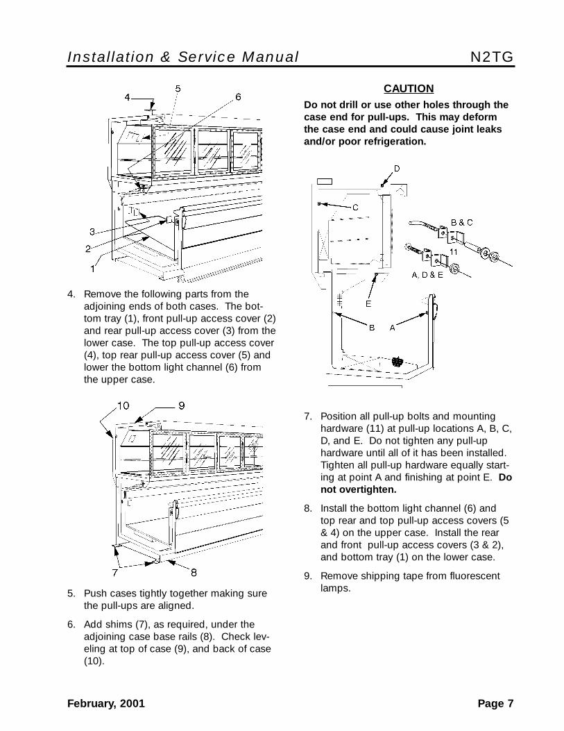
CAUTIONDo not drill or use other holes through thecase end for pull-ups. This may deformthe case end and could cause joint leaksand/or poor refrigeration.
7. Position all pull-up bolts and mountinghardware (11) at pull-up locations A, B, C,D, and E. Do not tighten any pull-uphardware until all of it has been installed.Tighten all pull-up hardware equally start-ing at point A and finishing at point E. Donot overtighten.
8. Install the bottom light channel (6) andtop rear and top pull-up access covers (5& 4) on the upper case. Install the rearand front pull-up access covers (3 & 2),and bottom tray (1) on the lower case.
9. Remove shipping tape from fluorescentlamps.
4. Remove the following parts from theadjoining ends of both cases. The bot-tom tray (1), front pull-up access cover (2)and rear pull-up access cover (3) from thelower case. The top pull-up access cover(4), top rear pull-up access cover (5) andlower the bottom light channel (6) fromthe upper case.
5. Push cases tightly together making surethe pull-ups are aligned.
6. Add shims (7), as required, under theadjoining case base rails (8). Check lev-eling at top of case (9), and back of case(10).
N2TG Tyler Refrigeration
Page 8 February, 2001
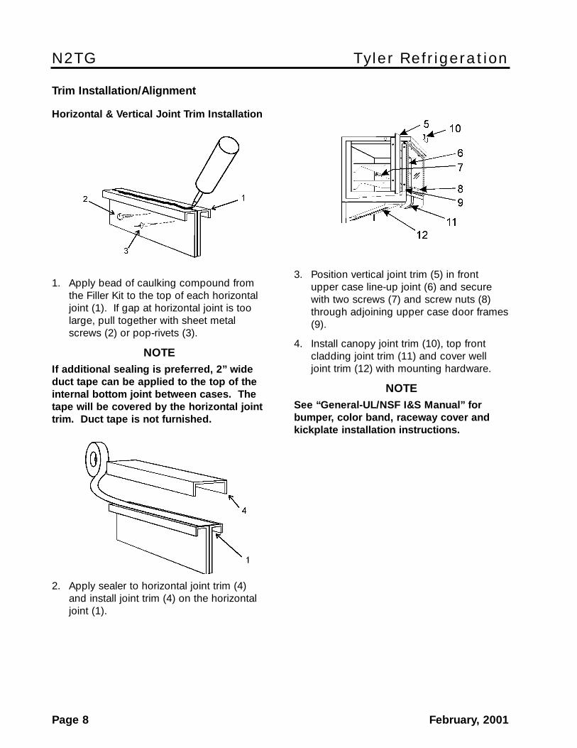
3. Position vertical joint trim (5) in frontupper case line-up joint (6) and securewith two screws (7) and screw nuts (8)through adjoining upper case door frames(9).
4. Install canopy joint trim (10), top frontcladding joint trim (11) and cover welljoint trim (12) with mounting hardware.
NOTESee “General-UL/NSF I&S Manual” forbumper, color band, raceway cover andkickplate installation instructions.
Trim Installation/Alignment
Horizontal & Vertical Joint Trim Installation
1. Apply bead of caulking compound fromthe Filler Kit to the top of each horizontaljoint (1). If gap at horizontal joint is toolarge, pull together with sheet metalscrews (2) or pop-rivets (3).
NOTEIf additional sealing is preferred, 2” wideduct tape can be applied to the top of theinternal bottom joint between cases. Thetape will be covered by the horizontal jointtrim. Duct tape is not furnished.
2. Apply sealer to horizontal joint trim (4)and install joint trim (4) on the horizontaljoint (1).

Installation & Service Manual N2TG
February, 2001 Page 9
Defrost Control Strategy
• High door openings loads associated withhigh food product sales may require twodefrost periods per 24 hour period.
• Pumping down the refrigeration circuit atthe beginning of the defrost period is notrecommended.
Electrical ProceduresElectrical Considerations
CAUTIONMake sure all electrical connections aretight. This prevents burning of electricalterminals and/or premature componentfailure.
NOTEAn electrical box on top of the case hous-es the electrical wiring for the upper caseand case lighting. All other electricalwiring and components can be found inthe raceway at the bottom of the lowercase. All raceway covers will be shippedloose.
Case Fan Circuits
All fan circuits are to be supplied by an unin-terrupted, protected 120V circuit. At casestart-up, the upper case fans will not come onuntil the fan delay thermostat on the coilsenses 20°F. After the upper case has beenrunning, the fan operation is interrupted bythe defrost relay whenever the defrost cycle isinitiated. The defrost relay activates thedefrost and drain pan heaters at the sametime it shuts off the fans. After defrost, thedefrost and drain heaters will shut off andrefrigeration will resume.
NOTEThe upper case fans will not restart untilthe coil temperature reaches 20°F at thefan delay thermostat.
The lower case fan circuit is not cycled,except when equipped for gas defrost. Ongas defrost cases the fan circuit is controlledby a 50/30 klixon.
Refrigeration Procedures
The upper case requires the installation ofrefrigeration lines from the refrigeration stub-ups on the rear of the case to the front of thelower case.
NOTESee “General-UL/NSF I&S Manual” for allother refrigeration procedure information.
N2TG Upper Case ApplicationRequirements
Temperature Control Strategy
• A suction stop EPR valve is the preferredmethod for maintaining temperature con-trol on parallel compressor system appli-cations.
• When using a thermostat and liquid linesolenoid for temperature control, the maxi-mum line-up length that may be controlledis 24 feet.
• The discharge air temperature shall bemaintained between -3°F to -5°F for frozenfood applications and between -10°F to-12°F for ice cream applications.
Temperature Sensor Locations
• The sensor used for temperature controlshall be located in the discharge air.
• If a case controller is used, the sensorused for defrost termination MUST be insu-lated and located where the standarddefrost termination klixon is located. If acase controller is used and the case isdefrosted using electric heaters, thedefrost termination klixon must bereplaced with a 70°F fail safe klixon. Thismeets the safety requirements.
N2TG Tyler Refrigeration
Page 10 February, 2001
NOTEWith gas defrost, the fans will not start untilthe coil temperature reaches 20°F at the fandelay thermostat.
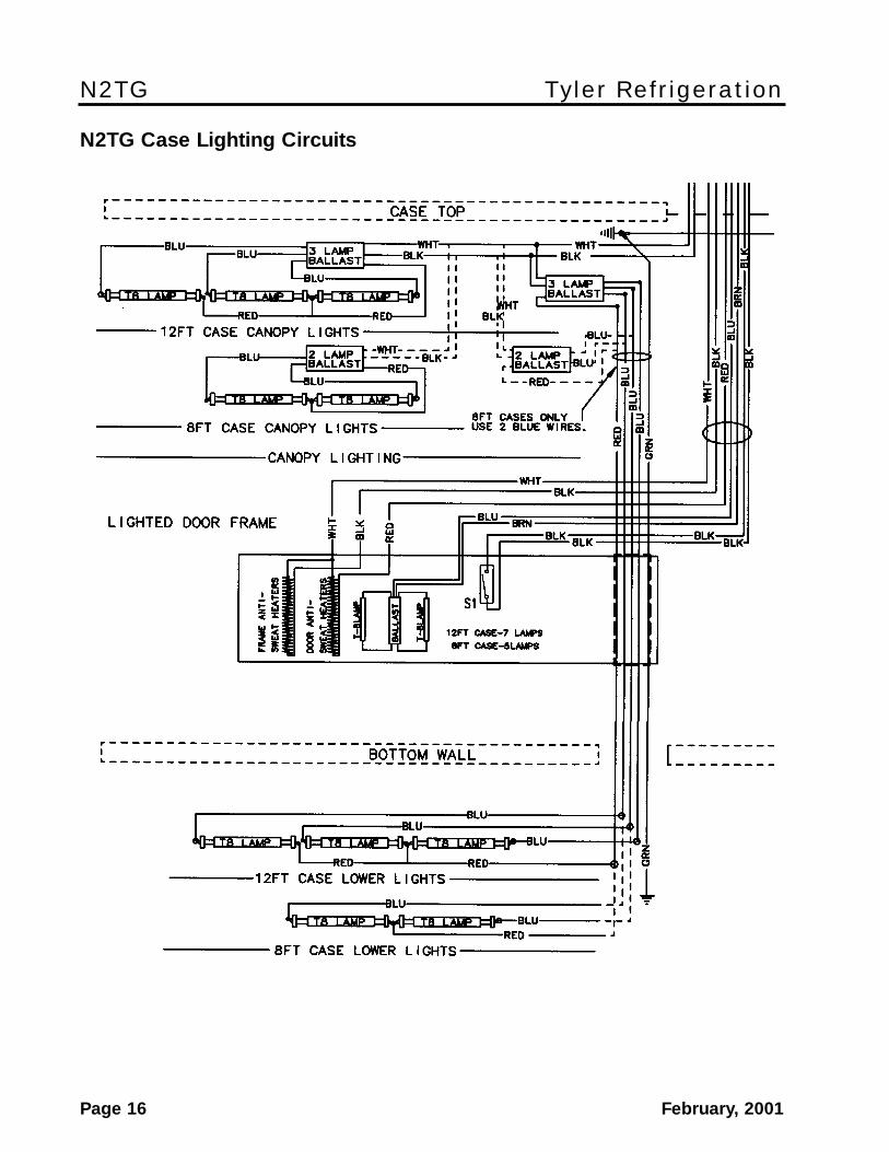
Fluorescent Lamp Circuit
The standard case lighting system is T-8 elec-tronic lamps. The standard lighting is 1-row ofcanopy lights, Prism lighting behind doors, and1-row of horizontal lights above the lower well.
CAUTIONThe light switch should be left off if refrigera-tion is turned off for periods longer than nor-mal defrosting times. This prevents possibledistortion and/or damage to non-metal partsfrom lighting heat.
Anti-Sweat Circuit
Upper cases have anti-sweat heaters in andaround the doors. Lower cases have four anti-sweat heaters. All anti-sweat heaters are wireddirectly to the main power supply so they canoperate at all times.
Defrost Information
See “General-UL/NSF I&S Manual” for opera-tional descriptions for each type of defrostcontrol.
Defrost Control Charts
N2TG Defrost Option Settings
DefrostDefrost Defrosts Duration Term.Type Per Day (Min) Temp.
N2FGU (UPPER)
Electric (FF) 1 60 50°FElectric (IC) 2 60 50°F Gas (FF) 2 18-20 55°F Gas (IC) 2 20-25 55°FOff Time (MT) 1 60 -----
N2FL/N2CL (LOWER)
Electric (FF) 1 36 50°FElectric (IC) 1 36 50°F Gas (FF) 2-3 16-22 55°F Gas (IC) 2-3 16-20 55°F
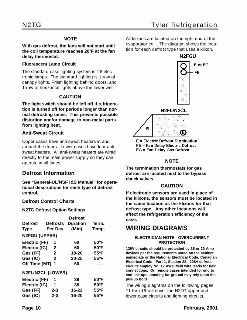
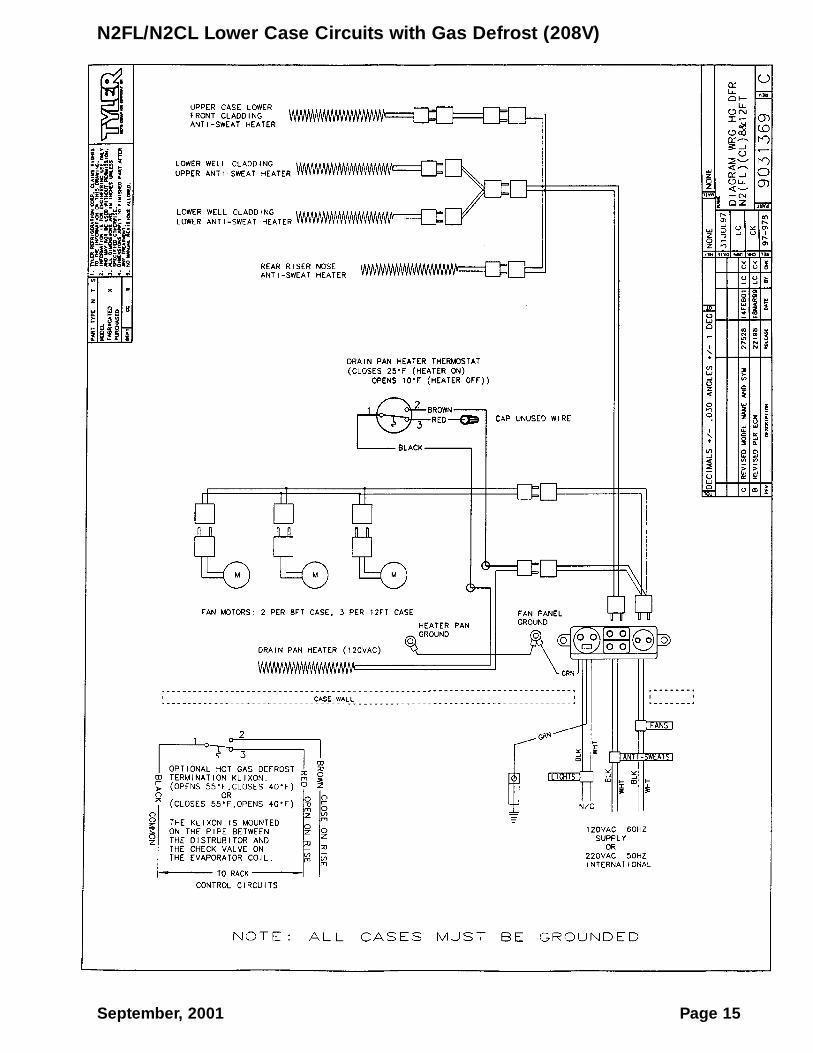
All klixons are located on the right end of theevaporator coil. The diagram shows the loca-tion for each defrost type that uses a klixon.
NOTEThe termination thermostats for gasdefrost are located next to the bypasscheck valves.
CAUTIONIf electronic sensors are used in place ofthe klixons, the sensors must be located inthe same location as the klixons for thatdefrost type. Any other locations willeffect the refrigeration efficiency of thecase.
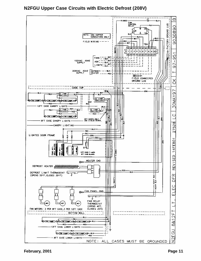
WIRING DIAGRAMSELECTRICIAN NOTE - OVERCURRENT
PROTECTION120V circuits should be protected by 15 or 20 Ampdevices per the requirements noted on the cabinetnameplate or the National Electrical Code, CanadianElectrical Code - Part 1, Section 28. 208V defrostcircuits employ No. 12 AWG field wire leads for fieldconnections. On remote cases intended for end toend line-ups, bonding for ground may rely upon thepull-up bolts.
The wiring diagrams on the following pages11 thru 16 will cover the N2TG upper andlower case circuits and lighting circuits.
February, 2001 Page 11
N2FGU Upper Case Circuits with Electric Defrost (208V)

Page 12 September, 2001
N2FGU Upper Case Circuits with Gas Defrost (208V)
February, 2001 Page 13
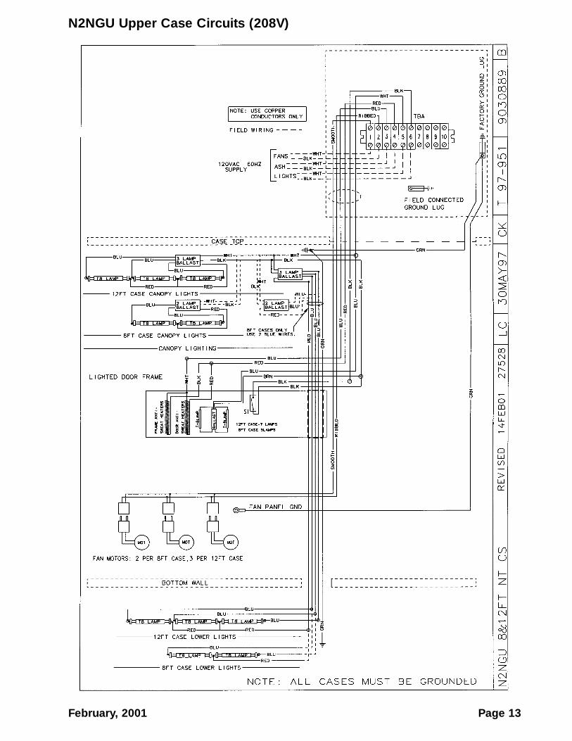
N2NGU Upper Case Circuits (208V)
Page 14 February, 2001
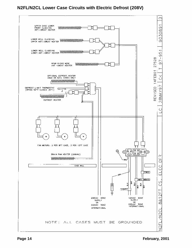
N2FL/N2CL Lower Case Circuits with Electric Defrost (208V)
September, 2001 Page 15
N2FL/N2CL Lower Case Circuits with Gas Defrost (208V)
N2TG Tyler Refrigeration
Page 16 February, 2001
N2TG Case Lighting Circuits
Installation & Service Manual N2TG
February, 2001 Page 17
CLEANING AND SANITATION
Component Removal and Instal-lation Instructions for CleaningShelves and Shelf Brackets(Upper Case)
1. Open door and remove product fromshelves.
2. Push shelves back and then lift up andout to remove them from the shelf brack-ets. Carefully remove shelves through thedoor openings.
3. Remove shelf brackets from slots in rearuprights.
4. After cleaning, replace in reverse order.
Bottom Trays
1. Remove product from the case andremove shelves and shelf brackets fromthe upper case, see this page.
2. Grasp and lift out each of the bottom traysfrom the case interior and carefullyremove through the door openings orfrom the lower case.
3. After cleaning, replace in reverse order.
NSF Product Thermometer
1. On upper case, remove two screws andproduct thermometer access panel fromright top location in the case.
On lower case, remove four screws andproduct thermometer bracket assemblyfrom right rear location in the case.
2. After cleaning, replace product thermome-ter access panel and/or product ther-mometer bracket assembly and securewith mounting screws.
Front Air Ducts
1. Remove bottom trays, see this page.
2. On upper case, lift out front air duct sec-tions and carefully remove through dooropenings.
On lower case, remove screws and front airduct panels from case.
3. After cleaning, replace air ducts, air ductpanels and remaining components inreverse order.
Rear Duct Panels
1. On upper case, remove shelves and bottomtrays, see above.
On lower case, remove bottom trays anddischarge air honeycomb, see this page.
2. Remove mounting screws from rear ductpanel.
3. Carefully remove rear duct panels throughthe door openings in upper case or fromtop opening in lower case.
4. After cleaning, replace in reverse order.
Discharge Air Honeycomb
1. On upper case, loosen screws securingrear retainer plate.
On lower case, remove screws and bottomretainer strip from rear interior of case.
NOTENote position of the honeycomb grid duringremoval so it can be reinstalled the sameway.
2. On upper case, slide rear retainer plateback until the honeycomb grid sections canbe removed from the top duct.
On lower case, remove honeycomb gridsections from rear of case.
CAUTIONImproper installation of the honeycomb gridsection could result in improper air flowand/or poor refrigeration.
3. After cleaning, replace honeycomb gridsections as they were removed and securewith the rear retainer plate or bottom retain-er strip and screws.
N2TG Tyler Refrigeration
Page 18 February, 2001
Top Duct (Upper Case)
1. Remove shelves and shelf brackets, seepage 17.
2. Remove screws, rear retainer plate andhoneycomb grid sections from top front ofcase, see page 17.
3. Remove screws and top duct from case.
4. After cleaning, replace top duct andremaining components in reverse order.
Front Cladding
1. Remove mounting screws, upper frontcladding joint trim and upper frontcladding from bottom of upper case.
2. Remove front kickplate and racewaycover from bottom of lower case.
3. Remove screws from bottom and top oflower front cladding and pull claddingdown to remove it from behind the edgeof the bumper retainer.
3. After cleaning, replace lower frontcladding, upper front cladding andremaining front components in reverseorder.
Installation & Service Manual N2TG
February, 2001 Page 19
SERVICE INSTRUCTIONSSee “General-UL/NSF I&S Manual” for fanblade and motor replacement, color bandand bumper replacement and racewaycover removal instructions.
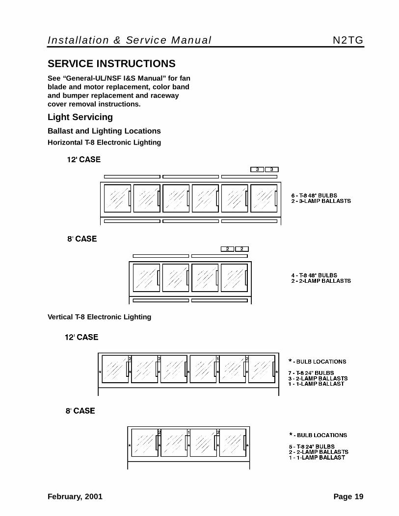
Light ServicingBallast and Lighting LocationsHorizontal T-8 Electronic Lighting
Vertical T-8 Electronic Lighting
N2TG Tyler Refrigeration
Page 20 February, 2001
Lamp Replacement
CAUTIONShut off light switch or disconnect powersupply before changing a lamp. Lightingsystem power and/or ballast surges canburn out adjacent lamps if power is left on.
NOTESee “T-8 Lamp Replacement” in “General-UL/NSF I&S Manual” for canopy and/oropen well lamp replacement instructions.
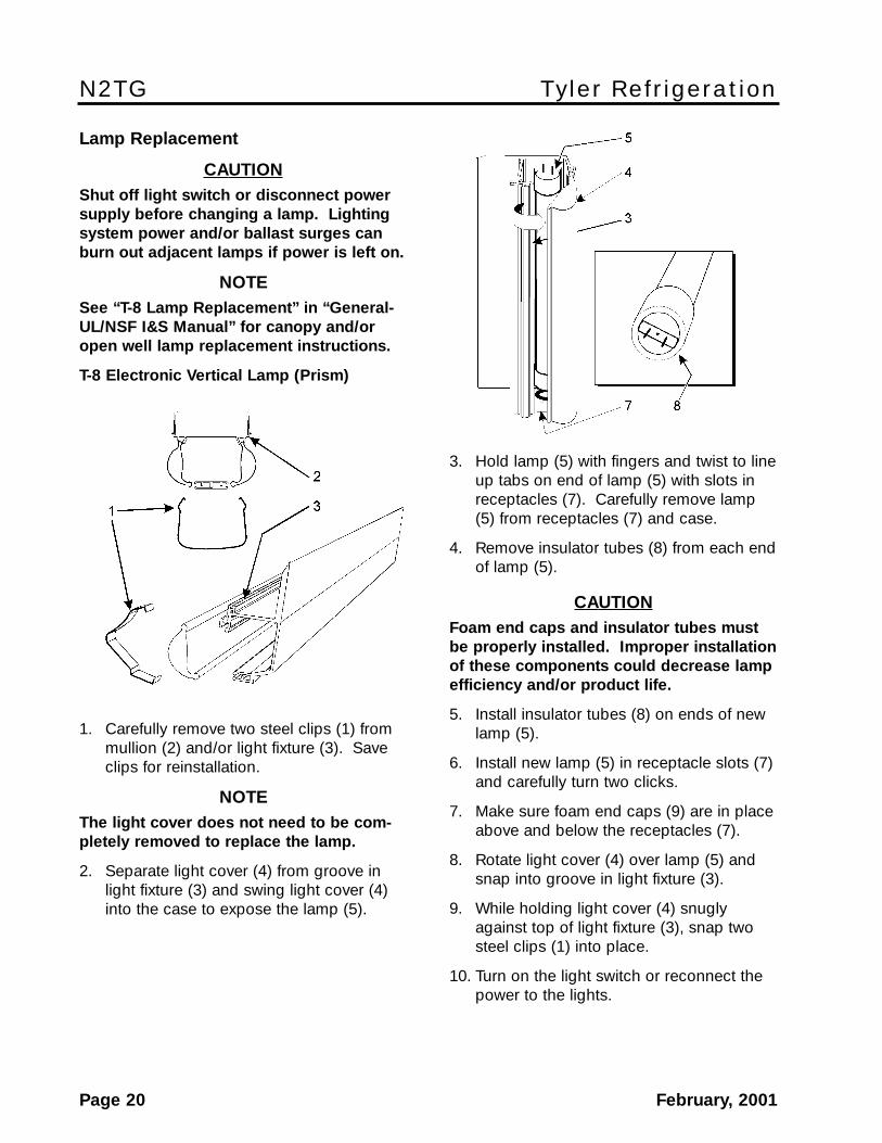
T-8 Electronic Vertical Lamp (Prism)
1. Carefully remove two steel clips (1) frommullion (2) and/or light fixture (3). Saveclips for reinstallation.
NOTEThe light cover does not need to be com-pletely removed to replace the lamp.
2. Separate light cover (4) from groove inlight fixture (3) and swing light cover (4)into the case to expose the lamp (5).
3. Hold lamp (5) with fingers and twist to lineup tabs on end of lamp (5) with slots inreceptacles (7). Carefully remove lamp(5) from receptacles (7) and case.
4. Remove insulator tubes (8) from each endof lamp (5).
CAUTIONFoam end caps and insulator tubes mustbe properly installed. Improper installationof these components could decrease lampefficiency and/or product life.
5. Install insulator tubes (8) on ends of newlamp (5).
6. Install new lamp (5) in receptacle slots (7)and carefully turn two clicks.
7. Make sure foam end caps (9) are in placeabove and below the receptacles (7).
8. Rotate light cover (4) over lamp (5) andsnap into groove in light fixture (3).
9. While holding light cover (4) snuglyagainst top of light fixture (3), snap twosteel clips (1) into place.
10. Turn on the light switch or reconnect thepower to the lights.
Installation & Service Manual N2TG
February, 2001 Page 21
Electronic Ballast Replacement (Prism Lighting)
WARNING
Before replacing a ballast, make sure allpower is off to the case. Electrical servic-ing should always be done by a qualifiedelectrician. Improper servicing couldresult in product damage and/or personalinjury.
NOTERefer to T-8 ballast location page andwiring diagrams in this manual for specificmodel information.
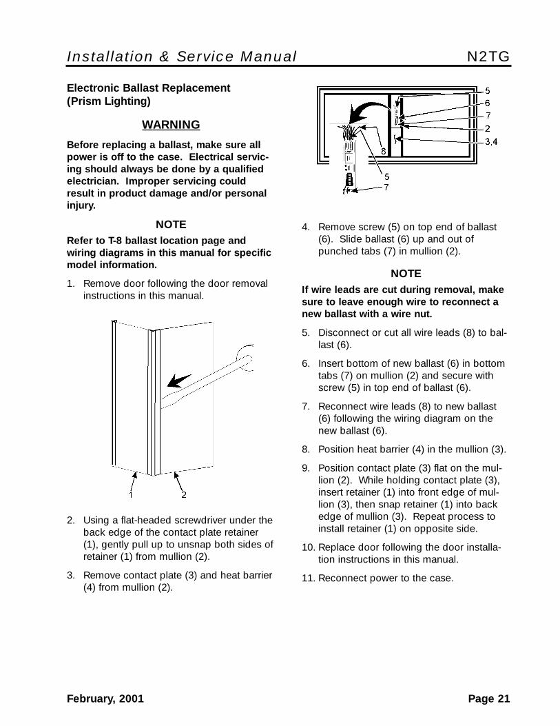
1. Remove door following the door removalinstructions in this manual.
2. Using a flat-headed screwdriver under theback edge of the contact plate retainer(1), gently pull up to unsnap both sides ofretainer (1) from mullion (2).
3. Remove contact plate (3) and heat barrier(4) from mullion (2).
4. Remove screw (5) on top end of ballast(6). Slide ballast (6) up and out ofpunched tabs (7) in mullion (2).
NOTEIf wire leads are cut during removal, makesure to leave enough wire to reconnect anew ballast with a wire nut.
5. Disconnect or cut all wire leads (8) to bal-last (6).
6. Insert bottom of new ballast (6) in bottomtabs (7) on mullion (2) and secure withscrew (5) in top end of ballast (6).
7. Reconnect wire leads (8) to new ballast(6) following the wiring diagram on thenew ballast (6).
8. Position heat barrier (4) in the mullion (3).
9. Position contact plate (3) flat on the mul-lion (2). While holding contact plate (3),insert retainer (1) into front edge of mul-lion (3), then snap retainer (1) into backedge of mullion (3). Repeat process toinstall retainer (1) on opposite side.
10. Replace door following the door installa-tion instructions in this manual.
11. Reconnect power to the case.
N2TG Tyler Refrigeration
Page 22 February, 2001
(Horizontal Lighting)
WARNING
Before replacing a ballast, make sure allpower is off to the case. Electrical servic-ing should always be done by a qualifiedelectrician. Improper servicing couldresult in product damage and/or personalinjury.
NOTE• Refer to ballast & lighting location page
and wiring diagrams in this manual forspecific model information.
• If wire leads are cut during removal,make sure to leave enough wire toreconnect a new ballast with a wire nut.
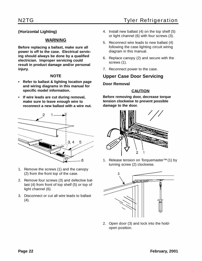
1. Remove the screws (1) and the canopy(2) from the front top of the case.
2. Remove four screws (3) and defective bal-last (4) from front of top shelf (5) or top oflight channel (6).
3. Disconnect or cut all wire leads to ballast(4).
4. Install new ballast (4) on the top shelf (5)or light channel (6) with four screws (3).
5. Reconnect wire leads to new ballast (4)following the case lighting circuit wiringdiagram in this manual.
6. Replace canopy (2) and secure with thescrews (1).
7. Reconnect power to the case.
Upper Case Door Servicing
Door Removal
CAUTIONBefore removing door, decrease torquetension clockwise to prevent possibledamage to the door.
1. Release tension on Torquemaster™ (1) byturning screw (2) clockwise.
2. Open door (3) and lock into the hold-open position.
Installation & Service Manual N2TG
February, 2001 Page 23
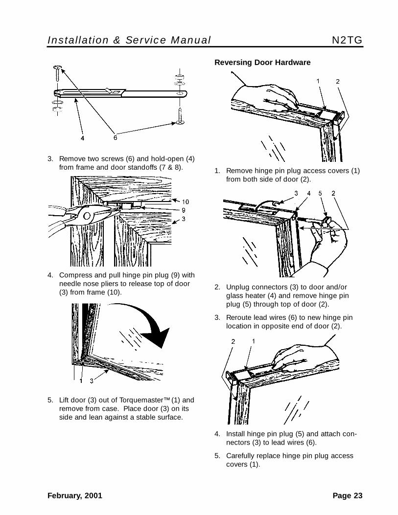
3. Remove two screws (6) and hold-open (4)from frame and door standoffs (7 & 8).
4. Compress and pull hinge pin plug (9) withneedle nose pliers to release top of door(3) from frame (10).
5. Lift door (3) out of Torquemaster™ (1) andremove from case. Place door (3) on itsside and lean against a stable surface.
Reversing Door Hardware
1. Remove hinge pin plug access covers (1)from both side of door (2).
2. Unplug connectors (3) to door and/orglass heater (4) and remove hinge pinplug (5) through top of door (2).
3. Reroute lead wires (6) to new hinge pinlocation in opposite end of door (2).
4. Install hinge pin plug (5) and attach con-nectors (3) to lead wires (6).
5. Carefully replace hinge pin plug accesscovers (1).
N2TG Tyler Refrigeration
Page 24 February, 2001
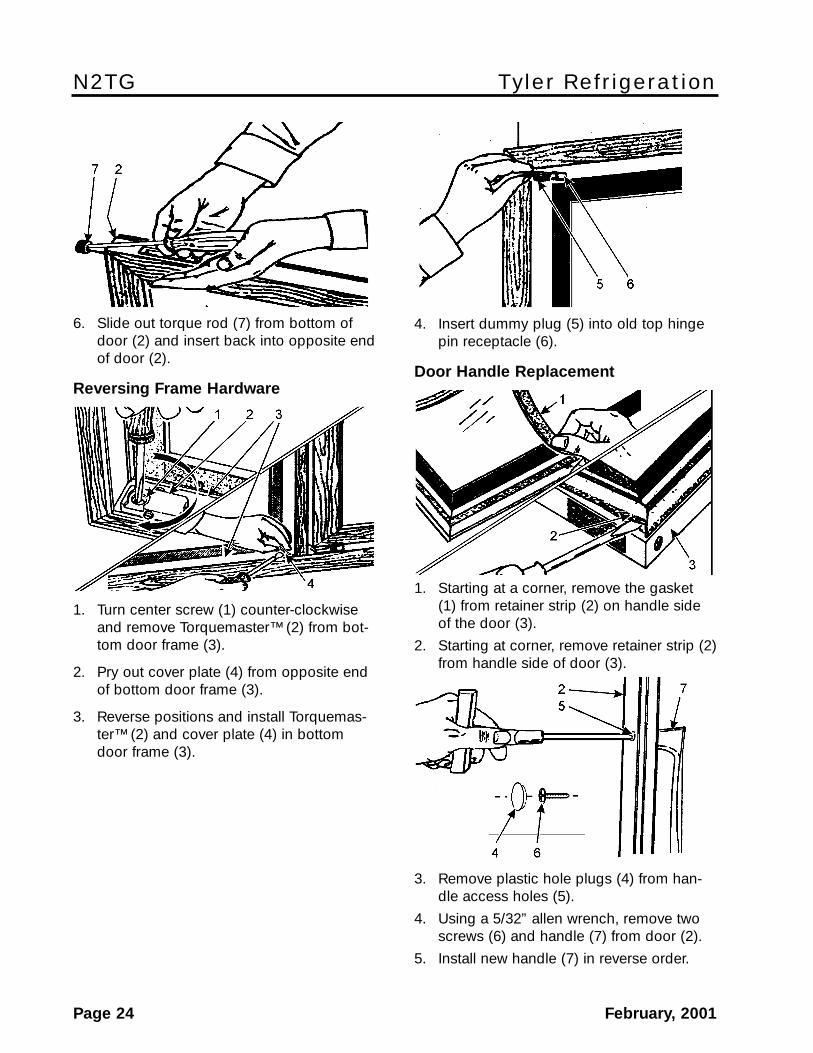
4. Insert dummy plug (5) into old top hingepin receptacle (6).
Door Handle Replacement
1. Starting at a corner, remove the gasket(1) from retainer strip (2) on handle sideof the door (3).
2. Starting at corner, remove retainer strip (2)from handle side of door (3).
3. Remove plastic hole plugs (4) from han-dle access holes (5).
4. Using a 5/32” allen wrench, remove twoscrews (6) and handle (7) from door (2).
5. Install new handle (7) in reverse order.
6. Slide out torque rod (7) from bottom ofdoor (2) and insert back into opposite endof door (2).
Reversing Frame Hardware
1. Turn center screw (1) counter-clockwiseand remove Torquemaster™ (2) from bot-tom door frame (3).
2. Pry out cover plate (4) from opposite endof bottom door frame (3).
3. Reverse positions and install Torquemas-ter™ (2) and cover plate (4) in bottomdoor frame (3).
Installation & Service Manual N2TG
February, 2001 Page 25
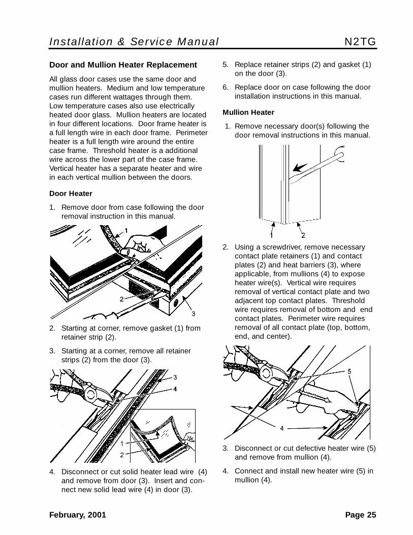
5. Replace retainer strips (2) and gasket (1)on the door (3).
6. Replace door on case following the doorinstallation instructions in this manual.
Mullion Heater
1. Remove necessary door(s) following thedoor removal instructions in this manual.
2. Using a screwdriver, remove necessarycontact plate retainers (1) and contactplates (2) and heat barriers (3), whereapplicable, from mullions (4) to exposeheater wire(s). Vertical wire requiresremoval of vertical contact plate and twoadjacent top contact plates. Thresholdwire requires removal of bottom and endcontact plates. Perimeter wire requiresremoval of all contact plate (top, bottom,end, and center).
3. Disconnect or cut defective heater wire (5)and remove from mullion (4).
4. Connect and install new heater wire (5) inmullion (4).
Door and Mullion Heater Replacement
All glass door cases use the same door andmullion heaters. Medium and low temperaturecases run different wattages through them.Low temperature cases also use electricallyheated door glass. Mullion heaters are locatedin four different locations. Door frame heater isa full length wire in each door frame. Perimeterheater is a full length wire around the entirecase frame. Threshold heater is a additionalwire across the lower part of the case frame.Vertical heater has a separate heater and wirein each vertical mullion between the doors.
Door Heater
1. Remove door from case following the doorremoval instruction in this manual.
2. Starting at corner, remove gasket (1) fromretainer strip (2).
3. Starting at a corner, remove all retainerstrips (2) from the door (3).
4. Disconnect or cut solid heater lead wire (4)and remove from door (3). Insert and con-nect new solid lead wire (4) in door (3).
N2TG Tyler Refrigeration
Page 26 February, 2001
5. Replace heat barriers (3), where applica-ble, and contact plates (2) and contact-plate retainers (1) on mullions (4)
6. Replace door(s) following the door instal-lation instructions in this manual.
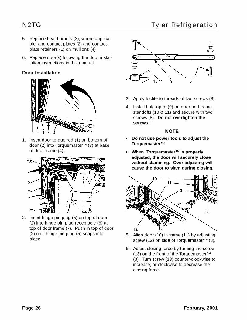
Door Installation
1. Insert door torque rod (1) on bottom ofdoor (2) into Torquemaster™ (3) at baseof door frame (4).
2. Insert hinge pin plug (5) on top of door(2) into hinge pin plug receptacle (6) attop of door frame (7). Push in top of door(2) until hinge pin plug (5) snaps intoplace.
3. Apply loctite to threads of two screws (8).
4. Install hold-open (9) on door and framestandoffs (10 & 11) and secure with twoscrews (8). Do not overtighten thescrews.
NOTE• Do not use power tools to adjust the
Torquemaster™.
• When Torquemaster™ is properlyadjusted, the door will securely closewithout slamming. Over adjusting willcause the door to slam during closing.
5. Align door (10) in frame (11) by adjustingscrew (12) on side of Torquemaster™ (3).
6. Adjust closing force by turning the screw(13) on the front of the Torquemaster™(3). Turn screw (13) counter-clockwise toincrease, or clockwise to decrease theclosing force.
Installation & Service Manual N2TG
February, 2001 Page 27
Case Defrost & Dan Pan HeaterReplacement
WWAARRNNIINNGG
Before replacing defrost or drain panheater, shut off electrical power to the caseto avoid personal injury and/or death.
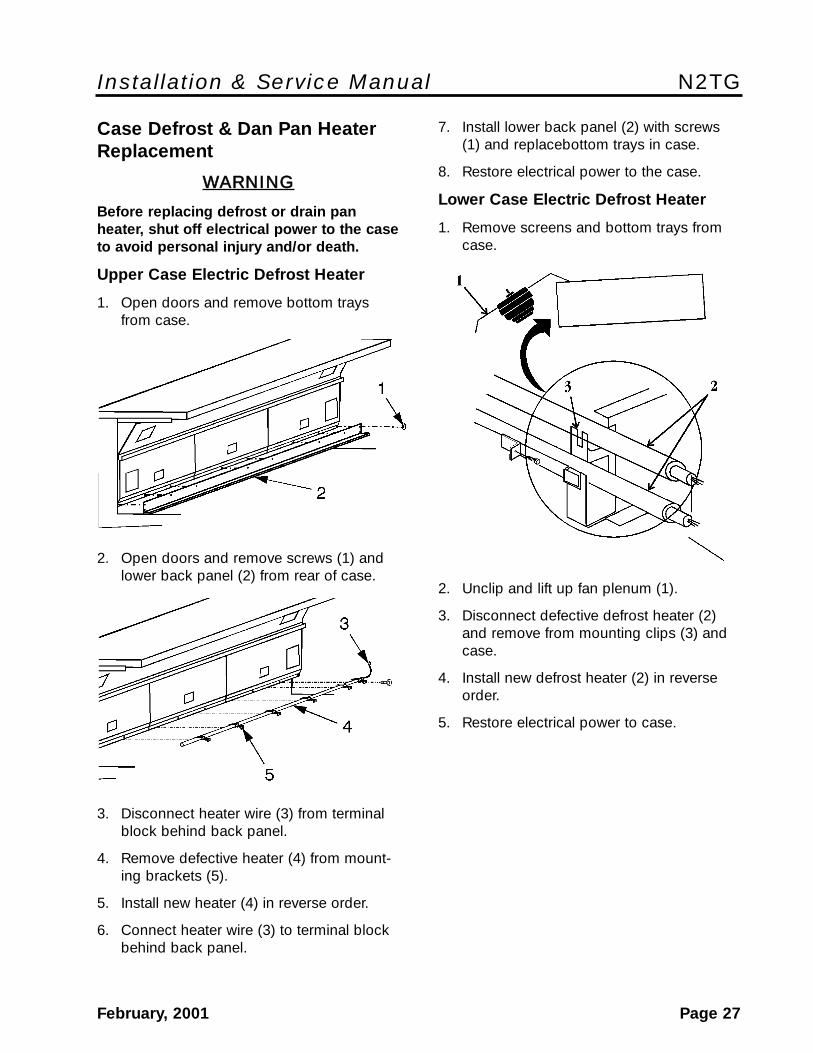
Upper Case Electric Defrost Heater
1. Open doors and remove bottom traysfrom case.
2. Open doors and remove screws (1) andlower back panel (2) from rear of case.
3. Disconnect heater wire (3) from terminalblock behind back panel.
4. Remove defective heater (4) from mount-ing brackets (5).
5. Install new heater (4) in reverse order.
6. Connect heater wire (3) to terminal blockbehind back panel.
7. Install lower back panel (2) with screws(1) and replacebottom trays in case.
8. Restore electrical power to the case.
Lower Case Electric Defrost Heater
1. Remove screens and bottom trays fromcase.
2. Unclip and lift up fan plenum (1).
3. Disconnect defective defrost heater (2)and remove from mounting clips (3) andcase.
4. Install new defrost heater (2) in reverseorder.
5. Restore electrical power to case.

N2TG Tyler Refrigeration
Page 28 February, 2001
Fan Locations and Access
The upper case fans (1) are located behindthe slanted upper panel. Remove the upperpanel to access the upper case fan panel.The lower case fans (2) are located in thebottom of the lower well. Remove the bottomtrays to access the lower case fan panel.
See “General-UL/NSF I&S Manual” for fanblade and motor replacement instructions.
Lower Case Drain Heater
1. Remove screens and bottom trays fromcase.
NOTE
Note the positioning of the drain heaterwires before disconnecting for properinstallation of the new heater.
2. Disconnect drain heater wires (1) at thewire nut connections in the bottom of thecase.
3. Lift up drain trap heater support (2) andremove defective drain heater (3) frommounting brackets (4).
4. Install new drain heater (3) in mountingbrackets (4) and lower drain trap heatersupport (2).
5. Connect heater wires (1) as removed andsecure with wire nuts at connections.
6. Install bottom trays and screens in case.
7. Restore electrical power to the case.
Installation & Service Manual N2TG
February, 2001 Page 29
Anti-Sweat Replacement
WWAARRNNIINNGG
Shut off or disconnect power supply tocase before changing an anti-sweat.Electrical power from wire ends coulddamage other components and/or causepersonal injury or death.
NOTE
See “Upper Case Door Servicing” sectionin this manual for upper case anti-sweatreplacement instructions.
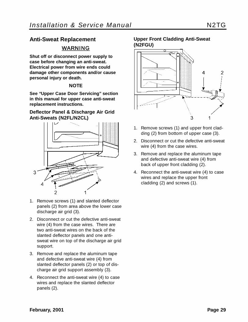
Deflector Panel & Discharge Air Grid Anti-Sweats (N2FL/N2CL)
1. Remove screws (1) and slanted deflectorpanels (2) from area above the lower casedischarge air grid (3).
2. Disconnect or cut the defective anti-sweatwire (4) from the case wires. There aretwo anti-sweat wires on the back of theslanted deflector panels and one anti-sweat wire on top of the discharge air gridsupport.
3. Remove and replace the aluminum tapeand defective anti-sweat wire (4) fromslanted deflector panels (2) or top of dis-charge air grid support assembly (3).
4. Reconnect the anti-sweat wire (4) to casewires and replace the slanted deflectorpanels (2).
Upper Front Cladding Anti-Sweat(N2FGU)
1. Remove screws (1) and upper front clad-ding (2) from bottom of upper case (3).
2. Disconnect or cut the defective anti-sweatwire (4) from the case wires.
3. Remove and replace the aluminum tapeand defective anti-sweat wire (4) fromback of upper front cladding (2).
4. Reconnect the anti-sweat wire (4) to casewires and replace the upper frontcladding (2) and screws (1).
N2TG Tyler Refrigeration
Page 30 February, 2001
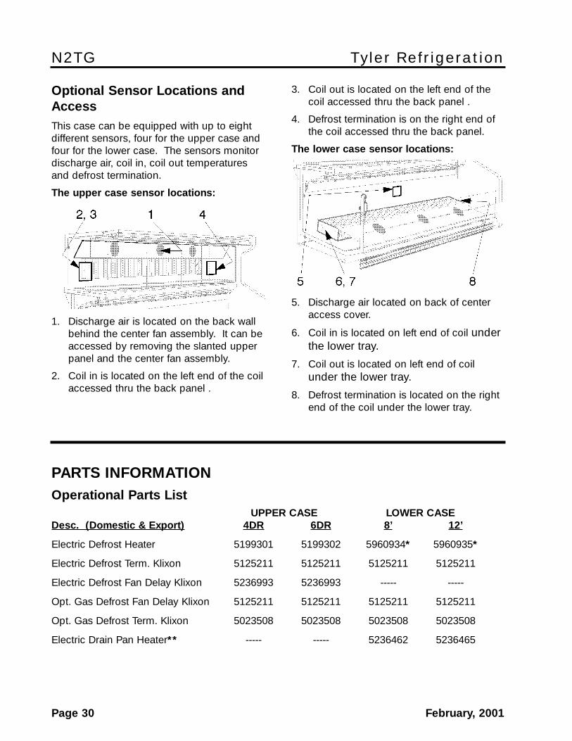
Optional Sensor Locations andAccessThis case can be equipped with up to eightdifferent sensors, four for the upper case andfour for the lower case. The sensors monitordischarge air, coil in, coil out temperaturesand defrost termination.
The upper case sensor locations:
1. Discharge air is located on the back wallbehind the center fan assembly. It can beaccessed by removing the slanted upperpanel and the center fan assembly.
2. Coil in is located on the left end of the coilaccessed thru the back panel .
3. Coil out is located on the left end of thecoil accessed thru the back panel .
4. Defrost termination is on the right end ofthe coil accessed thru the back panel.
The lower case sensor locations:
5. Discharge air located on back of centeraccess cover.
6. Coil in is located on left end of coil underthe lower tray.
7. Coil out is located on left end of coilunder the lower tray.
8. Defrost termination is located on the rightend of the coil under the lower tray.
PARTS INFORMATIONOperational Parts List
UPPER CASE LOWER CASEDesc. (Domestic & Export) 4DR 6DR 8’ 12’
Electric Defrost Heater 5199301 5199302 5960934* 5960935*
Electric Defrost Term. Klixon 5125211 5125211 5125211 5125211
Electric Defrost Fan Delay Klixon 5236993 5236993 ----- -----
Opt. Gas Defrost Fan Delay Klixon 5125211 5125211 5125211 5125211
Opt. Gas Defrost Term. Klixon 5023508 5023508 5023508 5023508
Electric Drain Pan Heater** ----- ----- 5236462 5236465

Installation & Service Manual N2TG
February, 2001 Page 31
UPPER CASE LOWER CASEDesc. (Domestic & Export) 4DR 6DR 8’ 12’
T-8 Vert. Elek. Ballast (1 lamp) 5092559 5092559 ----- -----
T-8 Vert. Elek. Ballast (2 lamp) 5092560 (2) 5092560 (3) ----- -----
T-8 Horz. Elek. Ballast (2 lamp) 5991029 (2) ----- ----- -----
T-8 Horz. Elek. Ballast (3 lamp) ----- 5991030 (2) ----- -----
T-8 Lampholder 5232279 5232279 ----- -----
Fan Motors (dom.) 5125532 5125532 5125532 51255325 Watt 5 Watt 5 Watt 5 Watt
Fan Motors (exp.) 5205538 5205538 5126572 51265725 Watt 5 Watt 5 Watt 5 Watt
Fan Blades (7.75” 32° 3B)(dom./exp.) 5126000 5126000 ----- -----
(6” 21° 3B)(dom.) ----- ----- 5105621 5105621
(6” 27° 3B)(exp.) ----- ----- 5104294 5104294
Fan Motor Brackets 5120098 5120098 5213132 5213132
Fan Bracket Plate 9041077 9041077 9041077 9041077
Opt. ECM Fan Motors (dom.) ----- ----- 9025002 90250028 Watt 8 Watt
Opt. ECM Fan Blades ----- ----- 5968039 5968039(6” 21° 3B)(dom.)
Opt. ECM Fan Motor Brackets ----- ----- 5205279 5205279
Fan Relay (electric defrost) 5197868 5197868 ----- -----
Lwr. Case Anti-Sweat Heater Wire(Upr. Frt. Cladding/Lo-Watt)(dom.) ----- ----- 5124216 5124217
(exp.) 5081147 5081148
(Slntd. Deflec. Panel/Lo-Watt)(dom.) ----- ----- 5124216 5124217(exp.) 5081147 5081148
(Slntd. Deflec. Panel/Hi-Watt)(dom.) ----- ----- 5124818 5124819(exp.) 5081149 5081150
(Discharge Air/Hi-Watt)(dom.) ----- ----- 5124818 5124819(exp.) 5081149 5081150
NSF Product Thermometer 5967100 5967100 5967100 5967100
*N2FL-Qty. 1 / N2CL-Qty. 2 **N2CL only
For information on operational parts not listed above contact the TYLER Service PartsDepartment.

N2TG Tyler Refrigeration
Page 32 February, 2001
Cladding and Trim Parts List
Item Description 8’ / 4DR 12’ / 6DR
1 Bumper End Trim color per order
2 Upper Front Cladding, Painted 5968090 5968091
3 Bumper Retainer/Hand Rail color per order
Screw 9025833 (18) 9025833 (26)
4 Color Band, Painted 9020981 9020982
5 Bumper color per order
6 Lower Front Cladding, Painted 9025209 9025210
Cladding Retainer 9300197 (4) 9300197 (4)
Screw 5183536 (8) 5183536 (8)
7 Raceway Cover color per order
8 Kickplate color per order
Screw 5183536 (6) 5183536 (8)
9 Raceway Cover Retainer 9300600 (4) 9300600 (6)
Screw 5183536 (4) 5183536 (6)
10 Kickplate Support Assy. 9042341 (3) 9042341 (4)
Shoulder Screw 9025833 (12) 9025833 (16)
11 Raceway Cover Backer color per order
12 Raceway Cover End Trim color per order
13 Raceway 9300218 9300219
Screw 5183536 (18) 5183536 (18)
Raceway Support 9041321 (6) 9041321 (8)
Raceway CVR Support 9041325 (6) 9041325 (8)
Screw 5183536 (12) 5183536 (16)
14 RH End Close-off, Painted 9030856 9030856
LH End Close-off, Painted 9030855 9030855
Screw 5048626 (4) 5048626 (4)
15 Bumper Backer color per order
16 Horizontal Joint Trim 5127503 5127503
17 Color Band Backer, Painted 9025982 9025982
18 Hand Rail Backer 9025316 9025316
19 Front Duct Joint Trim 5203017 5203017
Screw 5105037 (4) 5105037 (4)
20 Upper Front Cladding Joint Trim, Painted 5217592 5217592
Screw 5205439 (4) 5205439 (4)
Installation & Service Manual N2TG
February, 2001 Page 33
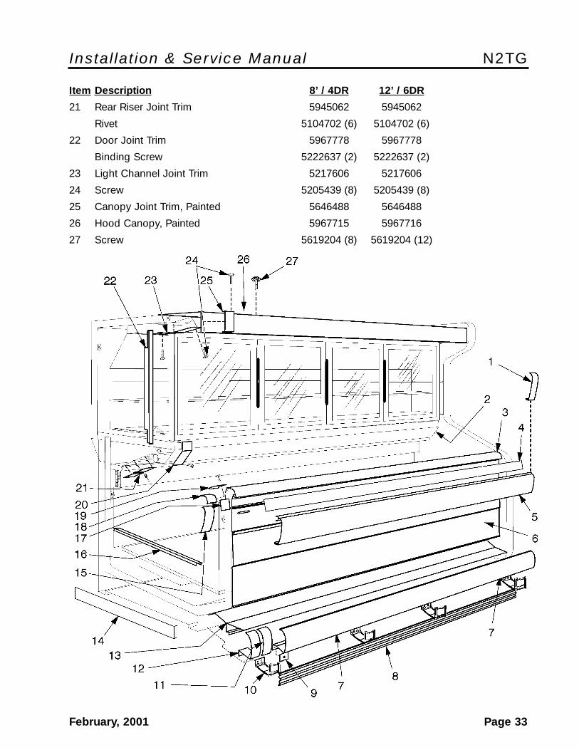
Item Description 8’ / 4DR 12’ / 6DR
21 Rear Riser Joint Trim 5945062 5945062
Rivet 5104702 (6) 5104702 (6)
22 Door Joint Trim 5967778 5967778
Binding Screw 5222637 (2) 5222637 (2)
23 Light Channel Joint Trim 5217606 5217606
24 Screw 5205439 (8) 5205439 (8)
25 Canopy Joint Trim, Painted 5646488 5646488
26 Hood Canopy, Painted 5967715 5967716
27 Screw 5619204 (8) 5619204 (12)