installation, service and maintenance … de instruccions...2013/05 1.safety 3 1. safety 1.1....
TRANSCRIPT
INSTALLATION, SERVICE AND MAINTENANCE INSTRUCTIONS
BUTTERFLY VALVE
INOXPA, S.A. c/Telers, 54 Aptdo. 174
E-17820 Banyoles Girona (Spain)
Tel. : (34) 972 - 57 52 00 Fax. : (34) 972 - 57 55 02 Email: [email protected]
www.inoxpa.com
Original Manual 10.001.30.00EN
(G) 2013/05

EC DECLARATION OF CONFORMITY (according to Directive 2006/42/CE, annex II, part A)
Manufacturer: INOXPA, S.A.
C/ Telers, 54
17820 Banyoles (Girona) - SPAIN
Hereby declares, that the product:
VALVE BUTTERFLY
Name Type
conforms to the specifications of the Council Directive:
Machine Directive 2006/42/EC, and complies with the essential requirements of the Directive and Harmonised Standards:
UNE-EN ISO 12100-1/2:2004 UNE-EN 953:1997 UNE-EN ISO 13732-1:2007
Pressure Equipment Directive 97/23/CE, the equipment has been designed and manufactured in accordance with the requirements of the Directive.
Max operating P.: DN-10 to DN-100/4” =10 bar / DN-125/5” to DN-150/6” =8 bar / DN-200/8” =5 bar
Diameter: X < or = DN-25
Equipment category: SEP = Sound Engineering Practice, determined according to Article 3 Section 1.3.a, first paragraph Annex II, Table 6 This material SHALL NOT carry CE marking.
Diameter: DN-25 < X < or = DN-100
Equipment category: Category I, determined according Article 3 Section 1.3.a, first paragraph Annex II, Table 6 This material SHALL carry CE marking. Conformity Assessment Module: Module A
Diameter: DN-125/150/200
This valves are subject to the following assessment procedure, Module A, Category I, fluids Group 2. This material SHALL carry CE marking.
In compliance with the Regulations (CE) nº 1935/2004, relating to materials and articles intended to come into contact with foodstuff (repeal Directive 89/109/CEE), the materials in contact with the product do not transfer their components in quantities which may jeopardise consumer’s health or safety.
Declaration of Incorporation (Directive 2006/42/CE, annex II, part B):
The equipments above mentioned won’t put to operation till the machine into or onto it will be installed must comply with the stipulations of the Machine Directive.
Banyoles, 2013
DAVID REYERO Technical manager

2013/05 1.Safety 3
1. Safety
1.1. INSTRUCTION MANUAL. This instruction manual contains the basic instructions that must be followed during installation, commissioning and maintenance work. The information given herein is base don the up-to-date data available. INOXPA reserves the right to modif. This instructions manual without having to give prior notice. 1.2. COMMISSIONING. This instructions manual contains both essential and useful information in order that your valve be properly handled and maintained. Not only should the safety instructions set forth in this chapter be obeyed, but all tose special measures and recommendations that have been added to other chapters herein must also be observed. It is extremely important that these instructions be kept in a set place near the installation.
1.3. SAFETY. 1.3.1. Warning signs.
Danger for people in general
Danger of injury caused by rotating parts of the equipment
Peligro! Electricity
Danger! Caustic or corrosive agents
Danger! Suspended loads
Danger to the proper operating of the machine
Obligation to ensure safety at work
Use of safety goggles obligatory
1.4. GENERAL SAFETY INSTRUCTIONS.
Please read the instruction manual carefully befote installing and commissioning the valve. Should you have any doubts or queries, contact INOXPA.
1.4.1. During the installation procedure.
You must always bear in mind the Technical Specifications set forth in Chapter 8. The installation and use of the valve / actuator must always be carried out in accordance with health
and safety rules that are to be applied. Before putting tha valve / actuator into operation, check to make sure that it has been correctly assembled and that the shaft has been perfectly aligned. Incorrect alignement and / or excessive force applied during the securing of the valve / actuator may give rise to serious mechanical problems.
During the installation procedure, all the electrical work must be carried out by duly authorised personnel.
1.4.2. During operation.
You must always bear in mind the Technical Specifications set forth in Chapter 8. The limit values that
have been set must NEVER be exceeded.

4 1.Safety 2013/05
NEVER touch the valve and / or pipes that come into contact with the liquid whenever the valve in in service. If it works with hot products, there is a risk of getting burned. Do not tamper with the actuator if there is a breakdown; the springs are not protected.
The valve / actuator has rotating parts. Do not put your hands or fingers in the coupling that joins the valve and actuator when the compressed air has been connected. Any such action may give rise to serious injury.
1.4.3. During maintenance work.
You must always bear in mind the Technical Specifications set forth in Chapter 8. NEVER dismantle the valve down until the pipes have been drained. Remember that the liquid contained in the pipes can be dangerous or extremely hot. For situations of this type, please, consult the prevailing regulations in the country in question. Do not leave loose parts on the floor.
All electrical work must be carried out by duly authorised personnel.
1.4.4. Compliance with the instructions. Any failure to comply with the instructions could endanger the operators, the environment and the machine, and could result in the loss of any rights to claim damages. Failure to observe these instructions could carry the following risks:
Serious operacional failure of the machina / plant. Specific maintenance and faul repair procedures. The treta of electrical, mechanical and chemical risks. The environment may be endangered by the substances released.
1.5. GUARENTEE. Any guarantee will immediately become fully null and void, and what is more, we will be fully compensated for any civil liability claim made against us by third parties, in the event that:
The installation and maintenance work has not been carried out in accordance with the instructions set forth in this manual.
The repairs have not been carried out Esther by a member of our staff, or have been done without our company having issued prior written authorisation.
The parts used are not original INOXPA pieces. Modifications have been carried out without prior griten consent. The material has been badly, incorrectly or negligently used, or has be used in accordance with the instructions and end
set forth in this manual. The general delivery conditions already in your possesson also apply.
Should you have any doubts or require more in-depth explanations about particular data (adjustments, assembly, dismontling, …) please do not hesitate to contact us.

2013/05 2.Contents 5
2. Contents
1. Safety 3
1.1. instrucTion MANUAL. ...................................................................................................... 3
1.2. COMMISSIONING. ......................................................................................................... 3
1.3. SAFETY. ........................................................................................................................ 3
1.4. GENERAL SAFETY InstrucTIONS. ..................................................................................... 3
1.5. GUARENTEE. ................................................................................................................. 4
2. Contents 5
3. Reception and Installation 6
3.1. CHECK THE DELIVERY ................................................................................................... 6
3.2. DELIBERY AND UNPACKING ........................................................................................... 6
3.3. IdentificaTION ............................................................................................................... 7
3.4. POSITIONING................................................................................................................ 7
3.5. ASSEMBLY. ................................................................................................................... 7
3.6. INSPECTION AND CHECKING. ......................................................................................... 8
3.7. WELDING. ..................................................................................................................... 8
3.8. ConNeCTING THe air TO actuaTor................................................................................... 9
4. Start-up 10
4.1. START-UP. .................................................................................................................. 10
4.2. OPERATION. ............................................................................................................... 10
5. Troubleshooting: Causes and solutions 11
6. Maintenance 12
6.1. General COMMENTS ..................................................................................................... 12
6.2. MaIntenANCE. ............................................................................................................. 12
6.3. CLEANING ................................................................................................................... 13
7. Assembly and dismantling 14
7.1. DIsmANTLING / ASSEMBLY OF THE VALVE WITH TWO POSITION HANDLE. ..................... 14
7.2. DIsmaNTLING / ASSEMBLY OF THE VALVE WITH MULTI-POSITION HANDLE. ................... 15
7.3. DIsmaNTLING / ASSEMBLY OF THE vALVE WITH PNEUMATIC ActuaTor ........................... 16
7.4. FITTING THE SEAT SEAL. ............................................................................................. 17
7.5. ACTUATOR FITTING OPTIONS. ..................................................................................... 17
7.6. vALVE POSITION. ........................................................................................................ 17
8. Technical Specifications 18
8.1. TECHNICAL FEATURES ................................................................................................. 18
8.2. MANUAL VALVE DIMENSIONS ....................................................................................... 20
8.3. PNEUMATIC VALVE DIMENSIONS .................................................................................. 21
8.4. PNEUMATIC VALVE DIMENSIONS AND C-TOP ................................................................ 22

6 3.Reception and Installation 2013/05
3. Reception and Installation
3.1. CHECK THE DELIVERY The first thing to do on receiving the valve is to inspect it and make sure that is the same as that recorded on the delivery note. INOXPA checks all of its equipment befote packaging. Notwithstanding, it cannot guarantee that the goods in question Hill arrive at the ádrese intact. For this very reason, the valve that is received, as well as any other article, must be checked. In the event that the product is not in good condition and / or all the parts have not been received, the haulier must write up a report to this end as soon as posible. Each valve is stamped with a manufacture number. Indicate this manufacture number on all documents and correspondence. Should the valve be supplied with an actuator, this will carry a tag containing the following information;
3.2. DELIBERY AND UNPACKING
INOXPA does not accept liability should the valve, actuator and its component parts be unsuitably packaged.
3.2.1. Delivery: Check that all of the parts liste don the delivery note have been received
Complete valve. Actuator and its components (whenever applicable). Delivery note. Instruction manual.
3.2.2. Unpacking: Remove the remains of packaging from the valves or its parts. Manually activated or pneumatically driven valves and
their components are delivered fully assembled. Check the valve and the parts that g oto make it up for any posible damage received during its transportation. Take all the necessary measures to avoid damage to the valve / actuator and its components.
VALVULAS NEUMATICAS / AIR OPERATED VALVES
NºFIGURA: TAMAÑO: FIGURE NR: SIZE:
TIPO ACTUADOR: ACTUATOR TYPE:
PRESION DE TRABAJO:min /máx WORKING PRESSURE:min /max Nº FABRICACION: MODELO: MANUFACTURING NR.: MODEL:
Serial number

2013/05 3.Reception and Installation 7
3.3. IDENTIFICATION
The purchaser or user Will be responsable for assembly, installation, commissioning and operating of the valve with our without a pneumatic drive.
3.4. POSITIONING. Position the valve / actuator in such a way as to facilitate checks and inspectors. Leave enough clear space atound the valve / actuator so that it can be properly checked and service (See section 3.7.3). It is extremely important that access can be had to the actuator air connection device, even when this is in service. This equipment is suitable for his use in food process. 3.5. ASSEMBLY. After the positioning of the valve has been decided upon, the pipe can be welded to the valve body, or joined by means of accessories (connectors). During the assembly of the valves excessive tightening must be avoided and special attention must be paid to:
The vibrations that may be produced in the installation.
The swelling that the pipes may be subject too n account of the circulation of hot liquids.
The weight that the pipes can bear.
The excesive weld intensity.

8 3.Reception and Installation 2013/05
3.6. INSPECTION AND CHECKING. Carry out checks befote use:
Open and close the valve several times in order to ensure that it Works properly and check that the butterfly smoothly connects up to the coupling.
If the valve is fitted with a pneumatic drive, apply the compressed air three or tour times, checking to make sure that the valve carried out the opening and closing action without difficulty.
3.7. WELDING.
The welding work must only be carried out by properly qualified personnel, who have been trained and fitted out with the jeans hended to perform such tasks. Befote embarking on welding tasks, dismantle the valve.
3.7.1. Welding the butterfly valve / welding. Fig. V4800.
Dismantle the valve as indicated in the section entitled Dismantling. Weld the two valve flanges to the pipes. On welding the two flanges of the valve body, check that they can be axially separated (See dimension A) in order to be
able to strip the internal parts of the valve (butterfly and coupling). 3.7.2. Sandwich butterfly valve. Fig. V4900.
Weld the flanges to the pipes. It is very important to keep the distance (see dimension C) in order to enable axial movement and to facilitate valve
assembly and stripping. Alter the flanges have been welded to the pipe, assemble the valve in accordance with the instructions set forth in
Chapter 7. If the valve is pneumatically driven, follow the instructions set forth in pag 16.
DN A
DN C
10-15 24 25-1” 48
20 23 32 48
25-1” 23 40-1 ½” 48
32 23 50-2” 48
40-1 ½” 24 65-2 ½” 48
50-2” 24 80-3” 58
65-2 ½” 25 100-4” 48
80-3” 28 125 78
100-4” 29 150 98
125 35
150 35
200 36
closed valve
open valve

2013/05 3.Reception and Installation 9
3.7.3. Valve with pneumatic drive.
When assembling a pneumatically driven valve it is extremely important to keep the minimal distance (dimension B) which
Will enable the stripping of the actuator. In this case, one must bear in mind whether or not the actuator is fitted with a control head (dimension C).
DN
B C
With pneumatic
drive
With pneumatic drive and control head
10 253 425
15 253 425
20 258 398
25-1” 267 407
32 269 409
40-1 ½” 272 412
50-2” 298 438
65 307 447
2 ½” 299 439
80 314 454
3” 307 447
100-4” 324 464
125 388 528
150 412 552
200 435 575
3.8. CONNECTING THE AIR TO ACTUATOR.
Connect and check the air connections (BSP 1/8” thread) in accordance with double-effect or simple effect needs.
Correctly point the actuator and butterfly
depending on whether an NO/NC is required or not. By turning the butterfly 90º, one achieves one or the other solution.
Mind the quality of the compressed air according to the specifications descirbed in capter 8 Technical Specifications.

10 4.Start-up 2013/05
4. Start-up
The valve can be commissioned or put into operation (with or without actuator) if the instructions set forth in Chapter 3 – Reception and Installation have been followed. 4.1. START-UP.
Before commissioning, the people who are responsible must be informed as to how the valve / actuator works and the safety instructions to be observed. This instructions manual will be readily available to personnel at all times.
Befote commissioning the valve / actuator the following needs to be borne in mind;
Make sure that the pipe and the valve are completely free from all posible welding remains and other foreign bodies. If necessary, clean the system.
Check the smooth operation of the valve. Should it be necessary, lubricate with special grease or soapy water.
If the valve has been supplied with an actuator, make sure that the actuator shaft permits us a smooth action. Check the compressed air pressure at the actuator inlet is the same as that which is indicated in the technical
specifications (chapter 8). Mind the quality of the compressed air according to the specifications descirbed in capter 8 Technical Specifications. Check for posible leaks, make sure that all of the pipes and their connections are sealed and from any leaks. Activate the valve.
4.2. OPERATION.
Do not modify the operation settings for which the valve / actuator has been designed without having received prior griten authorisation from INOXPA. Do not touch the moving parts of the coupling between the actuator and the valve, when the former is connected up to the compressed air.
Canger of burns! Do not touch the valve or pipes while there is hot liquid in circulation or when clearing and / or sterilisation work is being carried out.
4.2.1. Operating with two position handle.
Enables the manual on/off operation of the valve.
Pull the handle outwards.
While pulling the handle turn it 90º
4.2.2. Operating with multi-position handle.
This handle enables the gradual opening and closing of the valve. It has 5 positons.
Pull the catch finger upwards (1).
While the catch finger is held in position turn the handle. Release the catch finger in order to place it the desired close position (2).
Visually check that the sealing area is free from leaks.

2013/05 5.Troubleshooting: Causes and solutions 11
5. Troubleshooting: Causes and solutions
PROBLEM CAUSE/EFFECT SOLUTION
EXTERNAL LEAK. THE PRODUCT IS LEAKING AT THE SHAFT
Most likely the seal has completely worn or is deteriorated.
Replace the seat.
Change the seats for others made of a different material more suitable to the product.
INTERNAL PRODUCT LEAK (CLOSED VALVE)
Normal wear and tear of the seat seals. Replace the seat.
Premature wearing of seals
Gasket worn or affected by the product. Excessive pressure on line. Work temperatura too high (nuts and screws). Loss of sealability (vibrations). High manoeuvre periodicity (Num. operations/tour).
Change the gaskets for others
made of a different material more suitable to the product.
Tighten loose parts.
Clean frequently.
Decrease valve opening / closing frequency.
THE VALVE IS
JERKING
The gaskets are jamming up. Lubricate with soapy water or
lubricant compatible with the gasket material and the product.
The actuator does not operate the valve efficiently.
Check the supply pressure of the compressed air.
Replace with a larger sized actuator.
Excessive pressure on line. Check the installation pressure
and adjust whenever necessary.
THE VALVE DOES NOT OPEN/CLOSE
Deformation of gasket. Incorrect operation of the actuator. Worn actuator components. Dirt in actuator.
Replace the seals with others of different quality, if prematurely deteriorated.
Replace from NC to NO.
Check the actuator.
Check the compressed air
pressure.
WATER HAMMER The valve closes too fast. Adjust the closing speed of the
actuator (with a flow regulator).

12 6.Maintenance 2013/05
6. Maintenance
6.1. GENERAL COMMENTS This valve, as with any other machine, needs to be maintained. The instructions container in this manual deal with the identification and replacement of the spare parts. These instructions have been drawn up by maintenance staff and are destined for those people who are responsible for supplying spare parts.
Read carefully Chapter 8. Technical Specifications. All the parts or materials that are changad must be duly eliminated / recycled in accordance with the prevailing directives in each area. The assembly and stripping of the valves (with or without pneumatic drive) must only be carried out by qualified personnel. Befote beginning the maintenance work, make sure that the compressed air is disconnected and that
the pipes are not pressurised. 6.2. MAINTENANCE. The following actions are recommended in order to carry out suitable maintenance:
Regular checking of the valve, of the actuator and its components. Keep an operation record for each valve, noting down every incidente. Always make sure to have spare gaskets in stock.
Pay special attention to the danger warnings indicated in this manual whenever carrying out maintenance tasks.
Do not touch the moving parts when the actuator is connected to the compressed air. The valve and the pipes must never be pressurised whenever maintenance work is being carried out. The valve must never be hot during maintenance work. Danger of burns!
On stripping the actuator or maintenance / repair, the springs are not protected.
6.2.1. Maintenance of the seat seal.
REPLACING SEAL
Preventive maintenance Replace alter 12 months.
Maintenance after a leak Replace at the end of the process.
Planned maintenance Regulary check the absence of leaks and the smooth operation of the valve. Keep a record of the valve. Use statistics for planning inspections.
Lubrication During assembly, apply lubricants that are compatible with the material of which the seat seal is made.
The time interval between each preventive maintenance, may vary in accordance with the work conditions to wich the valve is subject: temperatura, pressure, number of daily manoeuvres, type of clearing solutions used… 6.2.2. Storage Tha valves should be stored in a closed area, Ander the following conditions:
Temperature from 15ºC to 30ºC Air humidity <60%
Outdoor storage of the equipment NOT permitted. 6.2.3. Spare parts When it comes to ordering spare parts, the type of valve, the position and the description of the part, all to be found in the chapter on technical specifications, must be indicated. When ordering pneumatic actuators please indicate the type and number that are to be found on the data plate and engraved on the body of the valve.

2013/05 6.Maintenance 13
6.3. CLEANING
The use of aggressive clearing products such as caustic soda and nitric acid may give rise to skin burns. Use rubber gloves during the cleaning process.
Always use protective goggles.
6.3.1. Automatic CIP (cleaning-in-place) If the valve is installed in a system fitted with a CIP process, there will be no need for stripping.
Cleaning solutions for CIP processes.
Only use clear water (free from chlorine) to mix with the cleaning agents:
a) Alkaline solution: 1% by weight of caustic soda (NaOH) at 70ºC (150ºF)
1 Kg NaOH + 100 l. of water = cleaning solution
o
2.2 l. NaOH at 33% + 100 l. of water = cleaning solution
b) Acid solution: 0.5% by weight of nitric acid (HNO3) at 70ºC (150ºF)
0.7 litres HNO3 at 53% + 100 l. of water = cleaning solution
Control the concentration of cleaning solutions; it may cause the deterioration of the watertight seals of the valve
To eliminate the remains of cleaning products, ALWAYS carry out a final rinse on completion of the cleaning process.
Before beginning the disassembly and assembly work, clean the valve inside as well as outside. Disconnect the air from the actuator.
6.3.2. Automatic SIP (sterilization-in-place) The process of sterilization with steam is applied to all the equipment including the pigging.
Do NOT start the equipment during the process of sterilization with steam. The parts/materials suffer no damage if the indications specified in this manual are observed. No cold liquid can enter the equipment till the temperature of the equipment is lower than 60°C (140°F).
Maximum conditions during the SIP process with steam or overheated water a) Max. temperature: 140°C / 284°F b) Max. time: 30 min c) Cooling: Sterile air or inert gas d) Materials: EPDM / PTFE (recommended)
FPM / NBR / VMQ (not recommended)

14 7.Assembly and dismantling 2013/05
7. Assembly and dismantling
Work carefully. Failure to do so could result in personal injury. The assembly and stripping of the valve (with or without pneumatic drive) must only be carried out by qualified personnel.
The following tools are needed in order to strip the valve down; 4mm (DN-10 to DN-100) or 5mm (DN-125 to DN-200) Allen key 2 fixed spanners 10mm (DN-10 to DN-20), 13mm (DN-25 to DN-125), 17mm (DN-150 to DN-
200) 7.1. DISMANTLING / ASSEMBLY OF THE VALVE WITH TWO POSITION HANDLE. Dismantling
1. Remove the plug (7) at the top part of the handle (04).
2. Loosen the screw (23) and remove the entire handle (04)
3. Remove the screws (23B) and the nuts (26) that join both flanges.
4. Separate the flanges (2) and take out the bushs (17).
5. Remove the butterfly (3) with the gasket.(Put the plug in a safe place 7B).
6. Detach the gasket (5) from the butterfly (3).See point 7.4.
Assembly
1. Lubricate the butterfly disc shaft and the gasket with soapy water
2. Fit the butterfly (3) in the gasket (5). See point 7.4. ¡WARNING! After the gasket has been fit, leave the butterfly in the open position in order to facilitate the assembly of the valve.
3. Fit the butterfly and gasket assembly between the two sides (2).
4. Put the bushs (17) into butterfly shaft.
5. Position the screws (23B) and the nuts (26), screw them (to the tightness torque value indicated in chapter 8.1), check that the seat seal (5) and the bushes (17) are positioned correctly.
6. Fit the entire handle (04) into butterfly shaft (3) and put the handle arm in open position (aligned with the butterfly disk) and put the screw (23).
7. Place the plugs, one at the top part (7) of the handle and the other at the bottom part (7B) of the butterfly spindle.
Before putting the valve into operation open and close it several times in order to make sure that the butterfly is smoothly housed against the gasket.

2013/05 7.Assembly and dismantling 15
7.2. DISMANTLING / ASSEMBLY OF THE VALVE WITH MULTI-POSITION HANDLE. Dismantling
1. Remove the plug (7) at the topo f the handle (04).
2. Loosen the screw (23) and remove the entire handle (04).
3. Remove the positioner (56) from the flanges of the valve by using a screwdriver as a lever.
4. Take off the plug (7B) situated at the bottom part of the butterfly spindle.
5. Remove the screws (23B) and the nuts (26) that join both flanges.
6. Separate the flanges (2) and remove the bushs (17).
7. Take out the butterfly with the seat seal (3+5).
8. Detach the seal (5) from the butterfly (3).See point 7.4.
Assembly
1. Lubricate the butterfly shaft and the gasket with soapy water.
2. Fit the butterfly (3) into the gasket (5).See point 7.4. ¡WARNING! After the seat seal has been fit, leave the butterfly in the open position in order to facilitate the assembly of the valva.
3. Fit the butterfly and seat seal assembly between the two flanges (2).
4. Put the bushs (17) into butterfly shaft.
5. Position the screws (23B) and the nuts (26), Screw them (to the tightness torque value indicated in chapter 8.1), check that the seat seal (5) and the bushes (17) are positioned correctly.
6. Fit the positioner (56). 7. Fit the handle (04), in the open position (aligned with the butterfly disc) on the butterfly shaft and tighten the screw
(23). 8. Place the plugs, one at the top part (7) of the andel and the other at the bottom part (7B) of the butterfly shaft.
Before putting the valve into operation open and close it several times in order to make sure that the butterfly is smoothly housed against the seat seal.

16 7.Assembly and dismantling 2013/05
7.3. DISMANTLING / ASSEMBLY OF THE VALVE WITH PNEUMATIC ACTUATOR Dimantling
1. Disconnect the compressed air from the actuator.
2. Loosen the two screws (23B) and the nuts (26) that join the actuator support (21) with the flanges (2).
3. Detach the support/actuator from the flanges.
4. Take out the screws (23) and separate the support (21) from the actuator (10).
5. Remove the on/off position indicator (58). 6. Take off the plug (7B) situated at the
bottom part of the butterfly shaft. 7. Remove the screws (23B) and the nuts
(26) that join the two flanges. 8. Separate the flanges (2) and remove the
bushs (17). 9. Remove the butterfly with the gasket
(3+5). 10. Detach the seat seal (5) from the butterfly
(3). See point 7.4. Assembly
1. Lubricate the butterfly shaft and the gasket with soapy water.
2. Fit the butterfly (3) into gasket (5). See point 7.4. ¡WARNING! Alter the seal has been fit, leave the butterfly in the open position in
order to facilitate the assembly of the valve.
3. Fit the butterfly and seal assembly between the two flanges (2).
4. Put the bushs (17) into butterfly shaft. 5. Put the screws (23B) and nuts (26). Place
the long screws to the upper part to fix the support (21).
6. Screw them (to the tightness torque value indicated in chapter 8.1), check that the seat seal (5) and the bushes (17) are positioned corretly.
7. Fit the support (21) on the actuator (10) and tighten the screws (23).
8. Loosen the two upper screws (23B) of the valve.
9. Place the position indicator (58) to the shaft of the disk (3) and place the actuator. See chapter 7.5. 10. Fix the support to the flange, check the position of the actuator, loosen the screws (23) if necessary. Place the
actuator and tighten the screws.
Before putting the valve into operation open and close it several times in order to make sure that the butterfly is smoothly housed against the seat seal.

2013/05 7.Assembly and dismantling 17
7.4. FITTING THE SEAT SEAL.
Carry out the operation with great care, avoiding any deterioration of the seat seal. Make sure that all parts are in perfect condition and free from any dirt.
Insert the long butterfly spindle into one of the seal holes.
Stretch the seal as shown in the drawing, in such a way that it is possible to insert the short spindle in the free gasket hole.
Turn the butterfly until it is perpendicular to the seal. This position facilitates its assembly in the body of the valve.
7.5. ACTUATOR FITTING OPTIONS. NC Air/Spring (Normally Closed). The butterfly (3) and the position indicator (58) must be in the closed position (see figure 1).
NO Air/Spring (Normally Open). The butterfly (3) and the position indicator (58) must be in the open position (see figure 2). A/A Double effect. The butterfly (3) and the position indicator (58) must be in the open position (see figure 3). Before assembly supply compressed air at the coger actuator connection.
NC NO A/A
Presión de aire
Sin presión Sin presión
figure 1 figure 2 figure 3
7.6. VALVE POSITION. See the position of the shaft (8) to chek the position of the valve, open or closed, during the assembly/disassembly or replacement of the andel-actuator. At the upper part of the shaft (8) there is a groove. It indicates the position of the valve:
Open; the groove i son the line of the fluid circulation.
Closed; the groove ‘cuts’ the circulation of the fluid.
Open
Closed

18 8.Technical Specifications 2013/05
8. Technical Specifications
8.1. TECHNICAL FEATURES
GENERAL FEATURES
Maximum working pressure
DN-10 to 100 / DN-½” a 4” DN-125 to 150 / DN-5” to 6” DN-200 / 8”
10 bar 8 bar 5 bar
Maximum working temperature
121ºC (250 ºF) Standard seat seal EPDM (For higher temperatures other qualities of seals will be applied)
Operating torque [N.m.] (by dry process)
10 15 20 25 32 40 50 2 ½” 65 3” 80 100 125 150 200
6 6 6 8 9 10 14 15 18 18 20 25 55 70 90
Surface finish In contact with the product: Ra 0,8 μm
Outside surfaces: mechanized finish (turned)
MATERIAL
Pieces in contact with the product AISI 316L (1.4404) AISI 304L (1.4306)
Other stainless stell pieces AISI 304 (1.4301)
Gaskets in contact with the product EPDM (standard) - NBR - VITON - SILICONE.
Surface finish Pieces in contact with the product. Ra. 0,8m
Type connections
DIN 11851 (Standard) Welding,FIL-IDF, BS-RJT, SMS, Clamp, Flanges, Macon.
PNEUMATIC ACTUATOR GENERAL FEATURES
Air consumption/cicle
10 (½”) – 15 – 20 (¾”) – 25 (1”) – 32 – 40 (1 ½”) Air/Spring:0,15 litros / Air/Air:0,3 litros 50 (2”) – 65 (2 ½”) – 80 (3”) – 100 (4”) Air/Spring:0,25 litros / Air/Air:0,5 litros 125 – 150 (6”) – 200 Air/Spring:0,85 litros / Air/Air:1,7 litros
Air pressure (Actuator) 6-8 bar (87-116 PSI) Air/Spring 4-6 bar (58-87 PSI) Air/Air
Air compressed quality
According to DIN/ISO 8573.1 - Solid particle content: Quality class 3 / Particle size
max. 5 micres / Particle density max. 5 mg/m3 - Water content: Quality class 4 / max. Dew point
+2ºC If the valve is used at higher altitudes or at low ambient temperaturas, the dew point must be adapted accordingly
- Oil content: Quality class 5, preferably oil free / max. 25 mg oil in 1 m3 air
Weight
10 (½”) – 15 – 20 (¾”) – 25 (1”) – 32 – 40 (1 ½”) Air/Spring 2,13Kg / Air/Air 1,71Kg 50 (2”) – 65 (2 ½”) – 80 (3”) – 100 (4”) Air/Spring 3,0Kg / Air/Air 2,35Kg 125 – 150 (6”) – 200 Air/Spring 8,34Kg / Air/Air 6,37Kg
Angle of turn 90º
2013/05 8.Technical Specifications 19
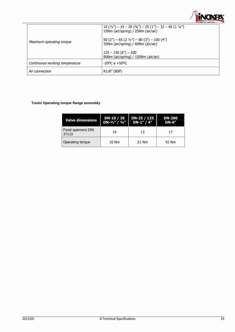
Maximum operating torque
10 (½”) – 15 – 20 (¾”) – 25 (1”) – 32 – 40 (1 ½”) 15Nm (air/spring) / 25Nm (air/air) 50 (2”) – 65 (2 ½”) – 80 (3”) – 100 (4”) 35Nm (air/spring) / 60Nm (air/air) 125 – 150 (6”) – 200 90Nm (air/spring) / 150Nm (air/air)
Continuous working temperatura -20ºC a +50ºC
Air connection R1/8” (BSP)
Tools/ Operating torque flange assembly
Valve dimensions DN-10 / 20
DN-½” / ¾” DN-25 / 125 DN-1” / 4”
DN-200 DN-6”
Fixed spanners DIN 37110
10 13 17
Operating torque 16 Nm 21 Nm 42 Nm

20 8.Technical Specifications 2013/05
8.2. MANUAL VALVE DIMENSIONS
DN d1 d7 A I H L DN d1 d7 A I H L
10 10 62 20 40 90 115 ½” 9,4 62 20 40 90 115
15 16 62 20 40 90 115 ¾” 15,8 62 20 40 90 115
20 20 72 20 40 95 115 1” 22,1 87 20 40 102 115
25 26 87 20 40 102 115 1 ½” 34,9 97 25 50 107 170
32 32 92 21 42 105 170 2” 47,6 110 25 50 115 170
40 38 97 25 50 107 170 2 ½” 60,3 118 25 50 125 170
50 50 110 25 50 115 170 3” 72,9 131 25 50 130 170
65 66 127 25 50 125 170 4” 97,4 162 30 60 150 170
80 81 142 30 60 130 170 6” * 146,8 240 66 132 180 300
100 100 162 30 60 150 170 8” * 197,6 284 75 150 205 325
125* 125 190 55 110 147 270
150* 150 240 66 132 180 300
200* 200 284 75 150 205 325
DN d1 D I f H L DN d1 D I f H L
25 26 93 68 40 90 150 1” 22,1 93 68 40 90 150
32 32 98 68 40 93 150 1 ½” 34,9 103 68 40 95 150
40 38 103 68 40 95 150 2” 47,6 115 72 40 100 150
50 50 115 72 40 100 150 2 ½” 60,3 117 72 40 110 150
65 66 132 72 40 110 150 3” 72,9 132 72 40 117 180
80 81 145 80 40 117 180 4” 97,4 165 80 40 128 180
100 100 165 80 40 128 180 6” * 146,8 240 140 90 180 300
125* 125 191 120 70 147 270
150* 150 240 140 90 180 300
S/S Fig.4800/40900
S/S Fig.4800/40900
*Only with two position handle
*Only with two position handle

2013/05 8.Technical Specifications 21
8.3. PNEUMATIC VALVE DIMENSIONS
DN d1 H
10 10 193 H1
15 16 193 H1
20 20 198 H1
25 26 207 H1
32 32 209 H1
40 38 212 H1
50 50 238 H2
65 66 247 H2
80 81 254 H2
100 100 264 H2
125 125 328 H3
150 150 352 H3
200 200 375 H3
½” 9,4 193 H1
¾” 15,8 198 H1
1” 22,1 207 H1
1 ½” 34,9 212 H1
2” 47,6 238 H2
2 ½” 60,3 239 H2
3” 72,9 247 H2
4” 97,4 264 H2
6” 146,8 352 H3

22 8.Technical Specifications 2013/05
8.4. PNEUMATIC VALVE DIMENSIONS AND C-TOP
T1
DN L1 H1
ST
AN
DA
RD
10-15—1/2” 213 338
20-3/4” 218 343
25-1” 227 352
32 229 354
40-11/2” 232 357
T2
DN L2 H2
25—1” 234 359
32 236 361
40-11/2” 239 364
ST
AN
DA
RD
50-2” 245 370
21/2” 146 271
65-3” 254 379
80 261 386
100-4” 271 396
T3
ST
AN
DA
RD
DN L3 H3
125 336 461
150-6” 360 485
200-8” 383 508
T1 T2
T3

NOTES

In addition to our branch offices, INOXPA operates with an independent distributor network which encompasses a total of more than 50 countries throughout the world. For more information, please, consult our web page: www.inoxpa.com
This information is for guidance only. We reserve the right to modify any material or feature without notice in advance.