installation p/n 08e83-mkc-a00 gl1800/d/da ... -...
TRANSCRIPT

Honda Dealer: Please give a copy of these instructions to your customer.
INSTALLATIONINSTRUCTIONS
Accessory Application
© 2018 American Honda Motor Co., Inc. - All Rights Reserved.
PARTS LIST
87961-MKC-A0001 of 12
Publication No.
MII 16426
Issue Date
January 2018
CB RADIOP/N 08E83-MKC-A00 GL1800/D/DA
(9)
No. Description Qty
(1) Installation Instructions URL 1
(2) CB main unit 1
(3) CB radio Owner’s Manual 1
(4) FCC rule book 1
(5) CB radio sub harness 1
(6) CB unit cover 1
(7) 5 mm screw 7
(8) O-ring 1
(9) Wire tie (long) 2
(10) Clip 2
(11) Clamp 1
(12) 4 mm screw 1
(5)
(1)
(6)
(2)
(3)
(8)
(10)
(11)
(4)
(7)
(12)
TOOLS AND SUPPLIES REQUIREDPhillips screwdriver
Hex wrench (5 mm)
Power drill
Drill bit (14 mm)
Hole saw (16 and 18 mm)
Dish soap solution (Water:Dish soap / 100:1)
Snips
Ruler
Scissors
Isopropyl alcohol
Shop towel
Torque wrench
CB ANTENNASold separately
(3)
(1)
(7)
(6)
(2)
(5)
(4)
No. Description Qty
(1) CB antenna 1
(2) CB antenna stay 1
(3) Wire tie (short) 2
(4) 6 mm socket bolt (short) 2
(5) 6 mm socket bolt (long) 1
(6) Cushion 1
(7) Installation Instructions URL 1
2 of 12
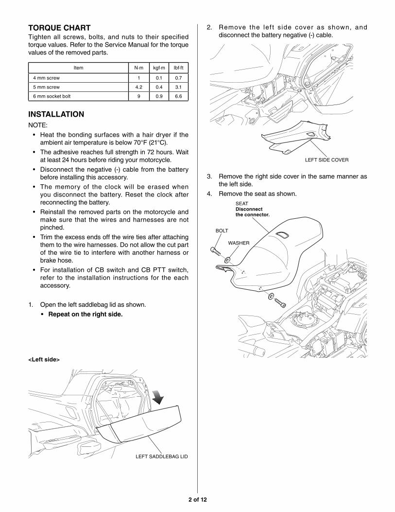
<Left side>
LEFT SADDLEBAG LID
2. Remove the lef t s ide cover as shown, and disconnect the battery negative (-) cable.
LEFT SIDE COVER
BOLT
WASHER
3. Remove the right side cover in the same manner as the left side.
4. Remove the seat as shown.
SEATDisconnect the connector.
INSTALLATIONNOTE:
• Heat the bonding surfaces with a hair dryer if the ambient air temperature is below 70°F (21°C).
• The adhesive reaches full strength in 72 hours. Wait at least 24 hours before riding your motorcycle.
• Disconnect the negative (-) cable from the battery before installing this accessory.
• The memory of the clock will be erased when you disconnect the battery. Reset the clock after reconnecting the battery.
• Reinstall the removed parts on the motorcycle and make sure that the wires and harnesses are not pinched.
• Trim the excess ends off the wire ties after attaching them to the wire harnesses. Do not allow the cut part of the wire tie to interfere with another harness or brake hose.
• For installation of CB switch and CB PTT switch, refer to the installation instructions for the each accessory.
1. Open the left saddlebag lid as shown.
• Repeat on the right side.
Item N·m kgf·m Ibf·ft
4 mm screw 1 0.1 0.7
5 mm screw 4.2 0.4 3.1
6 mm socket bolt 9 0.9 6.6
TORQUE CHARTTighten all screws, bolts, and nuts to their specified torque values. Refer to the Service Manual for the torque values of the removed parts.

3 of 12
REAR TRUNK LID
7. Remove the USB cord as shown.
• Perform this step on GL1800DA only.
USB CORD
6. Open the rear trunk lid as shown.
• If necessary, refer to the Owner’s Manual and use the emergency trunk cable to open the rear trunk lid.
9. Remove the trunk front lower panel as shown.
TRUNK FRONT LOWER PANEL
8. Remove the parts as shown.
<GL1800DA>
TRUNK HOLDER
SCREW
5. Remove the right and left passenger grips as shown.
WASHER
BOLT
RIGHT PASSENGER GRIP
CABLE
LEFT PASSENGER GRIPRemove the cable.

4 of 12
12. Remove the trunk right side cover as shown.
• Repeat on the left side.<Right side>
TRUNK RIGHT SIDE COVER
11. Remove the parts as shown.BOLT (Save)
WASHER (Save)
10. Remove the parts as shown.
• Repeat on the left side.SCREW
SCREW
CLIP
CLIP
14. Disconnect the connector and remove the center trunk lower cover as shown.
SCREW
CENTER TRUNK LOWER COVER
2-PIN WATERPROOF CONNECTOR (Black)
13. Remove the clips as shown.
• Repeat on the right side.
CLIP
<Left side>

5 of 12
17. Remove the right saddlebag upper cover as shown.
SCREW
SCREW
RIGHT SADDLEBAG UPPER COVERDisconnect the connector.
15. Remove the rear fender as shown.
SCREW
SCREW
REAR FENDERDisconnect the connector.
SADDLEBAG REAR CENTER COWL
16. Remove the saddlebag rear center cowl as shown.
18. Remove the plugs as shown.PLUG (Save)
PLUG (Save)
BOOTMove.
20. Clean the surface of the area shown with isopropyl alcohol.
ISOPROPYL ALCOHOL
19. Loosely install the wire tie as shown.
WIRE TIE (short)Loosely.
<Right side>
<Right saddlebag inside>

6 of 12
24. Install the clamp as shown.CLAMP
4 mm SCREW
23. Install the clips with the 5 mm screws as shown.
O-RING CB MAIN UNIT
5 mm SCREW
CLIP
22. Install the clips to the O-ring as shown.
O-RING
CB MAIN UNIT
CLIP
CLIP
21. Attach the CB main unit as shown.
CB MAIN UNITRemove the adhesive backing before attaching.

7 of 12
25. Remove the screws as shown.
27. Route the CB radio sub harness as shown.
26. Remove the 12P Black connector as shown.
SCREW
CB RADIO SUB HARNESS
CLIP
12-PIN WATERPROOF CONNECTOR (Black)
GROMMETInsert into the hole.
Move the right saddlebag catch and route the CB radio sub harness as shown.
29. Route the CB radio sub harness as shown.
CB RADIO SUB HARNESS
GROMMET
CB RADIO SUB HARNESS
RIGHT SADDLEBAG CATCH
28. Apply dish soap solution to the position shown.
DISH SOAP SOLUTIONApply.
8 of 12
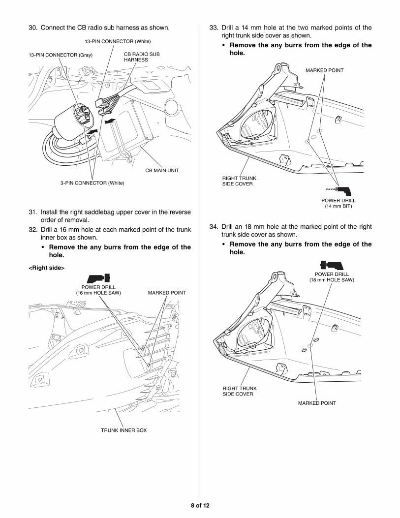
33. Drill a 14 mm hole at the two marked points of the right trunk side cover as shown.
• Remove the any burrs from the edge of the hole.
RIGHT TRUNK SIDE COVER
MARKED POINT
POWER DRILL (14 mm BIT)
34. Drill an 18 mm hole at the marked point of the right trunk side cover as shown.
• Remove the any burrs from the edge of the hole.
RIGHT TRUNK SIDE COVER
POWER DRILL(18 mm HOLE SAW)
30. Connect the CB radio sub harness as shown.
13-PIN CONNECTOR (White)
13-PIN CONNECTOR (Gray)
3-PIN CONNECTOR (White)
CB MAIN UNIT
CB RADIO SUB HARNESS
<Right side>
31. Install the right saddlebag upper cover in the reverse order of removal.
32. Drill a 16 mm hole at each marked point of the trunk inner box as shown.
• Remove the any burrs from the edge of the hole.
MARKED POINT
TRUNK INNER BOX
POWER DRILL(16 mm HOLE SAW)
MARKED POINT

9 of 12
Align the cushion and CB antenna cord with the marked line.
35. Clean the surface of the area shown with isopropyl alcohol.
RIGHT TRUNK SIDE COVER
ISOPROPYL ALCOHOL
36. Route the CB antenna cord as shown.
CB ANTENNA CORD
RIGHT TRUNK SIDE COVER
38. Attach the cut cushions as shown.
CB ANTENNA CORD
CB ANTENNA CORDMARKED LINE
MARKED LINE
RIGHT TRUNK SIDE COVER
CUT CUSHIONRemove the adhesive backing before attaching.
37. Cut the cushion to the dimensions shown.
30 mm 30 mm
SCISSORS
CUSHION
Not used.
CUT CUSHION
39. Route and secure the CB antenna cord, install the right trunk side cover in the reverse order of removal.
RIGHT TRUNK SIDE COVER
WIRE TIE (short)Secure the CB antenna cord to the motorcycle’s harness.
<Right side>
CB ANTENNA CORD
10 of 12
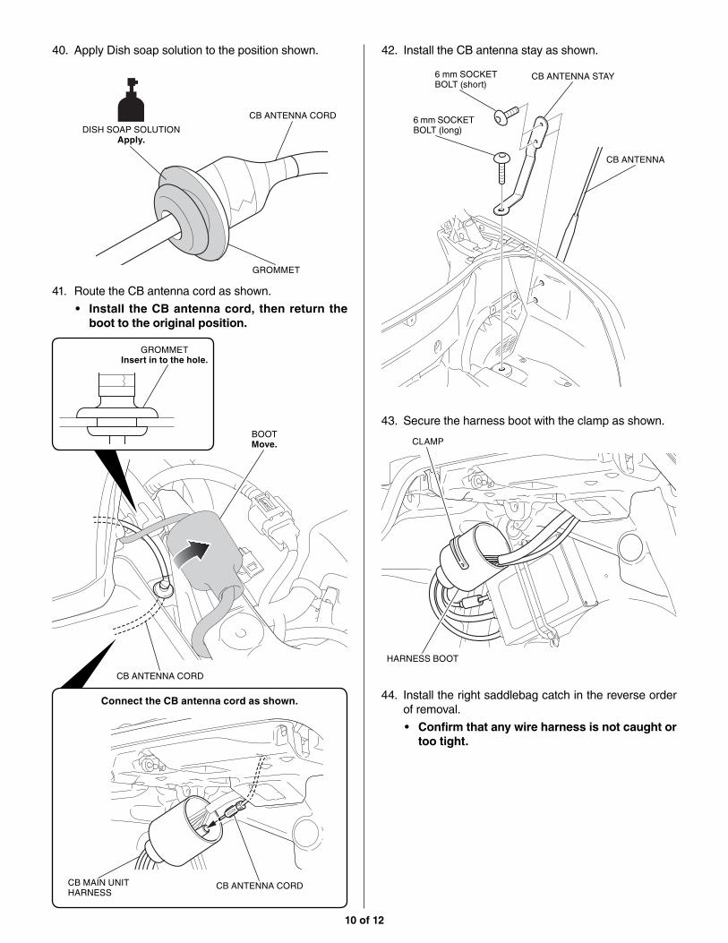
42. Install the CB antenna stay as shown.
6 mm SOCKET BOLT (long)
6 mm SOCKET BOLT (short)
CB ANTENNA STAY
CB ANTENNA
43. Secure the harness boot with the clamp as shown.
HARNESS BOOT
CLAMP
44. Install the right saddlebag catch in the reverse order of removal.
• Confirm that any wire harness is not caught or too tight.
40. Apply Dish soap solution to the position shown.
CB ANTENNA CORD
41. Route the CB antenna cord as shown.
• Install the CB antenna cord, then return the boot to the original position.
BOOTMove.
Connect the CB antenna cord as shown.
GROMMETInsert in to the hole.
GROMMET
CB ANTENNA CORD
CB ANTENNA CORDCB MAIN UNIT HARNESS
DISH SOAP SOLUTIONApply.

11 of 12
46. Move the boot and remove the dummy connector as shown.
47. Connect the CB radio sub harness as shown.
• Set the boot to the original position.
MOTORCYCLE’S HARNESS
BOOTMove.
MOTORCYCLE’S HARNESS
3-PIN WATERPROOF DUMMY CONNECTOR (Black) (Save)
CB RADIO SUB HARNESS
3-PIN WATERPROOF CONNECTOR (Black)
3-PIN WATERPROOF CONNECTOR (Black)
CB RADIO SUB HARNESS
45. Install the CB unit cover as shown.
• Confirm that any wire harness is not caught or too tight.
5 mm SCREW
CB UNIT COVER
48. Remove the dummy connector as shown.
26-PIN WATERPROOF DUMMY CONNECTOR (Black) (Save)
12 of 12
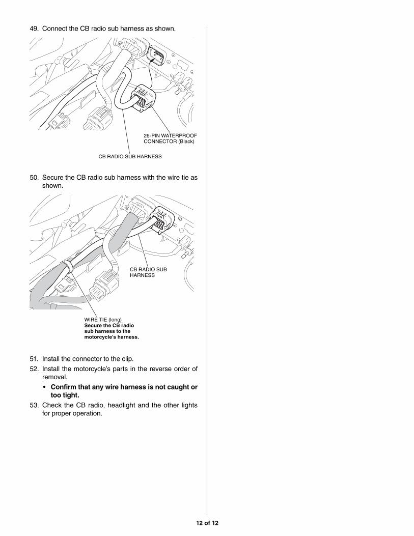
51. Install the connector to the clip.
52. Install the motorcycle’s parts in the reverse order of removal.
• Confirm that any wire harness is not caught or too tight.
53. Check the CB radio, headlight and the other lights for proper operation.
49. Connect the CB radio sub harness as shown.
50. Secure the CB radio sub harness with the wire tie as shown.
26-PIN WATERPROOF CONNECTOR (Black)
CB RADIO SUB HARNESS
CB RADIO SUB HARNESS
WIRE TIE (long)Secure the CB radio sub harness to the motorcycle’s harness.