installation & operation rigid rail safety system · pdf fileansi a14.3-2008 american...
TRANSCRIPT
© Copyright 2010, DB Industries, Inc.
A Capital Safety Company x1
1
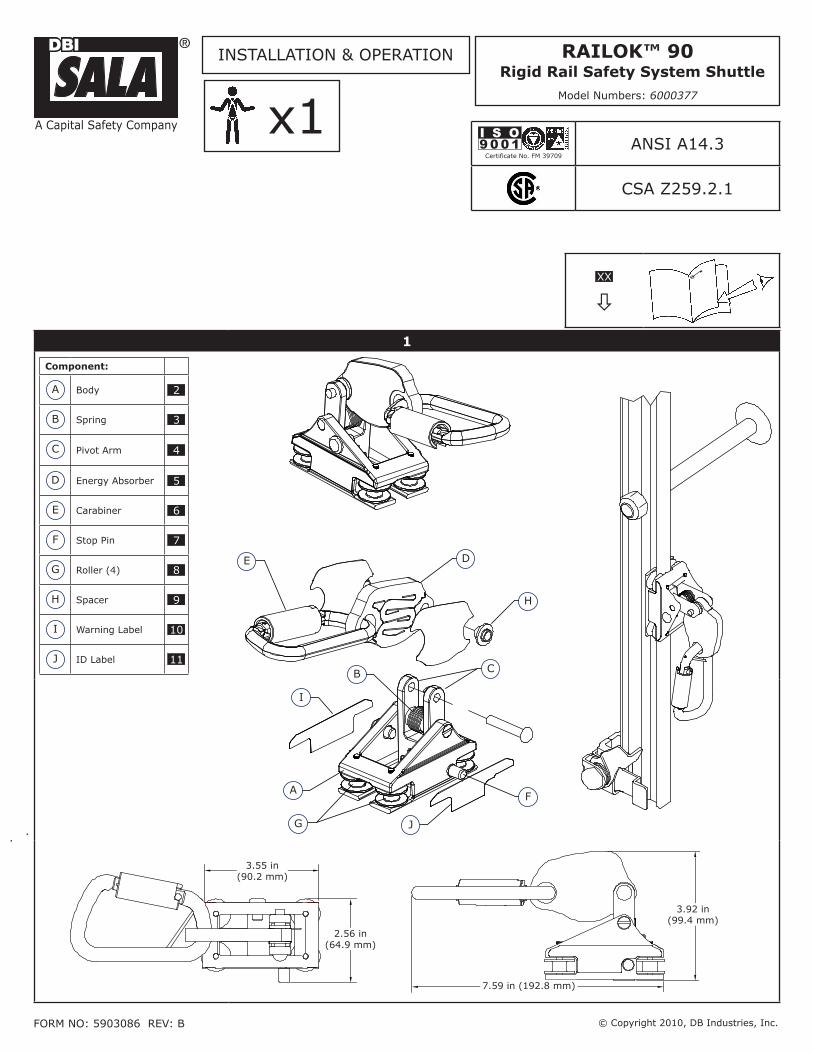
Component:
A Body 2
B Spring 3
C Pivot Arm 4
D Energy Absorber 5
E Carabiner 6
F Stop Pin 7
G Roller (4) 8
H Spacer 9
I Warning Label 10
J ID Label 11
E D
H
C
F
B
I
J
A
G
2.56 in(64.9 mm)
3.55 in(90.2 mm)
7.59 in (192.8 mm)
3.92 in(99.4 mm)
Certificate No. FM 39709
I S O9 0 0 1 ANSI A14.3
CSA Z259.2.1
XX
ò
INSTALLATION & OPERATION
FORm NO: 5903086 REv: B
Railok™ 90
Rigid Rail Safety System Shuttle
model Numbers: 6000377

2
A
3
A
B
4
A
B
5
A
6

3
FoRWaRD: This instruction describes installation and use of the Railok 90 Rigid Rail Safety System Shuttle. It should be used as part of an employee training program as required by OSHA.
IMportant: Before using this equipment, record the product identification information (Model Numbers, Serial Numbers, etc.) on the Inspection & Maintenance Log Table 2)
2
SpeCiFiC GloSSaRY ReFeReNCe BoXeS: Black Glossary Reference Boxes on the front cover of this instruction reference the following items:1 : Rigid Rail Safety System Shuttle 2 : Body 3 : Spring 4 : Pivot Arm 5 : Energy
Absorber 6 : Carabiner 7 : Stop Pin 8 : Roller 9 : Spacer 9 : Spacer 10: Warning Label 9 : ID Label
StaNDaRDS: Refer to local, state, and federal (OSHA) requirements governing occupational safety for additional information regarding Personal Fall Arrest Systems. Refer to the following national standards on fall protection:
ANSI Z359-0 Definitions and Nomenclature Used for Fall Protection and Fall Arrest
ANSI Z359-1 Safety Requirements for Personal Fall Arrest Systems, Subsystems, and Components
ANSI Z359-2 minimum Requirements for a Comprehensive managed Fall Protection Program
ANSI A14.3-2008 American National Standard for Ladders - Fixed - Safety Requirements
CSA Z259.2.1-98 Fall Arrestors, vertical Lifelines, and Rails
tRaiNiNG: It is the responsibility of users of this equipment to understand these instructions and be trained in correct installation, use, and maintenance of this equipment. Users must be aware of the consequences of improper installation or use of this equipment. This instruction manual is not a substitute for a training program. Training must be provided on a periodic basis to ensure user proficiency.
DeSCRiptioN: The Railok 90 Rigid Rail Safety System (Figure 1) provides fall protection for persons climbing fixed ladders or similar climbing structures. The Railok 90 Shuttle serves as a self-locking guided fall arrestor for a climber equipped with a Full Body Harness. The Shuttle travels along a Rigid Rail Safety System as the climber ascends or descends the ladder or similar structure. In the event of a fall the Shuttle locks onto the Rigid Rail to arrest the fall. The Shuttle is configured with a Shock Absorber to dissipate fall energy and limit fall forces transferred to the body.
puRpoSe: The Railok 90 Shuttle and Railok 90 Rigid Rail Safety System are components in a Personal Fall Arrest System (PFAS) for climbing ladders or similar structures where fall hazards exist. The PFAS would typically include a Full Body Harness, Anchorage Connector (e.g., Carabiner), Railok 90 Shuttle, and Railok 90 Rigid Rail Safety System.
SYStem RequiRemeNtS: Plan your fall protection system and how it will be used prior to installation. Consider all factors that will affect your safety before, during, and after a fall. Include the following considerations:
SYStem CapaCitY:• The Railok 90 Rigid Rail Safety System is designed to be used by 1-4 users averaging 250 lbs (113 kg). multiple users are required to climb sequentially so only a single user is on a rail span between consecutive mounting Brackets at any time.
StRuCtuRe:• The structure to which the Railok 90 Rigid Rail Safety System is installed must have a strength capable of sustaining static loads applied in the directions permitted by the system of at least:
Non-Certified Anchorages: 5,000 lbs (22.2 kN)
Certified Anchorages: 2 times the maximum Arresting Force
If there will be more than one user on the system, the above anchorage strengths should be multiplied by the number of people attached to the system.
Fall CleaRaNCe:• Fall clearance below the feet of the user to the ground or other surface must be at least 7 feet (2 m).
notE: For the bottom 7 feet (2 m) of the Railok 90 Rigid Rail Safety System, the user may not be protected against hitting the ground. Extra care should be taken when ascending or Descending the bottom section.
loCkiNG SpeeD:• Avoid using the Railok 90 Shuttle in situations where the climbing path is obstructed. Working in cramped spaces may not allow sufficient speed to lock the Shuttle when a fall occurs. A clear path is required to ensure positive locking of the system.
eNviRoNmeNtal HazaRDS:• Use of this equipment in areas with environmental hazards may require additional precautions to reduce the possibility of injury to the user or damage to the equipment. Hazards may include, but are not limited to: high heat caused by welding or metal cutting; caustic chemicals; seawater; high voltage power lines; explosive or toxic gases; moving machinery; sharp edges.
EN

4
CompoNeNt CompatiBilitY:• The Railok 90 Rigid Rail Safety System is designed for use with the Railok 90 Shuttle and a Full Body Harness (see Body Support). The use of non-approved components and subsystems may jeopardize compatibility of equipment, and could affect the safety and reliability of the complete system.
IMportant: The Railok 90 Rigid Rail Safety System should not be used in combination with another fall protection system or sub system, except if authorized by Capital Safety.
CompatiBilitY oF CoNNeCtoRS:• The only connector used with the Railok 90 Rigid Rail Safety System should be the Carabiner provided on the Railok 90 Shuttle or a replacements specified by Capital Safety.
BoDY SuppoRt:• A full body harness meeting the requirements of ANSI Z359.1 must be used with the Railok 90 Rigid Rail Safety System. The harness must have a frontal connection suitable for frontal fall arrest when ladder climbing (See Parts Table SH). The harness connection point must be above the users center of gravity. A body belt is not authorized for use with the Railok 90 system. If a fall occurs when using a body belt it may cause unintentional release and possible suffocation because of improper body support. Substitutions of equipment or system components must not be made without the written consent of Capital Safety.
Railok 90 SHuttle:• Only the Railok 90 Shuttle should be used as the mobile fall arrest component of the Railok 90 Rigid Rail Safety System. A Top Rail Gate (SRG-T/LRG-T) and Bottom Rail Gates (SRG-B or LRG-B) must be present to prevent the Shuttle from traveling off the ends of the Rail assembly. The distance between the Shuttle and the frontal connection on the Full Body Harness is limited by the Shuttle’s Energy Absorber and attached Carabiner. Never add additional Connectors or Lanyards that may increase this distance.
opeRatioN: General procedures for using the Railok 90 Shuttle are as follows:
IMportant: Before each use, carefully inspect the Railok 90 Rigid Rail Safety System per the steps described in the Inspection section.
Step 1. attaching the Railok 90 Shuttle on the Rigid Rail: The Railok 90 Shuttle (Figure 1) may be attached or removed from either the top or bottom of the rigid rail. The shuttle always moves freely upward. However, the pivot arm (C) must be lifted to allow downward movement. When the pivot arm is released, the spring (B) returns the pivot arm to its “locked” position and prevents the shuttle from moving downward. The stop pin (F) prevents the possibility of installing the Railok 90 Shuttle upside-down.
IMportant: The Railok 90 Shuttle should always be attached on the Railok 90 Rigid Rail with the arrows on the Warning Label (I) and ID Label (J) pointing up.
attaching from the Bottom of the Rail:a. Refer to Figure 2 for this procedure. Slide the shuttle upward from the bottom of the rail. The bottom rail gate (A) opens automatically and allows moving the shuttle to the working position.
Removing from the Bottom of the Rail:B. Refer to Figure 3 for this procedure. Slide the shuttle downward to the bottom rail gate. Push the rail gate lever (A), lift the pivot arm (B), and remove the shuttle from the rail.
attaching from the top of the Rail:C. Refer to Figure 4 for this procedure. Slide the shuttle downward from the top of the rail with the pivot arm (A) lifted. The top rail gate (B) opens automatically and allows moving the shuttle to the working position.
Removing from the top of the Rail:D. Refer to Figure 5 for this procedure. Slide the shuttle upward to the top rail gate. Push the top rail gate lever (A) and remove the shuttle from the rail.
Step 2. Connecting the Railok 90 Shuttle to the Full Body Harness: Connect the carabiner on the Railok 90 Shuttle to the Front Chest D-Ring on the Full Body Harness (see Figure 6). Always use the carabiner supplied on the Railok 90 Shuttle. Do not substitute with other connectors. Do not use other connecting devices such as a short lanyard, chain, link, or clevis. Connection between the Railok 90 Shuttle and the full body harness can be done before or after the Railok 90 Shuttle has been installed on the rail. When connecting, be sure the carabiner gate is fully closed and locked.
Step 3. ascending and Descending: Ascend and descend the climbing structure in the following manner:
ascendinga. : To ascend, climb up normally at a steady rate. The Railok 90 Shuttle will follow along smoothly.
DescendingB. : To descend, climb down smoothly in a normal position. If the Railok 90 Shuttle locks, move upward slightly to release the Railok 90 Shuttle and continue to descend.

5
iNSpeCtioN: To ensure safe, efficient operation, the Railok 90 Shuttle should be inspected at the following intervals:
Before each use: • visually inspect the Railok 90 Shuttle per the the Inspection Schedule (Table 1).
annually: • A formal inspection of the Railok 90 Shuttle and Rigid Rail Safety System must be performed at least annually by a competent person other than the user. See the Inspection Schedule (Table 1) for inspection procedures.
IMportant: Extreme working conditions (harsh environment, prolonged use, etc.) may require increasing the frequency of formal inspections.
after Fall arrest:• If the Railok 90 Shuttle has been subjected to a fall arrest or impact forces, it should be removed from service and inspected by a competent person other than the user.
table 1 - inspection Schedule
inspection: Refer to Figure 1 (front cover) for identification of referenced components. Before
each useannual
(Formal1)after a Fall
Inspect for loose screws and bent or damaged parts.1. X X X
Check the entire unit for signs of corrosion.2. X X X
Inspect the Railok 90 Shuttle body (A) for cracks or other damage.3. X X X
Ensure the Pivot Arm (C) rotates freely and is not damaged or distorted.4. X X X
Ensure5. the energy absorber (D) rotates smoothly on the pivot and has not been damaged (unfolded).
X X X
Ensure both ends of the torsion spring (B) are seated properly. One end 6. sits in the shuttle body (A), and the other end sits on the energy absorber spacer (H).
X X X
In climatic locations where ice formation is possible, inspect the Shuttle 7. for excessive ice that may impede performance. Clear Shuttle of ice as necessary.
X X X
All labels must be present and fully legible (see back pages)8. X X X1 Formal Inspection: A formal inspection must be performed at least annually by a competent person other than the user.
IMportant: Record the inspection results in the Inspection & Maintenance Log (Table 2).
IMportant: Extreme working conditions (harsh environment, prolongued use, etc.) may require increasing the frequency of inspections.
DeFeCtS: If inspection or operation reveals a defective condition, remove the component from service and contact an authorized service center for repair.
IMportant: Only Capital Safety, or parties authorized in writing, may make repairs to this equipment.
maiNteNaNCe & SeRviCe: Guidelines for maintaining and servicing the are as follows:
The Railok 90 Shuttle may be cleaned using commercial parts cleaning solvents and rinsed with warm, soapy • water. Light machine oil may be applied to moving parts if required. Do not use excessive oil or allow oil to contact rail clamping surfaces.
Additional maintenance and servicing procedures must be completed by an authorized service center. • Authorization and a return number must be issued by Capital Safety.
StoRaGe: Store the Railok 90™ Shuttle in a clean, dry, warm environment. Avoid areas where chemical vapors may exist. Thoroughly inspect the Shuttle after extended storage. Clean and store body support and associated system components according to the manufacturer’s instructions.

6
table 2 inspection and maintenance log
SERIAL NUMBER:
MODEL NUMBER:
DATE PURCHASED: DATE OF FIRST USE:
iNSpeCtioN Date iNSpeCtioN itemS NoteD
CoRReCtive aCtioN maiNteNaNCe peRFoRmeD
Approved By:
Approved By:
Approved By:
Approved By:
Approved By:
Approved By:
Approved By:
Approved By:
Approved By:
Approved By:
Approved By:
Approved By:
Approved By:
Approved By:
Approved By:
Approved By:
Approved By:
Approved By:

i
UP
HA
UT
AU
FA
LTO
UP
HA
UT
AU
FA
LTO
0086EN353-1:2002
X1MAXI.
AS/NZS18971.3
CSAZ259.2.1
CLASS: AS
ANSI A14.3-2008
PART NUMBER9505239 REV B LOT CODE WARNING Read and follow manufacturer’s instructions supplied with this product before use. Do not use with incompatible rails. Use only with DBI-SALA approved systems and harness. Maximum distance allowed between system cable and harness attachment before use. Make only compatible connections between sleeve and harness. Failure to heed warnings may result in serious injury or death. Veuillez lire et suivre les instructions du fabricant fournies avec ce produit avant toute utilisation. N’utilisez pas avec des rails incompatibles. Utilisez avec des harnais et des systèmes approuvés par DBI-SALA uniquement. La distance maximale autorisée entre le câble du système et le point de fixation du harnais est de 22,86 cm (9 po) [ANSI]. Procédez à une inspection avant toute utilisation et au moins une fois par an (CSA). N’utilisez que des connecteurs compatibles entre le manchon et le harnais. Ne pas tenir compte de ces avertissements peut entraîner de graves blessures, voire la mort. 9505240 REV B
AVERTISSEMENT

Certificate No. FM 39709
I S O9 0 0 1
A Capital Safety Company
CSG uSa & latin america3833 SALA Way Red Wing, mN 55066-5005 Toll Free: 800.328.6146Phone: 651.388.8282Fax: [email protected]
CSG Canada260 Export Boulevard mississauga, ON L5S 1Y9 Phone: 905.795.9333 Toll-Free: 800.387.7484 Fax: 888.387.7484 [email protected]
CSG Northern europeUnit 7 Christleton Courtmanor ParkRuncornCheshire, WA7 1ST Phone: + 44 (0)1928 571324Fax: + 44 (0)1928 [email protected]
CSG emea(europe, middle east, africa)Le Broc CenterZ.I. 1ère Avenue 5600m - B.P.15 06511 Carros le Broc CedexFrancePhone: + 33 4 97 10 00 10Fax: + 33 4 93 08 79 [email protected]
CSG australia & New zealand20 Fariola StreetSilverwaterSydney NSW 2128AUSTRALIAPhone: +(61) 2 9748 0335Toll-Free : 1 800 245 002 (AUS)Toll-Free : 0800 212 505 (NZ) Fax: +(61) 2 9748 0336 [email protected]
CSG asiaSingapore:16S, Enterprise Road Singapore 627666Phone: +65 - 65587758Fax: +65 - [email protected]
Shanghai:Rm 1406, China venturetech Plaza819 Nan Jing Xi Rd,Shanghai 200041, P R ChinaPhone: +86 21 62539050Fax: +86 21 62539060
www.capitalsafety.com
WaRRaNtY
Equipment offered by DBI-SALA is warranted against factory de-fects in workmanship and materials for a period of two years from date of installation or use by the owner, provided that this period shall not exceed two years from date of shipment. Upon notice in writing, DBI-SALA will promptly repair or replace all defective items. DBI-SALA reserves the right to elect to have any defective item returned to its plant for inspection before making a repair or replacement. This warranty does not cover equipment damages resulting from abuse, damage in transit, or other damage beyond the control of DBI-SALA. This warranty applies only to the original purchaser and is the only one applicable to our products, and is in lieu of all other warranties, expressed or implied.