installation & operation manual burger king flexible batch ... · tallatio operatio maual or...
TRANSCRIPT
Installation & Operation Manual CE Version
BURGER KINGFLEXIBLE BATCH BROILER
Please read this manual completely before attempting to install, operate or service this equipment
This manual is Copyright © 2013 Duke Manufacturing Co. All rights reserved. Reproduction without written permission is prohibited. Duke is a registered
trademark of the Duke Manufacturing Co.
Duke Manufacturing Co.2305 N. Broadway
St. Louis, MO 63102Phone: 314-231-1130
Toll Free: 1-800-735-3853Fax: 314-231-2460www.dukemfg.com
P/N 175820R

Installation & Operation Manual for Flexible Batch Broiler - CE Units
2
TABLE OF CONTENTSI. General Information .....................................................................................................4 A.BatchBroilerSpecifications ...................................................................................4 A-1. Model Number Key ......................................................................................4 A-2.BroilerDimensions ......................................................................................5II. Installation Instructions ..............................................................................................6 A.QualifiedPersonnel ................................................................................................6 B.DeliveryandInspection ..........................................................................................6 C.BroilerAssembly ....................................................................................................8 D.AdjustmentsatInstallation .....................................................................................9 RaiseorLowerBroiler ........................................................................................9 E.LocationoftheBroiler ..........................................................................................10 F.GasPiping ............................................................................................................10 G.ElectricalConnections .........................................................................................10 H.Ventilation ............................................................................................................10 VentingtoaCanopyExhaustHood ..................................................................10 MaintenanceofVentilationSystem ...................................................................10III. Operation Instructions ............................................................................................. 11 A.BroilerControls .................................................................................................... 11 B.CookingProduct .................................................................................................. 11 B-1.0LightingtheBroiler ................................................................................... 11 B-2.0 Cook Product ...........................................................................................12 B-3.0 Cook Cycle Complete ..............................................................................13 B-4.0FineCookingAdjustment .........................................................................13 B-5.0CancelaCookCycle ...............................................................................13 B-6.0CheckingtheBroilerTemperature ...........................................................13 B-7.0CheckingtheSetPointTemperature .......................................................13 B-8.0ShutdowntheBroiler ...............................................................................13 C.Cleaning ...............................................................................................................13 C-1.Four(4)HourCleaning ..............................................................................15 C-2.DailyCleaning ...........................................................................................16 C-3.WeeklyCleaning ........................................................................................18 C-4.MonthlyCleaning ......................................................................................21 D.Troubleshooting ...................................................................................................22IV. Service and Repair ...................................................................................................25V. Replacement Parts List .............................................................................................26VI. Wiring Schematic .....................................................................................................28

3
Installation & Operation Manual for Flexible Batch Broiler - CE Units
IMPORTANT WARNING AND SAFETY INFORMATION
POST IN A PROMINENT LOCATION instructions to be followed in the event the user smells gas. This information shall be obtained by consulting the local gas supplier.
FOR YOUR SAFETY:
Do not store or use gasoline or other flammable vapors or liquids in the vicinity of this or any other appliance.
: Improper installation, adjustment, alteration, service or maintenance can cause property damage, injury or death. Read the installation, operating and maintenance instructions thoroughly before installing or servicing this equipment.
THIS MANUAL MUST BE RETAINED FOR FUTURE REFERENCE.
Installation & Operation Manual for Flexible Batch Broiler - CE Units
4
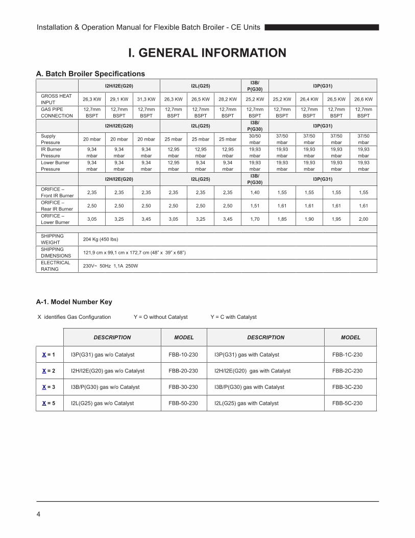
I. GENERAL INFORMATIONA. Batch Broiler Specifications
I2H/I2E(G20) I2L(G25) I3B/P(G30) I3P(G31)
GROSSHEATINPUT
26,3 KW 29,1 KW 31,3 KW 26,3 KW 26,5 KW 28,2 KW 25,2 KW 25,2 KW 26,4 KW 26,5 KW 26,6 KW
GASPIPECONNECTION
12,7mm BSPT
12,7mm BSPT
12,7mm BSPT
12,7mm BSPT
12,7mm BSPT
12,7mm BSPT
12,7mm BSPT
12,7mm BSPT
12,7mm BSPT
12,7mm BSPT
12,7mm BSPT
I2H/I2E(G20) I2L(G25) I3B/P(G30) I3P(G31)
Supply Pressure
20 mbar 20 mbar 20 mbar 25 mbar 25 mbar 25 mbar30/50 mbar
37/50 mbar
37/50 mbar
37/50 mbar
37/50 mbar
IRBurnerPressure
9,34 mbar
9,34 mbar
9,34 mbar
12,95 mbar
12,95 mbar
12,95 mbar
19,93 mbar
19,93 mbar
19,93 mbar
19,93 mbar
19,93 mbar
LowerBurnerPressure
9,34 mbar
9,34 mbar
9,34 mbar
12,95 mbar
9,34 mbar
9,34 mbar
19,93 mbar
19,93 mbar
19,93 mbar
19,93 mbar
19,93 mbar
I2H/I2E(G20) I2L(G25) I3B/P(G30) I3P(G31)
ORIFICE–FrontIRBurner
2,35 2,35 2,35 2,35 2,35 2,35 1,40 1,55 1,55 1,55 1,55
ORIFICE–RearIRBurner
2,50 2,50 2,50 2,50 2,50 2,50 1,51 1,61 1,61 1,61 1,61
ORIFICE–LowerBurner
3,05 3,25 3,45 3,05 3,25 3,45 1,70 1,85 1,90 1,95 2,00
SHIPPINGWEIGHT
204Kg(450lbs)
SHIPPINGDIMENSIONS
121,9cmx99,1cmx172,7cm(48”x39”x68”)
ELECTRICALRATING
230V~ 50Hz 1,1A 250W
A-1. Model Number Key
XidentifiesGasConfiguration Y=OwithoutCatalyst Y=CwithCatalyst
DESCRIPTION MODEL DESCRIPTION MODEL
X = 1 I3P(G31)gasw/oCatalyst FBB-10-230 I3P(G31)gaswithCatalyst FBB-1C-230
X = 2 I2H/I2E(G20)gasw/oCatalyst FBB-20-230 I2H/I2E(G20)gaswithCatalyst FBB-2C-230
X = 3 I3B/P(G30)gasw/oCatalyst FBB-30-230 I3B/P(G30)gaswithCatalyst FBB-3C-230
X = 5 I2L(G25)gasw/oCatalyst FBB-50-230 I2L(G25)gaswithCatalyst FBB-5C-230

5
Installation & Operation Manual for Flexible Batch Broiler - CE Units
21,68 1/2"
88,434 3/4"
100,339 1/2"
12850 3/8"
111,944"
52,920 3/4"
161,7
63 5/8"
136,153 5/8"
GAS CONNECTION3/4" BSPT FEMALE
115,845 5/8" 141,4
55 5/8"
HIGH POSITION LOW POSITION
A-2. Broiler Dimensions
Note: Dimensionshownincentimeters,bracketed[]areininches

Installation & Operation Manual for Flexible Batch Broiler - CE Units
6
A. QUALIFIED PERSONNEL
These installation instructions are for the use ofqualified installation and service personnel only. Installationorservicebyotherthanqualifiedpersonnelmayresultindamagetothebroilerand/orinjurytotheoperator.Qualifiedinstallationpersonnelarethoseindividuals,firms,companiesorcorporationswhicheitherinpersonorthroughanagentisengagedinandresponsiblefor:• Compliance with the installation in force
in the country in which the appliance is to beinstalled.
• This appliance shall be installed with sufficientventilationtopreventtheoccurrenceofunacceptableconcentrationsofsubstancesharmfultohealthintheroominwhichtheapplianceisinstalled.
• Caution - the appliance is mounted on 4wheels.Caremustbetakennottohitkitchenwallsorsimilarhardobjectswhilemovingorinstallingtheappliance.
• Parts protected by the manufacturer, agent, orassigneeshallnotbeadjustedbytheinstaller.
• Thisapplianceisnotintendedforusebypersons(includingchildren)withreducedphysical,sensoryormentalcapabilities,orlackofexperienceandknowledge,unlesstheyhavebeengivensupervisionorinstructionconcerninguseoftheappliancebyapersonresponsiblefortheirsafety.
B. DELIVERY AND INSPECTION
DukeManufacturingCo.doeseverythingwithinitspowerto insureyoureceivedyourbroiler ingoodcondition.Theyarestrappeddownonheavywoodenskidsandpackedtopreventshippingdamage.Theyhaveallbeencarefully inspected before they were packaged andconsignedtothecarrier.
Upon delivery of your Duke broiler:
• Lookovertheshippingcontainer,carefullynotinganyexteriordamageonthedeliveryreceipt,whichmustalsobesignedbythedriver/deliveryperson.
• Unpack and check for any damage, whichwasnotevidentontheoutsideoftheshippingcontainer.
Caution: The Broiler is very heavy! Use adequate help for lifting.
II. INSTALLATION INSTRUCTIONS

7
Installation & Operation Manual for Flexible Batch Broiler - CE Units
1. Using a utility knife, cut away plasticwrap (notshown).
2. Removethetopcardboardandinnercap.
3. RemoveTrainingMaterialbox.
4. Removecardboardfromthecorners(4places).
5. Removecardboardontheends(2places).
6. Removebandingstraps (cutwithutility knifeorscissors:5places).
7. Removeboxofattachablepartsandaccessoriesfromthefront.
8. Safelyliftoneendofbroilerandtapblocktowardscenterandthensidewaystoremove.
Repeatforremainingblocks.Thisallowscastersto touch the pallet.
9. Removethebroilerfromtheshippingpalletusing3peopletoguideanddistributeitsweight(approx335lbs)accordingly.Whilecarefullysupportingthebroiler,rollitforwarduntilthefrontcastersareclearofthepallet.Liftthebroiler6-8inchesaboveandawayfromthepallet,andgentlyplaceonfloortoavoiddamagetocasters.
10.Removeprotectivebluetapefrombroilerpanels,doublecheckingthatnotaperemains.
• Checkforconcealeddamage.Thecarriermustbenotifiedwithinfifteen(15)daysofthedeliveryofthebroilerandthecarton,skidandallpackagingmaterialsmustberetainedforinspection.
• DukeManufacturingCo.cannotassumeliabilityforlossordamagesufferedintransit.Thecarrierassumesfullresponsibilityfordeliveryingoodorderwhentheshipmentwasaccepted.However,wearepreparedtoassistyouwithfilingyourclaim.
2
3
5
4
6
7
4
4
5
8
Installation & Operation Manual for Flexible Batch Broiler - CE Units
8
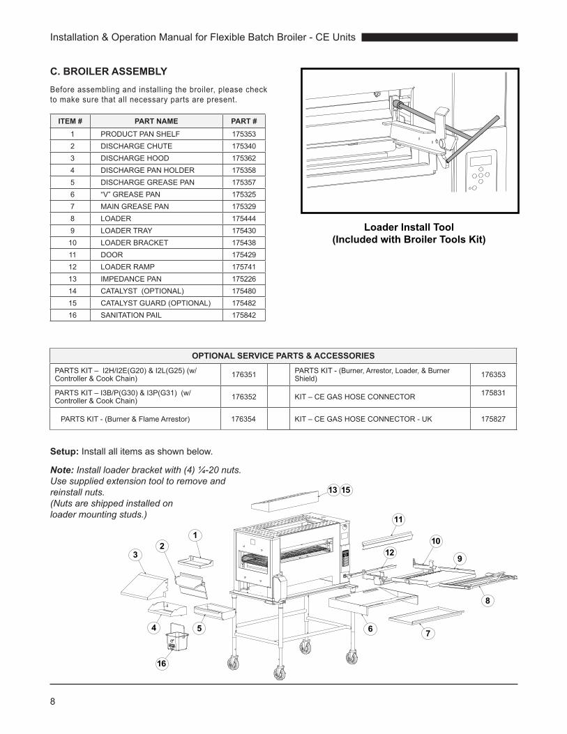
C. BROILER ASSEMBLYBeforeassemblingandinstallingthebroiler,pleasechecktomakesurethatallnecessarypartsarepresent.
ITEM # PART NAME PART #1 PRODUCTPANSHELF 1753532 DISCHARGECHUTE 1753403 DISCHARGEHOOD 1753624 DISCHARGEPANHOLDER 1753585 DISCHARGEGREASEPAN 1753576 “V”GREASEPAN 1753257 MAINGREASEPAN 1753298 LOADER 1754449 LOADERTRAY 175430
10 LOADERBRACKET 17543811 DOOR 17542912 LOADERRAMP 17574113 IMPEDANCEPAN 17522614 CATALYST(OPTIONAL) 17548015 CATALYSTGUARD(OPTIONAL) 17548216 SANITATIONPAIL 175842
Loader Install Tool (Included with Broiler Tools Kit)
12
13 15
11
10
9
8
7654
32
1
16
Setup: Installallitemsasshownbelow.
Note: Install loader bracket with (4) ¼-20 nuts. Use supplied extension tool to remove and reinstall nuts. (Nuts are shipped installed on loader mounting studs.)
OPTIONAL SERVICE PARTS & ACCESSORIESPARTSKIT–I2H/I2E(G20)&I2L(G25)(w/Controller&CookChain) 176351 PARTSKIT-(Burner,Arrestor,Loader,&Burner
Shield) 176353
PARTSKIT–I3B/P(G30)&I3P(G31) (w/Controller&CookChain) 176352 KIT–CEGASHOSECONNECTOR 175831
PARTSKIT-(Burner&FlameArrestor) 176354 KIT–CEGASHOSECONNECTOR-UK 175827

9
Installation & Operation Manual for Flexible Batch Broiler - CE Units
Thebroilerheightcanbeadjustedviatwoscrewsoneachleg.
Caution: The Broiler is very heavy! Use adequate help for lifting.
1. Liftoneendofthebroilerontoawide,sturdystand(notsupplied).
2. Remove (2) screws per leg and raise/lower tothreadedholes.Reinstallscrews.
3. Removestandandsafelyraise/lowerbroiler.
4. Placeplasticholeplugs(suppliedattachtostand)inanyunusedholes.
D. ADJUSTMENTS AT INSTALLATION
Eachbroilersectionandallitscomponentpartshavebeentestedthoroughlyandinspectedbeforeyourbroilerwasshippedfromthefactory.However,itissometimesnecessarytofurthertestoradjustthebroileronceithasbeeninstalled.SuchadjustmentsaretheresponsibilityoftheDealerorInstaller.Thesetypesofadjustmentsarenotconsidereddefects,ratheranormalandroutinepartoftheproperinstallationoftheequipment.
Theseadjustmentsincludebutarenotlimitedto:
•Adjustmentstothegaspressureregulator
•Broilerheightadjustment(ifrequired)
No installation should be considered completewithoutproper inspectionand, ifnecessary,anyadjustments by qualified service or installationpersonnel.
It isalso importantnot toobstruct thenatural flowofcombustionandventilationair if thebroiler is tooperateproperly.Thisbroilershouldnotbeinstalledonacurbbaseorsealedtothewall.Eitherconditioncanrestricttheflowofairtothecombustioncompartmentorpreventproperventilationoftheunit.Beforemakinganyconnectionstothebroiler,checktheratingsplatetobesurethebroilerspecificationsconcurwiththetypeofgasandvoltagetobesuppliedtothebroiler.
Theratingplateislocatedonthebackofthecontrolcompartmentcoverpanelontherightendoftheunit.
Theplatebearingthebroiler’smodelnumberandserialnumberisattachedtothebacksideoftheunit.
Raise or Lower Broiler
Support broiler here
Screw
Screw
Slide Leg. Reinstall screws.
Plastic Hole Plug

Installation & Operation Manual for Flexible Batch Broiler - CE Units
10
E. LOCATION OF THE BROILER
Properplacementofthebroilerwillgiveyouthebestresultslong-termuserconvenience.Weurgeyoutogiveadequatethoughtintheplacementofyourbroilerpriortoitsarrival.
• Thebroilershouldbeplacedinanareathatisfreefromdraftsandaccessibleforproperoperationandservicing.
• Theareaaroundthebroilermustbekeptclearofcombustiblematerialsasspecificbelow:
COMBUSTIBLE SURFACE SPACING
DischargeEnd(leftside) 305 mm
AccessPanelEnd(rightside) 76 mm
Rear 102 mm
Floor/Table 0 mm
F. GAS PIPING
The standard broiler consumes gas at a total of100,000 BTU/hr, 29.4 KW.Theoverallpipingplanof the kitchen must support the supply rating tosupportappliancetoachievetheperformancerating.
Generally, piping should be sized to provide a gassupplysufficienttomeetthemaximumdemandofallgasappliancesonalinewithoutunduelossofpressuretotheequipment.ThetotalBTUrequirementsofallequipmentbeingservedandthepipinglengthfromthemeteraremajorconsiderationsintheproperdesignofthegassupplysystem.
NOTE: A fixed restraint of the proper length must be incorporated to secure the broiler to a non-movable surface to eliminate strain on the gas connector.
G. ELECTRICAL CONNECTIONS
Yourbroilermustbesuppliedfroma230Volt50Hz,groundedcircuitwithasupplycordforeachcountry’srequirements.Awiringdiagramisattachedtothebroilercontrolcompartmentandwiththismanual.
The Main Supply safety / earth ground wire mustbe longer than main conductors at the unit'sinterconnectionstopreventstressunderpull.
Ifthesupplycordisdamaged,itmustbereplacedbythemanufacture,it'sserviceagentorsimilarlyqualifiedpersonsinordertoavoidahazard.
EXTERNAL EQUIPOTENTIAL
Terminal provides a connection for bonding toequipmentenclosure.
: This appliance employs an earthed, safety ground electrical supply system. DO NOT cut or modify the earthing provisions of this appliance.
H. VENTILATION
This appliance shall be installed with sufficientventilationtopreventtheoccurrenceofunacceptableconcentrationsofsubstancesharmfultohealthintheroominwhichtheapplianceisinstalled.
Venting to a Canopy Exhaust HoodAmechanically driven exhaust hood must have aminimumcapacityof1700m3/hr (1000cfm)withaminimum100cmby130cm(39.4inby51.2in)openingto adequately vent this appliance. The specifiedcapacityandopeningisrequiredinadedicatedhoodfor this appliance or in addition to other applianceventedthroughacommoncanopyexhausthood.
Maintenance of Ventilation SystemThe ventilation system must be maintained andannuallyinspectedbyQualifiedPersonnelconcurrentaspartoforinadditiontogovernmentalrequirements.
This inspection/maintenance should consist of, butnotbelimitedto:
• Inspectionforblockagesorbuildupwhichmightinterferewiththeventingofthebroiler.
• Repairofsuchblockages.
• Inspectionoftheventingcanopy,itsdrivemotorsandbells,etc.
: Do not place any objects such as sheet pans, food containers or aluminum foil on the top of the broiler. This will obstruct the venting of cooking vapors and airflow through the unit—resulting in poor cooking performance.

11
Installation & Operation Manual for Flexible Batch Broiler - CE Units
Theinformationinthissectionisintendedfortheuseofqualifiedoperatingpersonnel.QualifiedOperatingPersonnel are those individualswho have carefullyread the information contained in this manual, arefamiliarwiththefunctionofthebroilerand/orhavehadexperiencewithoperating theequipmentdescribed.Werecommendfollowingtheseinstructionstoinsureoptimumperformance,longlifeandtrouble-freeservicefromyourbroiler.
The controller is pre-programmed at the factory forknownrecipesatthetimeofmanufacture.Theproductkeysmustbeprogrammedwithanapprovedrecipeandthebroilerproperlycalibratedpriortouse.
A. Broiler Controls1. Power Switch –TurnsthebroilerONorOFF.The
broilerisself-lighting.
2. Product Selection Keys –Selects theproductrecipetorun.Alsofunctionsasnumberkeys1-8inprogrammingmode.
3. Arrow Keys
Up-Arrow: Displays the current broi lertemperaturewhenpressedinrunmode.Scrollsbackwardthroughparameterswhenpressedinprogrammode.
Down-Arrow: Displays the broiler set-pointtemperaturewhenpressedinrunmode.Scrollsbackward through parameterswhen pressed inprogrammode.
Left-Right Arrows:Movesbetweencharactersorparametersinprogrammode.Alsousedasnumerals0and9keys.
4. Display
5. Enter Key–Pressandholdfor5secondstoenterprogrammode.Alsousedtomovethoughandenterparametersinprogrammingmode.
6. Cook Light – Thislightislitduringpreheatandtheentirecook.Theoperatorshouldnotloadthebroilerwhilethelightislit.
DO NOTLOAD
IF LIGHT ON
1
2
3
4
6
5
B. Cooking Product
B-1.0 Lighting the Broiler
• Start Ventilation System.
• TurnON/OFFswitchtotheON(1)position.
• ThecontrolwilldisplayPrEduringthepre-heatcycle.
• TheLED'snexttoallproductkeyswithnon-zerocooktimeswillbered.
• ThecontrolwilldisplayrdYatthecompletionofthepre-heatcycleandtheLED’snexttoallproductkeyswithnon-zerocooktimeswillbegreen.
• (Toshutdownthebroiler,seesectionB-8.0)
III. OPERATION INSTRUCTIONS

Installation & Operation Manual for Flexible Batch Broiler - CE Units
12
B-2.0 Cook Product
DO NOTLOAD
IF LIGHT ON
Broiler displays rdY and Cook light is not on.
Place holding pan at discharge. Place product in front and back rows.
Load product. Push forward as shown.
Rotate handle down to lift inside bar over product.
Pull out loader with handle rotated.
Press appropriate product key.
Youwill have 15 seconds topressanotherproductkeyifawrongselectionismade.
The display will alternatelydisplay the time remainingandthefour-characterproductidentifier.
TheLEDnexttotheselectedproductkeywillflashred.
DO NOTLOAD
IF LIGHT ON
The cook light will be lit.

13
Installation & Operation Manual for Flexible Batch Broiler - CE Units
B-3.0 Cook Cycle CompleteThechainwillrotateanddischargetheproduct.
Do not load product into broiler until the cook light has gone off and rdY is displayed on the control!
To prevent thawing of product, it is recommended not to place product onto the loader no more than 5 minutes prior to loading.
B-4.0 Fine Cooking AdjustmentUsethisfunctiontoaddorsubtractupto30secondsfromaproductcookcyclerecipe.Thisshouldbeusedin theeventproductcookingneeds tobeoptimizedoutsideoftheprogrammingenvironment.Thisfunctionworksasfollows:
Press and hold the ▲and▼keysfor3seconds.
ThecontrolwilldisplayAdJ.
AllproductLED’sforproductswithaprogrammedtimewilllightred.
Selectaproductkeytoadjust.
TheselectedproductLEDwillremainredandallotherproductLED’swillgoblank.
Thecontrolwillflash AdJfollowedbytheproductidentifier.
The ▲and▼keys are used to set the fine cooking adjustment.
Thefirstpressofthe ▲or▼keybringsuptheadjustmentscreen.Thecontrolwilldisplaythetotalproductcooktimeincludingthepreviousfinecookingadjustment.
Subsequentpressesofa ▲or▼keyaddsorsubtracts1secondfromthecooktime.
Thecooktimecanbeincreasedordecreasedbyupto30secondswiththisfunction.
Toexit this functionandsave thesetting,press theENTERkey.
B-5.0 Cancel a Cook CyclePressingandholdingaproductkeyfor3secondswillcancelacookcycleanddischargetheproduct.
B-6.0 Checking the Broiler Temperature
Pressing the ▲ key at any time (other than inprogramming mode) will display the actual cavitytemperature.
B-7.0 Checking the Set Point TemperaturePressing the ▼ key at any time (other than inprogrammingmode)willdisplay theset-pointcavitytemperature.
B-8.0 Shutdown the BroilerTurn ON/OFF switch to the OFF (O) position.
C. CleaningTheexterior stainless steel on your broiler canbekeptcleanwithagoodnon-abrasivestainlesssteelcleaner,manyofwhichareonthemarket.MoistenaclothandwipedownthebroilerwhileitisCOLD.Wipingdownabroilerwhileitishotwillcausestreakingandotherwiseunsatisfactoryresults.Oncethebroileriscleanitcanbewipeddownwithlightoil.
Tohelpmakeyouruseofthisbroilertrouble-freeandtomaintainthewarranty,thefollowingrecommendationsmustbefollowed:
A. Donotexposethebroilertoprolongedcontactwith detergents, cleansers, bleaches, etc.Shield the IR burners and flame sensingrodsfromallcleaningfluids.DonotsprayIRburnerswithanyforeignmaterials.Chemicalcleaners, degreasers, bleaches and soapsolutionsmustneverbeallowedtocomeintocontactwiththeIRburnermetalhousingsorceramicburnertilesastheymaydamagethesesurfacesand/orcausebroilermalfunctionandwillvoid thewarranty.Topreventdamage totheceramicburnertiles,neverallowphysicalcontactwithcleaningtoolsorotherobjectsthatmayscratchormarthetilesurfacesorcauseblockageofthegasportsinthetilefaces.Donotsprayflamesensingrodswithanyforeignmaterials. Chemical cleaners, degreasersandsoapsolutionsmustneverbeallowedtocomeintocontactwiththeflamesensingrodsastheymaydamagethesesurfacesorcausebroilermalfunctionandwillvoidthewarranty.Ifrequired,cleantheflamesensingrodsonlyafterallowingtocoolofftoroomtemperature,and using a l ight wiping act ion with a pre-saturated alcohol pad to remove anycarbonbuildup.
B. Neverleavethechemicalcompounds,particularly
Installation & Operation Manual for Flexible Batch Broiler - CE Units
14
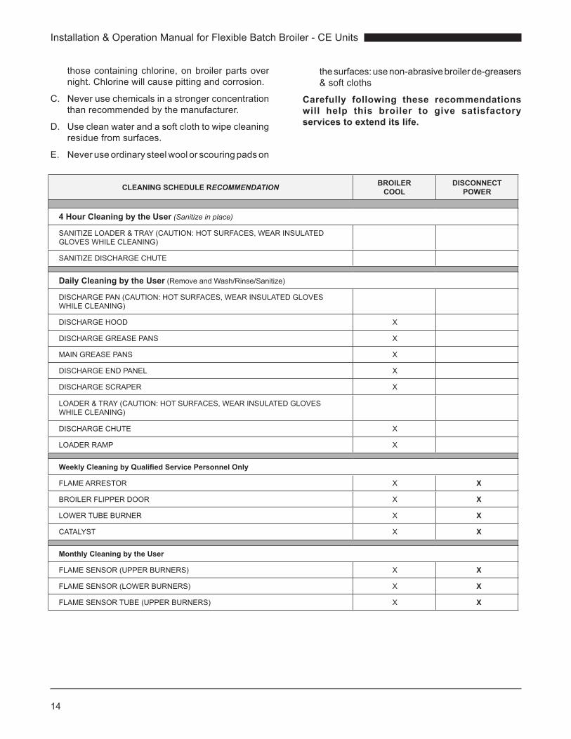
thosecontainingchlorine,onbroilerpartsovernight.Chlorinewillcausepittingandcorrosion.
C. Neverusechemicalsinastrongerconcentrationthanrecommendedbythemanufacturer.
D. Usecleanwaterandasoftclothtowipecleaningresiduefromsurfaces.
E. Neveruseordinarysteelwoolorscouringpadson
thesurfaces:usenon-abrasivebroilerde-greasers&softcloths
Carefully following these recommendations will help this broiler to give satisfactory services to extend its life.
CLEANING SCHEDULE RECOMMENDATION BROILER COOL
DISCONNECT POWER
4 Hour Cleaning by the User (Sanitize in place)
SANITIZELOADER&TRAY(CAUTION:HOTSURFACES,WEARINSULATEDGLOVESWHILECLEANING)
SANITIZEDISCHARGECHUTE
Daily Cleaning by the User (RemoveandWash/Rinse/Sanitize)
DISCHARGEPAN(CAUTION:HOTSURFACES,WEARINSULATEDGLOVESWHILECLEANING)
DISCHARGEHOOD X
DISCHARGEGREASEPANS X
MAINGREASEPANS X
DISCHARGEENDPANEL X
DISCHARGESCRAPER X
LOADER&TRAY(CAUTION:HOTSURFACES,WEARINSULATEDGLOVESWHILECLEANING)
DISCHARGECHUTE X
LOADERRAMP X
Weekly Cleaning by Qualified Service Personnel Only
FLAMEARRESTOR X X
BROILERFLIPPERDOOR X X
LOWERTUBEBURNER X X
CATALYST X X
Monthly Cleaning by the User
FLAMESENSOR(UPPERBURNERS) X X
FLAMESENSOR(LOWERBURNERS) X X
FLAMESENSORTUBE(UPPERBURNERS) X X

15
Installation & Operation Manual for Flexible Batch Broiler - CE Units
C-1. Four (4) Hour CleaningAllcomponentsthatareincontactwithfoodproductmustbecleanedandsanitizedevery4hours.
Loader and Carriage: Remove loader fromcarriageandsanitize foodcontactareas.
Caution: Hot surface near door! Wear insulated gloves.
Discharge Chute: Withdischargehoodremoved,sanitizeoutsidechutesurface.
Caution: Hot surface! Wear insulated gloves.

Installation & Operation Manual for Flexible Batch Broiler - CE Units
16
C-2. Daily CleaningDailycleaningshouldalsoincludeall itemslistedinthe4hourcleaningschedule.
1
2
2
1
Discharge Hood and Chute: Removehoodandchutecompletely,cleanandreplace.
D i s c h a r g e P a n : Slide pan up andout of keyhole slots. Cleanandreplace.
Engage hooks on pins for reinstallation of chute
Discharge Grease Pan: Tilt up to un-hook andpull forward for removal.Cleanpan,areaandreplace.
Be sure to tilt up and push all the way back during re-installation!
Grease Pans:Removetop“V”panandlowercollectionpan.Cleanbothpans,areaandreplace.
Caution: Very Hot! Wait for pan to cool before removal.

17
Installation & Operation Manual for Flexible Batch Broiler - CE Units
C-2. Daily Cleaning (cont’d)
Clean the top of the burner with the brush end of the “Tube
Burner Cleaning Tool”.
For heavy build-up, use the scraper end of the “Tube Burner
Cleaning Tool”.
Use the end of the tool to clean the discharge shaft of
the conveyor.
With the broiler cool, lift and remove the flipper door.
Clean and set aside.
1
2
Lift and slide retaining bolt right.
12
Lift slightly and remove loader ramp as shown.
Disengage pin from pivot hole. Clean and set aside.
Discharge End Panel: Remove discharge accessories and lift panel up while swinging
out and down.
Discharge Scraper: Lift up and pull forward.
Discharge Scraper: Pull out removing locating pins from slots. Clean scraper and
area. Replace.
Installation & Operation Manual for Flexible Batch Broiler - CE Units
18
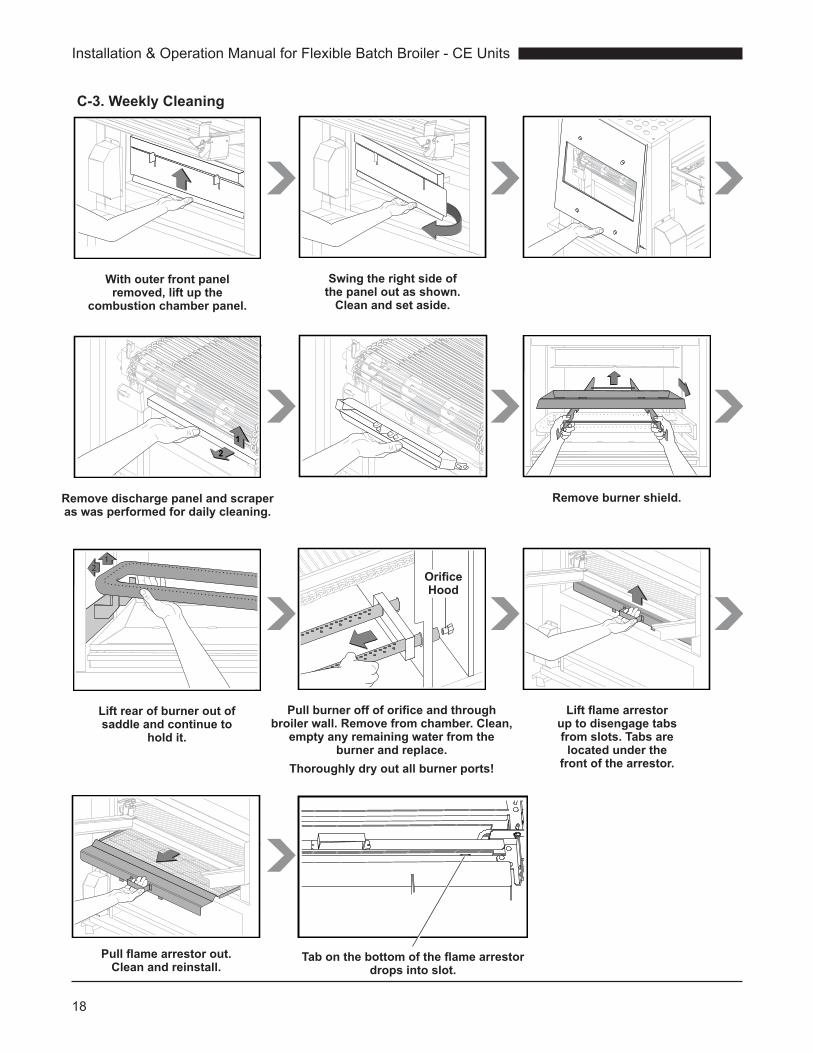
C-3. Weekly Cleaning
With outer front panel removed, lift up the
combustion chamber panel.
Swing the right side of the panel out as shown.
Clean and set aside.
21
Remove discharge panel and scraper as was performed for daily cleaning.
Remove burner shield.
12
Lift rear of burner out of saddle and continue to
hold it.
Orifice Hood
Pull burner off of orifice and through broiler wall. Remove from chamber. Clean,
empty any remaining water from the burner and replace.
Thoroughly dry out all burner ports!
Lift flame arrestor up to disengage tabs from slots. Tabs are located under the
front of the arrestor.
Pull flame arrestor out. Clean and reinstall.
Tab on the bottom of the flame arrestor drops into slot.
19
Installation & Operation Manual for Flexible Batch Broiler - CE Units
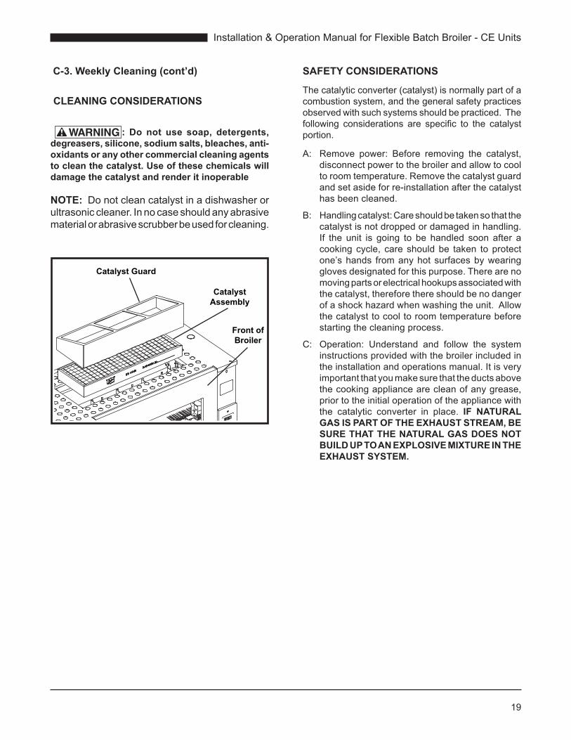
Catalyst Guard
Catalyst Assembly
Front of Broiler
C-3. Weekly Cleaning (cont’d)
CLEANING CONSIDERATIONS
: Do not use soap, detergents, degreasers, silicone, sodium salts, bleaches, anti-oxidants or any other commercial cleaning agents to clean the catalyst. Use of these chemicals will damage the catalyst and render it inoperable
NOTE: Donotcleancatalystinadishwasherorultrasoniccleaner.Innocaseshouldanyabrasivematerialorabrasivescrubberbeusedforcleaning.
SAFETY CONSIDERATIONS
Thecatalyticconverter(catalyst)isnormallypartofacombustionsystem,andthegeneralsafetypracticesobservedwithsuchsystemsshouldbepracticed.Thefollowing considerations are specific to the catalystportion.
A: Remove power: Before removing the catalyst,disconnectpowertothebroilerandallowtocooltoroomtemperature.Removethecatalystguardandsetasideforre-installationafterthecatalysthasbeencleaned.
B: Handlingcatalyst:Careshouldbetakensothatthecatalystisnotdroppedordamagedinhandling.If the unit is going to be handled soon after acookingcycle, care shouldbe taken toprotectone’shands fromanyhotsurfacesbywearingglovesdesignatedforthispurpose.Therearenomovingpartsorelectricalhookupsassociatedwiththecatalyst,thereforethereshouldbenodangerofashockhazardwhenwashingtheunit.Allowthecatalysttocooltoroomtemperaturebeforestartingthecleaningprocess.
C: Operation: Understand and follow the systeminstructionsprovidedwiththebroilerincludedintheinstallationandoperationsmanual.Itisveryimportantthatyoumakesurethattheductsabovethecookingappliancearecleanofanygrease,priortotheinitialoperationoftheappliancewiththe catalytic converter in place. IF NATURAL GAS IS PART OF THE EXHAUST STREAM, BE SURE THAT THE NATURAL GAS DOES NOT BUILD UP TO AN EXPLOSIVE MIXTURE IN THE EXHAUST SYSTEM.
Installation & Operation Manual for Flexible Batch Broiler - CE Units
20
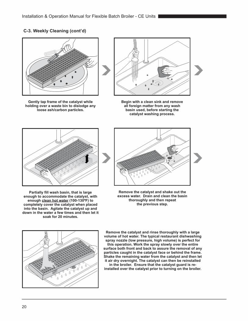
C-3. Weekly Cleaning (cont’d)
Gently tap frame of the catalyst while holding over a waste bin to dislodge any
loose ash/carbon particles.
Begin with a clean sink and remove all foreign matter from any wash basin used, before starting the
catalyst washing process.
Partially fill wash basin, that is large enough to accommodate the catalyst, with
enough clean hot water (100-130ºF) to completely cover the catalyst when placed into the basin. Agitate the catalyst up and
down in the water a few times and then let it soak for 20 minutes.
Remove the catalyst and shake out the excess water. Drain and clean the basin
thoroughly and then repeat the previous step.
Remove the catalyst and rinse thoroughly with a large volume of hot water. The typical restaurant dishwashing spray nozzle (low pressure, high volume) is perfect for this operation. Work the spray slowly over the entire
surface both front and back to assure the removal of any particles caught in the catalyst face or behind the frame. Shake the remaining water from the catalyst and then let it air dry overnight. The catalyst can then be reinstalled
in the broiler. Ensure that the catalyst guard is re-installed over the catalyst prior to turning on the broiler.

21
Installation & Operation Manual for Flexible Batch Broiler - CE Units
C-4. Monthly Cleaning
Locate the flame sensors for the upper burners.
Use caution and safely remove the sensor by holding onto the black
boot at the base of the sensor.
DO NOT REMOVE BY PULLING ON THE BRAIDED WIRE.
Retaining Clip
Using an alcohol swab, clean the entire metal portion of the sensor rod to remove any buildup. Clean
the white ceramic insulator using the alcohol swab until all residue has been
removed.Remove the back panel of the broiler and carefully remove
the sensor for the lower burner. Follow the same procedures as
those for the upper burners.
After the sensor is removed, use the T-handled cleaning tool by inserting it completely into the sensor tubes and remove.
Repeat the process at least five (5) times to remove any residue
inside the tube.
Once the cleaning procedures are complete, replace the sensors and panels. Wait at least 30 minutes before starting the broiler.
DO NOTLOAD
IF LIGHT ON
12
Remove top panel by lifting up and out.

Installation & Operation Manual for Flexible Batch Broiler - CE Units
22
D. TROUBLESHOOTING
SYMPTOM CAUSE REMEDY
Controldisplaydoesnotlightup Nopower Ensurebroilerispluggedintoapropervoltage/Hzreceptacle(pernameplaterating)andreceptacleaspower.Checkdedicated circuit breaker.
Raworundercookedproductwithnocontrollererrormessagesdisplayed.
Productnotloadedproperly. Reviewloadingtechnique.
Productbuttonwasdepressedpriortoloadingproduct.
Ensureproductbuttonisdepressedimmediatelyafterproductisloadedintobroiler.
Wrongproductbuttonwasdepressed. Ensureproperproductbuttonisbeingdepressed.
Lowerburnernotlightingproperly. (Observebottomburnerthroughslitsinlowergreasetray)
Ifbroilerishot,attempttocleanburnerinplacewithbroilercleaningtool.
Ifbroileriscoldorallowedtocooldown,removelowerburnerbyremovingaccesspanels,clean,andreinstall.Removelowerflamesensorandcleanwithasoftcloth&isopropylalcohol.
Infraredburnersnotlightingproperly.(ObserveInfraredthroughdischargeendofbroiler.Note:Burnersshouldremainlitinidle mode
Removeuppercontrolcompartmentpanelandclean2upperflamesensorswithasoftcloth&isopropylalcohol.
Cleanflamesensortubewithflamesensingtubecleaningbrush.
Conveyorbeltwillnotmovetodischargeproduct.
Conveyorbeltisbeingobstructed Observeforobstructionsbymanuallyrotatingconveyorbeltfromdischargeendofbroilerusingbroilercleaningtool.
Ensuredischargescraperisproperlyinplace.
Ensuredockingplateisproperlyinplace.
Ensureflamearrestorisproperlyinplace.
Loaderisnotabletobepushedcompletelyintocookingchamber
Dockingplateisnotproperlyinplace.
Ensuredockingplateandlockingtabarecorrectlyinplace.
Productisgettingstuckormangleduponloading
Dockingplateisnotproperlyinplace Ensuredockingplateandlockingtabarecorrectlyinplace.
Flamearrestorisnotproperlyinplace Ensureflamearrestoriscorrectlyinplaceandtabsareslottedcorrectly.

23
Installation & Operation Manual for Flexible Batch Broiler - CE Units
SYMPTOM CAUSE REMEDY
Controldisplayisreading“Hi” ContactDukeManufacturingCo.oraDukeAuthorizedServiceagent.
Controldisplayisreading“Lo” Lowerburnernotlightingproperly.(Observebottomburnerthroughslitsinlowergreasetray)
Ifbroilerishot,attempttocleanburnerinplacewithbroilercleaningtool.
Ifbroileriscoldorallowedtocooldown,removelowerburnerbyremovingaccesspanels,clean,andreinstall.Removelowerflamesensorandcleanwithasoftcloth&isopropylalcohol.
Infraredburnersnotlightingproperly.(ObserveInfraredthroughdischargeendofbroiler.Note:Burnersshouldremainlitinidlemode)
Removeuppercontrolcompartmentpanelandclean2upperflamesensorswithasoftcloth&isopropylalcohol.
Cleanflamesensortubewithflamesensingtubecleaningbrush.
Greasepanisnotinstalled Installgreasepan
Impedancepanorcatalystisnotinstalled. Installimpedancepanorcatalyst
Controldisplayisreading“Prob” ContactDukeManufacturingCo.oraDukeAuthorizedServiceagent.
ControlDisplayisreading“tESt Prod”
Lowerburnernotlightingproperly.(Observebottomburnerthroughslitsinlowergreasetray)
Ifbroilerishot,attempttocleanburnerinplacewithbroilercleaningtool.
Ifbroileriscoldorallowedtocooldown,removelowerburnerbyremovingaccesspanels,clean,andreinstall.Removelowerflamesensorandcleanwithasoftcloth&isopropylalcohol.
Infraredburnersnotlightingproperly.(ObserveInfraredthroughdischargeendofbroiler.Note:Burnersshouldremainlitinidlemode)
Removeuppercontrolcompartmentpanelandclean2upperflamesensorswithasoftcloth&isopropylalcohol. Cleanflamesensortubewithflamesensingtubecleaningbrush.
Installation & Operation Manual for Flexible Batch Broiler - CE Units
24
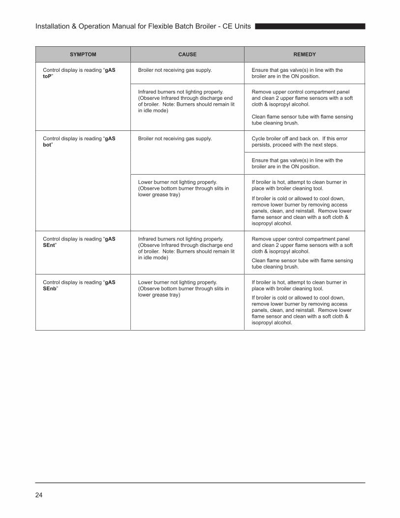
SYMPTOM CAUSE REMEDY
Controldisplayisreading“gAS toP”
Broilernotreceivinggassupply. Ensurethatgasvalve(s)inlinewiththebroilerareintheONposition.
Infraredburnersnotlightingproperly.(ObserveInfraredthroughdischargeendofbroiler.Note:Burnersshouldremainlitinidlemode)
Removeuppercontrolcompartmentpanelandclean2upperflamesensorswithasoftcloth&isopropylalcohol. Cleanflamesensortubewithflamesensingtubecleaningbrush.
Controldisplayisreading“gAS bot”
Broilernotreceivinggassupply. Cyclebroileroffandbackon.Ifthiserrorpersists,proceedwiththenextsteps.
Ensurethatgasvalve(s)inlinewiththebroilerareintheONposition.
Lowerburnernotlightingproperly.(Observebottomburnerthroughslitsinlowergreasetray)
Ifbroilerishot,attempttocleanburnerinplacewithbroilercleaningtool.
Ifbroileriscoldorallowedtocooldown,removelowerburnerbyremovingaccesspanels,clean,andreinstall.Removelowerflamesensorandcleanwithasoftcloth&isopropylalcohol.
Controldisplayisreading“gAS SEnt”
Infraredburnersnotlightingproperly.(ObserveInfraredthroughdischargeendofbroiler.Note:Burnersshouldremainlitinidlemode)
Removeuppercontrolcompartmentpanelandclean2upperflamesensorswithasoftcloth&isopropylalcohol.
Cleanflamesensortubewithflamesensingtubecleaningbrush.
Controldisplayisreading“gAS SEnb”
Lowerburnernotlightingproperly.(Observebottomburnerthroughslitsinlowergreasetray)
Ifbroilerishot,attempttocleanburnerinplacewithbroilercleaningtool.
Ifbroileriscoldorallowedtocooldown,removelowerburnerbyremovingaccesspanels,clean,andreinstall.Removelowerflamesensorandcleanwithasoftcloth&isopropylalcohol.
25
Installation & Operation Manual for Flexible Batch Broiler - CE Units
Periodicserviceandmaintenanceofthebroilerisnotrequiredbeyondtheuser’sdailyandweeklycleaningschedule defined in Sections C-1 to C-4. Qualifiedservice personnel must perform service or repairshouldthebroilerdevelopafaultotherthancleaningmaintenance.
Qualified service personnel are individuals, firms,companies,orcorporationswhoareknowledgeablein and responsible for compliance with jurisdictionauthorities concerning service of commercial foodpreparationequipment.ContacttheDukeManufacturingCompanyServiceDepartmentattheUSAworldwideheadquarters (telephone: 011-800-735-3853) forassistancewithselectingqualifiedservicepersonnel.
WARNINGStoqualifiedservicepersonnel:
: Disconnect the power supply to the appliance before servicing.
: Units provided with casters have a restraint to limit the movement that must be reconnected after servicing and installed in the original position.
: Proper clearances must be maintained during servicing and when installed in the original position.
IV. SERVICE AND REPAIR

Installation & Operation Manual for Flexible Batch Broiler - CE Units
26
V. REPLACEMENT PARTS LISTPartsthatwilllikelyrequirereplacementduringthelifeofthebroilerareidentifiedwitha“ ”intheReplacementPartsList.The“ ”symbolinthelistidentifiespartsthatareprotectedandshallnotbeorcannotbeadjustedbytheuser.Partsidentifiedwitha“-”shouldnotrequireadjustmentorreplacementduringthebroilerlife,butarelistedtoassistqualifiedservicepersonnelifreplacementisnecessary.
P/N DESCRIPTION
175503 SWITCH,LIGHTED,DPST -
175780 BURNER,INFRARED ,
176350 KIT,BURNER,ADJUSTABLE ,
175875 MOTOR-CONVEYOR -
175517 SPROCKET,B21X3/8BORE(MOTOR)
175037 SHAFT,DISCHARGESIDE
175038 SHAFT,RIGHTSIDE
175802 CAPACITOR,MOTOR-CONVEYOR
175876 MODULEIGNITION(7-5-3)CE(PROPANE,LOWERBURNERONLY)
175877 MODULEIGNITION(24-5-3)CE ,
175765 TRANSFORMER,40VA,230VAC-24VAC
175977 PROBE,TEMP.,C-CHAMBER
175550 LIGHT,COOK -
175870 RELAY-SOLIDSTATE ,
175551 CHAIN,DRIVE
175918 CONTROLLER
175510 GASKET,CONTROLBEZEL -
175511 GASKET,BLOWERINLET -
176186 BLOWER,230V50HZW/CENTRIFUGALSWITCH ,
175189 HOSE,BLOWER ,
175542 ORIFICEHOLDER,IR -
175182 KIT,VALVECEWITH90°FITTING ,
175935 ORIFICE,3.26mm,LOWERBURNER(I2H/I2E(G20),I2L(G25))
176388 ORIFICE,2.00mm,LOWERBURNER(I3P(G31))
175952 ORIFICE,1.70mm,LOWERBURNER(I3B/P(G30))
175814 ORIFICE,IRFRONT,2.35mm,GI2H/I2E(G20)&I2L(G25)
175815 ORIFICE,IRREAR,2.50mm,GI2H/I2E(G20)&I2L(G25)
175816 ORIFICE,IRFRONT,1.55mm,I3P(G31)
175817 ORIFICE,IRREAR,1.61mm,I3P(G31)
175818 ORIFICE,IRFRONT,1.40mm,I3B/P(G30)
175819 ORIFICE,IRREAR,1.51mm,I3B/P(G30)
176368 ORIFICEHOLDER3/8COMP.STRGHTXBULKHEAD
175476 TUBING-TEETOIR,KIT
175477 TUBING-TEETOVALVE,KIT
175178 TUBING-LOWERVALVETOORIFICEKIT

27
Installation & Operation Manual for Flexible Batch Broiler - CE Units
P/N DESCRIPTION
175534 SENSOR-LOWERBURNER ,
175535 SENSOR-IRBURNER ,
175536 IGNITER ,
175537 IGNITIONSUPPRESSIONCABLE-IR -
175538 IGNITIONSUPPRESSIONCABLE-LOWER -
175674 CHAIN,COOK ,
175525 BUSHINGBLOCK,CONVEYOR ,
175430 LOADERTRAY -
175438 LOADERMOUNTINGBRACKET -
175444 LOADER -
175741 LOADERRAMP -
175429 DOOR -
175293 FLAMEARRESTOR ,
176349 BURNERSHIELD ,
175340 DISCHARGECHUTE -
175778 DISCHARGEHOOD -
175363 PRODUCTPANSHELF -
175358 DISCHARGEPAN -
175329 MAINGREASEPAN -
175325 “V”GREASEPAN -
175357 SIDE,GREASEPAN -
175150 PIVOTASHSCRAPER -
175305 REARPANEL -
175300 FRONTPANEL -
175392 PANEL,UPPER,LIFTOFF -
175383 PANEL,ACCESSELECTRICALLWB -
175250 PANEL,ACCESSDISCHARGE -
175226 IMPEDANCEPAN(IFNOOPTIONALCATALYST) ,
175480 CATALYST(OPTIONAL) -
175482 CATALYST,GUARD -
175485 TUBEBURNERCLEANINGTOOL ,
175701 FLAMERODTUBECLEANER ,
175705 BRUSH,FLAMERODTUBECLEANER ,
175184 RELAY,10A,24VAC ,

Installation & Operation Manual for Flexible Batch Broiler - CE Units
28
VI. WIRING SCHEMATIC
T1L1+ S
olid
stat
e R
elay
T1L1+ So
lidst
ate
Rel
ay
PRIMARY
SECONDARY
PRIMARY
SECONDARY
Sens
or –
Rea
r IR
Bur
ner
Igni
ter –
Fron
t IR
Bur
ner
Igni
te –
Rea
r IR
Bur
ner
ON/OFF Switch
Sens
or –
Fron
t IR
Bur
ner
Capacitor 4uF
Con
veyo
r Mot
or
Sens
or –
Low
er B
urne
r
Igni
ter –
Low
er B
urne
r
1 2
1 2
2 1 1 2
1 2
1 1
3 2 1
Igni
tion
Xfm
r.
J 6J 5
J 4 J 3
BLK 11
WHT 11BLU 11
BRN 11
BRN 12
BRN 13
BRN 14
BLU 11
BLU 15
BLU 13
BRN 13
BLK
BLK
GR
N/Y
EL
BRN 12
BLU 12
BRN
15
RED
15
RED 15
BLU 14
BLKBL
K
BLK
BRN
ORG
BLK
BR
NO
RG
BLUBLU
BLU
BLU
BLU
7
OR
G 7
OR
G 6
GRN 4
GRN 0GRN 3
GRN 8GRN 2
GRN 7
GRN 9
GRN 1
BLK 6
BLK 5
BLU 7
BRN 8
RED 2
YEL 1
ORG 4
BLU 6
ORG 6
OR
G 8
YEL 1
RED 5
RED
3
RE
D 3
WHT 8
RED 4
GRN 7
GR
N 2
GR
N 1
GR
N 9
WH
T 8
BLU
4
BLU
4GR
N 8
GR
N 3
J1 & J 2 View
BLU
6
Power Cord Inlet
☼
24V
Con
trolle
r Xf
mr 24V
Relay –Conveyor Motor
BLK 11 WHT 11
BLU 11BRN 11
ON/OFF Switch Connections(Note: Indicator light Brn11 to Blu11)
ORG 8
BRN 8
2 1
2 1
+
Gas Valve – IR Burners
BLU
4GR
N 8
Gas Valve –Lower Burner
OR
G 7
GR
N 8
BLU
4
WH
T 8
RE
D 4
GRN 4
S1V
2 G
ND
V1TH
FC-
FC+S
1V2 G
ND
V1TH
FC-
FC+S1
V2 G
ND
V1
TH
FC-
FC+
Thermocouple
1
2
3
4
5
6
7
8
9
10
11
12
1
2
3
4
5
6
7
8
9
2 1
3 2 1
J 1
J 2
Con
trolle
r PC
Boa
rd
Load Light
Note: Warranty is voided when water sensitive stickers have changed color to red.
ELECTRICAL SCHEMATIC – CE FLEXIBLE BATCH BROILERDUKE MFG. 175806 Rev.E
BLU
5
ORG 5ORG 4
1 2
1 2
BLK 14
BLU 15
IR Blower Motorw/Centrifugal
Switch
DPST Relay
12
34
5
32
45
1
DPST Relay
ORG 3
RED
RED
OR
G
OR
G
BLU 5
BLU 101 BLU 102
RED 103
RED 104
RED 102
RED 2
N.O.
N.C.
N.O.
N.C.
ORG 5
RED 5
Igni
tion
Con
trol M
odul
eLo
wer
Bur
ner
Igni
tion
Con
trol M
odul
eFr
ont I
R B
urne
r
Igni
tion
Con
trol M
odul
eR
ear I
R B
urne
r

29
Installation & Operation Manual for Flexible Batch Broiler - CE Units
NOTES:

Installation & Operation Manual for Flexible Batch Broiler - CE Units
30
NOTES:

31
Installation & Operation Manual for Flexible Batch Broiler - CE Units
NOTES:
Installation & Operation Manual for Flexible Batch Broiler - CE Units
32
Duke Manufacturing Co.2305 N. Broadway
St. Louis, MO 63102Phone: 314-231-1130
Toll Free: 1-800-735-3853Fax: 314-231-5074
www.dukemfg.com