installation, operation & maintenance - viridian solar · (ii) install pipe from the solar...
TRANSCRIPT
viridians o l a r
R
podInstallation,Operation & Maintenance
Pod-PV, Pod-ST
v1.180030
1
pod
viridians o l a r
R
1
2
4
5
3
14
115
16
17
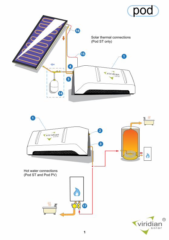
Solar thermal connections(Pod ST only)
Hot water connections(Pod ST and Pod PV)
2
Clearline
viridians o l a r
R
pod
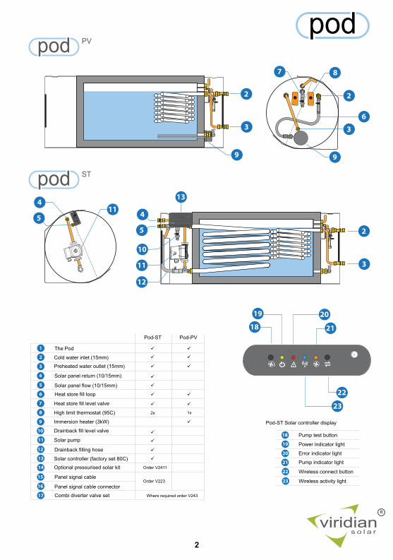
The Pod
Cold water inlet (15mm)
Solar panel return (10/15mm)
Solar panel flow (10/15mm)
Immersion heater (3kW)
High limit thermostat (95C)
Heat store fill level valve
Preheated water outlet (15mm)
Solar pump
Drainback fill level valve
Heat store fill loop
Drainback filling hose
Solar controller (factory set 80C)
Panel signal cable
Panel signal cable connector
Optional pressurised solar kit
Combi diverter valve set
Pod-ST
2x
Order V2411
Where required order V243
Pod-PV
Error indicator light
Power indicator light
Pump test button
Wireless connect button
Pump indicator light
Wireless activity light
Pod-ST Solar controller display
Order V223
1x
87
9
13
10
63
2
3
2
2
3
4
5
4
5
9
12
11
18
19
22
20
21
23
11
1
2
4
5
6
7
8
3
11
9
10
12
13
15
16
17
14
18
23
19 20
22
21
pod PV
pod ST

Operation
3
viridians o l a r
R
podContents
User Guide
Installation 1. Positioning the Pod 2. Connecting to the hot water system 3. Filling the Pod cylinder 4. Pod PV electric solar heating 5. Pod ST solar thermal heating 5a. Drainback solar system 5b. Pressurised solar system 5c. Insulating the solar pipes
Maintenance
Specifications
Commissioning Checklist
Maintenance Record
4
568899
1113
14
15
16
17

4
Operation
viridians o l a r
R
podAbout Solar Water Heating
SolarHeating Panels
UseThe Pod operates automatically, with minimal maintenance required (page 14).
or
SolarPV
Panels
Combi boilerHot WaterCylinder or
Energy for heating
Preheated water out
Cold water in
The Pod
The Pod saves you money and helps the environment by converting the light hitting a solar panel into hot water which reduces energy bills for water heating.
Pod ST is heated by solar heating panels. The solar heating panel absorbs light and traps the heat generated behind its cover glass. A liquid is pumped through the solar panel which carries the collected heat to the Pod. An electronic controller inside the Pod decides when to turn on the pump based on the temperature difference between the solar panel and the Pod.
Pod PV is heated by an electric immersion heater. A PV switch (not supplied) is used to divert electricity to the heater when the photovoltaic system is generating more electricity than the property is using.
5
Installation
viridians o l a r
R
pod
500
500kg
160
60
viridians o l a r
1250
+/-10mm
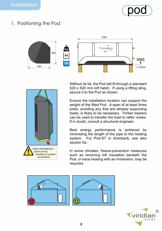
Without its lid, the Pod will fit through a standard 520 x 520 mm loft hatch. If using a lifting sling, secure it to the Pod as shown.
Ensure the installation location can support the weight of the filled Pod. A span of at least three joists, avoiding any that are already supporting loads, is likely to be necessary. Timber bearers can be used to transfer the load to rafter nodes. If in doubt, consult a structural engineer.
Best energy performance is achieved by minimising the length of the pipe to the heating system. For Pod-ST in drainback, see also section 5a.
In some climates, freeze-prevention measures such as removing loft insulation beneath the Pod, or trace heating with an immersion, may be required.
Leave packaging in place during
handling to protect connections
1. Positioning the Pod

6
Installation pod
viridians o l a r
R
>0
For a vented hot water cylinder, connect from the header tank to the cold water inlet (2) and from the preheated water outlet (3) to the cylinder cold inlet. The water level of the header tank must be higher than the Pod cold water inlet. In some circumstances it may be necessary to raise the header tank further or add a shower pump to maintain hot water flow rates. Insulate pipes in unheated areas and between Pod and cylinder.
For an unvented hot water cylinder, connect from the inlet control set to the Pod cold water inlet (2) and from the preheated water outlet (3) to the cylinder cold inlet. Insulate pipes in unheated areas and between Pod and cylinder.
2. Connecting to the Hot Water System
2a. Vented Hot Water Cylinder
2b. Unvented Hot Water Cylinder
7
Installation pod
viridians o l a r
R
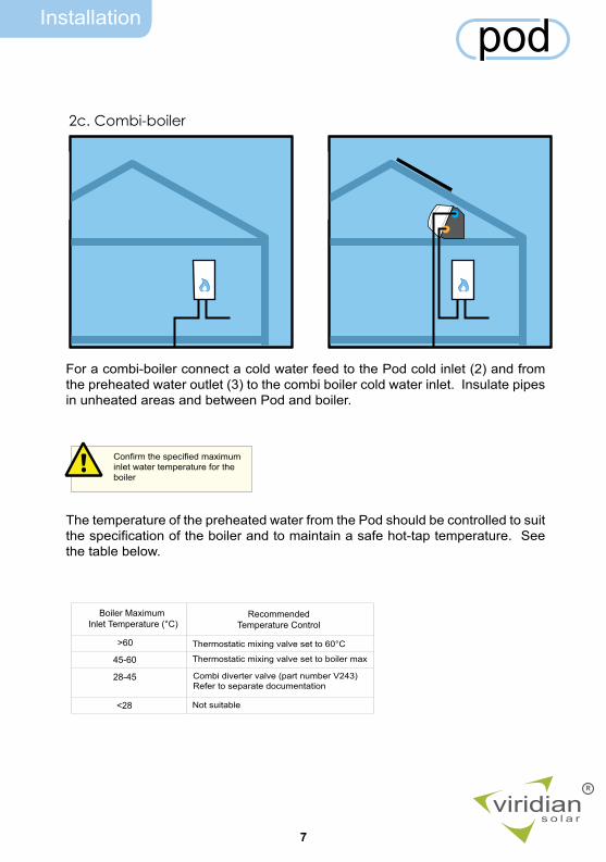
Boiler Maximum Inlet Temperature (°C)
45-60
28-45
>60
<28
Thermostatic mixing valve set to 60°C
RecommendedTemperature Control
Thermostatic mixing valve set to boiler max
Combi diverter valve (part number V243)Refer to separate documentation
Not suitable
For a combi-boiler connect a cold water feed to the Pod cold inlet (2) and from the preheated water outlet (3) to the combi boiler cold water inlet. Insulate pipes in unheated areas and between Pod and boiler.
Confirm the specified maximum inlet water temperature for the boiler
The temperature of the preheated water from the Pod should be controlled to suit the specification of the boiler and to maintain a safe hot-tap temperature. See the table below.
2c. Combi-boiler
8
Installation
viridians o l a r
R
pod7
6
9
8
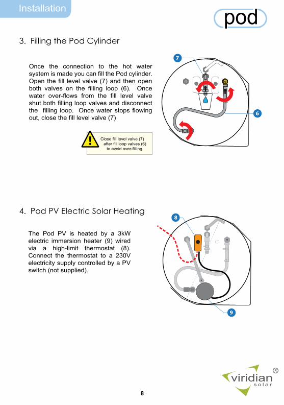
Once the connection to the hot water system is made you can fill the Pod cylinder. Open the fill level valve (7) and then open both valves on the filling loop (6). Once water over-flows from the fill level valve shut both filling loop valves and disconnect the filling loop. Once water stops flowing out, close the fill level valve (7)
3. Filling the Pod Cylinder
The Pod PV is heated by a 3kW electric immersion heater (9) wired via a high-limit thermostat (8). Connect the thermostat to a 230V electricity supply controlled by a PV switch (not supplied).
4. Pod PV Electric Solar Heating
Close fill level valve (7) after fill loop valves (6)
to avoid over-filling
9
Installation
viridians o l a r
R
pod
h
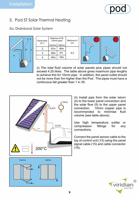
Panel Area
(m )2
2
3
4
B
A
Maximum A+B(10mm pipe) Maximum h
(m)
57m
48m
40m
5.0
10mm
200°C
(ii) Install pipe from the solar return (4) to the lower panel connection and the solar flow (5) to the upper panel connection. 10mm copper pipe is recommended to minimise fluid volume (see table above).
Use high temperature solder or compression fittings for any connections.
Connect the panel sensor cable to the top of control unit (13) using the panel signal cable (15) and cable connector (16).
46m
N/A
19m
Clearline Highline
CLICK
CLICK
Clearline Highline
5. Pod ST Solar Thermal Heating
5a. Drainback Solar System
(i) The total fluid volume of solar panels plus pipes should not exceed 4.25 litres. The table above gives maximum pipe lengths to achieve this for 10mm pipe. In addition, the panel outlet should not be more than 5m higher than the Pod. The pipes must have a continuous fall greater than 1 in 30.
10
Installation
viridians o l a r
R
pod
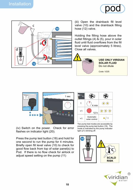
USE ONLY VIRIDIAN SOLAR FLUIDDo not dilute
Code: V225
Clearline
a
b
c
d
12
10
10
(iii) Open the drainback fill level valve (10) and the drainback filling hose (12) valve.
Holding the filling hose above the outlet fittings (4) & (5), pour in solar fluid until fluid overflows from the fill level valve (approximately 5 litres). Close all valves.
1
+1
+1
4 min
12 h
Automatic solar control
1 sec
(iv) Switch on the power. Check for error flashes on indicator light (20).
Press the pump test button (18) and hold for one second to run the pump for 4 minutes. Briefly open fill level valve (10) to check for good flow back from top of solar panel(s) to Pod. If there is no flow check for airlock or adjust speed setting on the pump (11)
Two pump test modes are accessible by pressing the pump test button (18). The mode is indicated by the pump indicator light (21) blinking off.
SCALD RISK
˚C
11
Installation
viridians o l a r
R
pod
CLICK
CLICK
15mm
200°C
14b
14a14c
Clearline Highline
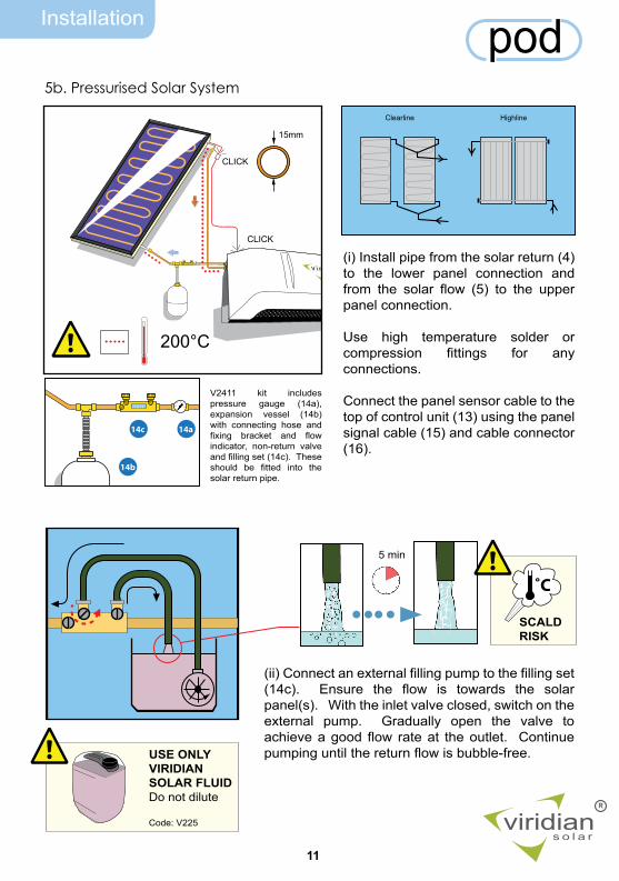
5b. Pressurised Solar System
(i) Install pipe from the solar return (4) to the lower panel connection and from the solar flow (5) to the upper panel connection.
Use high temperature solder or compression fittings for any connections.
Connect the panel sensor cable to the top of control unit (13) using the panel signal cable (15) and cable connector (16).
V2411 kit includes pressure gauge (14a), expansion vessel (14b) with connecting hose and fixing bracket and flow indicator, non-return valve and filling set (14c). These should be fitted into the solar return pipe.
(ii) Connect an external filling pump to the filling set (14c). Ensure the flow is towards the solar panel(s). With the inlet valve closed, switch on the external pump. Gradually open the valve to achieve a good flow rate at the outlet. Continue pumping until the return flow is bubble-free.
5 min
USE ONLY VIRIDIAN SOLAR FLUIDDo not dilute
Code: V225
SCALD RISK
˚C
12
Installation
viridians o l a r
R
pod
3.1 bar
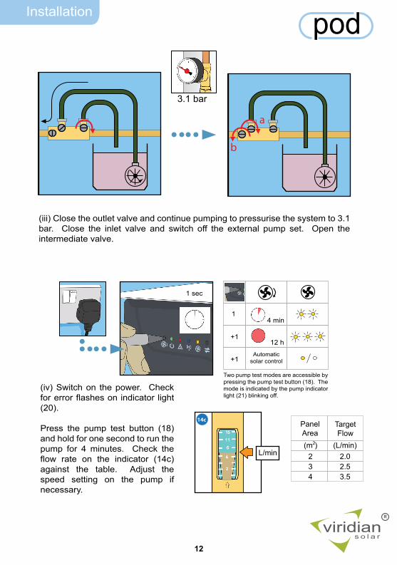
Panel Area(m ) (L/min)
2 2.03 2.54 3.5
Target Flow
2
L/min
14c
a
b
(iii) Close the outlet valve and continue pumping to pressurise the system to 3.1 bar. Close the inlet valve and switch off the external pump set. Open the intermediate valve.
1
+1
+1
4 min
12 h
Automatic solar control
1 sec
(iv) Switch on the power. Check for error flashes on indicator light (20).
Press the pump test button (18) and hold for one second to run the pump for 4 minutes. Check the flow rate on the indicator (14c) against the table. Adjust the speed setting on the pump if necessary.
Two pump test modes are accessible by pressing the pump test button (18). The mode is indicated by the pump indicator light (21) blinking off.
Installation
13
viridians o l a r
R
pod
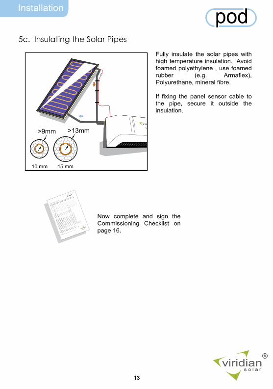
>9mm >13mm
10 mm 15 mm
Fully insulate the solar pipes with high temperature insulation. Avoid foamed polyethylene , use foamed rubber (e.g. Armaflex), Polyurethane, mineral fibre.
If fixing the panel sensor cable to the pipe, secure it outside the insulation.
Now complete and sign the Commissioning Checklist on page 16.
5c. Insulating the Solar Pipes
Maintenance
14
viridians o l a r
R
podMaintenanceWith regular simple maintenance, your Viridian Solar water heating system should provide years of trouble-free operation. It is not necessary to clean the solar panel, the action of rain will keep it clear.
Annual : Service AAll models: Inspect the pipe work and insulation for leaks or damage. Top up the Pod cylinder by reconnecting the filling loop (6) and following installation step 3 on page 8.
Pod ST Drainback: Check for error messages. Press the pump test button, and check for flow. See installation step 5a.(iv), page 10. If there is no flow follow installation step 5a.(iii).
Pod ST Pressurised. Check for error messages. Press the pump test button, and check for flow. See installation step 5b.(iv), page 12. Check the pressure indicator (14c) which should indicate a pressure close to the set pressure noted in the commissioning record (page 16) or around 3 bar. If pressure is low, or in the case of no flow, recharge following installation steps 5b.(ii) to (iv) on page 11-12.
Every 5 Years : Service BAs for Service A plus solar system fluid replacement (Pod ST only).
Pod ST Drainback. Switch off the power and drain the solar system from the filling hose (12) by opening the fill level valve (10) and the filling hose valve. Follow installation steps 5a.(iii) to (iv), page 10.
Pod ST Pressurised. Switch off the power and drain the solar system. Follow installation steps 5b.(ii) to (iv), page 11.
Use only system fluid from Viridian Solar (Product Code V225). Failure to use correct system fluid will invalidate your warranty and put the system at risk of freeze damage and corrosion.
Dispose of the system fluid at your local waste disposal centre. Propylene Glycol Solution.
Maintenance
15
viridians o l a r
R
pod
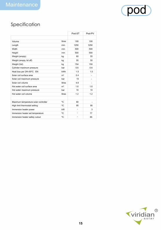
Pod-ST Pod-PV
Volume
Length
litres
mm
100 100
1250 1250
Width mm 500 500
Height mm 500 500
Weight (empty) kg 60 55
Weight (empty, lid off) kg 55 50
Weight (full) kg 154 150
Solar coil surface area m2 0.4 -
Solar coil maximum pressure bar 10 -
Solar coil volume litres 4.6 -
Hot water coil surface area m2 1.6 1.6
Hot water maximum pressure bar 10 10
Hot water coil volume litres 1.2 1.2
Cylinder maximum pressure bar 0.6 0.6
Heat loss per 24h 65ºC EN kWh 1.5 1.5
Hot water coil pressure loss at xlitres/min bar xx xx
Maximum temperature solar controller ºC 80 -
High limit thermostat setting ºC 95 95
Immersion heater power kW - 3
Immersion heater set temperature ºC - 77
Immersion heater safety cutout ºC - 85
Specification
Records
16
viridians o l a r
R
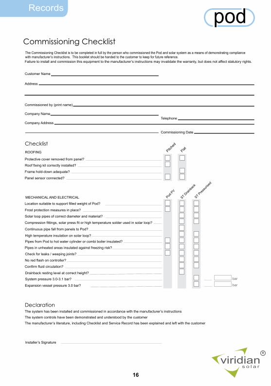
podCommissioning Checklist
The Commissioning Checklist is to be completed in full by the person who commissioned the Pod and solar system as a means of demonstrating compliance with manufacturer’s instructions. This booklet should be handed to the customer to keep for future reference.Failure to install and commission this equipment to the manufacturer’s instructions may invalidate the warranty, but does not affect statutory rights.
Customer Name
Address
Commissioned by (print name)
Company Name
Company AddressTelephone
Commissioning Date
Checklist
Protective cover removed from panel?
Roof fixing kit correctly installed?
Frame hold-down adequate?
bar
Panel sensor connected?
Solar loop pipes of correct diameter and material?
Compression fittings, solar press fit or high temperature solder used in solar loop?
Continuous pipe fall from panels to Pod?
High temperature insulation on solar loop?
Pipes from Pod to hot water cylinder or combi boiler insulated?
Check for leaks / weeping joints?
No red flash on controller?
Confirm fluid circulation?
Drainback resting level at correct height?
System pressure 3.0-3.1 bar?
Expansion vessel pressure 3.0 bar?
The system has been installed and commissioned in accordance with the manufacturer’s instructions
The system controls have been demonstrated and understood by the customer
The manufacturer’s literature, including Checklist and Service Record has been explained and left with the customer
Installer’s Signature
Declaration
ROOFING
MECHANICAL AND ELECTRICAL
bar
ST Drai
nbac
k
ST Pres
suris
ed
Pitche
d
Flat
Pipes in unheated areas insulated against freezing risk?
Pod P
V
Frost protection measures in place?
Location suitable to support filled weight of Pod?
Records
17
viridians o l a r
R
podService Record
1A Technician
Date
Company
Telephone
Notes
Signature
Technician
Date
Company
Telephone
Notes
Signature
3A Technician
Date
Company
Telephone
Notes
Signature
4A Technician
Date
Company
Telephone
Notes
Signature
5B Technician
Date
Company
Telephone
Notes
Signature
6A Technician
Date
Company
Telephone
Notes
Signature
7A Technician
Date
Company
Telephone
Notes
Signature
8A Technician
Date
Company
Telephone
Notes
Signature
9A Technician
Date
Company
Telephone
Notes
Signature
10B Technician
Date
Company
Telephone
Notes
Signature
2A
Records
18
viridians o l a r
R
podService Record
10A Technician
Date
Company
Telephone
Notes
Signature
Technician
Date
Company
Telephone
Notes
Signature
13A Technician
Date
Company
Telephone
Notes
Signature
14A Technician
Date
Company
Telephone
Notes
Signature
15B Technician
Date
Company
Telephone
Notes
Signature
16A Technician
Date
Company
Telephone
Notes
Signature
17A Technician
Date
Company
Telephone
Notes
Signature
18A Technician
Date
Company
Telephone
Notes
Signature
19A Technician
Date
Company
Telephone
Notes
Signature
20B Technician
Date
Company
Telephone
Notes
Signature
12A
viridians o l a r
R
Viridian SolarAtlas Building, 68 Stirling Way
Papworth, Cambridge. CB23 3GY
T 01480 831 501 F 01480 831 831
www.viridiansolar.co.uk
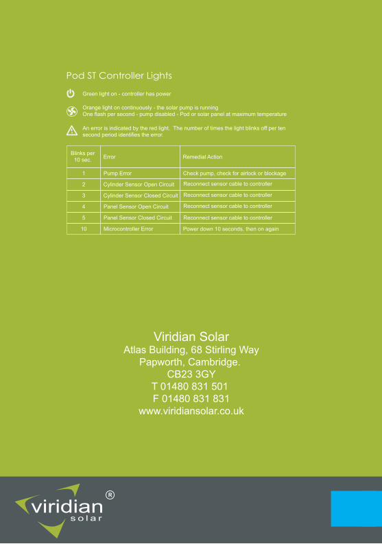
Blinks per 10 sec.
1
2
3
4
5
10
Pod ST Controller Lights
Error
Pump Error
Cylinder Sensor Open Circuit
Cylinder Sensor Closed Circuit
Panel Sensor Open Circuit
Panel Sensor Closed Circuit
Microcontroller Error
Remedial Action
Check pump, check for airlock or blockage
Reconnect sensor cable to controller
Power down 10 seconds, then on again
Reconnect sensor cable to controller
Reconnect sensor cable to controller
Reconnect sensor cable to controller
An error is indicated by the red light. The number of times the light blinks off per ten second period identifies the error.
Orange light on continuously - the solar pump is runningOne flash per second - pump disabled - Pod or solar panel at maximum temperature
Green light on - controller has power