installation operation maintenance manual - euraqua · 9000/9100/9500 duplex series 9xdxiomm\page 1...
TRANSCRIPT

9000/9100/9500 Duplex Series
9xDXIOMM\page 1
InstallationOperationMaintenanceManual
Duplex SoftenerWith 9000/9100/9500 Series
Downflow Brining Valve20-350 litres Resin
Inc. Measuring Tank Option
Models:
Mechanical Meter/Timer
SXT Electronic Meter/Timer

9000/9100/9500 Duplex WatersoftenerInstallation Operation Maintenance Manual
9xDXIOMM\page 2
CONTENTS
NOS. PAGE
1.0 GENERAL NOTES 5
2.0 THE SOFTENING PROCESS 6
2.1 In Service 62.2 Regeneration 62.3 The Regeneration Process 72.4 Meter Control of Regeneration Initiation 72.5 Duplex Operation 8
3.0 UNPACKING AND PARTS IDENTIFICATION 9
3.1 Basic Packages 93.2 Unpacking Notes 93.3 Missing or Damaged Goods 9
4.0 TEMPORARY STORAGE 9
5.0 DESCRIPTION OF PLANT COMPONENTS 10
5.1 Softener Vessel and Internals 105.2 Control Valve 105.3 Regeneration Controller and Transformer 105.4 Brine System 11
6.0 PRE-INSTALLATION CHECKS 12
6.1 Mechanical 12
6.1.1 Foundations/Drainage 126.1.2 Operating Space 126.1.3 Incoming Water 126.1.4 Pipework 136.1.5 Water Supply Company Requirements 13
6.2 Electrical 13

9000/9100/9500 Duplex WatersoftenerInstallation Operation Maintenance Manual
9xDXIOMM\page 3
NOS. PAGE
7.0 ASSEMBLY/INSTALLATION 14
7.1 Mechanical 14
7.1.1 Assembling Vessel, Riser Tube and Internals 147.1.2 Charging the Resin 147.1.4 Assembling the Control Valve 157.1.5 Attatching the Control Valve and Slave Adapter 157.1.6 Brine System 157.1.7 Pipework 157.1.8 Storage tank ball valve 167.1.9 Drains and Overflow Connections 16
7.2 Electrical 17
7.2.1 Mains Supply 177.2.2 Transformer 17
8.0 COMMISSIONING 18
8.1 Introduction 18
8.2 Controller Setting 18
8.2.1 Setting the Time of Day 188.2.2 Site Program – Setting the Capacity 18
8.3 Brine System 19
8.3.1 Brine Tank Filling 19
8.4 Pre Service Flush and Regeneration (MI) 20
8.5 Pre Service Flush and Regeneration (SXT) 22
9000/9100/9500 Duplex WatersoftenerInstallation Operation Maintenance Manual
9xDXIOMM\page 4
NOS. PAGE
9.0 OPERATION 23
9.1 Normal Operation 239.2 Refilling with Salt 239.3 Manual Regeneration 239.4 By-passing the Softener 239.5 Temporary Shut-down 249.6 Changes in Incoming Water 249.7 Routine Monitoring 25
10.0 FAULT FINDING AND RECTIFICATION 26
10.1 No Flow to Service 2610.2 Poor Treated Water Quality 2610.3 No Regeneration 2710.4 Unsatisfactory Capacity between Regeneration’s 27
11.0 WARRANTY AND SERVICE 28
11.1 After Sale Warranty 28
12.0 TECHNICAL DATA 29
12.1 Process and Operating 2912.2 Engineering Data 34
13.0 FACTORY PROGRAMMING
13.1 Regeneration Settings 3913.2 Softener Outputs 4013.3 Master Programming Setup Summary 9000/9100 4113.3 Master Programming Setup Summary 9500 43
14.0 DRAWINGS
14.1 Dimensions 4514.2 General Installation 46
15.0 CE CERTIFICATE 48
APPENDIX IResin MSDS
APPENDIX IIValve manufacturer's manual including parts lists and exploded diagrams

9000/9100/9500 Duplex WatersoftenerInstallation Operation Maintenance Manual
9xDXIOMM\page 5
1.0 GENERAL NOTES
These instructions cover the 9000/9100/9500 Range of Duplex WaterSofteners, which includes models ranging in size from 20-120 litres resinvolume fitter with ¾” – 1.1/2” Mechanical Meter/Timer or SXT ElectronicMeter/Timer.
It is recommended that these instructions are read throughout beforecommencing any work on the unit, particularly if you have no previousexperience of installing and using a water softener.
The installation of a softener is very straightforwards, and the onlyadjustments to be made to the controller program are setting the waterhardness as detailed in Section 8. However we have tried to make theseinstructions as comprehensive as possible to answer any queries you mayhave about the functioning of your softener.
This softener will require salt for regeneration. We recommend the used ofproprietary 'pellet' or 'tablet' salt.
Drinking softened water has not been shown to be harmful to normal healthychildren and adults, but softened water contains a higher level of Sodiumthan a hard town mains supply. This is of concern to individuals on lowSodium diets or for babies fed with powder formula milk that already containsSodium. It is therefore recommended that a separate un-softened drinkingwater supply is left in place or installed on a drinking water faucet. If acartridge type water filter is installed on the drinking water line, this must befed with un-softened water.
We have also supplied with the system the original valve manufacturer'shandbook. This is written principally for American customers and has anumber of small differences in the setting up instructions from those used inEurope. In the event of confusion, refer to the data in this manual ratherthan in the valve manufacturer's handbook!

9000/9100/9500 Duplex WatersoftenerInstallation Operation Maintenance Manual
9xDXIOMM\page 6
2.0 THE SOFTENING PROCESS
Hardness in water is caused by the presence of dissolved salts of Calciumand Magnesium. In order to overcome the problems associated with the useof hard water, these salts must be removed. This process is called'Softening'. One means of removing the salts is to exchange them forsoluble Sodium salts. This technique is known as 'Ion Exchange Softening'.
2.1 IN SERVICE
In order to soften the water, it is passed through a bed of Ion Exchange resinbeads which are contained inside a vertical cylindrical vessel. these beadsare made of a synthetic material, and are usually amber or dark brown incolour and between 0.5 and 1.0 mm in diameter.
As the water flows down through the resin, the Calcium and Magnesium inthe hard water are progressively exchanged for Sodium, with the result thatthe water which flows out of the unit contains only Sodium salts, which arenot scale-forming. The Calcium and Magnesium remain, attached to theresin.
The Ion Exchange resin does not have an unlimited capacity for exchangingCalcium and Magnesium, so to keep the exit water soft it is necessary toperiodically 'Regenerate' the resin to restore its capacity to soften the water.
2.2 REGENERATION
The softening process can be reversed if a strong solution of SodiumChloride (i.e. Common salt dissolved in water -'brine') is passed through theresin.
The high concentration of Sodium allows it to exchange for the Calcium andMagnesium held on the resin, and these are then carried away to drain. Theresin is left full of Sodium to enable it to soften water again.

9000/9100/9500 Duplex WatersoftenerInstallation Operation Maintenance Manual
9xDXIOMM\page 7
2.3 THE REGENERATION PROCESS
The regeneration process consists of four stages:-
Backwash - Water flows upwards through the resin bed, and out to a drain.As it does so, it loosens the ion exchange beads, removes any resin 'fines'(i.e. small pieces of broken beads etc.) and cleans off any particles of dirt orpipework corrosion products which may have accumulated during the servicecycle.
Brine injection/Displacement Rinse - During the first part of this stage, theconcentrated salt -solution is drawn from the salt storage tank, blended withwater to reduce the concentration to the correct level, and passed downthrough the resin. When the required quantity of brine has been drawn in,the water flows alone to push the remaining brine through the resin at thecorrect rate, and ensure that all the resin sees the right amount ofregenerant.
Fast Rinse - This follows the brine injection and displacement rinse stage,and entails rinsing away the residual brine and Calcium and Magnesium saltsfrom the resin and re-packing the resin bed down. This is done down withwater flowing through the resin in the direction of service.
Salt Tank Refill - Following the fast rinse, a quantity of water sufficient todissolve the correct amount of salt for the next regeneration is returned to thesalt tank. When this has finished, the unit automatically returns to service.
2.4 METER CONTROL OF REGENERATION INITIATION
A water meter is installed in the outlet from the softener, to measure thevolume of water which passes to service. This meter drives a turbine, themovement of which is measured by a magnetic sensor which sends signalsto the regeneration controller. The controller microprocessor uses thisinformation to calculate when the unit should be regenerated.
9000/9100/9500 Duplex WatersoftenerInstallation Operation Maintenance Manual
9xDXIOMM\page 8
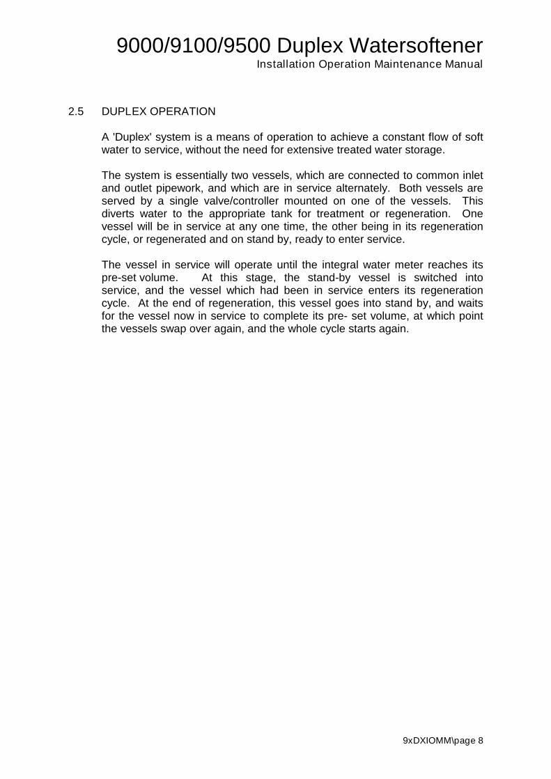
2.5 DUPLEX OPERATION
A 'Duplex' system is a means of operation to achieve a constant flow of softwater to service, without the need for extensive treated water storage.
The system is essentially two vessels, which are connected to common inletand outlet pipework, and which are in service alternately. Both vessels areserved by a single valve/controller mounted on one of the vessels. Thisdiverts water to the appropriate tank for treatment or regeneration. Onevessel will be in service at any one time, the other being in its regenerationcycle, or regenerated and on stand by, ready to enter service.
The vessel in service will operate until the integral water meter reaches itspre-set volume. At this stage, the stand-by vessel is switched intoservice, and the vessel which had been in service enters its regenerationcycle. At the end of regeneration, this vessel goes into stand by, and waitsfor the vessel now in service to complete its pre- set volume, at which pointthe vessels swap over again, and the whole cycle starts again.
9000/9100/9500 Duplex WatersoftenerInstallation Operation Maintenance Manual
9xDXIOMM\page 9
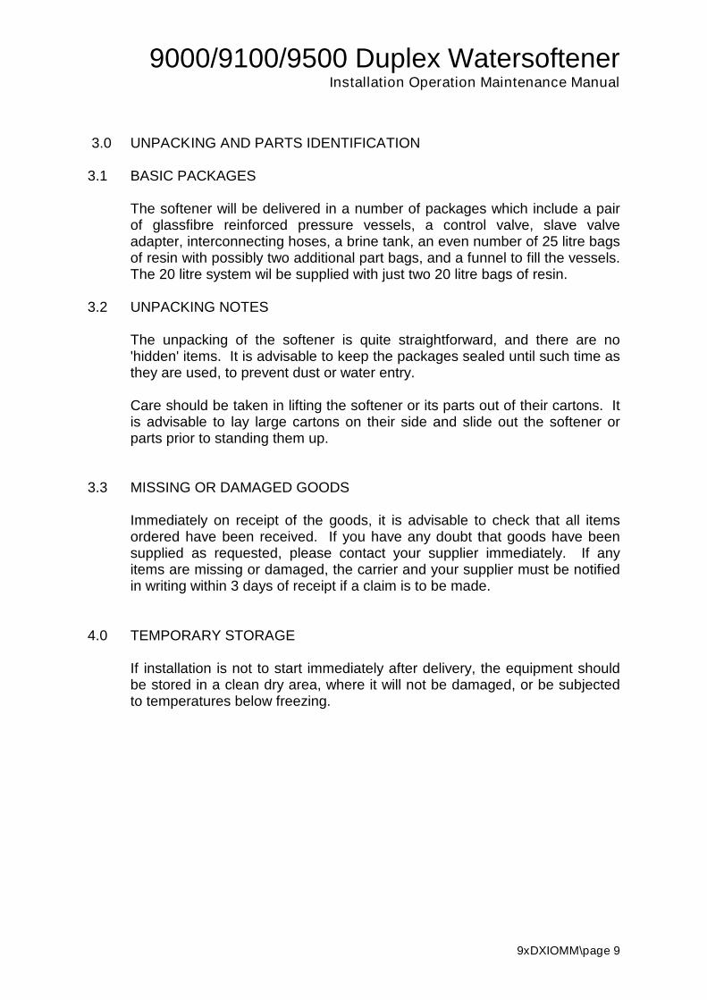
3.0 UNPACKING AND PARTS IDENTIFICATION
3.1 BASIC PACKAGES
The softener will be delivered in a number of packages which include a pairof glassfibre reinforced pressure vessels, a control valve, slave valveadapter, interconnecting hoses, a brine tank, an even number of 25 litre bagsof resin with possibly two additional part bags, and a funnel to fill the vessels.The 20 litre system wil be supplied with just two 20 litre bags of resin.
3.2 UNPACKING NOTES
The unpacking of the softener is quite straightforward, and there are no'hidden' items. It is advisable to keep the packages sealed until such time asthey are used, to prevent dust or water entry.
Care should be taken in lifting the softener or its parts out of their cartons. Itis advisable to lay large cartons on their side and slide out the softener orparts prior to standing them up.
3.3 MISSING OR DAMAGED GOODS
Immediately on receipt of the goods, it is advisable to check that all itemsordered have been received. If you have any doubt that goods have beensupplied as requested, please contact your supplier immediately. If anyitems are missing or damaged, the carrier and your supplier must be notifiedin writing within 3 days of receipt if a claim is to be made.
4.0 TEMPORARY STORAGE
If installation is not to start immediately after delivery, the equipment shouldbe stored in a clean dry area, where it will not be damaged, or be subjectedto temperatures below freezing.

9000/9100/9500 Duplex WatersoftenerInstallation Operation Maintenance Manual
9xDXIOMM\page 10
5.0 DESCRIPTION OF PLANT COMPONENTS
5.1 SOFTENER VESSEL AND INTERNALS
The pressure vessel which contains the ion exchange resin is made from afibreglass/epoxy resin outer layer surrounding an inner, seamless shell made fromPolyethylene, Polypropylene or ABS. Vessels below 80 litre resin capacity have athreaded hole at the top, of 2.5 inch nominal diameter, into which the control valvefits. Vessels for 100 litres of resin or more have larger 4 inch nominal diameterhole and an adapter is supplied to reduce the hole to the 2.5 thread on the valve frouse with 9000 and 9100 valves. The 9500 valve can only be used with 4 inch holevessels.
All vessels are equipped with a distribution system. This is attached to a centralriser tube, which is connected to the control valve, and passes water into and out ofthe resin bed. On smaller systems this will have a single distributor fitted to theriser. On larger and high flow systems there will be multiple distributors built up as a‘hub and laterals’ on the bottom of the riser tube.
5.2 CONTROL VALVE
The control valve is mounted on top of one vessel, and directs the water flow in andout of the resin beds during the service and regeneration cycles. A manifoldassembly or 'slave valve adapter' is mounted on top of vessel No. 2. This is thenconnected to the main control valve via a pair of braided hoses (9000), plasticinterconnect pipes (9100) or copper tubes (9500). The body of the control valve isa brass casting (9000 & 9500) or injection moulded polymer (9100), containingoperating parts made from Teflon and synthetic rubber.
The valve carries out its various functions by moving pistons backwards andforwards in a series of seals and spacers contained within the body casting. Themovement of these pistons is controlled by a rotating cam, which is driven from thecontroller. Further cams in the controller direct the movement of the valvecontrolling the brine system.
5.3 REGENERATION CONTROLLER AND TRANSFORMER
The regeneration controller is attached to the valve, and is contained in a plastichousing.
The controller is powered by 24v AC electricity, and a separate, wall mountedtransformer is connected to the valve to reduce normal mains voltage down from240v so that all the electrical supply in and around the control valve runs at a safe24v.

9000/9100/9500 Duplex WatersoftenerInstallation Operation Maintenance Manual
9xDXIOMM\page 11
5.4 BRINE SYSTEM
The brine system consists of a moulded polyethylene tank into which thebrine well and brine pick up are assembled. The tank forms the salt storagecontainer.
The brine pick-up tube within the brine well is connected to the pipe from thecontrol valve which sucks the brine from the tank. At the bottom of the brinepick-up tube is an air check valve. This serves to prevent air entering thevalve when all the brine has been drawn in. Air in the system could causespurting and 'hammering' at the taps or outlets.
BRINE MEASURING SYSTEM
The Brine Measuring System consists of a measuring tank, brine high levelfloat, brine solenoid and brine pick up. These needs to be fed from a SaltStorage Tank with fully saturated brine solution.
The brine pick-up tube within the brine well is connected to the pipe from thecontrol valve which sucks the brine from the tank. At the bottom of the brinepick-up tube is an air check valve. This serves to prevent air entering thevalve when all the brine has been drawn in. Air in the system could causespurting and 'hammering' at the taps or outlets.

9000/9100/9500 Duplex WatersoftenerInstallation Operation Maintenance Manual
9xDXIOMM\page 12
6.0 PRE-INSTALLATION
6.1 MECHANICAL
6.1.1 Foundation/Drainage
The softener will not require any special foundations, provided that a firm,level area which is capable of supporting the working weight is available.(See Engineering Data, Section 12.2)
Unwanted water from the regeneration process must flow to drain, and so anopen drain or gully, capable of passing the necessary flow is required (seeProcess and Operating Data, 12.1, for relevant flows). The total flow of waterto drain depends on site conditions, but will be approximately 6 times theresin volume. The drain may be at a level no higher than 500mm above thesoftener valve.
A second drain is required for the brine tank overflow. This is a safety drainwhich will only discharge water if there is a malfunction in the control valve.Where possible this should be installed through an outside wall like a cisternoverflow, where it will give a visual indication of any failure.
6.1.2 Operating Space
The space occupied by the softener can be found in the Engineering Data(Section 12.2).,
Access will be required to refill the brine tank, and to carry out adjustments ormaintenance on the equipment. It is therefore recommended that aminimum of 500mm clearance be allowed in front of the unit for this purpose.
6.1.3 Incoming Water
The raw water to be fed to the softener must comply with the following:-
1. Available at all times at a flow equal to the required service flow orgreater, and2. At a pressure between 1.7 and 5.5 bar3. Temperature between 0 and 50oC4. Suspended solids less than 1 ppm5. Iron less than 0.2 ppm, Manganese less than 0.1 ppm, Free Chlorine
less than 1 ppm if temperature is less than 15oC, less than 0.3 ppm iftemperature higher (up to 30oC)

9000/9100/9500 Duplex WatersoftenerInstallation Operation Maintenance Manual
9xDXIOMM\page 13
6.1.4 Pipework
Pipework to be connected to the softener should not have an excessiveamount of hardness scale deposit. Piping that is heavily built up with scale(or Iron deposits) should be replaced.
Make sure that the pipework can be connected to the softener in such a wayas to impose no stresses on the control valve, and that it is properly alignedand supported.
A system for the complete by-passing and isolation of the softener should beinstalled (see Section 7.1.6).
6.1.5 Water Supply Company Requirements
It is essential that if the equipment is to be connected directly to a mainswater supply, the local bylaws must be adhered to. These cover bothplumbing and the prevention of backflow into the mains. If there is anydoubt, the local water inspector should be consulted, but in general, theinstallation of a 'Double check valve assembly' conforming to BS6282 part 2will be required in the feed pipework to the softener.
If the pressure available from the mains is not adequate it will be necessaryto install a booster pump arrangement. Such a system would be covered byadditional bylaws, and the water storage tank needed must comply withthese.
6.2 ELECTRICAL
A continuous supply of 24v, 5 VA is required by the softener. A 240vtransformer with an output of 9.6 VA (70 VA if Brine Measuring System used)is provided, which should be connected to an uninterrupted mains supply,which is separately 1 Amp fused, and does not have any additional switch.
It is recommended that the transformer be attached to a nearby wall, within500 mm of the softener in an area free from water spray or excessive heat orcondensation.
A plug is not provided with this softener since the cable should be connectedto fused spur outlet. However if that is not possible then a plug should befitted to the cable with a 1 amp fuse. The socket used should be un-switchedto prevent the softener from being inadvertently turned off.
9000/9100/9500 Duplex WatersoftenerInstallation Operation Maintenance Manual
9xDXIOMM\page 14
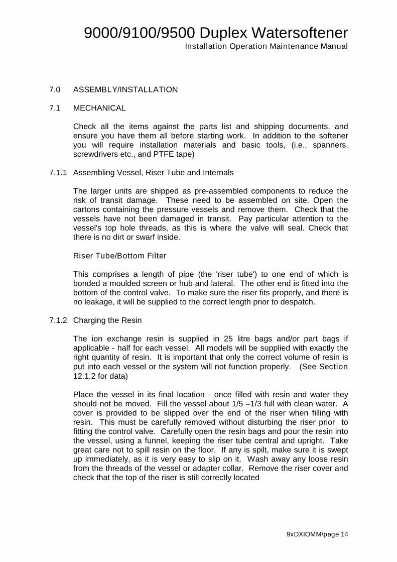
7.0 ASSEMBLY/INSTALLATION
7.1 MECHANICAL
Check all the items against the parts list and shipping documents, andensure you have them all before starting work. In addition to the softeneryou will require installation materials and basic tools, (i.e., spanners,screwdrivers etc., and PTFE tape)
7.1.1 Assembling Vessel, Riser Tube and Internals
The larger units are shipped as pre-assembled components to reduce therisk of transit damage. These need to be assembled on site. Open thecartons containing the pressure vessels and remove them. Check that thevessels have not been damaged in transit. Pay particular attention to thevessel's top hole threads, as this is where the valve will seal. Check thatthere is no dirt or swarf inside.
Riser Tube/Bottom Filter
This comprises a length of pipe (the 'riser tube') to one end of which isbonded a moulded screen or hub and lateral. The other end is fitted into thebottom of the control valve. To make sure the riser fits properly, and there isno leakage, it will be supplied to the correct length prior to despatch.
7.1.2 Charging the Resin
The ion exchange resin is supplied in 25 litre bags and/or part bags ifapplicable - half for each vessel. All models will be supplied with exactly theright quantity of resin. It is important that only the correct volume of resin isput into each vessel or the system will not function properly. (See Section12.1.2 for data)
Place the vessel in its final location - once filled with resin and water theyshould not be moved. Fill the vessel about 1/5 –1/3 full with clean water. Acover is provided to be slipped over the end of the riser when filling withresin. This must be carefully removed without disturbing the riser prior tofitting the control valve. Carefully open the resin bags and pour the resin intothe vessel, using a funnel, keeping the riser tube central and upright. Takegreat care not to spill resin on the floor. If any is spilt, make sure it is sweptup immediately, as it is very easy to slip on it. Wash away any loose resinfrom the threads of the vessel or adapter collar. Remove the riser cover andcheck that the top of the riser is still correctly located

9000/9100/9500 Duplex WatersoftenerInstallation Operation Maintenance Manual
9xDXIOMM\page 15
7.1.4 Assembling the Control Valve
Carefully remove the control valve and the slave tank adapter from theirpacking, and check that all parts are present. On the 9000 and 9100 valves,snap in the bayonet fit distributors to the control valve and slave tankadapter.
7.1.5 Attaching the Control Valve and Slave Adapter
Carefully fit the control valve on to the right hand vessel, taking care toensure that the riser tube locates correctly into the valve base through thetop distributor, and that the threads are not crossed. Also take care to makesure that the 'O' rings are properly seated and not pinched. Repeat theprocess to fit the slave adapter. Connect the two vessels together using thebraided flexible hoses using the swivel coupling end on the slave adapter.The vessel with the slave adapter must be connected to the left hand side ofthe control valve.
Install a suitable service flow controller to the outlet connection of the controlvalve if the treated water is to be supplied in to a storage tank at the samelevel as the system. This will ensure that there is sufficient back pressure forregeneration of the standby vessel.
7.1.6. Brine System
Move brine tank into position and connect the outer port of the bulk headunion to the brine draw connection on the valve using the 3/8" or ½” tubing.Make sure that this connection is also tight to stop air leaking in.
If the brine draw tubing is adjusted for length during installation, ensure thatbrass tubing inserts are refitted into tubing end prior to connecting into brinetank and control valve.
7.1.7 Pipework
Pipework should be assembled incorporating the features shown in theInstallation Diagram, Section 14.1. It is essential that inlet and outlet isolatingvalves and a by-pass valve are provided, and that the water main isprotected by a double check valve where appropriate (see Local Water Bye-laws).
In domestic premises it is recommended that a hard water supply is still usedfor drinking water (see General Notes Section 1.0).
Pipework can be constructed from any normally acceptable material (Copper,Galvanised, Plastic), provided it is properly supported and aligned. Ensurethat the pipe is sufficiently large to accommodate the flow of water required,

9000/9100/9500 Duplex WatersoftenerInstallation Operation Maintenance Manual
9xDXIOMM\page 16
making due allowance for the pressure drop between the softener and thepoint of discharge of soft water.
NOTE: IF BRAZED OR SOLDERED FITTINGS ARE TO BE USED, THEPIPEWORK MUST BE DISCONNECTED FROM THE VALVE DURINGHEATING AND COOLING. EXCESS HEAT CAN CAUSE PERMANENTDAMAGE TO SOME OF THE VALVE COMPONENTS.
The inlet and outlet pipework should be connected to the horizontal, rightfacing connections on the right of the valve manifold (1" BSP Female) (seeFig 1 in Section 14.1).
7.1.8 Storage tank ball valve
Conventional ball float valves pass water at a slow trickle into storage tanksand cisterns when they are shutting off. Trickle flow is not recommended forsatisfactory functioning of a water softener since channelling can occurthrough the resin bed and the meter may not accurately monitor very lowflows. It is therefore recommended that main storage tanks for softenedwater should have the ball valve replaced with a servo type valve such as aTorbeck, Fluidmaster or Aylesbury which permit full flow until they close off.These are inexpensive and are a direct replacement for the more commonbrass ball float valves.
7.1.9 Drains and overflow connections
Connect the overflow fitting on the brine tank to a suitable drain, usingflexible or rigid tubing. Make sure that there is a clear gap of approximately50 mm between the end of the tube and the top of the drain tundish or gullyedge.
The drain connection from the valve is a 1/2" hose spigot (9000 & 9100) or¾” BSPF threaded socket (9500). Flexible tube should be run from thisconnection to a drain capable of taking the maximum flow in regeneration(see Section 12.1), and leaving a similar gap above the drain edge. Thedrain must not be at a higher level than the 500mm above the control valveand preferably should have an air break at the same height as the controlvalve.

9000/9100/9500 Duplex WatersoftenerInstallation Operation Maintenance Manual
9xDXIOMM\page 17
7.2 ELECTRICAL
Electrical installation is very straightforward, but should still be carried out bya competent electrician, and must conform to the appropriate standards ofsafety.
7.2.1 Mains Supply
The mains supply should be through a separate, switched supply, fused andearthed in accordance with Institute of Electrical Engineers Regulations.Current rating should be 1 Amp.
7.2.2 Transformer
A safety transformer is provided to reduce the voltage to 24 Volts to operatethe controls.
This should be attached to a convenient wall, within 500mm of the softener.DO NOT SWITCH ON THE ELECTRICAL SUPPLY AT THIS STAGE
The transformer supply should be connected with the brown cable to the live(fused) terminal in the supply outlet and the blue cable to the neutralterminal. The transformer is double insulated and does not require an earthconnection.

9000/9100/9500 Duplex WatersoftenerInstallation Operation Maintenance Manual
9xDXIOMM\page 18
8.0 COMMISSIONING
8.1 INTRODUCTION
It is recommended that the commissioning of the plant is undertaken by atrained service engineer, who will be able to put the plant into service quickly,and most efficiently. However, if the services of an experienced engineer arenot available, following the steps outlined below will result in the systembeing properly commissioned.
8.2 CONTROLLER SETTING - Site programming mode
All SXT controller settings will require the valve to have a mains supplyswitched on. The valve must not be regenerating when controller settingsare adjusted.
8.2.1 Setting the Time of Day
There is no requirement on the Mechanical Initiation valves to set the time ofday
On SXT timers the display alternates between the time of day, the remainingcalculated capacity in litres before regeneration and the vessel on line (U1 orU2). Wait until the time of day is displayed and the press the up ? and down? arrow keys until the correct time of day is displayed.
8.2.2 Site programming - Setting the capacity and regeneration override.
The softener regeneration cycles have been factory programmed. Thevolume capacity of the resin in litres has also been set up based on a defaulthardness of 21 Degrees Clark (300ppm). This may need to be altered basedon local water hardness (see section 13.2).
There is no regeneration override facility on the Mechanical Initiation valves.
On SXT valves, a regeneration override is used to freshen the resin if aregeneration has not taken place for a number of days.
Press and hold the press the up ? and down ? arrow keys together for 5seconds. The volume capacity of the resin in litres will be displayed. Thiscan be adjusted to suit site conditions by pressing the up and down arrows.

9000/9100/9500 Duplex WatersoftenerInstallation Operation Maintenance Manual
9xDXIOMM\page 19
Press the extra cycle button to set the regeneration override. The default is 3days for duplex softeners. This may be changed to a different interval bypressing the up and down arrows.
Press the extra cycle button to exit the Site Programming mode.
8.3 BRINE SYSTEM
8.3.1 Brine Tank Filling
Place approximately 100 mm depth of water in the bottom of the brine tank.Fill with pellet salt (recommended) until the brine tank it is full or with granularsalt until it is 3/4 full.
Overfilling the brine tank with granular salt can result in an overflow of brine.This cannot happen with pellet salt, which is why it is recommended.
Under no circumstances use cooking salt or Pure Vacuum Dried (PVD) saltto fill the brine tank as either of these will damage the resin and the internalcomponents of the regeneration valve and brine draw system.
8.3.2 Brine Measuring System Filling
Connect the solenoid inlet to the outlet of the Salt saturator (3/4” solventweld) ensure the middle of the two high level floats (mounted side by side) isset at the a height above the brine pick up shut off position corresponding tothe following table.
RESIN QUANTITY(LITRES)
QUANTITY OF BRINE ABOVE PICK UP(LITRES)
20 825 1250 1975 34
100 37120 46150 61190 76200 76250 106300 121350 137

9000/9100/9500 Duplex WatersoftenerInstallation Operation Maintenance Manual
9xDXIOMM\page 20
8.4 PRE-SERVICE FLUSH AND REGENERATION – MECHANICAL TIMERS
Set the manual isolating valves so that water will by-pass the softener. Turnon the main water supply. Open a soft water tap close by and let the waterrun for a few minutes to flush out any debris or foreign matter from thepipework system.
Turn on the power supply to the valve.
Remove the dust cover from the control valve and ensure that the metercable is not plugged into the meter on outlet of the valve. Swing 'open' thetimer assembly on the left of the valve by pulling on its right hand edge. Turnthe manual regeneration knob on the front of the timer clockwise until the firstrow of pins on the program wheel on the back of the timer lifts the outermicroswitch.
Turn on the power supply. The drive motor on the right of the control valvewill run and will start to slowly drive the internal gearing. The bottom shaftwill move first, followed by the top shaft. When both shafts and all the gearshave finished moving the valve is in the backwash position of theregeneration cycle. This will take several minutes. Turn off the powersupply.
Slowly open the water inlet valve. Air will be expelled from the drain line,followed by water once the vessels are filled with water. Open the inlet valvefully to allow water to run to drain for 4-5 minutes.
Turn on the power supply and index the regeneration knob to the 'brine'position - the microswitch is in the first (long) gap in the bank of pins.Water/brine will be drawn in from the brine tank, and water will trickle slowlydown the drain line.
When the gears have stopped moving, index to the rapid rinse section -second bank of pins - and again wait for the gears to stop moving. Water willrun quickly down the drain line.
Index the knob to the brine refill section - second (short) gap in the pins - andwait for the gears to stop moving. Water will be refilled into the brine tank.
Finally, index the knob to the 'home' position past the last pair of pins (innermicroswitch drops into the indent in program wheel) and wait for the gears tostop moving. This has commissioned one vessel.
Leave the power supply on and repeat the sequence in 5) above tocommission the second vessel. However after indexing the knob to the brineposition (iii) leave the timer to drive the program wheel round until the finalpair of pins have lifted the microswitch. This will ensure that the correct
9000/9100/9500 Duplex WatersoftenerInstallation Operation Maintenance Manual
9xDXIOMM\page 21
amount of water has refilled into the brine tank. Finish off by indexing theknob to the home position. This has now commissioned both vessels andthe system is ready for service.
'Close' the timer so that the support leg snaps into the backplate. Adjust thecapacity of the softener if necessary using the reference sheet attached.The units used on the dial are cubic metres (m3). Replace the valve dustcover. Plug the meter cable back into the meter on the outlet of the valve
Open the outlet valve (if fitted) and test the water output from a downstreamtap.
Fill the brine tank with tablet salt to 6" from the top or to 12" from the top ifgranular salt is used (unless Brine Measuring System used).

9000/9100/9500 Duplex WatersoftenerInstallation Operation Maintenance Manual
9xDXIOMM\page 22
8.5 PRE-SERVICE FLUSH AND REGENERATION – SXT TIMERS
Set the manual isolating valves so that water will by-pass the softener. Turnon the main water supply. Open a soft water tap close by and let the waterrun for a few minutes to flush out any debris or foreign matter from thepipework system.
Turn on the power supply to the valve.
Press the extra cycle button for five seconds. The display will then indicate1-----. Wait for the controller to advance the valve until a time in minutesappears on the right of the display.
Slowly open the mains inlet isolating valve until water starts to flow slowlyfrom the drain line. Air will escape initially through the drain line. Whenwater begins to flow steadily, open the valve fully.
Press the 'Extra Cycle' button four times more to return the valve to service.After each press, wait for a time to appear on the right of the display. Therewill be loud 'click' as the brine valve closes while the valve advances fromposition 4 to the home position.
Close the isolating valve and repeat the process to expel air from the secondcolumn.
Finally press the 'Extra Cycle' button to initiate a complete regeneration andrefill the brine tank to the correct level. Do not advance any of the cycles.
9000/9100/9500 Duplex WatersoftenerInstallation Operation Maintenance Manual
9xDXIOMM\page 23
9.0 OPERATION
9.1 NORMAL OPERATION
Operation is completely automatic, with regeneration being initiatedwhenever required by the meter controller.
9.2 REFILLING WITH SALT
Since salt is used in the regeneration process, the level of salt in the brinetank will fall after each regeneration. It should not be allowed to fall below 75mm above the bottom of the cabinet. When the low level is approached (ormore often, as a routine) the cabinet should be refilled to the to top withpellet salt or 3/4 filled with granular salt.
The approximate capacity of the cabinet for salt is shown in Section 12.1.
9.3 MANUAL REGENERATION
There can be occasions during the life of equipment such as softeners whenthe original design basis is not applicable. For example, after a shutdownperiod, the demand for soft water may far exceed the design flow rate for ashort period. Another possibility is that the Water Service Plc finds itnecessary to change to a supply which is much harder than that normallyreceived. It will then be necessary to give the unit an additional regenerationto ensure that soft water continues to be available to service.
This additional regeneration is initiated manually.
Remove the timer cover and index the program wheel knob approximately6mm clockwise until a loud click is heard. Regeneration will proceedautomatically immediately. However due to the slow rotation of the programwheel and piston motors, it will be some minutes until regeneration waterstarts to pass to drain.
9.4 BY-PASSING THE SOFTENER
There may be occasions when it is desirable to by-pass the softener, to allowhard water to go to service, or if the softener is for some reason notperforming properly.
To do this, open the by-pass isolating valve and close the softener outletisolating valve (see Installation Diagram, Fig 3 in Section 14.2). The softenercan still be safely regenerated with the valves in this position. If for anyreason, it is desired to completely isolate the softener, it will be necessary toclose the inlet isolating valve as well.

9000/9100/9500 Duplex WatersoftenerInstallation Operation Maintenance Manual
9xDXIOMM\page 24
9.5 TEMPORARY SHUT-DOWN
If the softener needs to be taken out of service for some time for any otherreason, it is recommended that one or two simple procedures be undertakento ensure the return to operation is as smooth as possible.
1. The unit should be left with both columns fully regeneratedregenerated.
2. The electrical supply should be turned off3. The inlet and outlet manual isolating valves should be closed.4. The valve should be drained of water if there is the possibility of the
system freezing.
On restart, it is recommended that both columns the unit be regeneratedagain before being put into service.
9.6 CHANGES IN INCOMING WATER
There is a much greater tendency these days for the Water supply Plc to usewater from more than one source. It is unlikely that two sources will havesimilar chemical composition, and so when this happens the raw water beingfed to the unit may also change. It is suggested that routine monitoring beundertaken to check whether this is the case (see 9.9). If variation greaterthan 5% is found, it will be necessary to check whether the settings forregeneration need changing. Resetting is the same as setting.
9000/9100/9500 Duplex WatersoftenerInstallation Operation Maintenance Manual
9xDXIOMM\page 25
9.7 ROUTINE MONITORING
The following recommendations are made to help the user of the softenerconfirm that it is performing as required, and to give early warning of possibleproblems. The operation of the softener is completely automatic, and shouldnot require adjustment (except as above).
Weekly
Check the treated water hardness with a hardness test kit.Inspect the level of salt in the salt tank and refill if necessary.
Monthly
Check raw water hardness, and record. Compare with original hardness andadjust volume capacity setting if required (see Section 13.1).
Annually
Inspect and clean/replace as necessary the brine injector, piston and theinternal seals. This should be performed by a competent engineer familiarwith Fleck valves.

9000/9100/9500 Duplex WatersoftenerInstallation Operation Maintenance Manual
9xDXIOMM\page 26
10.0 FAULT FINDING AND RECTIFICATION
Modern water softeners are extremely reliable and unlikely to give anyproblems if they are installed and operated correctly.
10.1 NO FLOW TO SERVICE
Check mains pressure is above 1.7 bar.
Check inlet and outlet isolating valves are open.
Check service outlet valve is open.
Check pressure drop across resin. If excessive, resin may be fouled, orinternals blocked. Initiate a regeneration. If this does not free up the resinthe softener will need to be inspected and serviced by a competent engineer.
10.2 POOR TREATED WATER QUALITY
Check manual by-pass closed.
Check blending valve (if fitted) has not been opened or adjusted.
Check salt level in brine tank. Refill if necessary.
Trickle flow through conventional ball valve in storage tank. Replace withTorbeck, Fluidmaster or Aylesbury servo valve.
Check raw water pressure above minimum. If flow is less than minimum,channelling of water can occur in resin which results in inadequate treatment.
Check injector strainer and injector not blocked (see Appendix for drawings).Clean if necessary.
Check brine pick-up screen not blocked. Clean if necessary.
Check brine line not split. Replace if necessary.
Check raw water hardness, and then check if controller setting is correct forthis hardness (see Section 8)

9000/9100/9500 Duplex WatersoftenerInstallation Operation Maintenance Manual
9xDXIOMM\page 27
10.3 NO REGENERATION
Check electrical supply, fuses etc. satisfactory.
Check control head motor runs, by initiating a manual regeneration.Replace if necessary.
10.4 UNSATISFACTORY CAPACITY BETWEEN REGENERATIONS
See Section 10.2.
Check condition of resin. Resin may have become fouled, inhibiting theregeneration process. If fouled, it should be cleaned or replaced.
Check incoming water for presence of Chlorine. If Chlorine level too high,the resin may have been degraded.
Check raw water pressure. Too high pressure may mean the brine drawstage of regeneration is not effective

9000/9100/9500 Duplex WatersoftenerInstallation Operation Maintenance Manual
9xDXIOMM\page 28
11.0 WARRANTY AND SERVICE
11.1 AFTER SALE WARRANTY
Your softener is covered by a parts warranty for a period of one year frominstallation.
Should you have any problems with your softener or require routine service,please contact your supplier.

9000/9100/9500 Duplex WatersoftenerInstallation Operation Maintenance Manual
9xDXIOMM\page 29
12.1 PROCESS AND OPERATING DATA
12.1.1 9000/9100 Series Water Softeners 20-60 litre
MODEL 20 L 25 L 30 L 40 L 50 L 60L
PARAMETER UNITS
Max. Service M3/hr 0.80 1.00 1.20 1.60 2.00 2.40Flow
Min Service M3/hr 0.10 0.12 0.15 0.20 0.25 0.30Flow
Capacity m3 70 88 105 140 176 210
Volume treatedbetween regens M3 3.3 4.2 5.0 6.7 8.4 10.0(300 ppm CaCO3, 21 Clarke)
Salt used per kg 2.8 3.5 4.2 5.6 7.0 8.4regeneration
Regeneration mins 70 70 70 76 80 80Time
Resin Volume litres 20 25 30 40 50 60
Salt Storage kg 80 120 120 200 200 200Capacity
No of Regens - 28 34 28 35 28 23Salt stored
Maximum Flow Lit/min 5.7 7.5 9.1 9.1 9.1 13.3to drain
IMPORTANT NOTES
Much of the data quoted in the above table is affected by the inlet pressure, and soshould be regarded as nominal only.
Total flow to drain will be similarly affected and is therefore not quoted, but will beabout 6 times the resin volume.

9000/9100/9500 Duplex WatersoftenerInstallation Operation Maintenance Manual
9xDXIOMM\page 30
12.1.2 9000/9100 Series Water Softeners 80-150 litre (9100 80L ¾” only)
MODEL 80 L 100 L 120 L 140L 150L
PARAMETER UNITS MET
Max. Service M3/hr ¾” 3.00 3.00 3.00 3.00 3.00Flow 1” 3.20 4.00 4.00 4.00 4.00
Min Service M3/hr 0.40 0.50 0.60 0.70 0.75Flow
Capacity m3 286 350 420 490 525
Volume treatedbetween regens M3 13.3 16.7 20.0 23.3 25.0(300 ppm CaCO3, 21 Clarke)
Salt used per kg 11.2 14.0 16.8 19.6 21.0regeneration
Regeneration mins 80 82 82 94 96Time
Resin Volume litres 80 100 120 140 150
Salt Storage kg 250 350 500 500 500Capacity
No of Regens - 22 25 29 25 23Salt stored
Maximum Flow Lit/min 15.2 19.2 19.2 26.8 26.8to drain
IMPORTANT NOTES
Much of the data quoted in the above table is affected by the inlet pressure, and soshould be regarded as nominal only.
Total flow to drain will be similarly affected and is therefore not quoted, but will beabout 6 times the resin volume.
9000/9100/9500 Duplex WatersoftenerInstallation Operation Maintenance Manual
9xDXIOMM\page 31
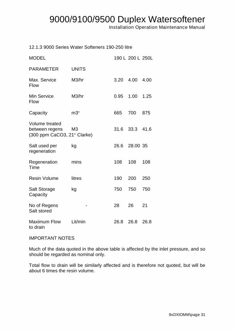
12.1.3 9000 Series Water Softeners 190-250 litre
MODEL 190 L 200 L 250L
PARAMETER UNITS
Max. Service M3/hr 3.20 4.00 4.00Flow
Min Service M3/hr 0.95 1.00 1.25Flow
Capacity m3 665 700 875
Volume treatedbetween regens M3 31.6 33.3 41.6(300 ppm CaCO3, 21 Clarke)
Salt used per kg 26.6 28.00 35regeneration
Regeneration mins 108 108 108Time
Resin Volume litres 190 200 250
Salt Storage kg 750 750 750Capacity
No of Regens - 28 26 21Salt stored
Maximum Flow Lit/min 26.8 26.8 26.8to drain
IMPORTANT NOTES
Much of the data quoted in the above table is affected by the inlet pressure, and soshould be regarded as nominal only.
Total flow to drain will be similarly affected and is therefore not quoted, but will beabout 6 times the resin volume.

9000/9100/9500 Duplex WatersoftenerInstallation Operation Maintenance Manual
9xDXIOMM\page 32
12.1.4 9500 Series Water Softeners 100-150 litre
MODEL 100 L 120 L 140L 150L
PARAMETER UNITS
Max. Service M3/hr 4.00 4.80 5.60 6.00Flow
Min Service M3/hr 0.50 0.60 0.70 0.75Flow
Capacity m3 350 420 490 525
Volume treatedbetween regens M3 16.7 20.0 23.3 25.0(300 ppm CaCO3, 21 Clarke)
Salt used per kg 14.0 16.8 19.6 21.0regeneration
Regeneration mins 82 82 94 96Time
Resin Volume litres 100 120 140 150
Salt Storage kg 350 500 500 500Capacity
No of Regens - 25 29 25 23Salt stored
Maximum Flow Lit/min 19.2 19.2 26.8 26.8to drain
IMPORTANT NOTES
Much of the data quoted in the above table is affected by the inlet pressure, and soshould be regarded as nominal only.
Total flow to drain will be similarly affected and is therefore not quoted, but will beabout 6 times the resin volume.

9000/9100/9500 Duplex WatersoftenerInstallation Operation Maintenance Manual
9xDXIOMM\page 33
12.1.5 9500 Series Water Softeners 190-350 litre
MODEL 190 L 200 L 250L 300 L 350 L
PARAMETER UNITS
Max. Service M3/hr 7.60 8.00 8.40 8.40 8.40Flow
Min Service M3/hr 0.95 1.00 1.25 1.5 1.75Flow
Capacity m3 665 700 875 1050 1225
Volume treatedbetween regens M3 31.6 33.3 41.6 50.00 58.3(300 ppm CaCO3, 21 Clarke)
Salt used per kg 26.6 28.00 35.00 42.00 49.00regeneration
Regeneration mins 96 108 108 108 108Time
Resin Volume litres 190 200 250 300 350
Salt Storage kg 750 750 750 1000 1000Capacity
No of Regens - 28 26 21 23 20Salt stored
Maximum Flow Lit/min 32.2 37.8 37.8 56.8 56.8to drain
IMPORTANT NOTES
Much of the data quoted in the above table is affected by the inlet pressure, and soshould be regarded as nominal only.
Total flow to drain will be similarly affected and is therefore not quoted, but will beabout 6 times the resin volume.

9000/9100/9500 Duplex WatersoftenerInstallation Operation Maintenance Manual
9xDXIOMM\page 34
12.2 ENGINEERING DATA
12.2.1 9000/9100 Series Water Softeners 20-60 lit
MODEL 20 L 25 L 30 L 40 L 50 L 60 L
PARAMETER UNITS
Diameter of vessel/valve mm 170 247 265 265 265 315
Height to top of valve mm 1084 1085 1085 1304 1567 1418
Diameter of brine tank mm 462 462 462 555 555 555
Height of brine tank mm 800 800 800 980 980 980
Inlet Conn. ins BSPF 1.0 1.0 1.0 1.0 1.0 1.0Outlet Conn. ins BSPF 1.0 1.0 1.0 1.0 1.0 1.0
Drain Conn. ins 1/2 1/2 1/2 1/2 1/2 1/2
Brine Tank ins 3/4 3/4 3/4 3/4 3/4 3/4Overflow Conn.
Delivered Wt. Kg. 45 55 75 90 110 150
Working Wt. Kg 150 175 190 350 380 500(approx)Maximum Flow Lit/min 5.7 7.5 9.1 9.1 9.1 13.3to drain
ElectricalPower v 240 240 240 240 240 240
Hz 50 50 50 50 50 50V/A 1.2 1.2 1.2 1.2 1.2 1.2
MAXIMUM OPERATING PRESSURE 5.5 Bar MINIMUM OPERATING PRESSURE1.7 Bar MAXIMUM OPERATING TEMPERATURE 50.0CHEADROOM - Allow 100 mm greater than overall height.
NB Vessels can vary depending on manufacturer used, dimensions aretherefore nominal.

9000/9100/9500 Duplex WatersoftenerInstallation Operation Maintenance Manual
9xDXIOMM\page 35
12.2.2 9000/9100 Series Water Softeners 80-150 lit
MODEL 80 L 100 L 120 L 140 L 150 L
PARAMETER UNITS
Width of vessel/valve mm 334 369 369 406 406
Height to top of valve mm 1561 1850 1850 1850 1850
Diameter of brine tank mm 555 700 830 830 830
Height of brine tank mm 1170 1100 1200 1200 1200
Inlet Conn. ins BSPF 1.0 1.0 1.0 1.0 1.0Outlet Conn. ins BSPF 1.0 1.0 1.0 1.0 1.0
Drain Conn. ins 1/2 1/2 1/2 1/2 1/2
Brine Tank ins 1/2 1/2 1/2 1/2 1/2Overflow Conn.
Delivered Wt. Kg. 190 250 290 350 370
Working Wt. Kg. 550 650 690 870 900(approx)Maximum Flow Lit/min 15.2 19.2 19.2 26.8 26.8to drain
ElectricalPower v 240 240 240 240 240
Hz 50 50 50 50 50V/A 10 10 10 10 10
MAXIMUM OPERATING PRESSURE 5.5 Bar MINIMUM OPERATING PRESSURE1.7 Bar MAXIMUM OPERATING TEMPERATURE 50.0CHEADROOM - Allow 100 mm greater than overall height.
NB Vessels can vary depending on manufacturer used, dimensions aretherefore nominal.
9000/9100/9500 Duplex WatersoftenerInstallation Operation Maintenance Manual
9xDXIOMM\page 36
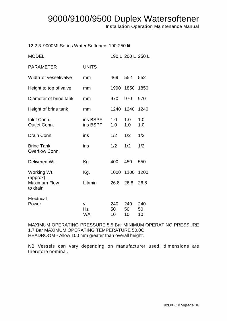
12.2.3 9000MI Series Water Softeners 190-250 lit
MODEL 190 L 200 L 250 L
PARAMETER UNITS
Width of vessel/valve mm 469 552 552
Height to top of valve mm 1990 1850 1850
Diameter of brine tank mm 970 970 970
Height of brine tank mm 1240 1240 1240
Inlet Conn. ins BSPF 1.0 1.0 1.0Outlet Conn. ins BSPF 1.0 1.0 1.0
Drain Conn. ins 1/2 1/2 1/2
Brine Tank ins 1/2 1/2 1/2Overflow Conn.
Delivered Wt. Kg. 400 450 550
Working Wt. Kg. 1000 1100 1200(approx)Maximum Flow Lit/min 26.8 26.8 26.8to drain
ElectricalPower v 240 240 240
Hz 50 50 50V/A 10 10 10
MAXIMUM OPERATING PRESSURE 5.5 Bar MINIMUM OPERATING PRESSURE1.7 Bar MAXIMUM OPERATING TEMPERATURE 50.0CHEADROOM - Allow 100 mm greater than overall height.
NB Vessels can vary depending on manufacturer used, dimensions aretherefore nominal.

9000/9100/9500 Duplex WatersoftenerInstallation Operation Maintenance Manual
9xDXIOMM\page 37
12.2.4 9500 Series Water Softeners 100-150 lit
MODEL 100 L 120 L 140 L 150 L
PARAMETER UNITS
Width of vessel/valve mm 369 369 406 406
Height to top of valve mm 1850 1850 1850 1850
Diameter of brine tank mm 700 830 830 830
Height of brine tank mm 1100 1200 1200 1200
Inlet Conn. ins BSPF 1.5 1.5 1.5 1.5Outlet Conn. ins BSPF 1.5 1.5 1.5 1.5
Drain Conn. ins 3/4 3/4 3/4 3/4
Brine Tank ins 1/2 1/2 1/2 1/2Overflow Conn.
Delivered Wt. Kg. 250 290 350 370
Working Wt. Kg. 650 690 870 900(approx)Maximum Flow Lit/min 19.2 19.2 26.8 26.8to drain
ElectricalPower v 240 240 240 240
Hz 50 50 50 50V/A 10 10 10 10
MAXIMUM OPERATING PRESSURE 5.5 Bar MINIMUM OPERATING PRESSURE1.7 Bar MAXIMUM OPERATING TEMPERATURE 50.0CHEADROOM - Allow 100 mm greater than overall height.
NB Vessels can vary depending on manufacturer used, dimensions aretherefore nominal.

9000/9100/9500 Duplex WatersoftenerInstallation Operation Maintenance Manual
9xDXIOMM\page 38
12.2.5 9500I Series Water Softeners 190-350 lit
MODEL 190 L 200 L 250 L 300 L 350 L
PARAMETER UNITS
Width of vessel/valve mm 469 552 552 610 610
Height to top of valve mm 1990 1850 1850 2000 2000
Diameter of brine tank mm 970 970 970 1050 1050
Height of brine tank mm 1240 1240 1240 1500 1500
Inlet Conn. ins BSPF 1.5 1.5 1.5 1.5 1.5Outlet Conn. ins BSPF 1.5 1.5 1.5 1.5 1.5
Drain Conn. ins 3/4 3/4 3/4 3/4 3/4
Brine Tank ins 1/2 1/2 1/2 1/2 1/2Overflow Conn.
Delivered Wt. Kg. 400 450 550 670 770
Working Wt. Kg. 1000 1100 1200 1900 2000(approx)Maximum Flow Lit/min 32.2 37.8 37.8 56.8 56.8to drain
ElectricalPower v 240 240 240 240 240
Hz 50 50 50 50 50V/A 10 10 10 10 10
MAXIMUM OPERATING PRESSURE 5.5 Bar MINIMUM OPERATING PRESSURE1.7 Bar MAXIMUM OPERATING TEMPERATURE 50.0CHEADROOM - Allow 100 mm greater than overall height.
NB Vessels can vary depending on manufacturer used, dimensions aretherefore nominal.

9000/9100/9500 Duplex Series
9xDXIOMM\page 39
13.0 Factory Programming
13.1 Regeneration Settings9000/9100 valves
Softener Tank B/wash Injector Inj BLFC* Slow Slow B/wash BSR Fast Brine** RegenLit USGPM Std C' rinse rinse time time Rinse refill time time
USGPM lpm time20 835 1.2/1.5 1 0.25 0.40 1.52 6 60 4 8 7025 935 1.5/2.0 1 0.25 0.40 1.52 6 60 4 10 7030 1035 2.4 1 0.25 0.40 1.52 6 60 4 12 7040 1044 2.4 1 0.25 0.40 1.52 6 66 4 16 7650 1054 2.4 1 0.5 0.40 1.52 6 70 4 10 8060 1248 3.5 2 0.5 0.80 3.03 6 70 4 12 8080 1354 4.0 2 0.5 0.80 3.03 6 70 4 16 80
100 1465 5.0 2 1 0.80 3.03 6 70 6 10 82120 1465 5.0 2 1 0.80 3.03 6 70 6 12 82140 1665 7.0 3 1 1.10 4.17 8 80 6 14 94150 1665 7.0 3 1 1.10 4.17 8 80 8 16 96190 1885 7.0 3 1 1.10 4.17 10 90 8 20 108200 2160 7.0 4 1 2.30 8.72 10 90 8 22 108250 2160 7.0 4 1 2.30 8.72 10 90 8 26 108
9500 valvesSoftener Tank B/wash Injector Inj BLFC* Slow Slow B/wash BSR Fast Brine** Regen
Lit USGPM Std C' rinse rinse time Time Rinse refill time timeUSGPM lpm
100 1465 5.0 2 1 0.80 3.03 6 70 6 10 82120 1465 5.0 2 1 0.80 3.03 6 70 6 12 82140 1665 7.0 3 1 1.10 4.17 8 80 6 14 94150 1665 7.0 3 1 1.10 4.17 8 80 8 16 96190 1885 8.5 3 2 1.10 4.17 8 80 8 10 96200 2160 10.0 4 2 2.30 8.72 10 90 10 12 108250 2160 10.0 4 2 2.30 8.72 10 90 10 14 108300 2469 15.0 4 2 2.30 8.72 10 90 10 16 108350 2469 15.0 4 2 2.30 8.72 10 90 10 18 108
* For Brine Measuring System use a 0.25 GPM BLFC for 9000 and 9100 and a 1 GPM BLFC for a 9500 valve** For a Brine Measuring System set to 1 minute
9000/9100/9500 Duplex Series
9xDXIOMM\page 40
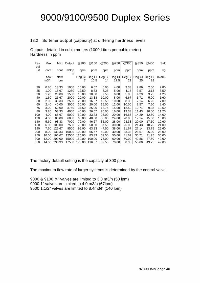
13.2 Softener output (capacity) at differing hardness levels
Outputs detailed in cubic meters (1000 Litres per cubic meter)Hardness in ppm
Resvol
Max Max Output @100 @150 @200 @250 @300 @350 @400 Salt
Lit cont cont m3ppm
ppm ppm ppm ppm ppm ppm ppm kg
flow flow Deg Cl Deg Cl Deg Cl Deg Cl Deg Cl Deg Cl Deg Cl (Nom)m3/h lpm 7 10.5 14 17.5 21 25 28
20 0.80 13.33 1000 10.00 6.67 5.00 4.00 3.33 2.86 2.50 2.8025 1.00 16.67 1250 12.50 8.33 6.25 5.00 4.17 3.57 3.13 3.5030 1.20 20.00 1500 15.00 10.00 7.50 6.00 5.00 4.29 3.75 4.2040 1.60 26.67 2000 20.00 13.33 10.00 8.00 6.67 5.71 5.00 5.6050 2.00 33.33 2500 25.00 16.67 12.50 10.00 8.33 7.14 6.25 7.0060 2.40 40.00 3000 30.00 20.00 15.00 12.00 10.00 8.57 7.50 8.4075 3.00 50.00 3750 37.50 25.00 18.75 15.00 12.50 10.71 9.38 10.5080 3.20 53.33 4000 40.00 26.67 20.00 16.00 13.33 11.43 10.00 11.20
100 4.00 66.67 5000 50.00 33.33 25.00 20.00 16.67 14.29 12.50 14.00120 4.80 80.00 6000 60.00 40.00 30.00 24.00 20.00 17.14 15.00 16.80140 5.60 93.33 7000 70.00 46.67 35.00 28.00 23.33 20.00 17.50 19.60150 6.00 100.00 7500 75.00 50.00 37.50 30.00 25.00 21.43 18.75 21.00190 7.60 126.67 9500 95.00 63.33 47.50 38.00 31.67 27.14 23.75 26.60200 8.00 133.33 10000 100.00 66.67 50.00 40.00 33.33 28.57 25.00 28.00250 10.00 166.67 12500 125.00 83.33 62.50 50.00 41.67 35.71 31.25 35.00300 12.00 200.00 15000 150.00 100.00 75.00 60.00 50.00 42.86 37.50 42.00350 14.00 233.33 17500 175.00 116.67 87.50 70.00 58.33 50.00 43.75 49.00
The factory default setting is the capacity at 300 ppm.
The maximum flow rate of larger systems is determined by the control valve.
9000 & 9100 ¾” valves are limited to 3.0 m3/h (50 lpm)9000 1” valves are limited to 4.0 m3/h (67lpm)9500 1.1/2” valves are limited to 8.4m3/h (140 lpm)
9000/9100/9500 Duplex WatersoftenerInstallation Operation Maintenance Manual
9xDXIOMM\page 41
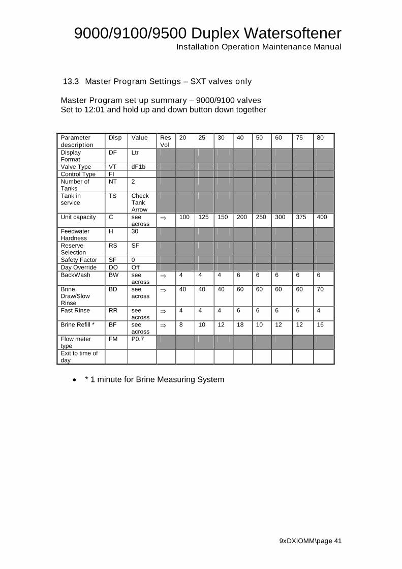
13.3 Master Program Settings – SXT valves only
Master Program set up summary – 9000/9100 valvesSet to 12:01 and hold up and down button down together
Parameterdescription
Disp Value ResVol
20 25 30 40 50 60 75 80
DisplayFormat
DF Ltr
Valve Type VT dF1bControl Type FINumber ofTanks
NT 2
Tank inservice
TS CheckTankArrow
Unit capacity C seeacross
100 125 150 200 250 300 375 400
FeedwaterHardness
H 30
ReserveSelection
RS SF
Safety Factor SF 0Day Override DO OffBackWash BW see
across 4 4 4 6 6 6 6 6
BrineDraw/SlowRinse
BD seeacross
40 40 40 60 60 60 60 70
Fast Rinse RR seeacross
4 4 4 6 6 6 6 4
Brine Refill * BF seeacross
8 10 12 18 10 12 12 16
Flow metertype
FM P0.7
Exit to time ofday
* 1 minute for Brine Measuring System

9000/9100/9500 Duplex WatersoftenerInstallation Operation Maintenance Manual
9xDXIOMM\page 42
Parameterdescription
Disp Value ResVol
100 120 140 150 190 200 250
DisplayFormat
DF Ltr
Valve Type VT dF1bControl Type FINumber ofTanks
NT 2
Tank inservice
TS CheckTankArrow
Unit capacity C seeacross
500 600 700 750 950 1000 1250
FeedwaterHardness
H 30
ReserveSelection
RS SF
Safety Factor SF 0Day Override DO OffBackWash BW see
across 6 6 8 8 10 10 8
BrineDraw/SlowRinse
BD seeacross
70 70 80 80 100 100 120
Fast Rinse RR seeacross
6 6 6 8 8 8 6
Brine Refill * BF seeacross
10 12 14 16 20 20 26
Flow metertype
FM seeacross
P0.7 P1.0 P1.0 P1.0 P1.0 P1.0 P1.0
Exit to time ofday
* 1 minute for Brine Measuring System

9000/9100/9500 Duplex WatersoftenerInstallation Operation Maintenance Manual
9xDXIOMM\page 43
13.4 Master Program Settings – SXT valves only
Master Program set up summary – 9500 valves
Parameterdescription
Disp Value ResVol
100 120 140 150 190 200 250
DisplayFormat
DF seeacross
Ltr Ltr Ltr Ltr Ltr Ltr Ltr
Valve Type VT dF1bControl Type FINumber ofTanks
NT 2
Tank inservice
TS CheckTankArrow
Unit capacity C seeacross
500 600 700 750 950 1000 1300
FeedwaterHardness
H 30
ReserveSelection
RS SF
Safety Factor SF 0Day Override DO OffBackWash BW see
across 6 6 8 8 10 10 8
BrineDraw/SlowRinse
BD seeacross
70 70 80 80 100 100 120
Fast Rinse RR seeacross
6 6 6 8 8 8 6
Brine Refill * BF seeacross
10 12 14 16 20 20 26
Flow metertype
FM P1.5
Exit to time ofday
1 minute for Brine Measuring System

9000/9100/9500 Duplex WatersoftenerInstallation Operation Maintenance Manual
9xDXIOMM\page 44
Parameterdescription
Disp Value ResVol
300 350
DisplayFormat
DF Ltr
Valve Type VT dF1bControl Type FINumber ofTanks
NT 2
Tank inservice
TS CheckTankArrow
Unit capacity C seeacross
1500 1750
FeedwaterHardness
H 30
ReserveSelection
RS SF
Safety Factor SF 0Day Override DO OffBackWash BW see
across 12 10
BrineDraw/SlowRinse
BD seeacross
120 120
Fast Rinse RR seeacross
10 10
Brine Refill * BF seeacross
16 18
Flow metertype
FM P1.5
Exit to time ofday

9000/9100/9500 Duplex WatersoftenerInstallation Operation Maintenance Manual
9xDXIOMM\page 45
14.1 Drawings
MA
XP
RE
SS
UR
E-
8B
AR
MIN
PR
ES
SU
RE
-2
BA
R
BR
INE
LIN
E-3
/8"
DR
AIN
LIN
E-
1/2
"
VA
LV
E-
FL
EC
K9
00
0S
E/1
60
03
/4"
IN/O
UT
CO
NN
EC
TIO
NS
-1
"B
SP
F
CO
NN
EC
TIO
NS
HO
SE
S-
1"
S/S
BR
AID
ED
DR
AW
ING
RE
F:
DU
90
SE
34
/R
A0
20
70
9
CA
PV
ES
SA
BC
DE
FG
HI
J
RE
SIN
RE
F(W
)(H
)
12
.56
35
52
51
08
41
70
33
58
00
46
27
51
95
38
90
4
25
93
56
02
10
85
24
73
35
80
04
62
75
19
53
89
05
30
10
35
62
01
08
52
65
33
58
00
46
27
51
95
38
90
5
40
10
44
62
01
30
42
65
33
59
80
55
57
51
95
38
11
24
50
10
54
62
01
56
72
65
33
59
80
55
57
51
95
38
13
87
60
12
48
67
01
41
83
15
33
59
80
55
57
51
95
38
12
38
75
/80
13
54
84
41
56
13
34
51
01
17
05
55
75
19
53
81
38
1
10
01
46
58
79
18
50
36
95
10
11
00
70
07
51
95
48
16
60
12
01
46
58
79
18
50
36
95
10
90
09
95
75
19
54
81
66
0
DU
PL
EX
W/S
OF
TE
NE
R
MO
DE
L9
00
0S
E
12
.5-1
20
LIT
3/4
"M
ET
ER
E
JB
H
SID
EE
LE
VA
TIO
N
F
I
DR
AIN
INL
ET
/OU
TL
ET
BR
INE
TA
NK
AC
D
TA
NK
1T
AN
K2
G
FR
ON
TE
LE
VA
TIO
N

9000/9100/9500 Duplex WatersoftenerInstallation Operation Maintenance Manual
9xDXIOMM\page 46
MA
XP
RE
SS
UR
E-
8B
AR
MIN
PR
ES
SU
RE
-2
BA
RB
RIN
ELIN
E1600
-3/8
"B
RIN
ELIN
E1700
-1/2
"D
RA
INLIN
E-3
/4"/
1"
VA
LV
E-
FLE
CK
9500/1
600
1.5
"(U
PT
O16")
VA
LV
E-
FLE
CK
9500/1
700
1.5
"(1
8"
UP
WA
RD
S)
IN/O
UT
CO
NN
EC
TIO
NS
-1.5
"B
SP
FC
ON
NE
CT
ION
SH
OS
ES
-1.5
"C
OP
PE
RT
UB
ES
BR
INE
TA
NK
CO
LO
UR
-W
HIT
EO
RB
LU
ED
RA
WIN
GR
EF
:D
U950064
/R
A990623
/0
FR
ON
TE
LE
VA
TIO
NS
IDE
ELE
VA
TIO
N
DU
PLE
XW
/SO
FT
EN
ER
MO
DE
L9500
100-3
50
LIT
1.5
"M
ET
ER
CA
PV
ES
SA
BC
DE
FG
HI
J
RE
SIN
RE
F(W
)(H
)
10
01
46
58
69
18
60
36
95
00
11
00
70
03
55
22
06
51
66
0
12
01
46
58
69
18
60
36
95
00
90
09
95
35
52
20
65
16
60
14
0/1
50
16
65
90
61
86
54
06
50
09
00
99
53
55
22
06
51
66
5
19
01
86
51
17
01
98
74
70
70
01
31
09
95
35
52
20
65
17
87
20
0/2
50
21
60
12
52
18
30
55
27
00
13
10
99
53
55
22
06
51
63
0
30
0/3
50
24
69
13
10
20
80
61
07
00
13
50
10
92
35
52
20
65
18
80
F
E
J
I
H
B
G
INLE
T/O
UT
LE
T
DR
AIN
TA
NK
1T
AN
K2
BR
INE
TA
NK
D
AC

9000/9100/9500 Duplex WatersoftenerInstallation Operation Maintenance Manual
9xDXIOMM\page 47
14.2 Installation Layout
Fig 1 General Installation Layout 9000 Duplex Softeners
Soft Water Outlet
Hard WaterInlet
Mains IsolatingValve
DoubleCheck Valve
BypassValve
OutletIsolatingValve
InletIsolatingValve
PressurisedRegeneration Drain12mm (1/2")
GravityOverflowDrain1/2"
240v 50Hz1 ampContinuousPowerSupply
240-12vTransformer
9000 DuplexSoftener
GeneralInstallationLayout
Drawing GENIN90/RA 020710
Hard DrinkingWater supply
BrineTank
14.2 Measuring system Wiring
9000/9100/9500 Duplex Series
9xDXIOMM\page 48
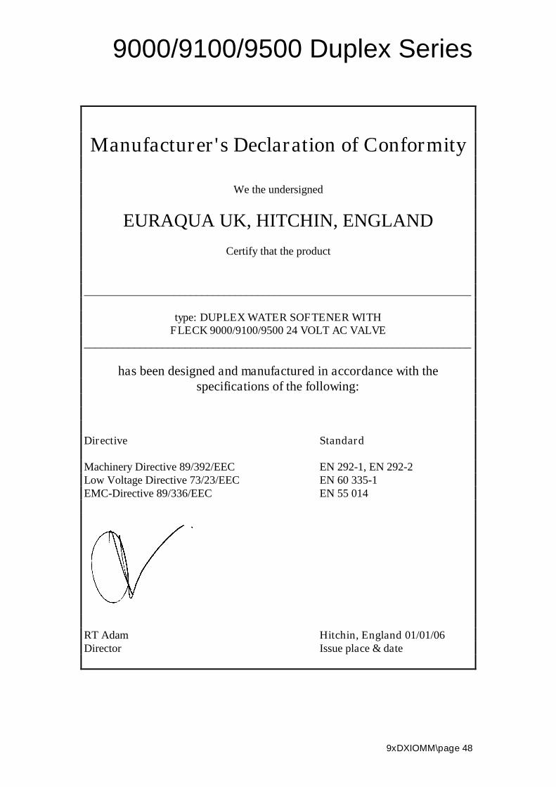
Manufacturer's Declaration of Conformity
We the undersigned
EURAQUA UK, HITCHIN, ENGLAND
Certify that the product
_____________________________________________________________________
type: DUPLEX WATER SOFTENER WITHFLECK 9000/9100/9500 24 VOLT AC VALVE
_____________________________________________________________________
has been designed and manufactured in accordance with thespecifications of the following:
Directive Standard
Machinery Directive 89/392/EEC EN 292-1, EN 292-2Low Voltage Directive 73/23/EEC EN 60 335-1EMC-Directive 89/336/EEC EN 55 014
RT Adam Hitchin, England 01/01/06Director Issue place & date