installation, operation & maintenance manual · 2019-10-22 · installation, operation &...
TRANSCRIPT

INSTALLATION, OPERATION &MAINTENANCE MANUALFor K-Electric Cassette Type Panels: Type-1 & Type-2
As per KE Specification: KDTP-S185-19-01-11kV VCB Cassette Type
PAK ELEKTRON LMITED

PAK ELEKTRON LMITED
INSTALLATION, OPERATION & MAINTENANCE MANUALFor K-Electric Cassette Type Panels: Type-1 & Type-2 as per KE Specification: K-TPRE-VCB-183 (B)
GENERAL
Working on switchgear installation is always a safety risk, both to the personnel and to theequipment.
During assembly & installation in absence of high voltage, risks are usually during liftingor due to pinch injuries, nevertheless electrical safety must be observed as power tools,among others, are used during installation work. However, the greatest risk is whenwork is carried out in a switchgear room where there may be commissioned equipmentin operation.
When commissioning, the risks (both to the personnel and to equipment) must beunderstood as equipment is energized for the first time.
During operations and maintenance, aside from the risks mentioned above, there isalso a risk of damaging the switchgear by some process equipment and thus to thepersonnel working on the process.
When recycling or disposing the material in switchgear, the impact on environment canbe harmful if the equipment is not handled in proposed manner.
The most obvious danger when working with MV switchgear is the mortal danger whenworking with an electrical installation if the applicable electrical safety regulations are notfollowed and if the personnel carrying out work lack the requisite training and knowledge ofelectrical installation.
Switchgear and/or switchboards are recommended to be installed in closed roomssuitable for electrical equipment.
Make sure that installation, operation and maintenance are carried out by specialistelectricians only.
Bear in mind that switchgear in the vicinity can be operated by protective or automatedoperation.
All personnel involved in installation, commissioning, operation, maintenance or repairof equipment must strictly observe these operating instructions.

PAK ELEKTRON LMITED
PERSONAL SAFETY
All site personnel must exercise following safety instructions:
Wear electrical & fire protective clothing. All tools and equipment must be well maintained and suitable for application. Use approved lifting equipment. Never exceed operating limits stated in delivery documents. Never alter or modify a unit without first consulting with the manufacturer. Before applying any supply voltage (power, motor, control, auxiliary etc. circuits) check
whether the voltage and output of the supply are in accordance with required values
EQUIPMENT SAFETY
Do not change the protective settings and blockings without being completely aware of theconsequences. A changed protection setting can affect the protection’s selectivity andjeopardize the operation of entire installation.
GENERAL SYSTEM DESCRIPTION
“Switchgear is a combination of one or more switching devices together with associativecontrol, measuring, signaling, protective and regulatory equipment etc., completely assembledunder the responsibility of manufacturer with all the internal electrical and mechanical inter-connections and structural parts.” (IEC 61439-1)
The metal clad switchgear is a group of units characterized by following features:
The main interrupting device is removable and outfitted with a mechanism for moving itmanually between connected and disconnected positions. It is equipped with selfaligning and self-coupling primary & secondary devices.
The interrupting devices, buses, voltage transformers and power transformers arecompletely enclosed by grounded metal barriers which have no intentional openingsbetween compartments.
All live parts are enclosed with grounded metal compartments. Automatic shutters cover primary circuit elements when the removable element is in
the disconnected, test, or removed position. Primary bus conductors and connections are covered throughout with track resistant
insulating material. Mechanical interlocks are provided to maintain a proper and safe operating sequence.

PAK ELEKTRON LMITED
Instruments, meters, relays, secondary control devices and their wiring are isolated,where necessary, by insulated or grounded metal barriers from all primary circuitelements.
MV switchgear being one of the major power products of PEL is produced for indoor & outdoor(when placed in housing) installations complying with latest international standards i.e. IEC, BSSor VDE. PEL’s switchgears are sheet steel fabricated, totally enclosed, floor mounted, vermin &dust proof. These are supplied with factory fitted relevant components and copper bus bars,internal wiring, terminal blocks etc.
PANEL BASIC STRUCTURE
The cubical housing and doors are fabricated from 2~3 mm thick sheet steel, to form a robustand self supporting structure. Painting procedure includes thorough cleaning, pretreatment andfinal finish in standard RAL colors i.e. RAL-7032/7035 or Customer specified.
PEL make MV switchgear is based on four compartments isolated from each other. Thesecompartments are:
1. LV Control Compartment,2. VCB compartment,3. Instrument Transformer/Cable Compartment4. Busbar Compartment.
Apart from above mentioned, there are variations indesign depending upon operational needs & type ofpanel. Control compartment may vary in terms ofmeasuring & protective instruments andconfiguration. It may be a single compartment or mayhave a partitioning within for metering arrangement.A separate door is provided in case of partitioning.
Presence of CTs & PTs can cause change in configuration. However, critical distances of busbars& their clearances remain same in all types of panels as per relevant standard.
In case of instrument transformer compartment, number/type of CTs & PTs varies dependingupon type of panel. Presence of different types & number of CTs & PTs can cause change inconfiguration. However, critical distances of busbars & their clearances remain same in all typesof panels.

PAK ELEKTRON LMITED
The enclosure of panel is of 2.3~2.5 mm thick high quality sheet steel. Aside from mentioned,internal partitions of desired thickness, made of insulated materials like craft paper, fiberglass,are also provided where necessary.
VENTILATION & PRESSURE RELIEF SYSTEM
The high voltage compartments of panel are equipped with top mounted and secured pressurerelief covers. These are open in case of overpressure due to internal arc fault.
These top mounted pressure relief covers are made of sheet steel and secured with steel boltsand coil spring to retain them to their position against the roof of panel. In case of internaloverpressure, these covers blow up and the pressure is released, the spring then retain themagain back to their position.
The necessary safety measures to counteract the effects of an internal arc fault must beensured in relation to ceiling height.
PANEL INTERLOCKING
To prevent hazardous situation and erroneous operation, interlocking system is provided toprotect both personnel and equipment. The following interlocks must be understood and keptin mind before operation:
Vacuum circuit Breaker can only be inserted in Service Position if earthing switch is off.The earthing switch can only be switched on if main breaker is in Test / Draw outPosition. Both are mechanically interlocked.
If the Front Door is opened, the VCB Cassette cannot be moved into Service Position If the Front Door is not closed, The VCB Cassette cannot be Racked In The Door cannot be opened if VCB is in Service Position. The Door can only be opened if VCB Cassette is in disconnected / Test Position. The Breaker cannot be inserted in ‘Charged’ / ‘ON’ position / without Control Plug. Control Plug cannot be removed in Service Position and Between Test / Service
Positions. If the Earth Switch is in ‘ON’ position the VCB cannot be inserted to ‘Service Position’. If VCB is in ‘Services Position’ then Earth Switch cannot be ‘ON’.
Do not alter factory settings of spring & bolt for pressure relief covers

PAK ELEKTRON LMITED
VCB SAFETY, PRECAUTIONS & INSPECTION INSTRUCTIONS
Safety during installation:
Do not work on the breaker unless the primary circuits are disconnected When connecting bus-bars, tighten bolts using standardized procedures
During operation:
Do not touch the main & control circuit while the product is in operation. The hazardousvoltage can cause serious problem.
Don’t let the product stay in the disconnection position with unlock state. When the heavy product falls down, it can get damaged.
During maintenance: Before any maintenance operation, always open the breaker and make sure that control
& main circuits are not charged. Discharge the spring and open the breaker before performing any maintenance
operation, inspection or repair. Charged closing or tripping spring can cause seriousinjury.
Use the standard pressure torque to tighten the bolts. Loosening of the bolts can causefire.
Handling and installing the breaker:
Wipe the connecting surface with a dry cloth to remove dirt and dust before connecting maincircuit bus-bars and earth terminal and be careful not to shack the draw-out unit and breaker.
Inspection before operation:
Check to see if the breaker is installed properly. Operate the breaker a few times manually to ensure that the breaker is closed and
opened smoothly. Then, operate the breaker using motor operating mechanism withthe auxiliary power, check the ON/OFF indicator and charged state of the closing spring.
Check that no tools and material are left near the breaker. Ground all possible parts of circuit breaker.

PAK ELEKTRON LMITED
DRAW IN & OUT OPERATION OF VCB
VCB can be operated in three positions:
Disconnected / Connected position Test / Service position ON / OFF position
The type of VCB cradles used in panels supplied by PEL: H-Type Cradle- Trolley Type.Recommended Draw In / Out Operations for this type of VCB are stated below:
Method of inserting the circuit breaker:
Open Pad lock and lift handle upward, then open the door and bring the circuit breaker in front of panelby placing it on trolley.
To place in Test position:To move the circuit breaker in test position push handle inward then slightly push the breakerforward until the breaker gets locked from both sides. Then take control plug from housing andfix it in socket. Circuit breaker in this position can be charged and can be turn ON and OFF butcannot be inserted to Service Position with ON / In Charge Position.
PAK ELEKTRON LMITED
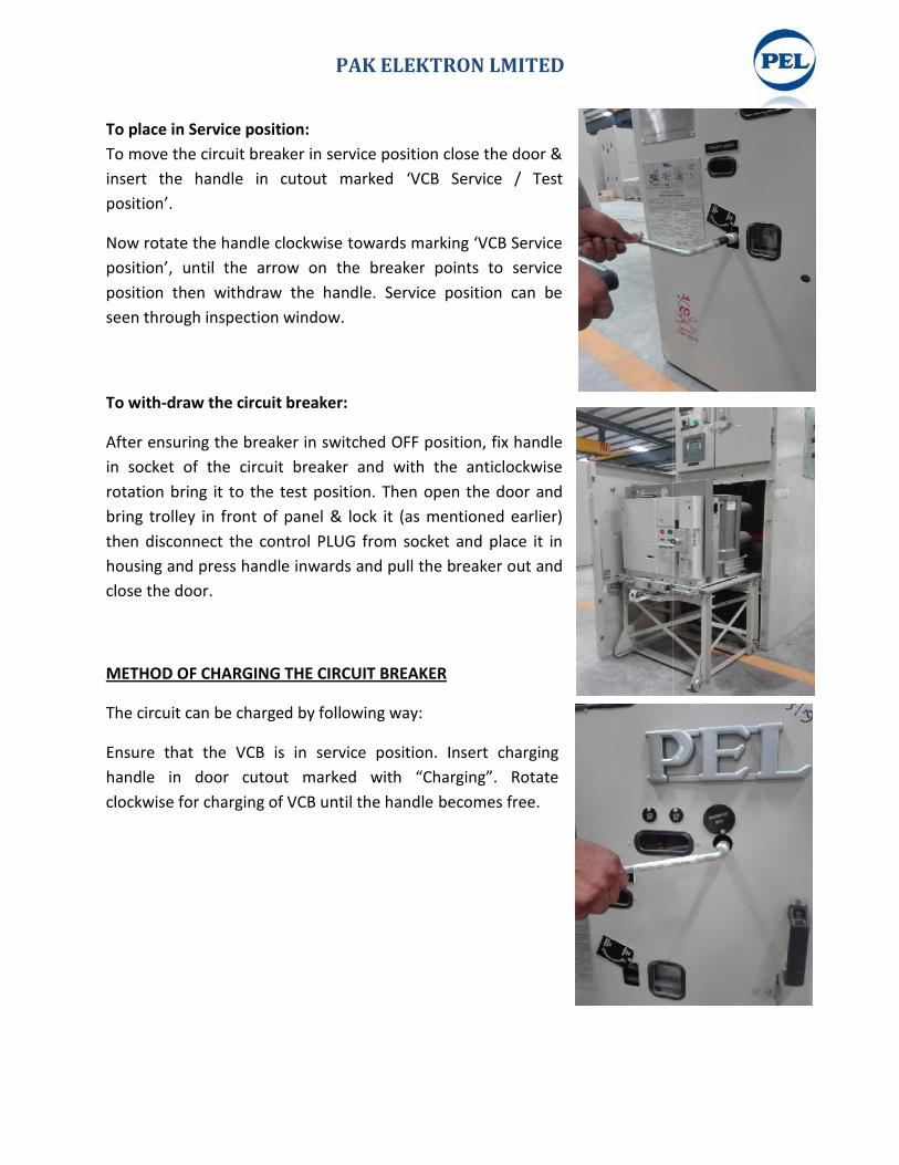
To place in Service position:To move the circuit breaker in service position close the door &insert the handle in cutout marked ‘VCB Service / Testposition’.
Now rotate the handle clockwise towards marking ‘VCB Serviceposition’, until the arrow on the breaker points to serviceposition then withdraw the handle. Service position can beseen through inspection window.
To with-draw the circuit breaker:
After ensuring the breaker in switched OFF position, fix handlein socket of the circuit breaker and with the anticlockwiserotation bring it to the test position. Then open the door andbring trolley in front of panel & lock it (as mentioned earlier)then disconnect the control PLUG from socket and place it inhousing and press handle inwards and pull the breaker out andclose the door.
METHOD OF CHARGING THE CIRCUIT BREAKER
The circuit can be charged by following way:
Ensure that the VCB is in service position. Insert charginghandle in door cutout marked with “Charging”. Rotateclockwise for charging of VCB until the handle becomes free.
PAK ELEKTRON LMITED
To place in Service position:To move the circuit breaker in service position close the door &insert the handle in cutout marked ‘VCB Service / Testposition’.
Now rotate the handle clockwise towards marking ‘VCB Serviceposition’, until the arrow on the breaker points to serviceposition then withdraw the handle. Service position can beseen through inspection window.
To with-draw the circuit breaker:
After ensuring the breaker in switched OFF position, fix handlein socket of the circuit breaker and with the anticlockwiserotation bring it to the test position. Then open the door andbring trolley in front of panel & lock it (as mentioned earlier)then disconnect the control PLUG from socket and place it inhousing and press handle inwards and pull the breaker out andclose the door.
METHOD OF CHARGING THE CIRCUIT BREAKER
The circuit can be charged by following way:
Ensure that the VCB is in service position. Insert charginghandle in door cutout marked with “Charging”. Rotateclockwise for charging of VCB until the handle becomes free.

PAK ELEKTRON LMITED
TO ON / OFF THE CIRCUIT BREAKER
To turn the circuit breaker ON it is mandatory that it should be charged and door should beclosed. To Switch ON the VCB, push the rod after inserting it in the door cutout marked as“ON”. To Switch OFF the VCB, push the rod after inserting it in the door cutout marked as“OFF”.
VCB status can be also seen from window.
MAINTENANCE & INSPECTION
For breaker maintenance & inspection, see breaker catalogue.
OPERATION OF EARTH SWITCH
Prior to operating the Earth Switch, please ensure that the VCBis at TEST / Disconnected / Draw-out position. Mechanicalinterlocking is also provided in panel for safe operation.
To switch ON the Earth Switch, slide the cover upward andinsert the rod inside the hole, then rotate the rod upward asshown.
To switch OFF the Earth Switch, slide the cover upward andinsert the rod inside the hole, then rotate the rod downward asshown.
For corresponding interlocking see details mentioned above in‘Panel Interlocks’ section.

PAK ELEKTRON LMITED
STORAGE & DISPATCH
Packing:
PEL make MV Switchgear cubicles are supplied covered in plastic (Transparent Polyethylenesheet) and strapped vertically to a wooden pallet/crates. The panels are completely factory-assembled, i.e., the withdrawable parts are in the service position and doors are closed andproperly sealed wherever necessary. The switching devices are locked in disconnected positionfor safety reason. Drying agents, usually bags or container of silica gel are provided to protectthem against moisture.
Storage:
Switchgear can be stored at factory premises or at site while considering following:
The switchgear can be stored outdoors under a rain cover/roof withundamaged/unopened packing for maximum of fifteen (15) days.
If storage has to be for more than 15 days, make sure to store in an indoor environmentwith tempered (normal temperature & humidity) conditions. In such cases the storagecan be done for maximum of 12weeks.
If the storage directives are not followed, the equipment can be exposed to corrosionwhich means risk of impaired operation.
LIFTING ARRANGEMENT
MV Metal clad switchgear cubical are provided with lifting lug/lifting eye at the top for liftingpurpose. They can be lifted using fork lift trucks or overhead cranes as shown in figure.
The cable glands will be damaged if the cubical is lifted without wooden pallet with fork lifter.Always prefer lifting through overhead cranes at lifting eye on top.
If, for some reason, the switchgear cubicle cannot be carried vertically, for example, due toconfined doors or elevators, it should be placed on its back.
The warranty undertaking no longer applies with incorrect storage.
Never stay under the lifted switchgear.

PAK ELEKTRON LMITED
TRANSPORTATION & DISPATCHING FOR SITE
The switchgears are designed for road or railway transportation. They aretransported in the form of a completely wrapped unit and can betransported using a trailer of sufficient length and capacity. Make sure tohold the panels with tight ropes after placement on trailer
Keeps an angle of at least 60 degree from the horizontal for the ropesleading to the crane hook. Hang the panel with all four lifting lugs.
.
“Keep Up Right” - “Keep Dry” - “Fragile”
PAK ELEKTRON LMITED
INSTALLATION ON SITE
Unloading & Placement:
The unloading requirements of PEL make switchgear cubicles are same as that of liftingrequirements. Care must be taken to unload the cubicles and carry them to the place ofinstallation. Proper attention should be given to their handling and placement.
From unloading to installation and commissioning, optimum sequence to be ensured byspecially trained & skilled personnel.
Site & Floor Requirement:
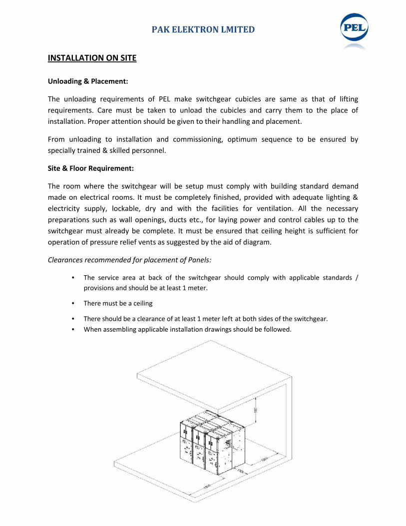
The room where the switchgear will be setup must comply with building standard demandmade on electrical rooms. It must be completely finished, provided with adequate lighting &electricity supply, lockable, dry and with the facilities for ventilation. All the necessarypreparations such as wall openings, ducts etc., for laying power and control cables up to theswitchgear must already be complete. It must be ensured that ceiling height is sufficient foroperation of pressure relief vents as suggested by the aid of diagram.
Clearances recommended for placement of Panels:
The service area at back of the switchgear should comply with applicable standards /provisions and should be at least 1 meter.
There must be a ceiling
There should be a clearance of at least 1 meter left at both sides of the switchgear. When assembling applicable installation drawings should be followed.
PAK ELEKTRON LMITED
INSTALLATION ON SITE
Unloading & Placement:
The unloading requirements of PEL make switchgear cubicles are same as that of liftingrequirements. Care must be taken to unload the cubicles and carry them to the place ofinstallation. Proper attention should be given to their handling and placement.
From unloading to installation and commissioning, optimum sequence to be ensured byspecially trained & skilled personnel.
Site & Floor Requirement:
The room where the switchgear will be setup must comply with building standard demandmade on electrical rooms. It must be completely finished, provided with adequate lighting &electricity supply, lockable, dry and with the facilities for ventilation. All the necessarypreparations such as wall openings, ducts etc., for laying power and control cables up to theswitchgear must already be complete. It must be ensured that ceiling height is sufficient foroperation of pressure relief vents as suggested by the aid of diagram.
Clearances recommended for placement of Panels:
The service area at back of the switchgear should comply with applicable standards /provisions and should be at least 1 meter.
There must be a ceiling
There should be a clearance of at least 1 meter left at both sides of the switchgear. When assembling applicable installation drawings should be followed.

PAK ELEKTRON LMITED
Fixation of panel with foundation:
Foundation plan for all type of MV Panels is shown in figure. Bolts must be grouted to theconcrete foundation according to the dimensions mentioned in diagrams.
Note: ‘ All Dimensions are in mm’
Clean carefully the installation area of switchgear. Remove withdrawable part from the switchgear and store them with a suitable
protection. Carefully place panel on the placement such that bolts pass through the holes of
panel. Carefully inspect level & alignment of the unit. Fix the unit with bolts with special washer and tighten the nuts at rated tightening
torques. Check for final settings, insert withdrawable part again and repeat the sequence for
fixation of other panels (in case of switchboard).
Care must be taken while grouting the bolts into the floor. Boltsshould be straight & not tilted in any direction.
.

PAK ELEKTRON LMITED
COMMISSIONING
Preparatory Work:In preparation for commissioning, the following work must be carried out prior to connectionwith the high voltage power supply:
Check the general condition of switchgear for any damage or defects. Visually inspectthe switching devices, withdrawable parts, isolating contacts, insulating parts,etc.
Check connection of the main earthing bar to the installation earthing conductor(following the appropriate safety regulations).
Check the paintwork for damage and, where necessary. Remove all residues of materials, foreign bodies and tools from the switchgear. Clean the switchgear by rubbing down insulating parts with a soft, dry, clean,
non-fraying cloth. Remove any greasy or sticky dirt. Correctly remount all covers etc. removed during assembly and testing
procedures. Check the VCB contacts Use approx. 5mm screw driver to check the control wiring of whole equipment
tightness. Check the rack in & rack out operation of VCB. Check manual charging operation of VCB
without energizing the system. Perform AC voltage testing of the main circuits where necessary. Pay special
attention to voltage transformers and cables, etc. during this procedure. A testingand earthing module can be used to make the connections
Switch the auxiliary and control voltage on. Carryout testing operations on switching devices manually or by electrical control,
and simultaneously observe the relative position indicators. Check mechanical and electrical interlocks for effectiveness, without using force. Set the protective devices in the switchgear to the required values and check their
function with test equipment.Depending on allocation of responsibilities it may also be necessary to check the followingequipment in areas adjacent to the switchgear:
Power Cables Auxiliary Cables Auxiliary Power Source Remote Control System

PAK ELEKTRON LMITED
Complete Earthing System Switchgear Room Equipment Switchgear Room Conditions
Start-up:
Comply with all relevant safety regulations. Ensure that the circuit-breakers in the system are in the OFF position. Put the VCB on test position Test all the equipment on VCB test position Remove any existing earthing and short circuiting connections in the critical
switching area. Energize the feeder cables. Connect the switchgear step by step, observing the signals and indicators. Check the phase sequence of relative conductors, where necessary, when there
are several incoming feeder cables and switchgear sections. Carry out all measurements and check all functions which depend on high
voltage power supply being connected.
MAINTENANCE & TROUBLESHOOTING
Vacuum Circuit Breakers require little maintenance because of their simplifiedoperating mechanisms and robust construction. In fact, only the parts subject tonormal wear and aging need to be serviced to ensure fully reliable service.
The interval at which these jobs should be carried out and the amount of workinvolved depend upon following factors:
The number of short circuit interruptions The switching frequency The actual service time Environmental conditions
The service intervals indicated below are only approximate and should beadjusted to suit particular operation and above conditions. Under normalcondition the vacuum interrupters need not to be serviced.
Visual Inspection:
The purpose of visual inspection is to check the exterior of the breaker in usualoperation. Once a year, a general visual inspection is should be carried out and the
PAK ELEKTRON LMITED
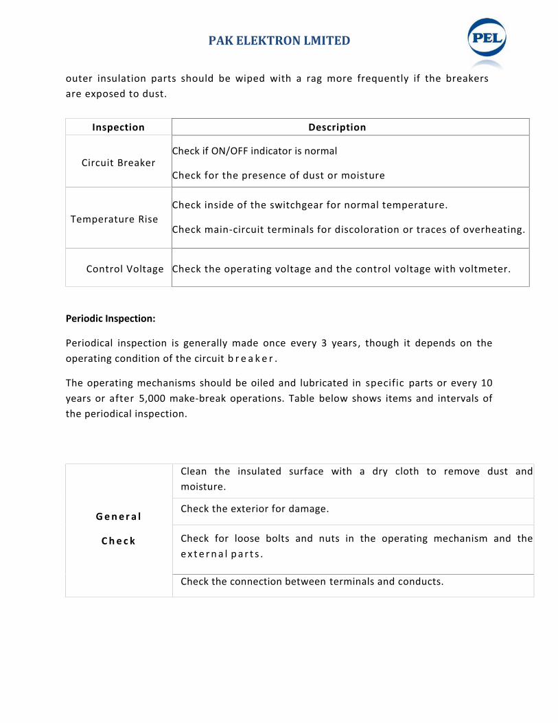
outer insulation parts should be wiped with a rag more frequently if the breakersare exposed to dust.
Periodic Inspection:
Periodical inspection is generally made once every 3 years, though it depends on theoperating condition of the circuit b r e a k e r .
The operating mechanisms should be oiled and lubricated in specific parts or every 10years or after 5,000 make-break operations. Table below shows items and intervals ofthe periodical inspection.
Inspection Description
Circuit BreakerCheck if ON/OFF indicator is normal
Check for the presence of dust or moisture
Check for unusual noise, smell or discoloration
Temperature RiseCheck inside of the switchgear for normal temperature.
Check main-circuit terminals for discoloration or traces of overheating.
Control Voltage Check the operating voltage and the control voltage with voltmeter.
G e n e r a l
C h e c k
Clean the insulated surface with a dry cloth to remove dust andmoisture.
Check the exterior for damage.
Check for loose bolts and nuts in the operating mechanism and thee x t e r n a l p a r t s .
Check the connection between terminals and conducts.
PAK ELEKTRON LMITED
outer insulation parts should be wiped with a rag more frequently if the breakersare exposed to dust.
Periodic Inspection:
Periodical inspection is generally made once every 3 years, though it depends on theoperating condition of the circuit b r e a k e r .
The operating mechanisms should be oiled and lubricated in specific parts or every 10years or after 5,000 make-break operations. Table below shows items and intervals ofthe periodical inspection.
Inspection Description
Circuit BreakerCheck if ON/OFF indicator is normal
Check for the presence of dust or moisture
Check for unusual noise, smell or discoloration
Temperature RiseCheck inside of the switchgear for normal temperature.
Check main-circuit terminals for discoloration or traces of overheating.
Control Voltage Check the operating voltage and the control voltage with voltmeter.
G e n e r a l
C h e c k
Clean the insulated surface with a dry cloth to remove dust andmoisture.
Check the exterior for damage.
Check for loose bolts and nuts in the operating mechanism and thee x t e r n a l p a r t s .
Check the connection between terminals and conducts.

PAK ELEKTRON LMITED
Troubleshooting Guide:
Symptoms Cause Action
Breaker willnot charge
Motor switch off Check the cable of motor line
No control power Check Motor MCB Breakerconnection / position
Motor will not run Replace the motor
Spring charging issue Check the spring charge indicator
O p e r a t i o n T e s t
Operate a few times manually and electrically and check each partfor proper function.
Check ON/OFF indicator and counter for proper function.
Insulation Test onAuxiliary Circuit
Insulation Test can be performed on auxiliary circuit by giving 2kVfor 1 minute.
Check the circuit in case of insulation failure/leakage
Insulation Test onMain Circuit
Power Frequency Test can be performed on main circuit by giving28kV for 1 minute.
Check the circuit in case of insulation failure/leakage
V a c u u mI n t e r r u p t e r
Check the contact erosion. (In closed condition, VI s h ou l d bereplaced if hal f o f th e white mark is visible.)
With the circuit opened, check vacuum degree
PAK ELEKTRON LMITED
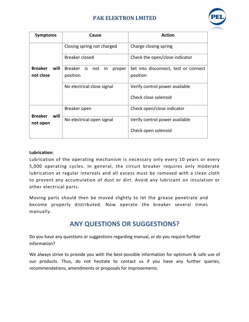
Symptoms Cause Action
Breaker willnot close
Closing spring not charged Charge closing spring
Breaker closed Check the open/close indicator
Breaker is not in properposition
Set into disconnect, test or connectposition
No electrical close signal Verify control power available
Check close solenoid
Breaker willnot open
Breaker open Check open/close indicator
No electrical open signal Verify control power available
Check open solenoid
Lubrication:Lubrication of the operating mechanism is necessary only every 10 years or every5,000 operating cycles. In general, the circuit breaker requires only moderatelubrication at regular intervals and all excess must be removed with a clean clothto prevent any accumulation of dust or dirt. Avoid any lubricant on insulation orother electrical parts.
Moving parts should then be moved slightly to let the grease penetrate andbecome properly distributed. Now operate the breaker several timesmanually.
ANY QUESTIONS OR SUGGESTIONS?
Do you have any questions or suggestions regarding manual, or do you require furtherinformation?
We always strive to provide you with the best-possible information for optimum & safe use ofour products. Thus, do not hesitate to contact us if you have any further queries,recommendations, amendments or proposals for improvements.
PAK ELEKTRON LMITED
Symptoms Cause Action
Breaker willnot close
Closing spring not charged Charge closing spring
Breaker closed Check the open/close indicator
Breaker is not in properposition
Set into disconnect, test or connectposition
No electrical close signal Verify control power available
Check close solenoid
Breaker willnot open
Breaker open Check open/close indicator
No electrical open signal Verify control power available
Check open solenoid
Lubrication:Lubrication of the operating mechanism is necessary only every 10 years or every5,000 operating cycles. In general, the circuit breaker requires only moderatelubrication at regular intervals and all excess must be removed with a clean clothto prevent any accumulation of dust or dirt. Avoid any lubricant on insulation orother electrical parts.
Moving parts should then be moved slightly to let the grease penetrate andbecome properly distributed. Now operate the breaker several timesmanually.
ANY QUESTIONS OR SUGGESTIONS?
Do you have any questions or suggestions regarding manual, or do you require furtherinformation?
We always strive to provide you with the best-possible information for optimum & safe use ofour products. Thus, do not hesitate to contact us if you have any further queries,recommendations, amendments or proposals for improvements.
