installation, operation & maintenance instruction manual · leco nv ir an water tecnoloies...
TRANSCRIPT

DRYING & BLOW-OFF SOLUTIONS
www.almeco.eu
Installation, Operation & Maintenance Instruction Manual
‘EL’ Eye Level DRI-Line Series
2
ALMECO nv Air and water technologiesRoyennestraat 51, B-7700 [email protected] - www.almeco.eu
Table of Contents
INSTALLATION
1. GENERAL INSTRUCTONS
2. GENERAL SAFETY INSTRUCTIONS
3. INSTALLATION
4. TECHNICAL DATA AND EL MATERIALS
OPERATION & MAINTENANCE
5. TIMETABLE FOR KEY MAINTENANCE TASKS
6. GENERAL OPERATIONAL & MAINTENANCE INFORMATION
7. MALFUNCTION-CAUSE-REMEDY
8. CLEANING AND INSPECTION
9. WARRANTY

3
ALMECO nv Air and water technologiesRoyennestraat 51, B-7700 [email protected] - www.almeco.eu
‘EL’ Eye Level Dryer
1. GENERAL INSTRUCTIONS
• Unpack the containers and check off all of the components against the provided delivery notes.• Check for damage on arrival. Please check for any transit damage and report it to Almeco immediately.• Follow installation procedures, outlined in this manual.
Image: Main features of the EL System(Please note - Air knives illustrated)
ACI’s ‘EL’ DRI-Line Series www.bottlecandrying.com
1. GENERAL INSTRUCTIONS Unpack the containers and check off all of the components against the provided delivery notes. Check for damage on arrival. Please check for any transit damage and report it to ACI immediately.
Follow installation procedures, outlined in this manual.
Image: Main features of the EL System (Please note – Air knives illustrated)
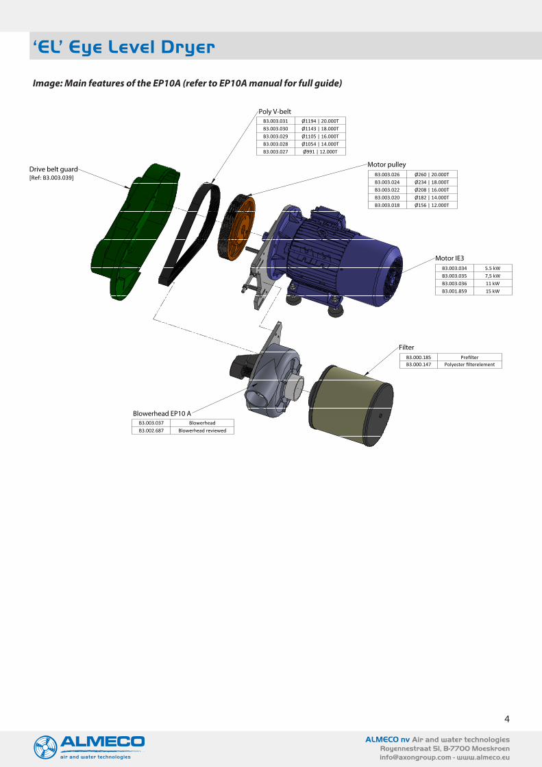
Image: Main features of the EP10A (refer to EP10A manual for full guide)
Acoustic Enclosure (EP10A Compact Blower inside)
EP10A Blower Filter
Air Manifold
Flexible Ducting
Air Delivery Device – Air Knives illustrated
Conveyor (not supplied)
Leg Kit
Filter (part no: KB-234)
Fancase (part no: EP-008)
Spindle Assembly (part no: EP-241)
Drive Belt /Pulley Drive part no: EP-100 Ø1194mm EP-101 Ø1143mm EP-102 Ø1054mm EP-103 Ø991mm EP-104 Ø1105mm
Drive Belt Guard (part no; EP-035/R59)
Motor
4
ALMECO nv Air and water technologiesRoyennestraat 51, B-7700 [email protected] - www.almeco.eu
‘EL’ Eye Level Dryer
Image: Main features of the EP10A (refer to EP10A manual for full guide)
Drive belt guard
Poly V-belt
Motor pulley
Motor IE3
Blowerhead EP10 A
Filter
[Ref: B3.003.039]
B3.000.185 PrefilterB3.000.147 Polyester filterelement
B3.003.031 Ø1194 | 20.000TB3.003.030 Ø1143 | 18.000TB3.003.029 Ø1105 | 16.000TB3.003.028 Ø1054 | 14.000TB3.003.027 Ø991 | 12.000T
B3.003.026 Ø260 | 20.000TB3.003.024 Ø234 | 18.000TB3.003.022 Ø208 | 16.000TB3.003.020 Ø182 | 14.000TB3.003.018 Ø156 | 12.000T
B3.003.034 5.5 kWB3.003.035 7,5 kWB3.003.036 11 kWB3.001.859 15 kW
B3.003.037 BlowerheadB3.002.687 Blowerhead reviewed
5
ALMECO nv Air and water technologiesRoyennestraat 51, B-7700 [email protected] - www.almeco.eu
‘EL’ Eye Level Dryer
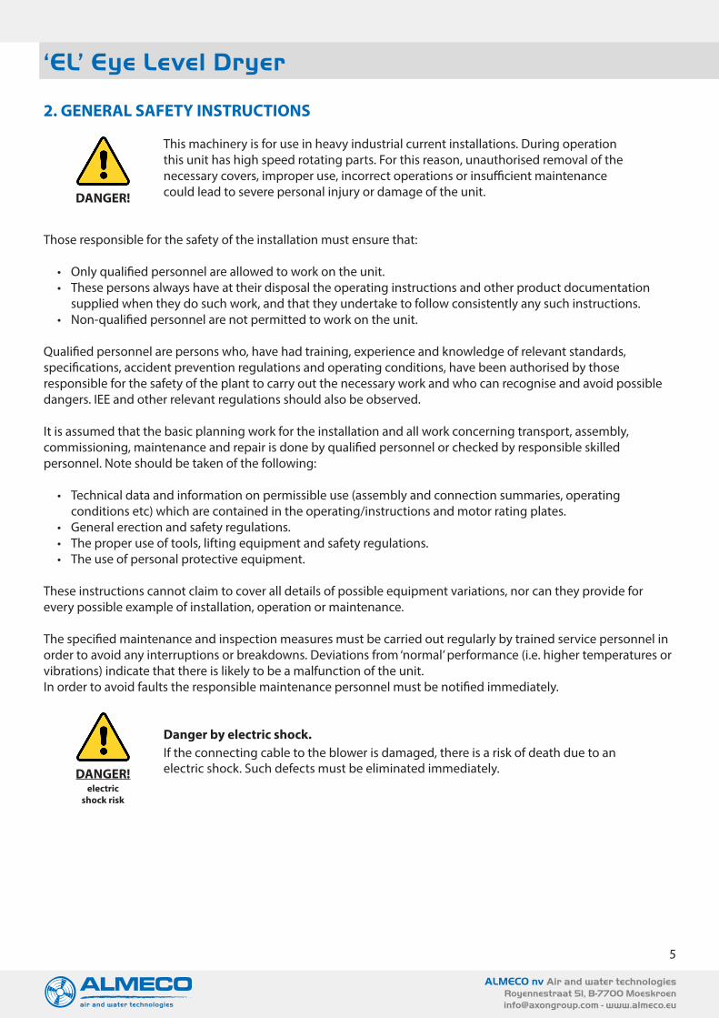
2. GENERAL SAFETY INSTRUCTIONS
This machinery is for use in heavy industrial current installations. During operation this unit has high speed rotating parts. For this reason, unauthorised removal of the necessary covers, improper use, incorrect operations or insufficient maintenance could lead to severe personal injury or damage of the unit.
Those responsible for the safety of the installation must ensure that:
• Only qualified personnel are allowed to work on the unit.• These persons always have at their disposal the operating instructions and other product documentation
supplied when they do such work, and that they undertake to follow consistently any such instructions.• Non-qualified personnel are not permitted to work on the unit.
Qualified personnel are persons who, have had training, experience and knowledge of relevant standards, specifications, accident prevention regulations and operating conditions, have been authorised by those responsible for the safety of the plant to carry out the necessary work and who can recognise and avoid possible dangers. IEE and other relevant regulations should also be observed.
It is assumed that the basic planning work for the installation and all work concerning transport, assembly, commissioning, maintenance and repair is done by qualified personnel or checked by responsible skilled personnel. Note should be taken of the following:
• Technical data and information on permissible use (assembly and connection summaries, operating conditions etc) which are contained in the operating/instructions and motor rating plates.
• General erection and safety regulations.• The proper use of tools, lifting equipment and safety regulations.• The use of personal protective equipment.
These instructions cannot claim to cover all details of possible equipment variations, nor can they provide for every possible example of installation, operation or maintenance.
The specified maintenance and inspection measures must be carried out regularly by trained service personnel in order to avoid any interruptions or breakdowns. Deviations from ‘normal’ performance (i.e. higher temperatures or vibrations) indicate that there is likely to be a malfunction of the unit.In order to avoid faults the responsible maintenance personnel must be notified immediately.
Danger by electric shock.If the connecting cable to the blower is damaged, there is a risk of death due to an electric shock. Such defects must be eliminated immediately.
DANGER!
DANGER! electric
shock risk

6
ALMECO nv Air and water technologiesRoyennestraat 51, B-7700 [email protected] - www.almeco.eu
‘EL’ Eye Level Dryer
3. INSTALLATION
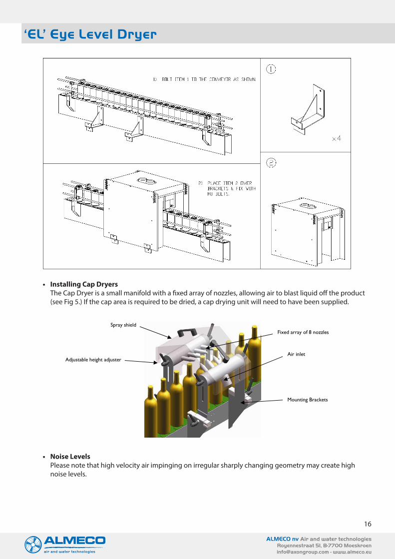
• Installation site demandsUpon delivery of the unit to its place of installation, all safety precautions must be followed. Fork lift trucks, elevators or cranes with enough carrying capacity and stability should be used, and the transport and installation should only be carried out by qualified personnel.Open the crate lid & long side which does not house the leg kit (use a pozi-drive screwdriver). The EL enclosure (shown below) will be on its own internal pallet. Unscrew the EL pallet (from the crate) & remove to a convenient location. Unpack the leg kit & all other items.
ACI’s ‘EL’ DRI-Line Series www.bottlecandrying.com
3. INSTALLATION.
Installation site demands.
Upon delivery of the unit to its place of installation, all safety precautions must be followed. Fork lift trucks, elevators or cranes with enough carrying capacity and stability should be used, and the transport and installation should only be carried out by qualified personnel.
Open the crate lid & long side which does not house the leg kit (use a pozi-drive screwdriver). The EL enclosure (shown below) will be on its own internal pallet. Unscrew the EL pallet (from the crate) & remove to a convenient location. Unpack the leg kit & all other items.
Mounting Erect leg kit into the chosen position under the existing conveyor line. Connect and secure all ducting. Connect Blower. Refer to Electrical Connections overleaf.
Ground Fastenings In order for the system to be securely positioned the leg kit and the top enclosure will need to be attached and secured together.
Erect leg kit into the chosen position under the existing conveyor line.
Position top enclosure onto leg kit. – secure each 4 corner positions by tightening bolt with a 17mm spanner.
Once the leg kit has been secured, the EL Drying unit is completely free standing. However, ACI recommend additional support at the fixing points. Demands of the installation site. If no other special equipment is supplied, the following requirements should apply to the installation site.
The unit is designed for use inside closed production rooms protected against any weather conditions. The unit is not designed for use outside.
Installation requires an industrial type or concrete floor.
Sling in these places to lift enclosure
Feet can be fixed to the floor
Fixing points on all sides to support if required
• Mounting• Erect leg kit into the chosen position under the existing conveyor line.• Connect and secure all ducting.• Connect Blower. Refer to Electrical Connections overleaf.
• Ground FasteningsIn order for the system to be securely positioned the leg kit and the top enclosure will need to be attached and secured together.
• Erect leg kit into the chosen position under the existing conveyor line.
• Position top enclosure onto leg kit. – secure each 4 corner positions by tightening bolt with a 17mm spanner.
Once the leg kit has been secured, the EL Drying unit is completely free standing. However, Almeco recommend additional support at the fixing points.
• Demands of the installation siteIf no other special equipment is supplied, the following requirements should apply to the installation site.
• The unit is designed for use inside closed production rooms protected against any weather conditions. The unit is not designed for use outside.
• Installation requires an industrial type or concrete floor.
ACI’s ‘EL’ DRI-Line Series www.bottlecandrying.com
3. INSTALLATION.
Installation site demands.
Upon delivery of the unit to its place of installation, all safety precautions must be followed. Fork lift trucks, elevators or cranes with enough carrying capacity and stability should be used, and the transport and installation should only be carried out by qualified personnel.
Open the crate lid & long side which does not house the leg kit (use a pozi-drive screwdriver). The EL enclosure (shown below) will be on its own internal pallet. Unscrew the EL pallet (from the crate) & remove to a convenient location. Unpack the leg kit & all other items.
Mounting Erect leg kit into the chosen position under the existing conveyor line. Connect and secure all ducting. Connect Blower. Refer to Electrical Connections overleaf.
Ground Fastenings In order for the system to be securely positioned the leg kit and the top enclosure will need to be attached and secured together.
Erect leg kit into the chosen position under the existing conveyor line.
Position top enclosure onto leg kit. – secure each 4 corner positions by tightening bolt with a 17mm spanner.
Once the leg kit has been secured, the EL Drying unit is completely free standing. However, ACI recommend additional support at the fixing points. Demands of the installation site. If no other special equipment is supplied, the following requirements should apply to the installation site.
The unit is designed for use inside closed production rooms protected against any weather conditions. The unit is not designed for use outside.
Installation requires an industrial type or concrete floor.
Sling in these places to lift enclosure
Feet can be fixed to the floor
Fixing points on all sides to support if required
Fixing points on all sides to support if required
Feet can be fixed to the floor

7
ALMECO nv Air and water technologiesRoyennestraat 51, B-7700 [email protected] - www.almeco.eu
‘EL’ Eye Level Dryer
• Electrical Connections• Almeco recommend that a soft start with integrated thermistor control is used to start the blower.• A second option is an inverter drive can be used with a ramp up of 6 seconds or over. Finally a star/delta
starter can be used, but this is not preferred.• Customers should always check the motor direction of rotation upon installation.• All wiring should be installed to national wiring standards.
• Test Run - Direction of rotation (EP10A blower motor)
Incorrect fan rotation is the most common cause of unit under-performance so great care must be taken here. The direction of the motor cooling fan should be as per the arrow fitted to the motor cowl.
If the motor is running in the incorrect direction, it can be reversed by exchanging two phase leads.
When connecting the blower, ensure that the motor rotates in the correct direction (non drive end / motor cooling fan end). This is the main reason for systems underperforming!!
• Control• The EL units are designed to run continuously. Avoid frequent stop starts – Almeco recommend no more
than 6 (six) start/stop cycles per hour• If the blower control is linked to other equipment then ensure that this does not have frequent switching
on and off, if so then use a timer delay in the control to avoid frequent switching.• The EP10A blower needs to have airflow passing through it to ensure temperatures are not exceeded.
The use of control valves should be limited to ensure that at least 150 CFM passes through the head at all times.
• Avoid using fast acting valves and diverter valves in the ducting. This can cause sudden back pressure changes which may harm the blower.
ACI’s ‘EL’ DRI-Line Series www.bottlecandrying.com
Electrical Connections
ACI recommend that a soft start with integrated thermistor control is used to start the blower.
A second option is an inverter drive can be used with a ramp up of 6 seconds or over. Finally a star/delta starter can be used, but this is not preferred.
Customers should always check the motor direction of rotation upon installation. All wiring should be installed to national wiring standards.
Test Run - Direction of rotation (EP10A blower motor)
EP10A Electric Motor Terminal Box
Incorrect fan rotation is the most common cause of unit under-performance so great care must be taken here. The direction of the motor cooling fan should be as per the arrow fitted to the motor cowl. If the motor is running in the incorrect direction, it can be reversed by exchanging two phase leads.
Control
ACI’s EL units are designed to run continuously. Avoid frequent stop starts – ACI recommend no more than 6 (six) start/stop cycles per hour
If the blower control is linked to other equipment then ensure that this does not have frequent switching on and off, if so then use a timer delay in the control to avoid frequent switching.
The EP10A blower needs to have airflow passing through it to ensure temperatures are not exceeded. The use of control valves should be limited to ensure that at least 150 CFM passes through the head at all times.
Avoid using fast acting valves and diverter valves in the ducting. This can cause sudden back pressure changes which may harm the blower
When connecting the blower, ensure that the motor rotates in the correct direction (non drive end / motor cooling fan end). This is the main reason for systems underperforming!!
EP10A Electric Motor Terminal Box

8
ALMECO nv Air and water technologiesRoyennestraat 51, B-7700 [email protected] - www.almeco.eu
‘EL’ Eye Level Dryer
Wiring diagram: Star / Delta Starter (1 of 4)
ACI’s
‘EL’
DRI
-Lin
e Se
ries
w
ww
.bot
tleca
ndry
ing.
com
Wiri
ng d
iagr
am:
Star
/ De
lta S
tart
er (1
of 4
)
9
ALMECO nv Air and water technologiesRoyennestraat 51, B-7700 [email protected] - www.almeco.eu
‘EL’ Eye Level Dryer
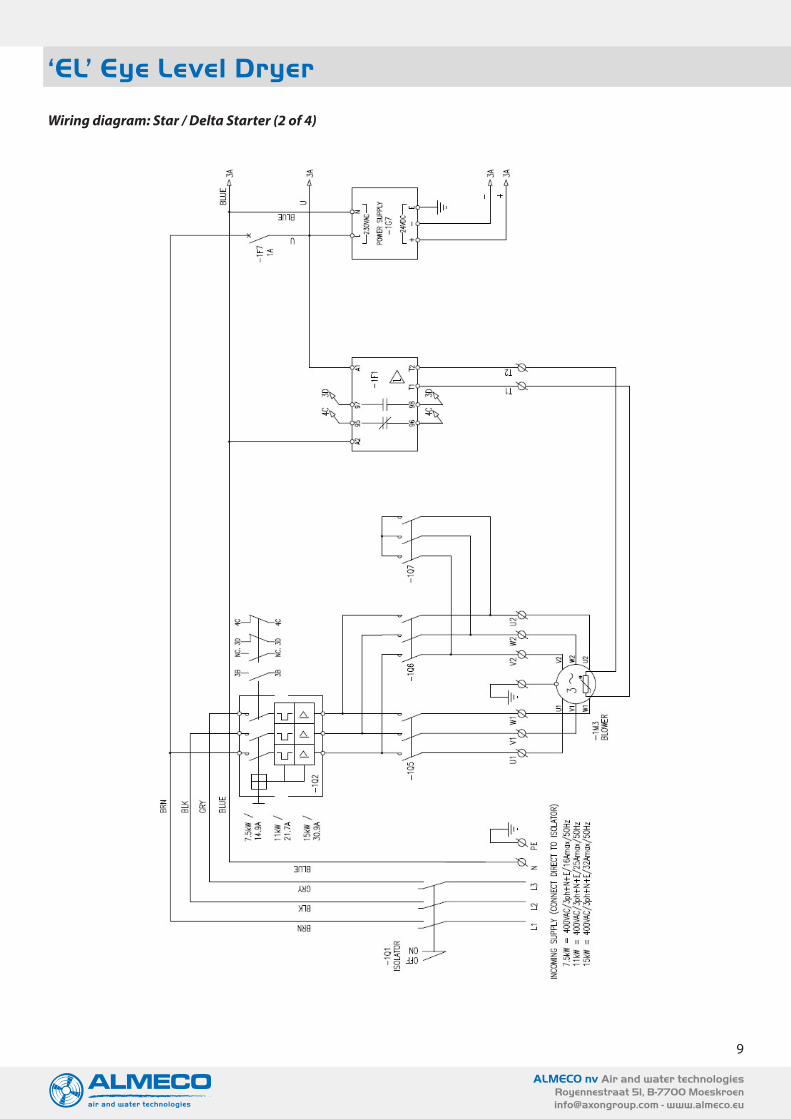
Wiring diagram: Star / Delta Starter (2 of 4)
ACI’s
‘EL’
DRI
-Lin
e Se
ries
w
ww
.bot
tleca
ndry
ing.
com
Wiri
ng d
iagr
am: S
tar /
Del
ta S
tart
er (2
of 4
)

10
ALMECO nv Air and water technologiesRoyennestraat 51, B-7700 [email protected] - www.almeco.eu
‘EL’ Eye Level Dryer
Wiring diagram: Star / Delta Starter (3 of 4)
ACI’s
‘EL’
DRI
-Lin
e Se
ries
w
ww
.bot
tleca
ndry
ing.
com
Wiri
ng d
iagr
am: S
tar /
Del
ta S
tart
er (3
of 4
)
11
ALMECO nv Air and water technologiesRoyennestraat 51, B-7700 [email protected] - www.almeco.eu
‘EL’ Eye Level Dryer
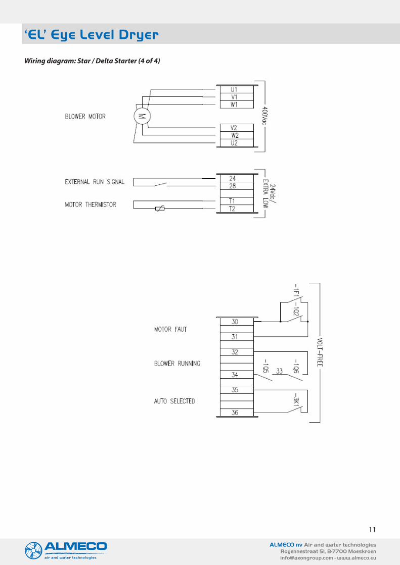
Wiring diagram: Star / Delta Starter (4 of 4)
ACI’s ‘EL’ DRI-Line Series www.bottlecandrying.com
Wiring diagram: Star / Delta Starter (4 of 4)
12
ALMECO nv Air and water technologiesRoyennestraat 51, B-7700 [email protected] - www.almeco.eu
‘EL’ Eye Level Dryer
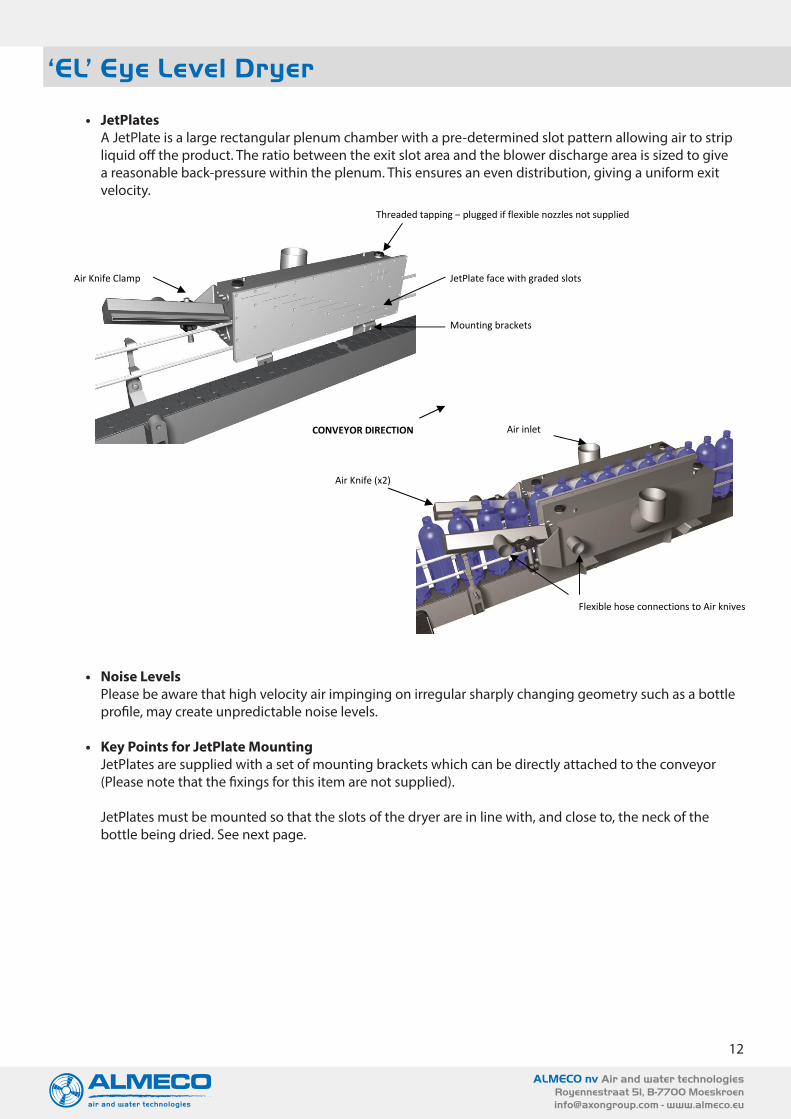
• JetPlatesA JetPlate is a large rectangular plenum chamber with a pre-determined slot pattern allowing air to strip liquid off the product. The ratio between the exit slot area and the blower discharge area is sized to give a reasonable back-pressure within the plenum. This ensures an even distribution, giving a uniform exit velocity.
• Noise LevelsPlease be aware that high velocity air impinging on irregular sharply changing geometry such as a bottle profile, may create unpredictable noise levels.
• Key Points for JetPlate MountingJetPlates are supplied with a set of mounting brackets which can be directly attached to the conveyor (Please note that the fixings for this item are not supplied).
JetPlates must be mounted so that the slots of the dryer are in line with, and close to, the neck of the bottle being dried. See next page.
ACI’s ‘EL’ DRI-Line Series www.bottlecandrying.com
ACI JetPlates
A JetPlate is a large rectangular plenum chamber with a pre-determined slot pattern allowing air to strip liquid off the product. The ratio between the exit slot area and the blower discharge area is sized to give a reasonable back-pressure within the plenum. This ensures an even distribution, giving a uniform exit velocity.
Noise Levels Please be aware that high velocity air impinging on irregular sharply changing geometry such as a bottle profile, may create unpredictable noise levels.
Key Points for JetPlate Mounting JetPlates are supplied with a set of mounting brackets which can be directly attached to the conveyor (Please note that the fixings for this item are not supplied). JetPlates must be mounted so that the slots of the dryer are in line with, and close to, the neck of the bottle being dried. See next page.
Threaded tapping – plugged if flexible nozzles not supplied
JetPlate face with graded slots
Mounting brackets
Air inlet
Air Knife (x2)
Flexible hose connections to Air knives
Air Knife Clamp
CONVEYOR DIRECTION
13
ALMECO nv Air and water technologiesRoyennestraat 51, B-7700 [email protected] - www.almeco.eu
‘EL’ Eye Level Dryer
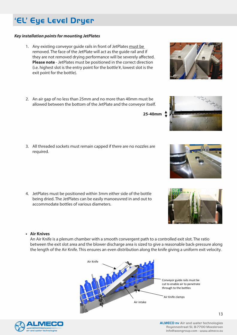
Key installation points for mounting JetPlates
1. Any existing conveyor guide rails in front of JetPlates must be removed. The face of the JetPlate will act as the guide rail and if they are not removed drying performance will be severely affected. Please note - JetPlates must be positioned in the correct direction (i.e. highest slot is the entry point for the bottle’#, lowest slot is the exit point for the bottle).
2. An air gap of no less than 25mm and no more than 40mm must be allowed between the bottom of the JetPlate and the conveyor itself.
3. All threaded sockets must remain capped if there are no nozzles are required.
4. JetPlates must be positioned within 3mm either side of the bottle being dried. The JetPlates can be easily manoeuvred in and out to accommodate bottles of various diameters.
ACI’s ‘EL’ DRI-Line Series www.bottlecandrying.com
Key installation points for mounting JetPlates
1. Any existing conveyor guide rails in front of
JetPlates must be removed. The face of the JetPlate will act as the guide rail and if they are not removed drying performance will be severely affected. Please note - JetPlates must be positioned in the correct direction (i.e. highest slot is the entry point for the bottle’#, lowest slot is the exit point for the bottle).
2. An air gap of no less than 25mm and no more than 40mm must be allowed between the bottom of the JetPlate and the conveyor itself.
3. All threaded sockets must remain capped if there are no nozzles are required.
4. JetPlates must be positioned within 3mm either side of the bottle being dried. The JetPlates can be easily manoeuvred in and out to accommodate bottles of various diameters.
ACI Air Knives An Air Knife is a plenum chamber with a smooth convergent path to a controlled exit slot. The ratio between the exit slot area and the blower discharge area is sized to give a reasonable back-pressure along the length of the Air Knife. This ensures an even distribution along the knife giving a uniform exit velocity.
25-40mm
Air Knife
Air intake
Conveyor guide rails must be cut to enable air to penetrate through to the bottles
Air Knife clamps
• Air KnivesAn Air Knife is a plenum chamber with a smooth convergent path to a controlled exit slot. The ratio between the exit slot area and the blower discharge area is sized to give a reasonable back-pressure along the length of the Air Knife. This ensures an even distribution along the knife giving a uniform exit velocity.
25-40mm
14
ALMECO nv Air and water technologiesRoyennestraat 51, B-7700 [email protected] - www.almeco.eu
‘EL’ Eye Level Dryer
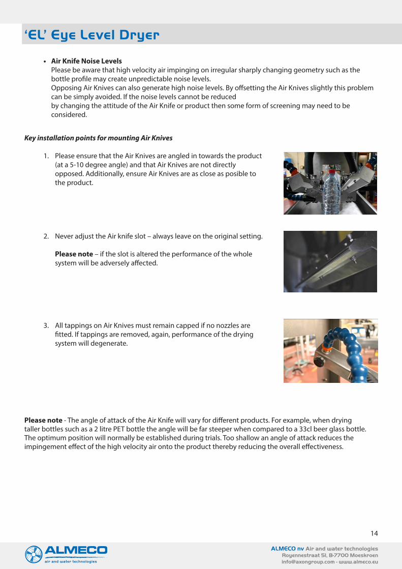
Key installation points for mounting Air Knives
1. Please ensure that the Air Knives are angled in towards the product (at a 5-10 degree angle) and that Air Knives are not directly opposed. Additionally, ensure Air Knives are as close as posible to the product.
2. Never adjust the Air knife slot – always leave on the original setting. Please note – if the slot is altered the performance of the whole system will be adversely affected.
3. All tappings on Air Knives must remain capped if no nozzles are fitted. If tappings are removed, again, performance of the drying system will degenerate.
• Air Knife Noise LevelsPlease be aware that high velocity air impinging on irregular sharply changing geometry such as the bottle profile may create unpredictable noise levels.Opposing Air Knives can also generate high noise levels. By offsetting the Air Knives slightly this problem can be simply avoided. If the noise levels cannot be reducedby changing the attitude of the Air Knife or product then some form of screening may need to be considered.
ACI’s ‘EL’ DRI-Line Series www.bottlecandrying.com
Air Knife Noise Levels
Please be aware that high velocity air impinging on irregular sharply changing geometry such as the bottle profile may create unpredictable noise levels. Opposing Air Knives can also generate high noise levels. By offsetting the Air Knives slightly this problem can be simply avoided. If the noise levels cannot be reduced by changing the attitude of the Air Knife or product then some form of screening may need to be considered.
Key installation points for mounting Air Knives
1. Please ensure that the Air Knives are angled in
towards the product (at a 5-10 degree angle) and that Air Knives are not directly opposed. Additionally, ensure Air Knives are as close as posible to the product.
2. Never adjust the Air knife slot – always leave on
the original setting. Please note – if the slot is altered the performance of the whole system will be adversely affected.
3. All tappings on Air Knives must remain capped if no nozzles are fitted. If tappings are removed, again, performance of the drying system will degenerate.
Please note - The angle of attack of the Air Knife will vary for different products. For example, when drying taller bottles such as a 2 litre PET bottle the angle will be far steeper when compared to a 33cl beer glass bottle. The optimum position will normally be established during trials. Too shallow an angle of attack reduces the impingement effect of the high velocity air onto the product thereby reducing the overall effectiveness.
Please note - The angle of attack of the Air Knife will vary for different products. For example, when drying taller bottles such as a 2 litre PET bottle the angle will be far steeper when compared to a 33cl beer glass bottle. The optimum position will normally be established during trials. Too shallow an angle of attack reduces the impingement effect of the high velocity air onto the product thereby reducing the overall effectiveness.

15
ALMECO nv Air and water technologiesRoyennestraat 51, B-7700 [email protected] - www.almeco.eu
‘EL’ Eye Level Dryer
• Can Drying TunnelsA Can Drying Tunnel is an enclosure that sits over the existing conveyor line. Contained within the enclosure is a plenum with a “Y” shaped exit slot, this parts liquid held in the can recess and pushes it off. The ratio between the exit slot area and the blower discharge area is sized to give a reasonable back-pressure within the plenum. This ensures an even distribution, giving a relatively uniform exit velocity.
• Noise LevelsHigh velocity air impinging on irregular sharply changing geometry can create high noise levels.
• MountingThe Can Drying Tunnel should be mounted such that at the tunnels lowest height setting, the shortest can is dried effectively (5-10mm above the can). The Can Drying Tunnel will sit directly over the line and allow existing guide rails to stay intact without modification. The Can Drying Tunnel can be raised / lowered to suit various sizes of product by adjustment of the latching handles located at either end, allowing use on multi sized product conveyors.
• InstallationUn-pack the containers and check off the components against the delivery notes. See the following diagrammatic instruction for an illustrated installation guide for Can Drying Tunnel Systems.
ACI’s ‘EL’ DRI-Line Series www.bottlecandrying.com
ACI Can Drying Tunnels A Can Drying Tunnel is an enclosure that sits over the existing conveyor line. Contained within the enclosure is a plenum with a "Y" shaped exit slot, this parts liquid held in the can recess and pushes it off. The ratio between the exit slot area and the blower discharge area is sized to give a reasonable back-pressure within the plenum. This ensures an even distribution, giving a relatively uniform exit velocity.
Noise Levels
High velocity air impinging on irregular sharply changing geometry can create high noise levels.
Mounting The Can Drying Tunnel should be mounted such that at the tunnels lowest height setting, the shortest can is dried effectively (5-10mm above the can). The Can Drying Tunnel will sit directly over the line and allow existing guide rails to stay intact without modification. The Can Drying Tunnel can be raised / lowered to suit various sizes of product by adjustment of the latching handles located at either end, allowing use on multi sized product conveyors.
Installation Un-pack the containers and check off the components against the delivery notes. See the following diagrammatic instruction for an illustrated installation guide for Can Drying Tunnel Systems.
Height adjustment bar
Can Drying Tunnel Enclosure Air intake
Inspection hatch
Brackets – directly attached to conveyor
16
ALMECO nv Air and water technologiesRoyennestraat 51, B-7700 [email protected] - www.almeco.eu
ACI’s ‘EL’ DRI-Line Series www.bottlecandrying.com
Installing Cap Dryers
ACI’s Cap Dryer is a small manifold with a fixed array of nozzles, allowing air to blast liquid off the product (see Fig 5.) If the cap area is required to be dried, a cap drying unit will need to have been supplied.
Noise Levels:
Please note that high velocity air impinging on irregular sharply changing geometry may create high noise levels.
Spray shield
Adjustable height adjuster
Fixed array of 8 nozzles
Air inlet
Mounting Brackets
‘EL’ Eye Level Dryer
• Installing Cap DryersThe Cap Dryer is a small manifold with a fixed array of nozzles, allowing air to blast liquid off the product (see Fig 5.) If the cap area is required to be dried, a cap drying unit will need to have been supplied.
• Noise LevelsPlease note that high velocity air impinging on irregular sharply changing geometry may create high noise levels.
ACI’s ‘EL’ DRI-Line Series www.bottlecandrying.com
Installing Cap Dryers
ACI’s Cap Dryer is a small manifold with a fixed array of nozzles, allowing air to blast liquid off the product (see Fig 5.) If the cap area is required to be dried, a cap drying unit will need to have been supplied.
Noise Levels:
Please note that high velocity air impinging on irregular sharply changing geometry may create high noise levels.
Spray shield
Adjustable height adjuster
Fixed array of 8 nozzles
Air inlet
Mounting Brackets

17
ALMECO nv Air and water technologiesRoyennestraat 51, B-7700 [email protected] - www.almeco.eu
‘EL’ Eye Level Dryer
• MountingThe Cap Dryer is supplied with a set of mounting brackets which can be directly attached to the conveyor (fixings are not supplier). The Cap Dryer should be mounted so that the slots of the dryer are in line with, and close to, the neck of the bottle being dried. The Cap Dryer is designed to fit over the guide bars sono modification of these is required.The Cap Dryer can be moved to suit various sizes of product by adjustment of the mounting brackets.
• InstallationUnpack the containers and check off the components against the deliverynotes. For a full diagrammatic instruction for an illustrated installation guide for the Cap Dryer.
• CommissioningAlmeco recommend employing experienced staff for the installation, assembly and start-up of the unit. Almeco cannot be held responsible for damage or defects caused by self- directed poor installation, assembly or start-up of the unit.
Installation and commissioning procedures should be carried out by an expert in compliance with local accident prevention regulations.
ACI’s ‘EL’ DRI-Line Series www.bottlecandrying.com
Mounting:
The Cap Dryer is supplied with a set of mounting brackets which can be directly attached to the conveyor (fixings are not supplier). The Cap Dryer should be mounted so that the slots of the dryer are in line with, and close to, the neck of the bottle being dried. The Cap Dryer is designed to fit over the guide bars so no modification of these is required. The Cap Dryer can be moved to suit various sizes of product by adjustment of the mounting brackets.
Installation: Unpack the containers and check off the components against the delivery notes. For a full diagrammatic instruction for an illustrated installation guide for the Cap Dryer.
Commissioning
ACI recommend employing experienced staff for the installation, assembly and start-up of the unit. ACI cannot be held responsible for damage or defects caused by self-directed poor installation, assembly or start-up of the unit. Installation and commissioning procedures should be carried out by an expert in compliance with local accident prevention regulations.

18
ALMECO nv Air and water technologiesRoyennestraat 51, B-7700 [email protected] - www.almeco.eu
‘EL’ Eye Level Dryer
4. TECHNICAL DATA AND EL MATERIALS Type
Machine Number:
Year of Manufacture:
Standard voltage:
Motor type:
Motor power:
Materials:
DRI-Line Series – ‘EL’ Eye Level Model
Refer to Serial Number on Motor Label
Refer to Date on Motor Label
380/420VY / 660-690Y 3Ph 50Hz440-480D 3Ph 60HzPlease note (other voltages are available for this unit)
Induction type / TEFC / IP55
7.5/11 or 15kW
• All of the stainless steel used throughout the EL DRI-Line Series is 304.• EP10A Blower materials:
• Motor – Alumunium• Blower head and mounting bracket – Alumunium Alloy LM25• Spindle Assembly – Steel EN40B• Belt Guard – ABS Plastic• Belt – Rubber compound
19
ALMECO nv Air and water technologiesRoyennestraat 51, B-7700 [email protected] - www.almeco.eu
‘EL’ Eye Level Dryer
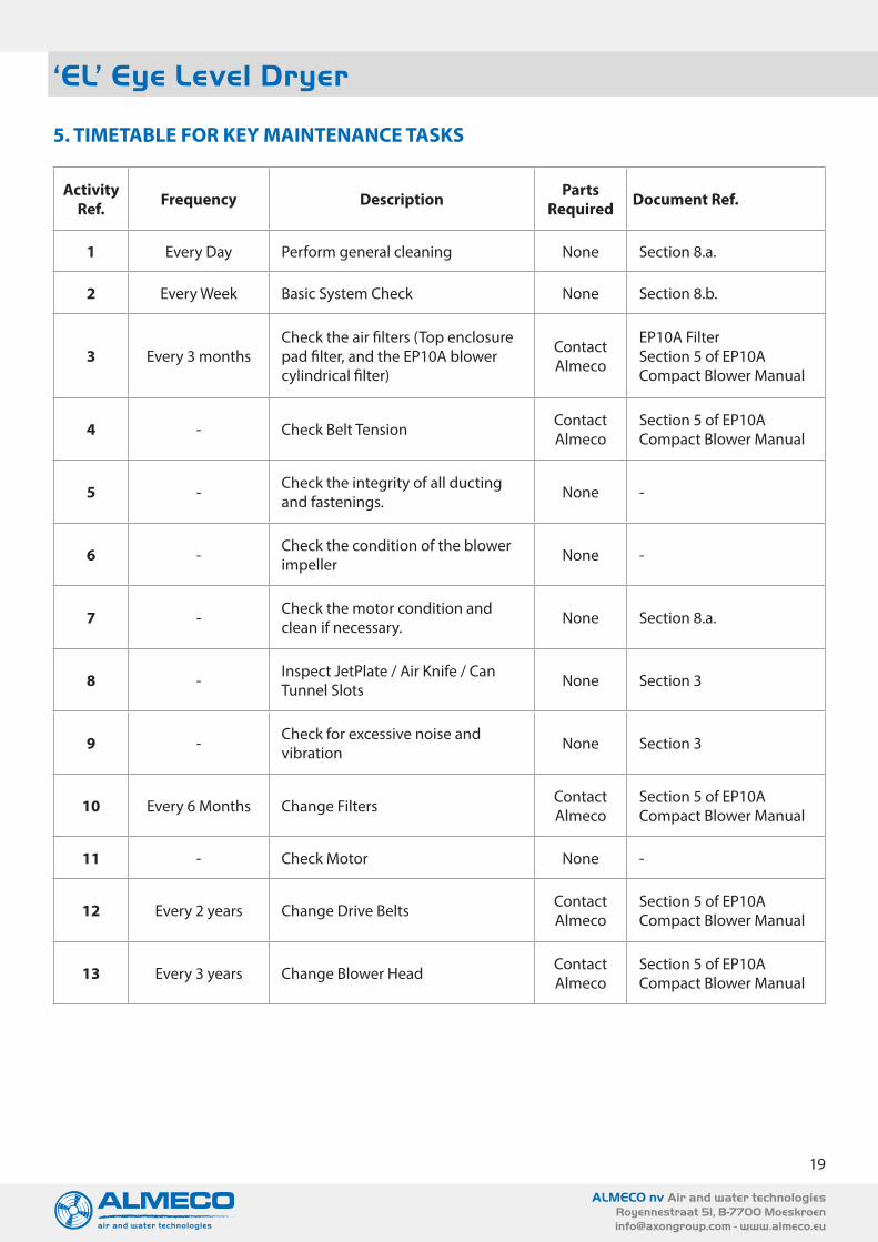
5. TIMETABLE FOR KEY MAINTENANCE TASKS
Activity Ref. Frequency Description Parts
Required Document Ref.
1 Every Day Perform general cleaning None Section 8.a.
2 Every Week Basic System Check None Section 8.b.
3 Every 3 monthsCheck the air filters (Top enclosure pad filter, and the EP10A blower cylindrical filter)
Contact Almeco
EP10A FilterSection 5 of EP10A Compact Blower Manual
4 - Check Belt Tension Contact Almeco
Section 5 of EP10A Compact Blower Manual
5 - Check the integrity of all ducting and fastenings. None -
6 - Check the condition of the blower impeller None -
7 - Check the motor condition and clean if necessary. None Section 8.a.
8 - Inspect JetPlate / Air Knife / Can Tunnel Slots None Section 3
9 - Check for excessive noise and vibration None Section 3
10 Every 6 Months Change Filters Contact Almeco
Section 5 of EP10A Compact Blower Manual
11 - Check Motor None -
12 Every 2 years Change Drive Belts Contact Almeco
Section 5 of EP10A Compact Blower Manual
13 Every 3 years Change Blower Head Contact Almeco
Section 5 of EP10A Compact Blower Manual

20
ALMECO nv Air and water technologiesRoyennestraat 51, B-7700 [email protected] - www.almeco.eu
6. GENERAL OPERATION INFORMATION
a. General safety statement
If any adjustment to the EL unit is required electrically isolate the blower before commencing work.
When operating the EL DRI-Line Drying System, always wear:
• Eye protection• Ear protection• Safety footwear
Never:
• Run the blower unit without the belt guard fitted• Run the blower when disconnected from the JetPlate/Air Knife/Can Tunnel arrangement.
Always ensure:
• The power is isolated and locked off before commencing any maintenance on the system.• Before operating the system ensure that the EL unit is secured in position.• Any access covers or guards have not been removed. These items should only be removed if the
EP10A compact blower is stationary and isolated from the electrical supply.• All filters are regularly cleaned and replaced.
b. EL Start upApart from the EP10A Blower which is sited in the top enclosure, there are no moving parts in the EL unit. Therefore the EL unit can be started via a plc or a star/delta starter or an inverter depending on which has been fitted. Ensure JetPlates/ Air Knives / Can Tunnel are set correctly
Please note – Generally, it is not Almeco’s responsibility to ensure control of start/stop. Additionally, if star/delta starting is switched by a plc, it is not Almeco’s responsibility to ensure timings are correct.
c. EL Shut Down• The EP10A blower should be stopped via a plc, star/delta starter or an inverter.• The blower is designed to be continuously run and therefore stop/start cycles should be kept to a
minimum. 6 (Six) per hour is the maximum level recommended by Almeco.• If linked to the conveyor line, there should be a timer delay fitted to avoid too many stop/starts. If this is
not adhered to, damage to the EP10A blower belt and head assembly will occur.
Please note - Almeco is generally not responsible for the fitting of any isolators and emergency stops.
Stop/Start cycles must be kept to a minimum – 6 (six) per hour is the maximum amount recommended.
‘EL’ Eye Level Dryer

21
ALMECO nv Air and water technologiesRoyennestraat 51, B-7700 [email protected] - www.almeco.eu
d. Adjustment / Maintenance
If any adjustment to the EL unit is required electrically isolate the blower before commencing work.
i. JetPlates• Loosen fixing handles and adjust accordingly (see Figure 6).• Take 3 bottles of size required• Place one either end and one in middle of JetPlate• Face of JetPlates should be a within 3mm of the sides of bottles (see Figure 7)• Re-tighten fixing handles
JetPlates require little maintenance. However, some important points are as follows:• Blocked JetPlate slots can be cleaned as necessary using a non-metallic tool to remove blockages as
this can result in damage to the JetPlate. Please note - never allow liquid to pass into the plenum and therefore into the blower.
• If threaded blanking plugs have been fitted to JetPlates, never remove them unless replacing with a flexible nozzle.
• There must always be an air gap of 25-40mm between the bottom of the JetPlate and the conveyor.
ii. Air KnivesIn order to operate effectively, and efficiently, it is paramount that the Air Knives are positioned, and remain positioned correctly. Ignoring this instruction may lead to a noticeable loss of performance.
Correct Air knife Positioning when used in conjunction with JetPlates:
Air Knives require little maintenance. However, some important points are as follows:• Blocked Air Knife slots can be cleaned as necessary using a non-metallic tool to remove blockages as
this can result in damage to the Air Knife. Please note - never allow liquid to pass into the plenum and therefore into the blower.
• If threaded blanking plugs have been fitted to Air Knives, never remove them unless replacing with a flexible nozzle.
‘EL’ Eye Level Dryer
JetPlate Mounting Bracket JetPlate Positioning
ACI’s ‘EL’ DRI-Line Series www.bottlecandrying.com
d. Adjustment /Maintenance
i. JetPlates Loosen fixing handles and adjust accordingly (see Figure 6). Take 3 bottles of size required Place one either end and one in middle of JetPlate Face of JetPlates should be a within 3mm of the sides of bottles (see Figure 7) Re-tighten fixing handles
JetPlate Mounting Bracket JetPlate Positioning
JetPlates require little maintenance. However, some important points are as follows: Blocked JetPlate slots can be cleaned as necessary using a non-metallic tool to remove blockages as
this can result in damage to the JetPlate. Please note - never allow liquid to pass into the plenum and therefore into the blower.
If threaded blanking plugs have been fitted to JetPlates, never remove them unless replacing with a flexible nozzle.
There must always be an air gap of 25-40mm between the bottom of the JetPlate and the conveyor.
ii. Air Knives In order to operate effectively, and efficiently, it is paramount that ACI Air Knives are positioned, and remain positioned correctly. Ignoring this instruction may lead to a noticeable loss of performance. Correct Air knife Positioning when used in conjunction with JetPlates:
The angle of the Air Knife is completely bottle dependant. For example, when drying taller bottles such as a 2 litre PET bottle the angle will be far steeper when compared to a 33cl beer glass bottle.
Also note, that the Air Knives should be turned in towards the conveyor at an
angle of 5-10 degrees. Air Knives require little maintenance. However, some important points are as follows:
Blocked Air Knife slots can be cleaned as necessary using a non-metallic tool to remove blockages as this can result in damage to the Air Knife. Please note - never allow liquid to pass into the plenum and therefore into the blower.
If threaded blanking plugs have been fitted to Air Knives, never remove them unless replacing with a flexible nozzle.
If any adjustment to the EL unit is required electrically isolate the blower before commencing work.
The angle of the Air Knife is completely bottle dependant. For example, when drying taller bottles such as a 2 litre PET bottle the angle will be far steeper when compared to a 33cl beer glass bottle.
Also note, that the Air Knives should be turned in towards the conveyor at an angle of 5-10 degrees.

22
ALMECO nv Air and water technologiesRoyennestraat 51, B-7700 [email protected] - www.almeco.eu
iii. Can Drying TunnelsCan Tunnels require very little maintenance. However, the following points should be noted if the DRI-Line System’s performance reduces:
• Blocked inlet filter on the blower (please refer to the EP10A Compact Blower Manual)• Blocked Can Drying Tunnel Slots
If either occurs, always switch off the air supply, and isolate the blower. Then:• Check the Can Tunnel is set to the correct height (i.e. 5 to 10mm above the can). Also check the
cans are passing through the tunnel in the right direction.• Reduced Flow: Dis-connect the hose from the tunnel inlet, remove the mounting screws and
remove the tunnel from the conveyor.• To remove blockages open the front of the plenum by removing the screws around the edge of
the slot plate
iv. Cap DryerThese units require little maintenance other than regular cleaning. General inspection of flexible hose and routine cleaning will be required only.
v. EP10A Compact BlowerTo carry out any adjustments to the EP10A blower (i.e. Belts, Filters) please refer to separate EP10A Compact Blower Manual
vi. Ducting and clampingAll ducting and clamping can be easily adjusted if necessary. All fitted jubilee clips can be adjusted using a standard size flat-headed screwdriver.
e. Vibration and Noisei. Enclosure
Work related emission value is <85dB(A) during idle operation. If noise levels below this are required, specific sound reduction equipment may be supplied at an extra cost. If further information is required please contact Almeco directly.
ii. EP10A Blower / Filter Units (Please refer to EP10A Manual for further details)Due to the nature of the drying equipment noise emissions from the EP10A Blower will always be present during normal working conditions. This is due to the high speed rotational characteristics of the unit (the EP10A Blower can generate speeds of 20,000 rpm).
If there is either excessive vibration and/or noise from the EP10A Blower, the following procedures must be followed:
• Electrically isolate the blower.• Remove top enclosure panels to access the blower (requires the key which is supplied).• Remove the belt guard using 4mm Hexagon key.• Check the tension on the belt using the supplied Krikit gauge located on the mounting plate.• Additionally, check the belt for fraying and general wear and tear.• If the belt is in any way damaged, change it immediately. Do not operate the blower until a new belt is
fitted and the belt guard refitted.
If the EP10A blower is showing a reduced performance:• Electrically isolate the blower.• Remove the top enclosure panels so the blower motor and cylindrical filter are visible.• Remove and replace filter element. See the following section for further information.• Briefly apply power to the blower to check the rotation of the motor. The direction of the motor
cooling fan should be as per the arrow (anti clockwise) viewed non drive end.
‘EL’ Eye Level Dryer

23
ALMECO nv Air and water technologiesRoyennestraat 51, B-7700 [email protected] - www.almeco.eu
‘EL’ Eye Level Dryer
Incorrect fan rotation is the most common cause of drying system under performance. Double check!
It is essential that air filters are regularly maintained and replaced.
7. MALFUNCTION-CAUSE-REMEDY
Please Note – any references to the EP10A blower, please refer to the EP10A Manual for further details.
Malfunction Possible Cause Remedy
Low flow, Low Pressure
Incorrect blower rotation. Check and correct blower rotation if required
Dirty or contaminated filters.These items MUST be changed regularly (minimum of 6 months) dependant on amount of use.
Damaged hose lining. Replace damaged hose.
Air leaks in system. Check / replace damaged hose and clips.
Drive belt slipping/Worn Pulley Replace transmission parts.
Incorrect speed from control system. Check inverter / soft start / star delta settings.
Unapproved drive belts being fitted Replace existing drive belt with Almeco approved belt.
Closed or damaged valve Check valve and replace if damaged.
High flow, Low Pressure
Blower speed too high for application.
Reduce blower speed by using inverter or reducing pulley size.
Operating frequency too high – maximum head speed must not exceed 20,000 rpm.
Check design frequency and reduce by inverter or change pulley size.
Frequent EP10A DriveBelt Failure
Incorrect belt tension Check belt tension and correct if necessary.
Motor pulley out of alignment Check pulley alignment and correct if necessary.
Pulley grooves worn Replace transmission parts.
Hostile environment (belts contaminated)
Replace belt, clean pulleys and protect blower from hostile environment.
Incorrect belt fitted. Replace existing belt with the approved belt.
Incorrect belt installation method (Rolling belts onto pulleys)
Read EP10A manual for correct installation and do not roll belts.
Liquid entering blower inlet Isolate blower from any source of liquid.
Incorrect starting ramp time
If an inverter is used, a 4 second ramp up time is recommended. If a star/delta timer is used ensure there is no delay between switching from star to delta.
Too many stop/startsAvoid high number of stop starts (a maximum of 6 per hour) unless using a frequency inverter. Suggested minimum inverter setting = 30Hz.

24
ALMECO nv Air and water technologiesRoyennestraat 51, B-7700 [email protected] - www.almeco.eu
‘EL’ Eye Level Dryer
Electrical Overloading
Blower exceeding rated CFM Reduce ‘open area’ of air delivery devices – i.e. slot width of Air Knives.
Blower not piped to system correctly.
Only run blower when connected to the operating system. Never run in isolation.
Blower RPM too high Reduce blower speed via inverter or change pulley size.
Motor has winding or bearing damage Contact Almeco immediately.
Electrical supply problems Ensure that supply voltages match with the motor rating plate details.
Leak in air delivery ducting Replace any damaged ducting
Irregular/ExcessiveNoise
Blockage in air delivery ducting Check all ducting and air delivery devices for blockages/damage. Replace as necessary.
Leak in air delivery ducting Check and replace damaged hose and clips.
Inlet silencer damaged (internally) Replace main EP10A filter housing.
Loose drive belt Check belt tension and correct if necessary.
Bolts loose on blower/motor assembly
Regular maintenance and checking/tightening all bolts.
Motor mounts loose Regular maintenance and checking/tightening all mounts.
Blower bearings worn Contact Almeco immediately.
Motor bearings worn Contact Almeco immediately.
Blower RPM too high Reduce blower speed via inverter or change pulley size.
Reduced DryingEfficiency / Airflow
Blocked inlet filter on the blower Inspect the inlet filter on the blower and the enclosure. Clean or replace as necessary.
Blocked JetPlates slots/nozzles
Check and clean if necessary all slots and nozzles of the system. Do not use a metal tool to remove blockages as this can result in damage. Also, never allow liquid to pass into the plenum and thereforeonto the blower.
Poor adjustment or installation settings, for example:
• Not cutting guide rails when installing JetPlates
• Not allowing for 25mm / 40mm air gap between JetPlates and conveyor
• Removal of fitted plugs for nozzles
Please refer to ‘Installation Guide’.
25
ALMECO nv Air and water technologiesRoyennestraat 51, B-7700 [email protected] - www.almeco.eu
‘EL’ Eye Level Dryer
8. CLEANING AND INSPECTION
• Cleaning:
The unit requires very little maintenance. However, always electrically isolate the blower before commencing any maintenance.
Most components of the EL Drying unit can all regularly jet washed/cleaned. However, areas that must not be cleaned directly are:
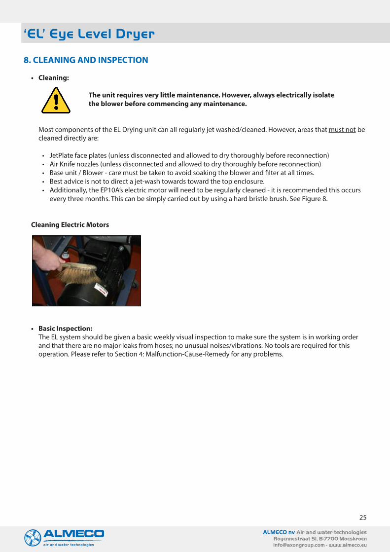
• JetPlate face plates (unless disconnected and allowed to dry thoroughly before reconnection)• Air Knife nozzles (unless disconnected and allowed to dry thoroughly before reconnection)• Base unit / Blower - care must be taken to avoid soaking the blower and filter at all times.• Best advice is not to direct a jet-wash towards toward the top enclosure.• Additionally, the EP10A’s electric motor will need to be regularly cleaned - it is recommended this occurs
every three months. This can be simply carried out by using a hard bristle brush. See Figure 8.
Cleaning Electric Motors
• Basic Inspection:The EL system should be given a basic weekly visual inspection to make sure the system is in working order and that there are no major leaks from hoses; no unusual noises/vibrations. No tools are required for this operation. Please refer to Section 4: Malfunction-Cause-Remedy for any problems.
ACI’s ‘EL’ DRI-Line Series www.bottlecandrying.com
8. CLEANING AND INSPECTION
Cleaning:
Most components of the EL Drying unit can all regularly jet washed/cleaned. However, areas that must not be cleaned directly are:
JetPlate face plates (unless disconnected and allowed to dry thoroughly before reconnection) Air Knife nozzles (unless disconnected and allowed to dry thoroughly before reconnection) Base unit / Blower - care must be taken to avoid soaking the blower and filter at all times.
Best advice is not to direct a jet-wash towards toward the top enclosure. Additionally, the EP10A’s electric motor will need to be regularly cleaned - it is
recommended this occurs every three months. This can be simply carried out by using a hard bristle brush. See Figure 8.
Cleaning Electric Motors
b. Basic Inspection:
The EL system should be given a basic weekly visual inspection to make sure the system is in working order and that there are no major leaks from hoses; no unusual noises/vibrations. No tools are required for this operation. Please refer to Section 4: Malfunction-Cause-Remedy for any problems.
EL Units require very little maintenance. However, always electrically isolate the blower before commencing any maintenance.

26
ALMECO nv Air and water technologiesRoyennestraat 51, B-7700 [email protected] - www.almeco.eu
‘EL’ Eye Level Dryer
9. WARRANTY
Air Control Industries Limited (ACI) warrants all products manufactured by ACI to be free of defects in material and workmanship for eighteen (18) months from the date of shipment.
The warranty does not apply to drive belts, filter elements or connecting hose, unless authorised by an officer of ACI. Also, not covered under the warranty is normal wear and tear, neglect or misuse of the equipment, operation in an application not approved by ACI, and alterations not performed by ACI.
All items supplied by ACI that are manufactured by others shall be warranted under the respective manufacturer’s policy. Motors and other items, for which a national service network is in place, should be sent directly to that manufacturer’s representative for the most prompt service. ACI will provide any support required ensuring that warranty service by others in handled in a prompt and professional manner.
The ACI warranty is limited to the repair or replacement of items shipped by ACI. At no time will ACI be liable for any of the costs to the buyer for labour, transportation or down-time resulting from defective equipment furnished by ACI, or Almeco. Warranty will be void unless the blower head is returned complete.
It is recommended that in critical applications, a spare unit head assembly is purchased and kept as a spare part. ACI offers a ‘service exchange’ programme on both the complete blower head assembly and the spindle assembly. Contact ACI for prices. Upon receipt, ACI will inspect the failed unit and quote for the repair. A repair unit will be shipped from stock on receipt of an official purchase order. The customer’s own blower unit will be repaired for all warranty claims.

PCA
[email protected] www.pcawater.comwww.pcacontrol.comwww.pca-air.com
ALMECO
PCA Main officePCA NV Wijngaardveld 10 B-9300 Aalst+32 (0)53 21.33.55
Almeco Belgium (HQ)ALMECO NV Royennestraat 51 B-7700 Moeskroen+32 (0)56 85.40.80
OUR BUSINESS UNITS:
• industrial fans• fluid cooling systems• drying solutions• water treatment• air treatment• automation
PCA Regional officePCA NV Royennestraat 51 B-7700 Moeskroen+32 (0)56 55.00.90
Almeco The NetherlandsALMECO NEDERLAND BV Postbus 32 NL-5550 AA Valkenswaard+31 (0)40 80.80.000
Almeco FranceALMECO FRANCE SARLRue de Luxembourg 67 FR-59777 Euralille+33 (0)3 28.48.26.68