installation, operation, maintenance and parts manual
TRANSCRIPT
FT-C Vertical Electric Thermal Fluid Heater Manual 12 2013 ISSUE 1
Fulton Ltd
FT-C Fuel Fired Thermal Fluid Heater
This Manual must be available to the heater operator at all times.
INSTALLATION, OPERATION, MAINTENANCEAND PARTS MANUAL
FT-C Vertical Electric Thermal Fluid Heater Manual 12 2013 ISSUE 1
For your Safety!The following WARNINGS, CAUTIONS and NOTES appear in various sections of this manual.
WARNINGS must be observed to prevent serious injury or death to personnel.
CAUTIONS must be observed to prevent damage or destruction of equipment or loss of operating effectiveness.
NOTES: must be observed for essential and effective operating procedures, conditions and as a statement to be highlighted.
It is the responsibility and duty of all personnel involved in the operation and maintenance of this equipment to fully understand the WARNINGS, CAUTIONS and NOTES by which hazards are to be eliminated or reduced.
Personnel must become familiar with all aspects ofsafety and equipment prior to operation ormaintenance of the equipment.
WARNINGThermal Fluid Heaters are a potential hazard,
possibly fatal if not properly maintained.
CAUTIONIt is vitally important that the instructions given in this manual are strictly adhered to. Failure to carry
out the routine maintenance checks could result in a drastic reduction in the
life expectancy of the system, fire, explosion, property damage, personal injury or loss of life.
!
!
!
!
WARNINGDo not try to do repairs or any other maintenance work you
do not understand. Obtain a Service Manual from Fulton Ltd or call a Fulton Service Engineer.
WARNINGIt is the responsibility of the installer to ensure all parts supplied with the boiler are fitted in a correct and safe manner.
SAFETY The instructions provided for the operation and maintenance of the system MUST be observed. Failure to do so could result in damage to the boiler and serious personal injury.
!
SAFETY WARNINGS AND PRECAUTIONS
Prior to shipment, the following tests are made to assure the customer the highest standards of manufacturing:
a) Material inspectionsb) Manufacturing process inspectionsc) ASME welding inspection d) ASME hydrostatic test inspection e) Electrical components inspection f) Operating testg) Final engineering inspection h) Crating inspection
Rigging your heater into position should be handled by a competent rigger experienced in handling heavy equipment.
The customer should examine the heater for any damage, especially the refractories. It is the responsibility of the installer to ensure all parts supplied with the heater are fitted in a correct and safe manner.
! WARNINGUnderstand the electrical circuit before connecting or
disconnecting an electrical component. A wrong connection can cause injury and or damage.
WARNINGA defective heater can injure you or others. Do not operate
a which is defective or has missing parts. Make surethat all maintenance procedures are completed before usingthe system. Do not attempt repairs or any other maintenance work you do not understand. Obtain a Service Manual from
Fulton or call a Fulton Service Engineer.
!!
- WHAT TO DO IF YOU SMELL GAS• Do not try to light any appliance.• Do not touch any electrical switch; do not use any phone in your building.• Immediately call your gas supplier from a neighbor’s phone. Follow the gassupplier’s instructions.• If you cannot reach your gas supplier, call the fire de-partment.
!
FT-C Vertical Electric Thermal Fluid Heater Manual 12 2013 ISSUE 1
CAUTIONDuring operation, any leaks are usually detected by a small
amount of vapour. Leaks should be attended to as soon as possible because under certain circumstances, such as saturated insulation, thermal fluid can ignite when exposed
to air and heat.
Note: Fulton Ltd cannot be held responsible in the case of accident or damage resulting from the use of inadequate fluid.
Note: Unless specially filtered, compressed air will introduce moisture into the system. Dry air or Nitrogen is recommended.
Note: Some plastics can be dissolved by thermal fluid.
Note: Do not use system circulating pump for system filling.
Note: A pump that has been used for water or for a different thermal fluid should not be used prior to extensive cleaning. Thermal fluid can be damaged by contact with moisture or other fluids.
WARNINGPressurising a drum to force fluid into the system is not recommended. The drum can easily explode, creating a
hazard to personnel and equipment.
Note: Tanks are non-code as a standard. Non-code tanks cannot be pressurised over 0.5 barg. Tanks built to BS EN13445:2009 are available upon request.
Note: Do not run the pump before filling it with fluid.
CAUTION1. Use extreme caution opening plug when system
temperature is elevated.
2. Wear eye and hand protection.
3. Back the plug out slowly to the last two or three threads.Allow any pressure under the plug to bleed slowly to prevent a spray of hot oil.
Note: Flash steam may be generated at any point up to the operating temperature. Watch for gauge fluctuations.
Note: All of the above maintenance procedures should be completed by trained personnel. Appropriate training and instructions are available from the Fulton Service Department.
CAUTIONObey all laws and local regulations which affect you and
your boiler.
WARNINGLIFTING EQUIPMENT
Make sure that lifting equipment complies with all local regulations and is suitable for the job. You can be injured if you use faulty lifting equipment. Make sure the lifting
equipment is in good condition.
WARNINGOperating the heater beyond its design limits can damage the heater, it can also be dangerous. Do not operate the heater outside its limits. Do not try to upgrade the heater performance by unapproved modifications. Unapproved modifications can cause injury and damage. Contact your Fulton dealer before
modifying the heater.
WARNINGOnly qualified persons should be allowed to operate and
maintain the boiler and its equipment.
WARNINGDo not store or use gasoline or other flammable vapours and liquids in the vicinity of this or any other appliances.
WARNINGDANGER FROM HOT SURFACES
Thermal Fluid Heaters have high temperature surfaces, that if touched may cause serious burns. Only competent and qualified personnel should work on or in the locality of a thermal fluid heater and ancillary equipment. Always ensure the working area and floor are clear of potential hazards,
work slowly and methodically.
Note: Max. room temperature not to exceed 38 °C.
Note: In no case should any part of the drive side of the pump be insulated.
Note: Max. operating temperature for air cooled pumps varies by manufacturer. Consult instruction manual to verify.
Note: If the tank is located outdoors nitrogen is required.
WARNINGHigh temperature thermal fluid, steam and combustible
vapours may be vented through the DA vent connection.
WARNINGOnce the system has been filled, any modification to the
tank or connected piping requires purging of the work area to prevent ignition of potentially flammable vapours. Consult
factory prior to beginning work. Consult the MSDS (mate-rial data safety sheet) for your thermal fluid for flammability
limits.
Note: Unless the system is pressurised, the inlet to the deaerator section of the combonation tank must be higher than or equal to the highest point in the system to prevent pockets of air from collecting in the system piping.
!
!
!
!
!
!
!
!
!
!
!
Note: If the burner loses flame while driving to a point then: • Turn the main ON/OFF switch to OFF. Reset the loss of flame fault. Press Escape on the AZL once. Press Enter on the AZL to reset the control. The red light on the panel box door should go out.• Adjust the air and gas servos for that point while the burner is off. Follow steps 28-29.• Turn the main ON/OFF switch to ON.
FT-C Vertical Electric Thermal Fluid Heater Manual 12 2013 ISSUE 1
TITLE SECTION
INTRODUCTION 1General 1.1Technical Data (Heat Output) 1.2
INSTALLATION 2General 2.1Transport 2.2Siting 2.3Gas & Oil Supply 2.4Oil Supply 2.5Access 2.6Minimum Clearance for Coil Removal 2.6.1System Connections 2.7Drain/Fill Connection 2.7.1Heater Connections 2.7.2Electrical Connections 2.7.3Voltage and Frequency 2.7.3.1Pipework Systems 2.8Combination Expansion/Deaerator/Thermal Buffer Tank 2.9Expansion Section 2.9.1Deaerator Section 2.9.2Thermal Buffer Section 2.9.3Sizing the Tank for the System 2.9.4Location 2.9.5Pressurised Systems 2.9.6Connections 2.9.7Oil and Gas Circulating Pump 2.10Location 2.10.1Connections and Piping 2.10.2Alignment 2.10.3Lubrication 2.10.4Seals 2.10.5Air Cooling 2.10.6Water Cooling 2.10.7Catch Tank 2.11Gauges 2.12Valves 2.13Piping 2.14Gasket Installation Instructions 2.15Testing 2.16Insulation 2.17Thermal Fluids 2.18Thermal Fluids at Elevated Temperatures 2.18.1Selecting a Thermal Fluid 2.18.2Routine Analysis of Heat Transfer Liquid 2.18.3Thermal Fluid Breakdown 2.18.4Multi-Skid Systems 2.19
OPERATION 3General 3.1Start-Up Preparation and Installation Review 3.2Filling the System 3.3Filling Procedure 3.3.1For Systems Equipped with Inert Blankets 3.4Circulating Pump 3.5Mechanical/Air Cooled Seal 3.5.1
LIST OF CONTENTS
FT-C Vertical Electric Thermal Fluid Heater Manual 12 2013 ISSUE 1
Initial Start-Up 3.6Start-Up Service 3.6.1Cold Circulation 3.6.2Filtering the System 3.6.3Sytem Boilout 3.6.4Procedure For First Shutdown 3.6.5Sequence of Operation 3.6.6Duel Fuel Burner-Changing Fuel 3.6.7Gas Fired Modulating Burner 3.6.8Setting Main Burner Ignition 3.6.9Setting Main Run Modulation 3.6.10Setting Low Fire 3.6.11Setting the Complete Range 3.6.12Changing Set Point on the AZL 3.6.13For Manual Operation 3.6.14Required Pressure Drop Across the Heater 3.7Required Flow Through the Heater 3.8Operating Controls 3.9Liquid Level Switch - When Combination Tank is Supplied 3.9.1Air Safety Switch 3.9.2Blower Motor Starter 3.9.3Differential Pressure Switch 3.9.4Pump Motor Starter 3.9.5High and Low Fluid Pressure Switches 3.9.6Gas Pressure Switch 3.9.7Operating Temperature Control 3.9.8High Limit Temperature Control 3.9.9Pressure Gauges 3.9.10Operating Limit Controller 3.9.11On/Off Controls 3.9.12Flow Proving Device 3.9.13Test Of Ignition Safety System Shutoff 3.9.14Cycle Testing 3.9.15Daily Start-Up 3.10Daily Shutdown 3.11
MAINTENANCE 4Required Maintenance at First Shutdown 4.1Maintenance Procedures 4.2Lubrication 4.2.1Soot Cleaning 4.2.2Schedule of Operator Tests and Checks 4.3Daily 4.3.1Weekly 4.3.2Monthly 4.3.3Six Monthly 4.3.4Annually 4.3.5Safety Check Procedures 4.4Temperature Limits 4.4.1Air Switch 4.4.2Air Filter Box Switch 4.4.2.1Liquid Level Switch 4.4.3Differential Pressure Switch 4.4.4Low Inlet Pressure Switch 4.4.5High Outlet Pressure Switch 4.4.6High/Low Gas Pressure Switch 4.4.7Troubleshooting 4.5Troubleshooting: Flow Circuit/Circulating Pump(s) 4.5.1
LIST OF CONTENTS
FT-C Vertical Electric Thermal Fluid Heater Manual 12 2013 ISSUE 1
LIST OF CONTENTS
Troubleshooting: Tripped High Outlet Pressure Switch 4.5.2Troubleshooting: Differential Pressure Switch Break 4.5.3Troubleshooting: Call for Heat 4.5.4Troubleshooting: Safety Interlock 4.5.5Maintenance Log 4.6
GENERAL DATA 5General Dimensions 5.1FT-C Specification 5.2Electrical Diagrams 5.3
FT-C Vertical Electric Thermal Fluid Heater Manual 12 2013 ISSUE 1
TITLE FIG. NO.
General Arrangement 1FT-C Component View 2CSD-I Fuel Train 3NFPA Fuel Train 4Oil Fired Fuel Train 5Drain and Fill Connection 6Thermal Fluid Heater Nameplate 7FT-L Expansion/Deaeration/Thermal Buffer Sections 8FT-L Combination Expansion/Deaerator/Thermal Buffer Tank 9Liquid Level Switch 10Oil and Gas Circulating Pump 11Typical Water Cooled Pump 12Pressure Gauges 13Typical Thermal Piping Shematic 14Bolting Seqeunce 4 and 8 Bolt Flanges 15Drain and Fill Connections 16Proper Fluid Level in Dearator Tank Expansion Section 17Oil Nozzle Dual Fuel Burner (FT-0400-C - FT-1400-C) 18Gas Nozzle with Orifice Dual Fuel Burner (FT-0400-C - FT-1400-C) 19Complete Dual Fuel Assembly 20Control Panel Fascia 21Electrical Panel 22Thermal Fluid Circulating Pump 23Pump Coupling 24Strainer 25Operating Temperature Control 26Differential Pressure Switch 28Inlet and Outlet Pressure Gauges 29High Outlet Pressure Switch 30Electrical Diagram: FT-C 0430 Electrical Thermal Fluid Heater On/Off 31
LIST OF ILLUSTRATIONS
FT-C Vertical Electric Thermal Fluid Heater Manual 12 2013 ISSUE 1
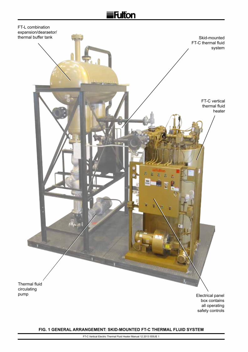
FT-C vertical thermal fluid
heater
Electrical panelbox containsall operating
safety controls
FT-L combination expansion/dearaetor/thermal buffer tank
Thermal fluidcirculating pump
Skid-mounted FT-C thermal fluid
system
FIG. 1 GENERAL ARRANGEMENT: SKID-MOUNTED FT-C THERMAL FLUID SYSTEM
FT-C Vertical Electric Thermal Fluid Heater Manual 12 2013 ISSUE 1 Page 1
1
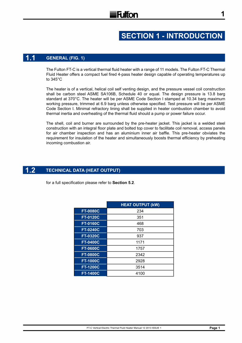
The Fulton FT-C is a vertical thermal fluid heater with a range of 11 models. The Fulton FT-C Thermal Fluid Heater offers a compact fuel fired 4-pass heater design capable of operating temperatures up to 345°C
The heater is of a vertical, helical coil self venting design, and the pressure vessel coil construction shall be carbon steel ASME SA106B, Schedule 40 or equal. The design pressure is 13.8 barg standard at 370°C. The heater will be per ASME Code Section I stamped at 10.34 barg maximum working pressure, trimmed at 6.9 barg unless otherwise specified. Test pressure will be per ASME Code Section I. Minimal refractory lining shall be supplied in heater combustion chamber to avoid thermal inertia and overheating of the thermal fluid should a pump or power failure occur.
The shell, coil and burner are surrounded by the pre-heater jacket. This jacket is a welded steel construction with an integral floor plate and bolted top cover to facilitate coil removal, access panels for air chamber inspection and has an aluminium inner air baffle. This pre-heater obviates the requirement for insulation of the heater and simultaneously boosts thermal efficiency by preheating incoming combustion air.
SECTION 1 - INTRODUCTION
1.1 GENERAL (FIG. 1)
1.2 TECHNICAL DATA (HEAT OUTPUT)
for a full specification please refer to Section 5.2.
HEAT OUTPUT (kW)FT-0080C 234FT-0120C 351FT-0160C 468FT-0240C 703FT-0320C 937FT-0400C 1171FT-0600C 1757FT-0800C 2342FT-1000C 2928FT-1200C 3514FT-1400C 4100
FT-C Vertical Electric Thermal Fluid Heater Manual 12 2013 ISSUE 1Page 2
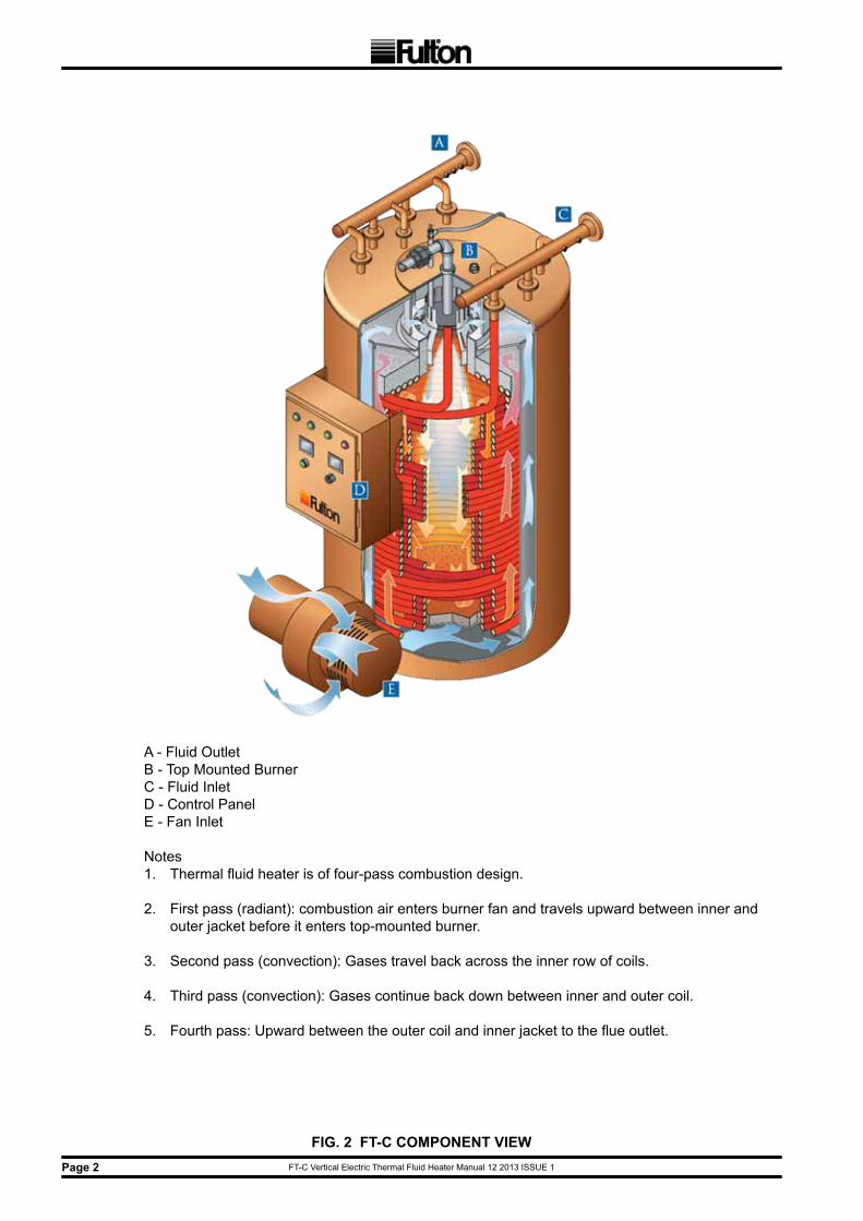
FIG. 2 FT-C COMPONENT VIEW
A - Fluid OutletB - Top Mounted BurnerC - Fluid InletD - Control PanelE - Fan Inlet
Notes1. Thermal fluid heater is of four-pass combustion design.
2. First pass (radiant): combustion air enters burner fan and travels upward between inner and outer jacket before it enters top-mounted burner.
3. Second pass (convection): Gases travel back across the inner row of coils.
4. Third pass (convection): Gases continue back down between inner and outer coil.
5. Fourth pass: Upward between the outer coil and inner jacket to the flue outlet.
FT-C Vertical Electric Thermal Fluid Heater Manual 12 2013 ISSUE 1 Page 3
2
SECTION 2 - INSTALLATION
The installation of a FT-C thermal fluid heater should be carried out by competent personnel in accordance with all relevant safety regulations. It is the responsibility of the installer to ensure that these regulations are complied with.
a) All components exposed to thermal fluid flow, including pipe, valves, and screens, must not be made out of copper, copper alloys, aluminium, or cast iron. Cast iron is porous to thermal fluids, and copper and aluminium act as catalysts in the degradation of some thermal fluids. Carbon or stainless steel, or ductile iron, are recommended.
b) For standard applications, all components must be rated to 350°C unless otherwise stipulated.
c) All pipework, valves, and user equipment must be suited to the maximum operating pressure of the heater. The maximum pressure stamped on the heater nameplate is typically 10.34 barg (150 psig).
d) If an isolating valve is completely closed, the pressure in the system will rise to the deadhead pressure of the pump. Suitably sized pipe will enable the system to withstand the total head generated by the circulating pump, should this occur. In applications where it is desirable to design to pressures lower than 6.9 barg (100 psig), an alternative safeguard is to install appropriately sized safety valves.
e) Where secondary circulating pumps are installed, the system must be suitable for the aggregate head, against a closed valve, of both pumps.
f) During construction of the installation, ensure that no dirt, water, or residue from welding is left in the system.
2.1 GENERAL
2.2 TRANSPORT
All Fulton Coil Design Heaters are shipped vertically and all units are crated for forklift transport. Once uncrated, all units with the exception of freestanding Models FT-0080-C, FT-0120-C, FT-0160-C, and FT-0240-C can be transported with a forklift.
These four models can only be lifted for unloading and moving by means of lifting lugs at the top of the heaters. If means of lifting are not available, rollers should be placed beneath the frame of the heater, and it should be guided to the position of where it is to be installed. Under no circumstancesshould weight be allowed to bear on the jacket, control panel, or fan housing of any Fulton Thermal Fluid Heater.
All stand alone heaters can be moved via a crane utilizing lifting lugs on top of the heater. The FT-0320-C and larger stand alone heaters can also be moved using a fork lift. All skidded units can be moved with forklifts.
FT-C Vertical Electric Thermal Fluid Heater Manual 12 2013 ISSUE 1Page 4
2
2.3 SITING
Reference should be made to Section 5.1 and 5.2 to ascertain the relevant dimensions and weights.
a) Authorities with jurisdiction over any national or local codes which might be applicable to thermal fluid applications should be consulted before installations are made.
b) The heater should be located as close as possible to the place where the heat will be used in order to keep pipe work costs to a minimum.
c) A level, hard, non-combustible surface is required for a suitable base for mounting the unit. It is suggested that a 100 mm curb be installed completely around the unit. In the event of a large spill, this will help contain the fluid.
d) Approximations for the floor loading of each heater can be calculated using the weights given in section 5.1. Check building specifications for permissible floor loading.
e) The heater should be placed in a suitable heater house or well ventilated separate room through which personnel do not normally pass. This is not essential, but the layout should eliminate traffic in potentially hazardous areas. For instance, the service engineer or the operator should not have to pass exposed, hot pipe work to make adjustments to the heater controls.
f) Ventilation must be sufficient to maintain a building temperature of 38°C or less and the panel box temperature must not exceed 52°C. Natural ventilation should be provided by means of grilles at floor and ceiling level.
g) To burn fuel properly, the burner must have an adequate supply of air. See Technical Information sheet for the heater for minimum make up air required and the recommended area of opening for each heater. If positive forced ventilation is adopted, you must ensure that there will be no appreciable pressure variation in the heater room.
FT-C Vertical Electric Thermal Fluid Heater Manual 12 2013 ISSUE 1 Page 5
2
2.4 GAS SUPPLY
Adhere to the following for gas supply installation:1) Install gas piping in accordance with all applicable codes.
2) Ensure pipe and fittings used are new and free of dirt or other deposits.
3) Ensure piping is of the proper size for adequate gas supply to the gas head assembly. Consult your gas company for specific recommendations.
4) When making gas piping joints, use a sealing compound resistant to the action of liquefied petroleum gases. Do not use Teflon tape on gas line heads.
5) Ensure no piping stresses are transmitted to the equipment. The equipment shall not be used as a pipe anchor.
6) Ensure all vent connections on diaphragms, gas valves, pressure regulators, and pressure switches (gas-fired units) are vented per local code.
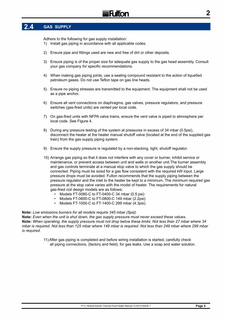
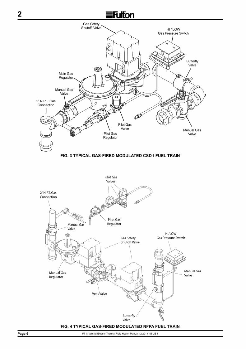
7) On gas-fired units with NFPA valve trains, ensure the vent valve is piped to atmosphere per local code. See Figure 4.
8) During any pressure testing of the system at pressures in excess of 34 mbar (0.5psi), disconnect the heater at the heater manual shutoff valve (located at the end of the supplied gas train) from the gas supply piping system.
9) Ensure the supply pressure is regulated by a non-stacking, tight, shutoff regulator.
10) Arrange gas piping so that it does not interfere with any cover or burner, inhibit service or maintenance, or prevent access between unit and walls or another unit.The burner assembly and gas controls terminate at a manual stop valve to which the gas supply should be connected. Piping must be sized for a gas flow consistent with the required kW input. Large pressure drops must be avoided. Fulton recommends that the supply piping between the pressure regulator and the inlet to the heater be kept to a minimum. The minimum required gas pressure at the stop valve varies with the model of heater. The requirements for natural gas-fired coil design models are as follows:
• Models FT-0080-C to FT-0400-C 34 mbar (0.5 psi)• Models FT-0600-C to FT-0800-C 149 mbar (2.2psi)• Models FT-1000-C to FT-1400-C 299 mbar (4.3psi)
Note: Low emissions burners for all models require 345 mbar (5psi).Note: Even when the unit is shut down, the gas supply pressure must never exceed these values.Note: When operating, the supply pressure must not drop below these limits: Not less than 27 mbar where 34 mbar is required. Not less than 125 mbar where 149 mbar is required. Not less than 249 mbar where 299 mbar is required.
11) After gas piping is completed and before wiring installation is started, carefully check all piping connections, (factory and field), for gas leaks. Use a soap and water solution.
FT-C Vertical Electric Thermal Fluid Heater Manual 12 2013 ISSUE 1Page 6
2Gas Safety
Shutoff Valve
Main GasRegulator
Manual GasValve
Pilot GasRegulator
Pilot GasValve Manual Gas
Valve
ButterflyValve
HI / LOWGas Pressure Switch
2” N.P.T. GasConnection
2” N.P.T. GasConnection
Manual GasRegulator
Manual GasValve
Vent Valve
Gas SafetyShutoff Valve
Manual Gas Valve
HI/LOWGas Pressure Switch
ButterflyValve
Pilot GasRegulator
Pilot GasValves
FIG. 3 TYPICAL GAS-FIRED MODULATED CSD-I FUEL TRAIN
FIG. 4 TYPICAL GAS-FIRED MODULATED NFPA FUEL TRAIN
FT-C Vertical Electric Thermal Fluid Heater Manual 12 2013 ISSUE 1 Page 7
2
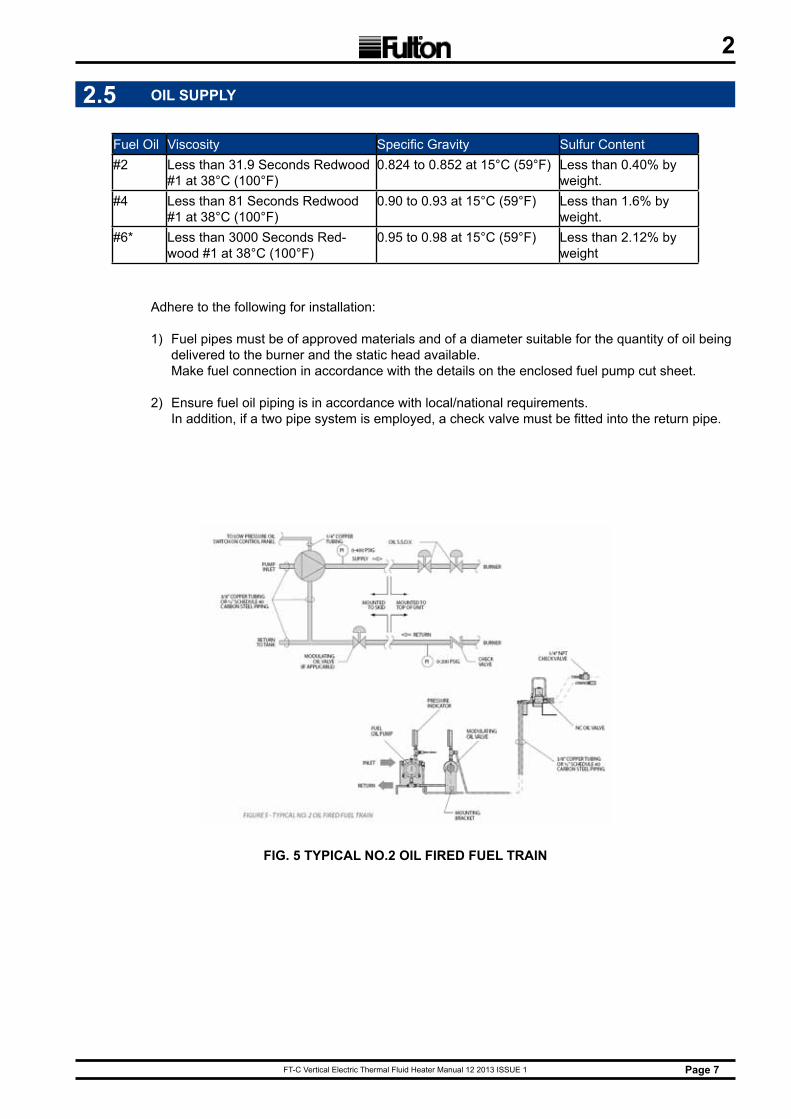
2.5 OIL SUPPLY
Adhere to the following for installation:
1) Fuel pipes must be of approved materials and of a diameter suitable for the quantity of oil being delivered to the burner and the static head available. Make fuel connection in accordance with the details on the enclosed fuel pump cut sheet.
2) Ensure fuel oil piping is in accordance with local/national requirements. In addition, if a two pipe system is employed, a check valve must be fitted into the return pipe.
Fuel Oil Viscosity Specific Gravity Sulfur Content#2 Less than 31.9 Seconds Redwood
#1 at 38°C (100°F)0.824 to 0.852 at 15°C (59°F) Less than 0.40% by
weight.#4 Less than 81 Seconds Redwood
#1 at 38°C (100°F)0.90 to 0.93 at 15°C (59°F) Less than 1.6% by
weight.#6* Less than 3000 Seconds Red-
wood #1 at 38°C (100°F)0.95 to 0.98 at 15°C (59°F) Less than 2.12% by
weight
FIG. 5 TYPICAL NO.2 OIL FIRED FUEL TRAIN
FT-C Vertical Electric Thermal Fluid Heater Manual 12 2013 ISSUE 1Page 8
2
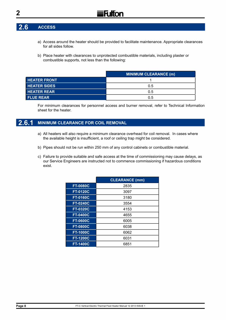
2.6.1 MINIMUM CLEARANCE FOR COIL REMOVAL
a) All heaters will also require a minimum clearance overhead for coil removal. In cases where the available height is insufficient, a roof or ceiling trap might be considered.
b) Pipes should not be run within 250 mm of any control cabinets or combustible material.
c) Failure to provide suitable and safe access at the time of commissioning may cause delays, as our Service Engineers are instructed not to commence commissioning if hazardous conditions exist.
2.6 ACCESS
a) Access around the heater should be provided to facilitate maintenance. Appropriate clearances for all sides follow.
b) Place heater with clearances to unprotected combustible materials, including plaster or combustible supports, not less than the following:
MINIMUM CLEARANCE (m)HEATER FRONT 1HEATER SIDES 0.5HEATER REAR 0.5FLUE REAR 0.5
CLEARANCE (mm)FT-0080C 2835FT-0120C 3097FT-0160C 3180FT-0240C 3554FT-0320C 4153FT-0400C 4655FT-0600C 6005FT-0800C 6038FT-1000C 6062FT-1200C 6031FT-1400C 6851
For minimum clearances for personnel access and burner removal, refer to Technical Information sheet for the heater.
FT-C Vertical Electric Thermal Fluid Heater Manual 12 2013 ISSUE 1 Page 9
2
2.7 SYSTEM CONNECTIONS
If screwed connections have to be made, e.g. to items of control equipment, then a thread sealant suitable for use with fluids at elevated temperature must be used. Teflon tape, standard pipe dope, or hemp and paste are not acceptable. Screw threads must be carefully and accurately cut. If possible, new tools should be used. Threaded connections larger than DN25 are not to be used. It is recommended that class 8.8 or better tensile steel bolts be used for all flanged joints.
2.7.2 HEATER CONNECTIONS
a) The outlet of the pump should connect directly to the inlet of the heater via an isolating valve and pump flexible connector.
b) The heater outlet should be piped directly to the system, via an isolating valve.
c) A safety relief valve may be shipped in the parts box accompanying the electric heater, and must be installed in the outlet manifold. On all units, the outlet of the safety relief valve must be piped to a catch tank. The discharge flow must not be restricted, i.e. no valve should be installed, there should be no reduction in pipe size, and the minimum number of bends possible. The weight of the piping must be properly supported in order to prevent damage to the safety valve. If the valve body becomes warped, leakage may result.
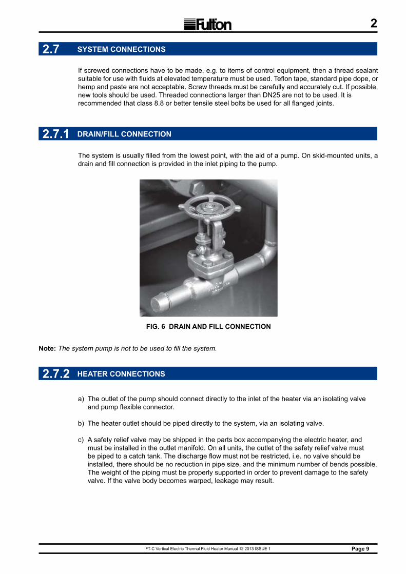
The system is usually filled from the lowest point, with the aid of a pump. On skid-mounted units, a drain and fill connection is provided in the inlet piping to the pump.
FIG. 6 DRAIN AND FILL CONNECTION
2.7.1 DRAIN/FILL CONNECTION
Note: The system pump is not to be used to fill the system.
FT-C Vertical Electric Thermal Fluid Heater Manual 12 2013 ISSUE 1Page 10
2
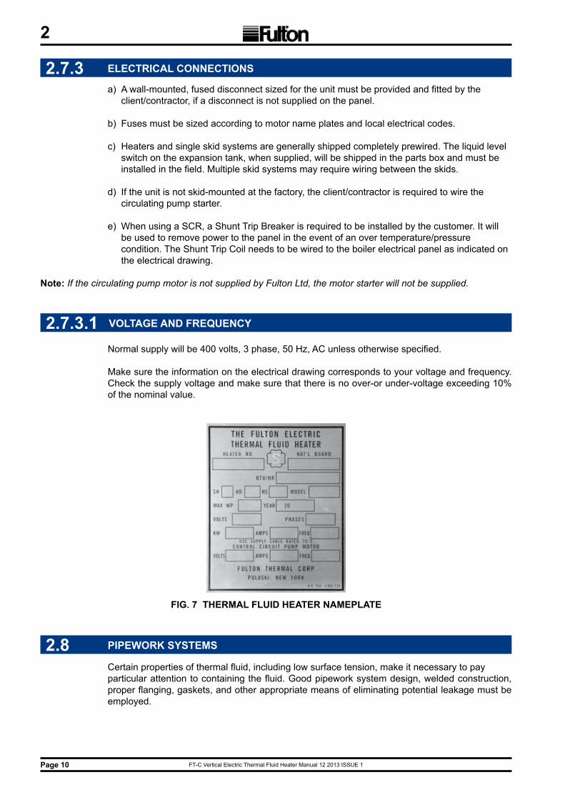
2.7.3.1 VOLTAGE AND FREQUENCY
Normal supply will be 400 volts, 3 phase, 50 Hz, AC unless otherwise specified.
Make sure the information on the electrical drawing corresponds to your voltage and frequency. Check the supply voltage and make sure that there is no over-or under-voltage exceeding 10% of the nominal value.
2.7.3 ELECTRICAL CONNECTIONS
a) A wall-mounted, fused disconnect sized for the unit must be provided and fitted by the client/contractor, if a disconnect is not supplied on the panel.
b) Fuses must be sized according to motor name plates and local electrical codes.
c) Heaters and single skid systems are generally shipped completely prewired. The liquid level switch on the expansion tank, when supplied, will be shipped in the parts box and must be installed in the field. Multiple skid systems may require wiring between the skids.
d) If the unit is not skid-mounted at the factory, the client/contractor is required to wire the circulating pump starter.
e) When using a SCR, a Shunt Trip Breaker is required to be installed by the customer. It will be used to remove power to the panel in the event of an over temperature/pressure condition. The Shunt Trip Coil needs to be wired to the boiler electrical panel as indicated on the electrical drawing.
Note: If the circulating pump motor is not supplied by Fulton Ltd, the motor starter will not be supplied.
FIG. 7 THERMAL FLUID HEATER NAMEPLATE
2.8 PIPEWORK SYSTEMS
Certain properties of thermal fluid, including low surface tension, make it necessary to pay particular attention to containing the fluid. Good pipework system design, welded construction, proper flanging, gaskets, and other appropriate means of eliminating potential leakage must be employed.
FT-C Vertical Electric Thermal Fluid Heater Manual 12 2013 ISSUE 1 Page 11
2
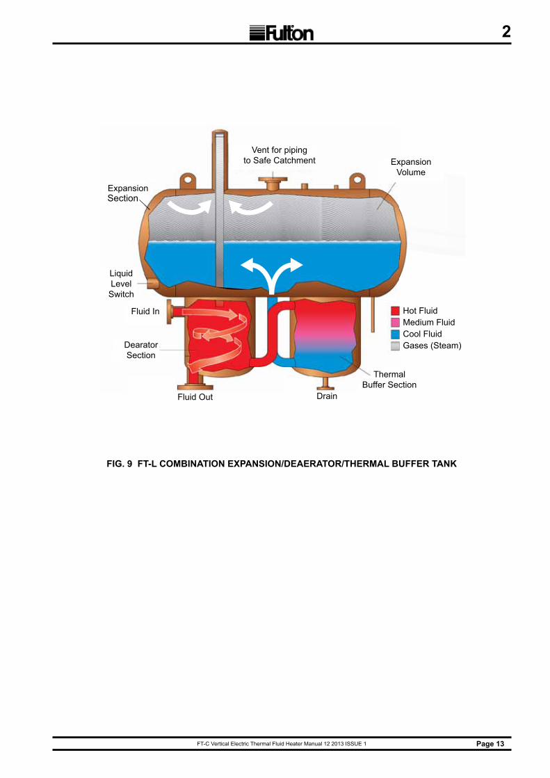
2.9 COMBINATION EXPANSION/DEAERATOR/THERMAL BUFFER TANK
Fulton Ltd's efficient design combines the operation of the expansion, deaerator, and thermal buffer tanks. Installation is considerably simplified by virtue of this arrangement.
The tank will be constructed of carbon steel. It shall be supplied with expansion section liquid level switch and PN16 flanged connections.
The tank may be built to BS EN 13445: 2009 upon request. Non-coded tanks should not be pressurised above 0.5 barg.
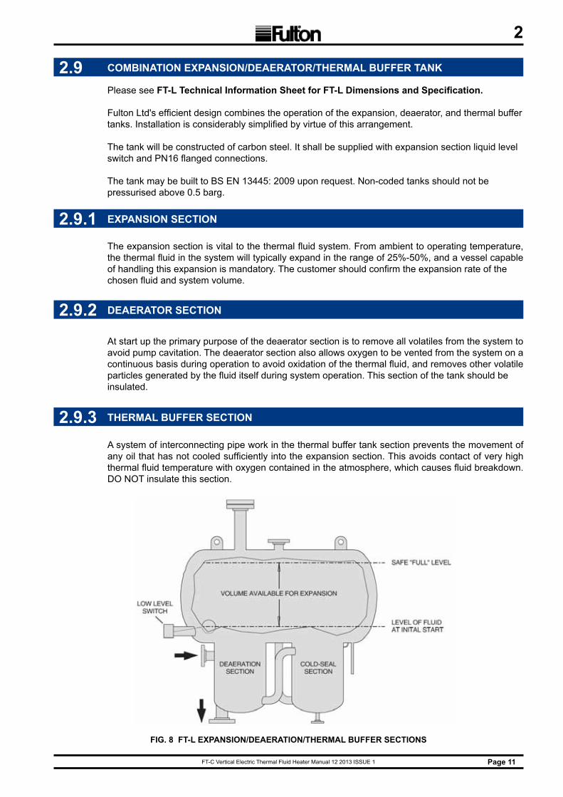
2.9.1 EXPANSION SECTION
The expansion section is vital to the thermal fluid system. From ambient to operating temperature, the thermal fluid in the system will typically expand in the range of 25%-50%, and a vessel capable of handling this expansion is mandatory. The customer should confirm the expansion rate of the chosen fluid and system volume.
2.9.2 DEAERATOR SECTION
At start up the primary purpose of the deaerator section is to remove all volatiles from the system to avoid pump cavitation. The deaerator section also allows oxygen to be vented from the system on a continuous basis during operation to avoid oxidation of the thermal fluid, and removes other volatile particles generated by the fluid itself during system operation. This section of the tank should be insulated.
FIG. 8 FT-L EXPANSION/DEAERATION/THERMAL BUFFER SECTIONS
2.9.3 THERMAL BUFFER SECTION
A system of interconnecting pipe work in the thermal buffer tank section prevents the movement of any oil that has not cooled sufficiently into the expansion section. This avoids contact of very high thermal fluid temperature with oxygen contained in the atmosphere, which causes fluid breakdown. DO NOT insulate this section.
Please see FT-L Technical Information Sheet for FT-L Dimensions and Specification.
FT-C Vertical Electric Thermal Fluid Heater Manual 12 2013 ISSUE 1Page 12
2
2.9.4 SIzING THE TANK FOR THE SYSTEM
Combination tank capacity is the total volume of the tank. It is necessary to have some air space available at the top of the tank to avoid spillage or overflow. At initial fill (for system volume calculations) the deaerator and thermal buffer sections must be filled completely and the expansion section must be filled to a level of 100 mm to "make" the liquid level switch.
The volume between the initial fill level and the safe "full" level is the amount available for expansion. That volume is used to decide which tank is suitable for the system expansion.
Sizing Example
A system contains 660 litres, including the heater, but not the tank. You select the FT-200-L, so you add 95 litres to 660. You must look up the expansion rate for the thermal fluid. (Assume it is 25%). 755 litres x 1.25 = 945 litres. 945-755 = 190 litres expansion. The FT-200-L has only 75 litres available for expansion, so the correct selection is the FT-500-L.
2.9.5 LOCATION
a) The combination tank must be installed in accordance with Fulton Ltd's specifications.
b) Unless the system is pressurised, the inlet to the deaerator section must be higher than or equal to the highest point in the system to prevent pockets of air from collecting in system piping.
c) The head required at the circulation pump suction inlet must also be taken into account to avoid the possibility of pump cavitation. In systems operating close to maximum fluid temperature, the tank must be elevated enough, possibly well above the highest point in the system to prevent pump cavitation by increasing the static head. An inert pressurising blanket may be considered as an alternative. See Pressurised Systems, sections 2.9.6
d) Supports for tank mounting should be provided by the client/contractor. These should be suited for supporting the tank by the side rails. The eyelets fitted to the tank are for lifting only.
FT-C Vertical Electric Thermal Fluid Heater Manual 12 2013 ISSUE 1 Page 13
2
ExpansionVolume
Vent for piping to Safe Catchment
ExpansionTank
Hot FluidMedium FluidCool FluidGases (Steam)
ThermalBuffer Section
DrainFluid Out
Liquid Level Switch
Fluid In
DearatorSection
FIG. 9 FT-L COMBINATION EXPANSION/DEAERATOR/THERMAL BUFFER TANK
Section
FT-C Vertical Electric Thermal Fluid Heater Manual 12 2013 ISSUE 1Page 14
2
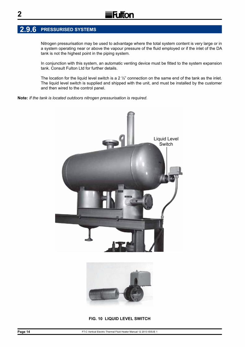
2.9.6 PRESSURISED SYSTEMS
Nitrogen pressurisation may be used to advantage where the total system content is very large or in a system operating near or above the vapour pressure of the fluid employed or if the inlet of the DA tank is not the highest point in the piping system.
In conjunction with this system, an automatic venting device must be fitted to the system expansion tank. Consult Fulton Ltd for further details.
The location for the liquid level switch is a 2 ½” connection on the same end of the tank as the inlet. The liquid level switch is supplied and shipped with the unit, and must be installed by the customer and then wired to the control panel.
Note: If the tank is located outdoors nitrogen pressurisation is required.
Liquid Level Switch
FIG. 10 LIQUID LEVEL SWITCH
FT-C Vertical Electric Thermal Fluid Heater Manual 12 2013 ISSUE 1 Page 15
2
2.9.7 CONNECTIONS
a) The vent connection must be made in a manner that will prevent penetration of water or foreign bodies into the tank. This connection must always terminate in a safe, well ventilated area and has to be free of obstruction, open to atmosphere, and arranged in such a manner that, in the event of discharge from the system, thermal fluid could drain into a catch tank without danger to personnel or property.
Note: Non-code tanks cannot be pressurised over 0.5 barg.
b) The vent run should be the same size as the tank outlet. It should run pitch down from the outlet of the tank to the catch tank.
c) If nitrogen is used on the system, the vent can be reduced to DN50 and should be piped with a positive closing valve at the catch tank.
d) The connection between the tank outlet and the horizontal pump inlet run should be as close to a vertical drop as possible. It should not contain an excessive number of bends of length of pipe. These faults could encourage pump cavitation.
e) As noted, the inlet to the combination tank must be higher than or equal to the highest point in the system or a pressurised system must be used.
f) The liquid level switch, supplied and shipped with the unit, must be installed and wired to the control panel by the customer.
g) The high and low level test connections are DN15, and are located on the end of the tank opposite the inlet. The low level is on the centre line of the tank, the high level is next to it, slightly off centre. The high level rises up from the bottom of the tank and ends 100 mm below the top; the low level rises 50 mm from the bottom of the tank.
h) Both the high and low level connections should be piped to a safe catchment. Valves should be installed in these lines at the catch tank. Installation of the valves should be accomplished in such a manner that any flow will be visible when the valves are open. Flow from the high level test connection indicates a tank that is too full; no flow from the low level test connection indicates too little fluid.
i) There is a PN16 flanged drain on the bottom of the thermal buffer section, for the purpose of draining the tank when necessary. This should be piped with a valve in the line, to a safe catchment. The valve specifications outlined above apply to this valve as well.
j) An inspection opening is located at the highest point on the tank. Access to this port is recommended but not required.
k) Refer to the maintenance schedule for recommendations on draining the thermal buffer section. For positioning of all connections on tank, see Fig 8. FT-L Combination Expansion/Deaerator/Thermal Buffer Tank.
WARNINGHigh temperature thermal fluid, steam and combustible vapours may be vented
through this connection.
!
WARNINGOnce the system has been filled, any modification to the tank or connected piping requires
purging of the work area to prevent ignition of potentially flammable vapours. Consult factory prior to beginning work. Consult the MSDS for your thermal fluid for flammability limits.
!
FT-C Vertical Electric Thermal Fluid Heater Manual 12 2013 ISSUE 1Page 16
2
FIG. 3 CIRCULATING PUMP
The pump should be located adjacent to the heater. Its base must be firm, level (preferably concrete), and free from vibration.
2.10.1 LOCATION
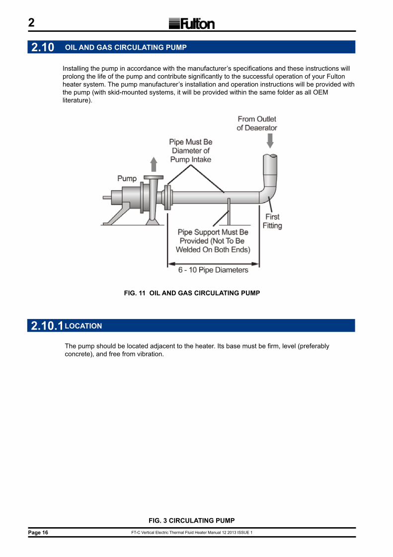
2.10 OIL AND GAS CIRCULATING PUMP
Installing the pump in accordance with the manufacturer’s specifications and these instructions will prolong the life of the pump and contribute significantly to the successful operation of your Fulton heater system. The pump manufacturer’s installation and operation instructions will be provided with the pump (with skid-mounted systems, it will be provided within the same folder as all OEM literature).
FIG. 3 CIRCULATING PUMP
FIG. 11 OIL AND GAS CIRCULATING PUMP
FT-C Vertical Electric Thermal Fluid Heater Manual 12 2013 ISSUE 1 Page 17
2
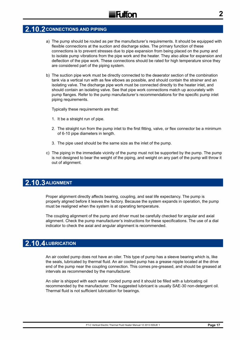
2.10.2 CONNECTIONS AND PIPIING
a) The pump should be routed as per the manufacturer’s requirements. It should be equipped with flexible connections at the suction and discharge sides. The primary function of these connections is to prevent stresses due to pipe expansion from being placed on the pump and to isolate pump vibrations from the pipe work and the heater. They also allow for expansion and deflection of the pipe work. These connections should be rated for high temperature since they are considered part of the piping system.
b) The suction pipe work must be directly connected to the deaerator section of the combination tank via a vertical run with as few elbows as possible, and should contain the strainer and an isolating valve. The discharge pipe work must be connected directly to the heater inlet, and should contain an isolating valve. See that pipe work connections match up accurately with pump flanges. Refer to the pump manufacturer’s recommendations for the specific pump inlet piping requirements. Typically these requirements are that:
1. It be a straight run of pipe.
2. The straight run from the pump inlet to the first fitting, valve, or flex connector be a minimum of 6-10 pipe diameters in length.
3. The pipe used should be the same size as the inlet of the pump.
c) The piping in the immediate vicinity of the pump must not be supported by the pump. The pump is not designed to bear the weight of the piping, and weight on any part of the pump will throw it out of alignment.
2.10.3 ALIGNMENT
Proper alignment directly affects bearing, coupling, and seal life expectancy. The pump is properly aligned before it leaves the factory. Because the system expands in operation, the pump must be realigned when the system is at operating temperature.
The coupling alignment of the pump and driver must be carefully checked for angular and axial alignment. Check the pump manufacturer’s instructions for these specifications. The use of a dial indicator to check the axial and angular alignment is recommended.
2.10.4 LUBRICATION
An air cooled pump does not have an oiler. This type of pump has a sleeve bearing which is, like the seals, lubricated by thermal fluid. An air cooled pump has a grease nipple located at the drive end of the pump near the coupling connection. This comes pre-greased, and should be greased at intervals as recommended by the manufacturer.
An oiler is shipped with each water cooled pump and it should be filled with a lubricating oil recommended by the manufacturer. The suggested lubricant is usually SAE-30 non-detergent oil. Thermal fluid is not sufficient lubrication for bearings.
FT-C Vertical Electric Thermal Fluid Heater Manual 12 2013 ISSUE 1Page 18
2
2.10.6 AIR COOLING
a) Allow for free air flow around the entire pump casing at all times.
b) Maximum room temperature should be 38°C.
c) In no case should any part of the drive side of the pump be insulated.
d) Maximum operating temperature for air cooled pumps varies by manufacturer. Consult instruction manual to verify.
2.10.7 WATER COOLING
a) A throttling needle valve should be installed on the inlet side of the water cooling passages and adjusted so that the outlet water is between 49°C. and 71°C. Typically this means a flow rate of 0.1 l/s - 0.3 l/s at 4°C inlet temperature. Consult pump manufacturer’s specifications for dimensions of water cooling connection.
b) The throttling valve on a water cooled pump is designed to automatically give the proper flow rate for a 2.75 barg or greater supply.
c) If a minimum of 2.75 barg is not available, consult Fulton Ltd. about re-sizing the orifice. If the temperature of the cooling water is greater than 13 °C to begin with, a correspondingly greater flow rate is required.
d) For automatic operation of water cooling, wire a solenoid valve on the inlet to open whenever the pump motor starter is energised.
e) The outlet flow from the pump must not be restricted in any manner. Therefore, valves are not to be installed on the outlet. Check local codes regarding disposal of hot water.
2.10.5 SEALS
All seals on air cooled pumps are lubricated by thermal fluid, therefore the pump must never be run dry, i.e. without thermal fluid in it.
Filling a pump equipped with either a Grafoil packed or mechanical seal with thermal fluid will ensure lubrication. However, in order to be certain that all seals on an air cooled pump are coated with thermal fluid, the pump must be bled.
Grafoil packings require a run-in procedure. Typically, pumps with these seals are shipped with four or five rings installed and several rings loose. These extra rings must be on hand for the initial run-in procedure. See manufacturer’s instruction manual for this procedure.
FT-C Vertical Electric Thermal Fluid Heater Manual 12 2013 ISSUE 1 Page 19
2
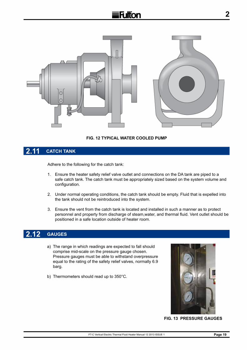
FIG. 12 TYPICAL WATER COOLED PUMP
Adhere to the following for the catch tank:
1. Ensure the heater safety relief valve outlet and connections on the DA tank are piped to a safe catch tank. The catch tank must be appropriately sized based on the system volume and configuration.
2. Under normal operating conditions, the catch tank should be empty. Fluid that is expelled into the tank should not be reintroduced into the system.
3. Ensure the vent from the catch tank is located and installed in such a manner as to protect personnel and property from discharge of steam,water, and thermal fluid. Vent outlet should be positioned in a safe location outside of heater room.
2.11 CATCH TANK
2.12 GAUGES
a) The range in which readings are expected to fall should comprise mid-scale on the pressure gauge chosen. Pressure gauges must be able to withstand overpressure equal to the rating of the safety relief valves, normally 6.9 barg.
b) Thermometers should read up to 350°C.
FIG. 13 PRESSURE GAUGES

FT-C Vertical Electric Thermal Fluid Heater Manual 12 2013 ISSUE 1Page 20
2
2.13 VALVES
a) Vent and drain valves should normally be DN15 or DN20 with internal seals made from materials suited to use with thermal fluids. They may be of the screw type if installed on stalks not less than 300 mm long.
b) Gasketing material specifically suited to the task must be used.
c) Drain valves should be fitted at all low points in the pipework system and ventilating valves should be fitted at all high points in the installation.
d) Valves must be fitted with either the conventional packed stuffing box seal or a bellows seal as required. Where the stuffing box is specified, it should be as deep as possible and packed with Grafoil packing or equal. The valves should have a back seating to allow re-packing without draining the system.
e) In all units, a “Y” type strainer should be installed in the fluid return line, between the combination tank and the circulating pump. Valves must be provided (unless the heater has been skid-mounted with the tank) so that the strainer can be isolated for cleaning of the element. The strainer element should be 60 mesh and must remain in place during normal operation of the system.
2.14 PIPING
a) All pipework should be constructed from seamless mild steel pipe, conforming to BS EN 10216:2002 or ASTM A106:B, Schedule 40 or equal.
b) Ensure all components exposed to thermal fluid flow, including pipe, valves, and screens, are not copper, copper alloys, bronze, brass, aluminum, or cast iron. Cast iron is porous to thermal fluids, and copper and aluminum act as catalysts in the degradation of some thermal fluids. Carbon or stainless steel, or ductile iron, are recommended.
c) Expansion joints or properly designed and sited loops should be provided to accommodate thermal expansion. Thermal expansion should be calculated using the maximum possible utilisation fluid temperature, regardless of whether the pipe considered is in the feed or return circuit. Steel pipe will expand approximately 1 mm. per meter over a 100°C temperature rise.
d) Supports and anchors must be provided for all pipes where necessary to prevent undue stresses from being placed on items of equipment, including pumps, valves, and the heater. Supports and anchors which will not interfere with thermal expansion should be chosen.
e) All pipe joints should be of either welded or flanged construction. Screwed joints must be avoided where possible. In no instance should screwed joints be used in the flow circuit.
f) All flanges should be welded to the pipe and not screwed. Flanges should be PN16 or PN25 raised face flanges, BS4504.
g) If screwed connections have to be made, e.g., to items of control equipment, use a thread sealant suitable for use with fluids at elevated temperature. Teflon tape, standard pipe sealant, or hemp and paste are not acceptable.
h) Cut screw threads carefully and accurately. If possible, new tools should be used. Threaded connections larger than 1” are not to be used. It is recommended that GR5 or higher tensile steel bolts be used for all flanged joints.
i) Gasketing material suitable for use with thermal fluids at high temperatures should be used to make all flanged joints. Flexible graphite gaskets are suited for most thermal fluids. Recommended gasket thickness is 2.5 - 3 mm.
FT-C Vertical Electric Thermal Fluid Heater Manual 12 2013 ISSUE 1 Page 21
2
20
23
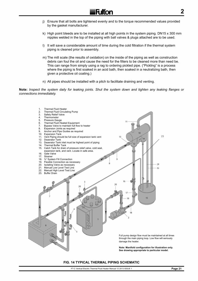
1. Thermal Fluid Heater 2. Thermal Fluid Circulating Pump 3. Safety Relief Valve 4. Thermometer 5. Pressure Gauge 6. Thermal Fluid Heated Equipment 7. Bypass Valve to maintain full flow to heater 8. Expansion Joints as required 9. Anchor and Pipe Guides as required 10. Expansion Tank 11. Vent Piping should be full size of expansion tank vent 12. Deaerator Tank 13. Deaerator Tank inlet must be highest point of piping 14. Thermal Buffer Tank 15. Catch Tank for drain of pressure relief valve, cold seal,
expansion tank, and vent. Locate in safe area. 16. Gate Valve 17. Strainer 18. ¾” System Fill Connection 19. Flexible Connection as necessary 20. Isolating Valve as necessary 21. Manual Low Level Test Line 22. Manual High Level Test Line 23. Buffer Drain
Full pump design flow must be maintained at all times thru the main piping loop. Low flow will seriously damage heater.
Note: Manifold configuration for illustration only. See drawing appropriate to particular model.
FIG. 14 TYPICAL THERMAL PIPING SCHEMATIC
j) Ensure that all bolts are tightened evenly and to the torque recommended values provided by the gasket manufacturer.
k) High point bleeds are to be installed at all high points in the system piping. DN15 x 300 mm nipples welded in the top of the piping with ball valves & plugs attached are to be used.
l) It will save a considerable amount of time during the cold filtration if the thermal system piping is cleaned prior to assembly.
m) The mill scale (the results of oxidation) on the inside of the piping as well as construction debris can foul the oil and cause the need for the filters to be cleaned more than need be. This can range from simply using a rag to ordering pickled pipe. (“Pickling” is a process where the piping is first soaked in an acid bath, then soaked in a neutralizing bath, then given a protective oil coating.)
n) All pipes should be installed with a pitch to facilitate draining and venting.
Note: Inspect the system daily for leaking joints. Shut the system down and tighten any leaking flanges or connections immediately.
Full pump design flow must be maintained at all times through the main piping loop. Low flow will seriously damage the heater.
Note: Manifold configuration for illustration only. See drawing appropriate to particular model.
FT-C Vertical Electric Thermal Fluid Heater Manual 12 2013 ISSUE 1Page 22
2
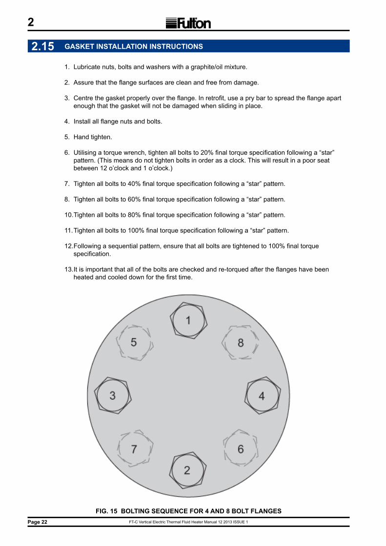
FIG. 15 BOLTING SEQUENCE FOR 4 AND 8 BOLT FLANGES
2.15 GASKET INSTALLATION INSTRUCTIONS
1. Lubricate nuts, bolts and washers with a graphite/oil mixture.
2. Assure that the flange surfaces are clean and free from damage.
3. Centre the gasket properly over the flange. In retrofit, use a pry bar to spread the flange apart enough that the gasket will not be damaged when sliding in place.
4. Install all flange nuts and bolts.
5. Hand tighten.
6. Utilising a torque wrench, tighten all bolts to 20% final torque specification following a “star” pattern. (This means do not tighten bolts in order as a clock. This will result in a poor seat between 12 o’clock and 1 o’clock.)
7. Tighten all bolts to 40% final torque specification following a “star” pattern.
8. Tighten all bolts to 60% final torque specification following a “star” pattern.
10. Tighten all bolts to 80% final torque specification following a “star” pattern.
11. Tighten all bolts to 100% final torque specification following a “star” pattern.
12. Following a sequential pattern, ensure that all bolts are tightened to 100% final torque specification.
13. It is important that all of the bolts are checked and re-torqued after the flanges have been heated and cooled down for the first time.
FT-C Vertical Electric Thermal Fluid Heater Manual 12 2013 ISSUE 1 Page 23
2
RECOMMENDED LOADS FOR JM CLIPPER ELASTOGRAPH 300# GASKETS SAE GRADE 5 BOLTS (TYPICAL) OR EQUAL
NOMINAL FLANGE SIzE (INCHES) NUMBER OF BOLTS DIAMETER OF BOLTS
(INCHES)
PREFERRED TORQUE REQUIRED PER BOLT
(FT-LBS)1/2 4 1/2 413/4 4 5/8 811 4 5/8 81
1 1/4 4 5/8 811 1/2 4 3/4 136
2 8 5/8 812 1/2 8 3/4 136
3 8 3/4 1364 8 3/4 1365 8 3/4 1366 12 3/4 2178 12 7/8 33210 16 1 217
RECOMMENDED LOADS FOR JM CLIPPER ELASTOGRAPH 150# GASKETS SAE GRADE 5 BOLTS (TYPICAL) OR EQUAL
NOMINAL FLANGE SIzE (INCHES) NUMBER OF BOLTS DIAMETER OF BOLTS
(INCHES)
PREFERRED TORQUE REQUIRED PER BOLT
(FT-LBS)1/2 4 1/2 413/4 4 1/2 411 4 1/2 41
1 1/4 4 1/2 411 1/2 4 1/2 41
2 4 5/8 812 1/2 4 5/8 81
3 4 5/8 814 8 5/8 815 8 3/4 1366 8 3/4 1368 8 3/4 13610 12 7/8 217
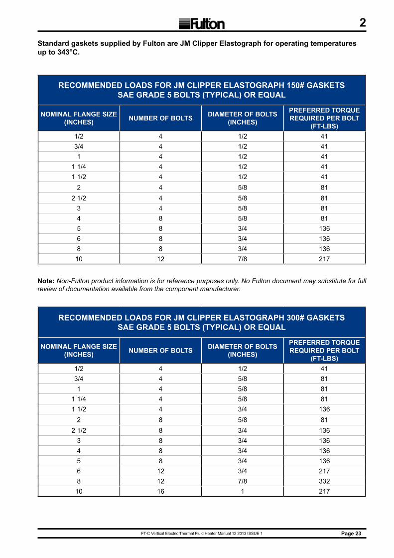
Standard gaskets supplied by Fulton are JM Clipper Elastograph for operating temperatures up to 343°C.
Note: Non-Fulton product information is for reference purposes only. No Fulton document may substitute for full review of documentation available from the component manufacturer.
FT-C Vertical Electric Thermal Fluid Heater Manual 12 2013 ISSUE 1Page 24
2
RECOMMENDED LOADS FOR FLEXITALLIC SPIRAL WOUND 150# GASKETS SAE GRADE 5 BOLTS (TYPICAL) OR EQUAL
NOMINAL FLANGE SIzE (INCHES) NUMBER OF BOLTS DIAMETER OF BOLTS
(INCHES)
PREFERRED TORQUE REQUIRED PER BOLT
(Nm)1/2 4 1/2 613/4 4 1/2 611 4 1/2 61
1 1/4 4 1/2 611 1/2 4 1/2 61
2 4 5/8 1222 1/2 4 5/8 122
3 4 5/8 1223 1/2 8 5/8 122
4 8 5/8 1225 8 3/4 2036 8 3/4 2038 8 3/4 20310 12 7/8 325
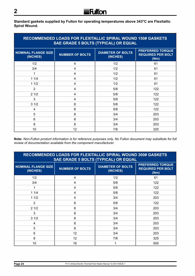
Standard gaskets supplied by Fulton for operating temperatures above 343°C are Flexitallic Spiral Wound.
RECOMMENDED LOADS FOR FLEXITALLIC SPIRAL WOUND 300# GASKETS SAE GRADE 5 BOLTS (TYPICAL) OR EQUAL
NOMINAL FLANGE SIzE (INCHES) NUMBER OF BOLTS DIAMETER OF BOLTS
(INCHES)
PREFERRED TORQUE REQUIRED PER BOLT
(Nm)1/2 4 1/2 613/4 4 5/8 1221 4 5/8 122
1 1/4 4 5/8 1221 1/2 4 3/4 203
2 8 5/8 1222 1/2 8 3/4 203
3 8 3/4 2033 1/2 8 3/4 203
4 8 3/4 2035 8 3/4 2036 12 3/4 2038 12 7/8 32510 16 1 500
Note: Non-Fulton product information is for reference purposes only. No Fulton document may substitute for full review of documentation available from the component manufacturer.

FT-C Vertical Electric Thermal Fluid Heater Manual 12 2013 ISSUE 1 Page 25
2
f) The pump suction pressure should be checked periodically, under similar operating conditions. A vacuum reading on the suction gauge indicates that the screen must be cleaned. For isolating purposes, globe, wedge, gate, ball, or other shut-off valves should be used. When there is a likelihood that some manual balancing will be required, a ball or globe valve should be used.
g) Manual control and isolating valves should be the flanged or weld type, manufactured from cast or forged steel or ductile iron, with internals and gland seals made from materials suitable for use with high temperature fluids.
h) When ordering valves, the maximum possible service temperature and type of fluid must be indicated on the order.
j) A partial list of manufacturers known to market valves of acceptable quality follows:
1. Ari Arimaturen2. Velan3. Vogt Machine Company4. Worcester Valve Company
k) Automatic Fluid Control Valves
1. Because of the widely varied processes Fulton Thermal Fluid Heaters are used in, it is not possible to set down specific rules for the selection of automatic fluid control valves. Generally, these valves must satisfy the materials and construction requirements described above.
2. The type of operation and design of porting are governed by the degree of control required as well as the particular application.
l) Bypass Valves
1. When process flow requirements do not match heater flow requirements, a by-pass valve must be installed.
2. If the process flow will vary with the system load, a suitable bypass system can be recommended by Fulton Ltd.
2.16 TESTING
a) Upon completion of the installation, a pneumatic test not exceeding 0.5 barg should be conducted. Soap tests should be made at all welds and joints to ensure that the system is free from leaks.
b) Under no circumstances should the system be filled with water. Make sure that the air supply is as free from moisture as possible.
c) The most satisfactory method of testing is to introduce bottled nitrogen through a pressure control valve. Check pressure ratings on all the equipment in the system to make sure that it is capable of withstanding the pressure involved.
d) The time needed to be spent during boilout directly corresponds to the amount of moisture in the system. Boilout can take anywhere from two to three days to complete. Pressure testing on the system should be done by means of an inert gas, such as nitrogen, or by an air compressor producing dry air (air with a dew point of 10°C or less). Never perform a hydrostatic test on the system.
FT-C Vertical Electric Thermal Fluid Heater Manual 12 2013 ISSUE 1Page 26
2
2.17 INSULATION
a) After the appropriate system tests have been satisfactorily completed, all hot pipework, including manifolds on the heater, must be adequately insulated with material suited to the temperature and application to prevent both heat loss and personnel injury.
b) The deaerator section of the combination tank must be insulated. The expansion section of the combination tank must not be insulated, nor should the thermal buffer section.
c) On units operated with inert gas blankets above the fluid in the expansion tank, the entire combination tank, including the expansion and thermal buffer sections, may be insulated, but is not necessary.
d) It is recommended that for inspection and maintenance, pumps, flanges, valves, and fittings be left un-insulated but suitably shielded for safety.
e) Hot oil pipe insulation should be a minimum of 50 mm thick, high temperature, laminated, foamglass cellular glass insulation as manufactured by Pittsburgh Corning Corporation, or equal.
2.18 THERMAL FLUIDS
2.18.1 THERMAL FLUIDS AT ELEVATED TEMPERATURES
a) Plant engineers must be familiar with the nature of potential hazards when working with thermal fluids at operating temperatures.
b) Unlike steam or high-pressure water systems, thermal fluid attains extremely high temperatures without a corresponding increase in pressure. While this lack of high pressure in the system yields many advantages, a false sense of security should not be allowed to develop on account of this alone.
c) Certain types of thermal fluid may have operating temperatures reaching 345°C and above, so all exposed pipework is hazardous and should be insulated, as indicated in the preceding sections.
d) Flanged joints must be checked for tightness during and after the first warming up of the system. After these checks, exposed hot flanges, pumps, valves and fittings should be fitted with some sort of shield.
e) It is important to remember that there is pressure generated in the system by the circulating pump. Great care should be exercised when opening any drain or vent valves in the system.This is especially important during commissioning, when any air trapped in the system is vented at high points, and when water, which will flash into steam, is either expelled from the combination tank vent or drained off at low points.
f) If a fire does occur, extinguish using CO2, foam or dry chemical. DO NOT USE WATER.
CAUTIONDuring operation, any leaks are usually detected by a small amount
of vapour. Leaks should be attended to as soon as possible because under certain circumstances, such as saturated insulation, thermal fluid
can ignite when exposed to air and heat.
!
FT-C Vertical Electric Thermal Fluid Heater Manual 12 2013 ISSUE 1 Page 27
2
a) The selection of the thermal fluid most suited to your application is very important. Factors to be considered include efficiency, thermal stability, and adaptability to various systems, and physical properties, including vapour pressure, freezing point, and flash and fire points.
b) Heat transfer fluids of both mineral and synthetic origin have been specially developed to give thermal stability over a very wide range of temperature. A wide variety of thermal fluids have been used successfully in Fulton Thermal Fluid Heater systems, however, your final selection should be made in conjunction with Fulton Ltd. or the fluid manufacturer.
c) The safe control and monitoring of the thermal fluid temperature is of paramount importance.
d) The safe maximum bulk temperature of the fluid must be strictly adhered to. The safe maximum temperature of the fluid varies, but a typical maximum for many types of mineral oil based fluids is 320°C.
e) Special care must be taken when consulting fluid manufacturers’ literature, as maximum fluid temperatures quoted are the actual limit to which any of the fluids may be subjected. It is important to remember that in any fired heater there exists a “film temperature” which is higher than the temperature of the “bulk” of the fluid.
f) It is the BULK fluid temperature and NOT the FILM temperature that is indicated by the instruments.
g) As a general guide, the following list of fluids that have given satisfactory service over many years is provided.
h) This is by no means a complete list. Any fluid specifically designed for heat transfer use may be considered; multipurpose oils are not acceptable.
1. AMOCO Transfer Oil 4199
2. CHEVRON Teknifax
3. DOW Dowtherm A or G
4. EXXON Caloria HT 43
5. MOBIL Mobiltherm 603 or 605
6. MULTITHERM PG1, IG4, IG1
7. PARATHERM Paratherm NF or HE
8. PETROCANADA CalFlo, AF, Purity FG, CalFlo LT
9. TEXACO Texatherm
j) Any fluid specifically designed for heat transfer use must also exhibit these characteristics:
1. Be a stable and homogenous liquid to a temperature of at least 38°C over and above the maximum intended temperature of utilisation, compatible with metals used in the installation, and tolerating contact with atmospheric air.
2. The absence of any solid matter in suspension.
3. Non-toxic in the case of leakage.
2.18.2 SELECTING A THERMAL FLUID
FT-C Vertical Electric Thermal Fluid Heater Manual 12 2013 ISSUE 1Page 28
24. Sufficient lubricity, i.e. not likely to cause seizure.
k) The thermal fluid manufacturer must guarantee the characteristics of the product, and verify that the fluid bulk temperature limitation exceeds the expected operating temperature.
l) After a fluid is selected, refer to the manufacturer’s recommendations, published in compliance with OSHA.
m) If the fluid expansion volume from 10°C to 315°C exceeds 20% of the initial fluid volume, consult Fulton Ltd.
Note: Fulton Ltd cannot be held responsible in the case of accident or damage resulting from the use of inadequate fluid.
2.18.3 ROUTINE ANALYSIS OF HEAT TRANSFER FLUID
a) Nearly all leading manufacturers of heat transfer fluids provide an after sales service to monitor the condition of the fluid in operation and make recommendations when replacement becomes necessary.
b) Each fluid manufacturer has procedures for regular testing and analysis of the fluid. These usually allow for a sample to be taken and analysed at least once a year, although actual frequency will depend on operating temperature, number of hours operated weekly, and the results of tests made during the first weeks of system operation.
c) Fulton Ltd recommends that the thermal fluid in your system be analysed within the first two months after start-up.
d) During the first few months of operation, sampling may be carried out at frequent intervals to confirm that system performance has been predicted correctly.
e) If the supplier of your thermal fluid does not contact you within four weeks of commissioning, contact the supplier and make certain that the “fill” is registered for routine analysis.
2.18.4 THERMAL FLUID BREAKDOWN
a) The possibilities of thermal fluid breakdown are very slim in a typical closed loop thermal fluid system. Fulton’s D/A tank creates a “cold seal” of fluid that is slightly above ambient temperature. This prevents oxidation that will happen when high temperature fluid contacts air.
b) This will also occur when hot thermal fluid contacts air at a leak in the system piping. Oxidised thermal fluid becomes acidic and will damage the thermal fluid system. Thermal fluid breakdown can occur in sections of piping where there is a low flow condition. A low flow rate through the heater will result in high film temperatures leading to breakdown of the thermal fluid.
c) Multiple pressure switches and a differential pressure switch are used to prevent this condition from occurring. These safeties must not be bypassed at any time.
d) Exceeding the maximum operating temperature of the thermal fluid will also result in thermal fluid breakdown. Fulton heaters are equipped with a High Temperature Controller and High Temperature Reset Button (located on the front of the panel box) to prevent this from occurring.
FT-C Vertical Electric Thermal Fluid Heater Manual 12 2013 ISSUE 1 Page 29
2
2.19 MULTI-SKID SYSTEMS
Adhere to the following for multi-skid engineered systems:
1. Refer to the Fulton mechanical/electrical drawings during assembly.
2. Ensure that equipment orientation allows for operation interface and maintenance.
3. Align the skids as shown on the drawings ensuring that skid fasteners (skid joint angles) are matched. The skid joint angles are a matched set and the edges of the fasteners should be exactly aligned.
4. Ensure the skids are level and flat before fastening the skids together with the supplied bolts. The skids should be leveled front to back, side to side and corner to corner. Failure to properly level the skids will result in piping misalignment. A level or laser level should be used to verify skid alignment (when a standard level is used, the length should be appropriate for the skid). If assembling multi-component support stands, attach sections using the supplied bolts through the tank frame mounting plates. These should be hand tight until all of the piping is assembled.
5. Connect the piping between the skids by matching the union connections and/or flange stamps and tightening. Refer to the mechanical drawing as necessary to confirm location of spool pieces etc. as the flange stamps are shown on the drawing in hexagonal callouts. The flange stamps should matched and aligned (the flange stamps should be directly across from one another. Rotating a flange will result in piping misalignment). Bolts should be hand tight until all of the piping is assembled. Refer to the appropriate instructions to tighten the flanges to the required torque specifications. Support pipe runs as required.
6. Ensure that a low point drain is installed in the piping.
7. Connect the conduit runs between the skids and tighten conduit connectors.
8. Locate the supplied wiring for the equipment and pull wiring through the appropriate conduit runs. Electrical wires are labeled for easy landing. Connect all wiring per the Fulton supplied electrical drawings.
9. If a header is supplied, mount the header as shown in the mechanical drawing.
10. Tighten all connections.
11. Pneumatically test the piping (at 15 psig maximum) prior to filling the systems.
12. Check bolts and connections for tightness after the first heat up cycle. Retorquing may be required.
Note: For piping supplied in sections, make up and connect hand tight until all sections are in place to ensure sections align properly. Sections are match marked for reassembly.
Note: Do not bolt the skids to the housekeeping pad/! oor until all of the piping has been reassembled and tightened.
Note: Skids are leveled at the factory using a laser level.

FT-C Vertical Electric Thermal Fluid Heater Manual 12 2013 ISSUE 1Page 30
FT-C Vertical Electric Thermal Fluid Heater Manual 12 2013 ISSUE 1 Page 31
3
The following instructions are given for the guidance of the operator in the use of the FT-C thermal fluid heater and to provide adequate information to ensure that when the heater is put into use it will be done safely and without risk to health. Where original equipment Service Manuals are supplied, they must be read and understood in conjunction with this manual. All warnings and cautions must be observed.
SECTION 3 - OPERATION
3.1 GENERAL
3.2 START-UP PREPARATION AND INSTALLATION REVIEW
a) Check with local authorities where approval for start-up is required. In some localities, final inspection of services may be required.
b) Review the installation section of this manual carefully. Confirm accordance with installation guidelines, including:
1. In general, ensure that the heater area is in conformance with established heater room requirements. Review national and local codes.
c) Check for total absence of water in pipework and fluid. To help the system, open all drains; blow air nitrogen if available into a high point bleed through a pressure regulating valve.
Note: Unless specially filtered, compressed air will introduce moisture into the system. Dry air or Nitrogen is recommended.
d) Make sure that there are no obstructions left in the thermal fluid circuit from pressure leak testing such as blanking plates in flanged joints.
e) Check that pipework is free to expand naturally when hot. Open all valves to user circuits including air bleed valves at high points and drains at low points in the piping system, and the liquid level test connections in the expansion section of the combination tank.
f) Heater is located with the proper clearances as shown in Installation section of this manual.
g) Relief valves have been properly piped to a safe catchment.
h) Flue gas from the heater is properly vented.
i) Combustion air openings are not obstructed in any way and have adequate capacity.
j) There are no flammable liquids, materials or hazardous fumes present in the environment.
k) Nothing was damaged or knocked loose during shipment and installation. Inspect the main gas train and trim assembly to be sure they were not damaged during shipment or installation.
l) Local authorities where approval for start-up is required have been notified. In some localities, final inspection of services may be required.

FT-C Vertical Electric Thermal Fluid Heater Manual 12 2013 ISSUE 1Page 32
3
WARNINGPressurising a drum to force fluid into the system is not
recommended. The drum can easily explode, creating a hazard to personnel and equipment.
!
FIG. 16 DRAIN AND FILL CONNECTION
ExpansionVolume
Vent for piping to Safe Catchment
ExpansionTank
Hot FluidMedium FluidCool FluidGases (Steam)
ThermalBuffer Section
DrainFluid Out
Liquid Level Switch
Fluid In
DearatorSection
FIG. 17 PROPER FLUID LEVEL IN DEAERATOR TANK EXPANSION SECTION
FT-C Vertical Electric Thermal Fluid Heater Manual 12 2013 ISSUE 1 Page 33
3
3.3 FILLING THE SYSTEM
The kinematic viscosity of thermal fluid is generally very high (5 x 10⁻⁴ m2/s) at ambient temperature. Below 10°C some fluids become very thick. Fluid should be in a pumpable liquid form prior to filling the system.
a) Filling must be carried out from the lowest point in the system in order to prevent air pockets from forming.
b) A drain and fill point (generally a DN20 threaded coupling) is provided on the inlet to the pump suction on skid-mounted units.
c) Typically a portable, high velocity pump, such as the type used for chemical transfer, is appropriate for filling the system. Where only one or two drums of fluid are required, a handheld pump may be practical.
Note: Some plastics can be dissolved by thermal fluid.
Note: Do not use system circulating pump for system filling.
Note: A pump that has been used for water or a different thermal fluid should not be used prior to extensive cleaning. Thermal fluid can be damaged by contact with moisture or other fluids.
1. Fill the system slowly, closing all opened bleed and drain valves as fluid reaches them.
2. When the fluid reaches and flows from the expansion tank low level manual test connection, begin slowing down the filling process.
3. Close the low level connection and continue to fill until the liquid level switch closes. After fluid appears in the low level connection, only a small amount of additional fluid should be required.
4. If fluid is observed coming from the expansion section high level manual test connection, drain fluid from the tank until the level is between the liquid level switch and the high level connection.
5. Filling is complete when the fluid has reached the lowest level in the expansion tank required to actuate the liquid level switch. Check to see that the liquid level switch operates freely. To confirm operation of the liquid level switch, manually trip the liquid level switch. Unit should shut down; pump will stop. Check to see that the liquid level switch operates freely. To confirm operation of the liquid level switch, manually trip the liquid level switch. Unit should shut down; pump will stop.
6) Fill the system slowly, closing all opened bleed and drain valves as fluid reaches them.
7) When the fluid reaches and flows from the expansion tank low level manual test connection, begin slowing down the filling process.
8) Close the low level connection and continue to fill until the liquid level switch closes. After fluid appears in the low level connection, only a small amount of additional fluid should be required.
9) If fluid is observed coming from the expansion section high level manual test connection, drain fluid from the tank until the level is between the liquid level switch and the high level connection.
10) Filling is complete when the fluid has reached the lowest level in the expansion tank required to actuate the liquid level switch.
3.3.1 FILLING PROCEDURE
FT-C Vertical Electric Thermal Fluid Heater Manual 12 2013 ISSUE 1Page 34
3
3.4 FOR SYSTEMS EQUIPPED WITH INERT BLANKETS
1. Follow the instructions listed under Section 3.3.1, Filling Procedure.
2. Pay close attention to notes and warnings.
3. Inspect the system to be sure all valves are open and all drains are closed.
4. Open all high point air vents.
5. Do not pressurise the system with nitrogen at this point.
6. Inspect the liquid level switch and be sure the switch is functioning properly.
7. Begin filling the system.
8. Fill the system until the liquid level switch indicates there is oil in the expansion tank.
9. Pressurise the system slightly with nitrogen. Leave the high point vent connections open, as the nitrogen should be isolated from the vents by the oil in the system. The pressure required in the system at this point is only 0.1 - 0.2 barg. If too much pressure is applied, the nitrogen will bubble through the oil and vent to atmosphere. If this happens, reduce the pressure.
10. Continue filling the system. If the liquid level switch is made, be sure to observe the high point vents as oil is now entering the elevated portion of the pipe work. As oil reaches the vent, close it. After all vents have been closed, and you believe the system to be full, stop filling. Start the circulating pump as described under “Cold Circulation” Section 3.6.2 Leave the fill equipment connected as cleaning the strainer may create the need for more oil in the system.
11. The final nitrogen pressure is determined by measuring the difference between the D.A. Tank inlet and the highest point in the system. Divide that number by 2.31 (this will indicate the nitrogen pressure (in psi) the system should be set for). Adjustment can be made via the regulator mounted on top of the D.A. tank.
Note: Tanks are non-code as a standard. Non-code tanks cannot be pressurised over 0.5 barg. Tanks built to BS EN13445:2009 are available upon request.
11) As oil reaches a vent, close it. After all vents have been closed, and you believe the system to be full, stop filling. Start the circulating pump as described in Section 3.6.2 "Initial Start-Up: Cold Circulation" of this manual. Leave the fill equipment connected as cleaning the strainer may create the need for more oil in the system.
12) Verify to see that the liquid level switch operates freely. To confirm operation of the liquid level switch, manually trip the liquid level switch. Unit should shut down; pump will stop.
FT-C Vertical Electric Thermal Fluid Heater Manual 12 2013 ISSUE 1 Page 35
3
! CAUTION
1. Use extreme caution opening the plug when the system temperature is elevated.
2. Wear eye and hand protection.
3. Back the plug out slowly to the last two or three threads. Allow any pressure under plug to bleed slowly to prevent a spray of hot oil.
3.5.1 MECHANICAL/AIR COOLED SEAL
1. Open the air bleed connection located directly over the pump shaft. Replace plug when a steady stream of thermal fluid, free of entrained air, flows from the port.
2. If flow has not started after two to five minutes, remove the coupling guard and rotate the pump shaft by hand in the proper direction. This should help move the cold viscous fluid through close tolerance seal areas. Replace plug when flow is steady.
3. If this fails to induce flow, introduce fluid through the bleed port and rotate the shaft by hand to work the fluid around the seal area. Continue to add fluid and rotate the shaft until no more fluid can be added.
4. Replace the plug and run pump for five to ten seconds. Stop the pump, remove the plug and wait for flow to start. If after two minutes flow has not started, add more fluid as described above and run the pump for five minutes.
5. Constantly check the bearing area (located immediately behind the casing) for overheating. Remove the plug and check for flow.
6. If flow has not started at this point, the fluid may be too viscous to move through the seal area. Start the system normally by selecting heat on the control panel, and raise the temperature 10°C. Continue to raise the system temperature by 10°C increments. Keep checking the pump until flow starts.
3.5 CIRCULATING PUMP
1. Read manufacturer’s instruction manual thoroughly. If the pump is supplied by Fulton Ltd, manufacturer’s literature is included in this manual.
Note: Do not run the pump before filling it with fluid.
2. The pump should never be run without fluid in the casing. For pumps equipped with mechanical or air-cooled seals, air must be bled out of the stuffing box area to ensure that thermal fluid has lubricated all seal and bearing areas. Operation of the pump even a short time without bleeding first will damage the pump.
3. Also use the thermal fluid as a barrier fluid. Remove the 3/8” plug at the barrier fluid fill port. Fill the cavity with thermal fluid until it comes out of the overflow tube. Replace the 3/8” plug.

FT-C Vertical Electric Thermal Fluid Heater Manual 12 2013 ISSUE 1Page 36
37. The pump should not be subjected to thermal or pressure shock. The thermal fluid should,
therefore, be allowed to flow into the casing slowly.
8. Check field work and make sure that all connections have been made in the proper places. Check electrical connections to the motor.
9. Rotate the pump shaft by hand to be sure there is no binding or rubbing within the pump or driver. Correct any problems immediately.
10. Check to see that pump is properly aligned while cold.
11. The pump is properly aligned before it leaves the factory. Because the system expands in operation, the pump must be realigned when the system is at operating temperature.
12. The coupling alignment of the pump and driver must be carefully checked for angular and axial alignment. Check the pump manufacturer’s instructions for these specifications. The use of a dial indicator to check the axial and angular alignment is recommended.
13. Realign at operating temperature, if necessary.
14. Make sure that the pump is properly greased or oiled.
Note: For pumps with packed seals, make sure that the gland is finger tight before filling the system.
3.6 INITIAL START-UP
These instructions are for use when the unit is being started up for the first time, or after prolonged shutdown. They are to be used in conjunction with the specific procedure information detailed in the rest of Section 3.
3.6.1 START-UP SERVICE
a) If start-up service has been included in the order, the factory should be contacted after the installation has been successfully completed and approved by the client’s representative or engineers. Where possible, contact the factory at least one week before a Fulton service engineer is required on site.
b) All procedures covered in Operating Instruction sections “Start-Up Preparation” and Filling the System,” including installation review, air testing of piping, pump alignment, and filling the system must be completed before the service person’s arrival.
c) Depending on the size of the system and the amount of service time contracted for, start-up service includes firing the heater, boiling out the system, checking, verifying and adjusting all safety settings.
d) Careful preparation can expedite the commissioning of your heater. Most delays can be avoided by following the instructions in this manual. Failure to complete required procedures properly can result in the need for further service time, at extra cost to the customer.
e) Service people will not commence start-up if there are obvious system deficiencies. However, start-up service in no way constitutes a system design check or approval of the installation.
f) In addition to commissioning the heater, the service person will also familiarise heater room personnel with the operation of all Fulton equipment. Personnel must be qualified to understand the basic operation and function of controls.
FT-C Vertical Electric Thermal Fluid Heater Manual 12 2013 ISSUE 1 Page 37
3
3.6.2 COLD CIRCULATION
1. Turn on the main power switches.
2. Check for proper fluid level in the expansion section of tank.
3. A centrifugal pump cannot be operated with the discharge valve closed without heating up dangerously.
4. The pump should be started with the suction valve fully open and the discharge valve open a slight amount.
5. Check pump rotation. Operating the pump in reverse rotation may cause extensive damage.
6. Turn the three position switch located on the front of the panel box door to “Pump”.
7. Jog the black pump motor starting button and observe the direction of rotation. Rotation should be in the direction of the arrow shown on pump casing.
8. If the rotation direction is incorrect, turn the three position switch back to “Off” immediately. Change the wiring connections and recheck.
9. Check for proper alignment. Realign, at temperature.
10. With the control switch set to “Pump” push and hold the pump start button, check all manual resets on pressuretrols. The circulating pump will run, but the elements will not switch on.
11. If the pump stops when the button is released, check for proper flow in the system, and review settings of high and low fluid pressure switches and differential pressure switch. Check liquid level switch.
12. Check that all pressure gauge readings remain stable. Pressure exceeding 6.9 barg or identical readings at inlet and outlet gauges indicate a closed valve.
13. If an extremely high vacuum (i.e. 0.5 barg or more) is indicated on the compound gauge, the valve between the circulating pump and the combination tank may have been left closed. In this case, little or no pressure will be indicated by other gauges.
14. Check all piping, connections, and users for leaks. Repair any leaks immediately.
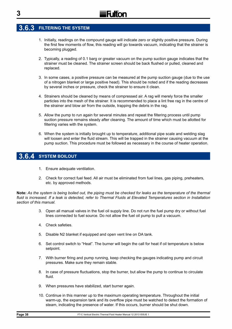
FT-C Vertical Electric Thermal Fluid Heater Manual 12 2013 ISSUE 1Page 38
3
3.6.3 FILTERING THE SYSTEM
1. Initially, readings on the compound gauge will indicate zero or slightly positive pressure. During the first few moments of flow, this reading will go towards vacuum, indicating that the strainer is becoming plugged.
2. Typically, a reading of 0.1 barg or greater vacuum on the pump suction gauge indicates that the strainer must be cleaned. The strainer screen should be back flushed or pulled, cleaned and replaced.
3. In some cases, a positive pressure can be measured at the pump suction gauge (due to the use of a nitrogen blanket or large positive head). This should be noted and if the reading decreases by several inches or pressure, check the strainer to ensure it clean.
4. Strainers should be cleaned by means of compressed air. A rag will merely force the smaller particles into the mesh of the strainer. It is recommended to place a lint free rag in the centre of the strainer and blow air from the outside, trapping the debris in the rag.
5. Allow the pump to run again for several minutes and repeat the filtering process until pump suction pressure remains steady after cleaning. The amount of time which must be allotted for filtering varies with the system.
6. When the system is initially brought up to temperature, additional pipe scale and welding slag will loosen and enter the fluid stream. This will be trapped in the strainer causing vacuum at the pump suction. This procedure must be followed as necessary in the course of heater operation.
3.6.4 SYSTEM BOILOUT
1. Ensure adequate ventilation.
2. Check for correct fuel feed. All air must be eliminated from fuel lines, gas piping, preheaters, etc. by approved methods.
3. Open all manual valves in the fuel oil supply line. Do not run the fuel pump dry or without fuel lines connected to fuel source. Do not allow the fuel oil pump to pull a vacuum.
4. Check safeties.
5. Disable N2 blanket if equipped and open vent line on DA tank.
6. Set control switch to “Heat”. The burner will begin the call for heat if oil temperature is below setpoint.
7. With burner firing and pump running, keep checking the gauges indicating pump and circuit pressures. Make sure they remain stable.
8. In case of pressure fluctuations, stop the burner, but allow the pump to continue to circulate fluid.
9. When pressures have stabilized, start burner again.
10. Continue in this manner up to the maximum operating temperature. Throughout the initial warm-up, the expansion tank and its overflow pipe must be watched to detect the formation of steam, indicating the presence of water. If this occurs, burner should be shut down.
Note: As the system is being boiled out, the piping must be checked for leaks as the temperature of the thermal fluid is increased. If a leak is detected, refer to Thermal Fluids at Elevated Temperatures section in Installation section of this manual.
FT-C Vertical Electric Thermal Fluid Heater Manual 12 2013 ISSUE 1 Page 39
3
3.6.5 PROCEDURE FOR FIRST SHUTDOWN
1. The heater system should be shut down after no more than 24 hours of operation at full operating temperature. At this time, the following maintenance items will need to be completed to meet warranty conditions.
2. While pump is still at operating temperature, align circulating pump(s) to pump manufacturer’s specifications. This should be done by means of a dial indicator.
3. Isolate Y-strainer(s) in system and clean regardless of pump suction pressure. Make sure that the temperature is low enough to handle safely or provision has been made to handle materials at high temperature. Generally, temperatures below 65°C are acceptable to perform operation with regular work gloves.
4. With piping system cooled to ambient temperature, torque all bolts on skid and throughout system to gasket manufacturer’s specifications using proper flange torquing practices such as incremental torque increases, star pattern, etc. Refer to Section 2, Installation.
5. Visually inspect all thread fittings and valve packings. Repair leaks and tighten valve packings to the point of stopping leak.
6. Upon putting unit back into operation, check all gauge readings and compare to values given to you by the start-up technician. Note any discrepancies and contact Fulton Ltd.
11. If steam is forcing thermal fluid out of the expansion tank vent, turn the heater off, but leave the pump on. This is to circulate the hot fluid through the piping without flushing the steam too quickly. Once steam and thermal fluid stop leaving the expansion tank unit, the heater can be turned on. Increase the temperature very slowly to prevent fluid from being forced out of the tank.
12. Continue bringing unit up to temperature slowly, with a temperature rise not exceeding 100°F (38°C) per hour. Do not exceed specified maximum outlet temperature. In the absence of specific information, consult the factory before proceeding.
13. Once up to temperature, check the fluid level in the expansion section by opening the high level manual test connection. If a permanent flow of fluid results when this valve is opened, and if all previous precautions have been followed, the expansion tank is too small for the capacity of the fluid in the installation. A larger tank must be installed.
14. After fifty hours of operation at operating temperature, check all flanges and connections for tightness.
FT-C Vertical Electric Thermal Fluid Heater Manual 12 2013 ISSUE 1Page 40
3
3.6.6 SEQUENCE OF OPERATION
Before firing the heater familiarise yourself on the use of the controls, lighting, and shutdown procedures.
For Gas Fired Burners
The burner is of forced design. The sequence of operation is as follows:
1) The flame programmer opens the main gas valve once stable pilot flame is established.
2) Pressure regulators on both the pilot and main gas supply, supply pressure to the proper level.
Note: Note the maximum inlet pressure rating of each regulator and supply a step-down regulator if required.
3) Combustion air is delivered by a centrifugal blower fan. An air switch monitors the pressure and is part of the flame programmer safety interlock circuit.
4) The flame programmer monitors the safe operation of the burner. Functions include pre-purge of the combustion chamber, provision of ignition via the ignition transformer and electrode, opening the pilot gas valve, monitoring the pilot flame signal via the flame sensor, opening main gas valves and providing post-purge of the combustion chamber.
The flame is monitored by a flame sensor. In the event of insufficient, unstable, or non existent pilot or main flame, the flame sensor will cause a safety lockout of the flame programmer. Safety lockout can also be caused if the flame sensor is improperly positioned or grounded. After fault has been corrected, reset by pressing the reset button on the casing of the burner control box. For On/Off Burner
The sequence of operation for the on/off burner is as follows:
1) Beginning with power on, limit switch closed, fuel valves closed, and temperature controller calling for heat, the flame programmer starts the cycle and the blower motor starts prepurge.
2) The air proving switch must be closed now. Air dampers remain in maximum position.
3) (Gas Pilot) Provided all safety interlocks are proven, ignition and pilot are energised and a timed trial for pilot ignition begins. After the pilot flame is proven, the main fuel valve is energised. Ignition is turned off when flame is registered and the main gas valves open.
4) (Spark Ignition) At the end of purge time, provided all safety interlocks are proven, the spark is on and oil valves are opened. When the flame is proven, the spark is shut off.
5) When the fluid temperature reaches the off setting (typically the setpoint plus 2 to 5 degrees) of the operating temperature controller, all fuel valves are closed.
The burner motor stops and the entire system is ready for restart on demand.
FT-C Vertical Electric Thermal Fluid Heater Manual 12 2013 ISSUE 1 Page 41
3MODULATING BURNER
The function of the flame programmer must be greatly extended in a modulated system. Along with limit controls, operating controls and interlock devices, the programmer automatically controls the operation of the burner, blower motor, ignition, main fuel valves and modulating motor (or servo motors).
The sequence of operation is as follows:
1) Beginning with power on, limit switch closed, fuel valves closed, and modulating limit controller closed and calling for heat, the flame programmer begins its cycle and the blower motor starts prepurge. The modulating circuit closes, driving the air dampers to maximum for prepurge.
2) The air flow proving switch must be closed now. After timed prepurge, the modulating motor (servo motor) drives the air damper to its low fire position. All start interlocks must be proven or the flame programmer will lockout.
3) (Units with Gas Pilot) Ignition and pilot are energised and a timed trial for pilot ignition begins. After the pilot flame is proven, ignition turns off and the main fuel valve is energised. Pilot fuel is turned off and the modulating motor
4) (Units with Spark Ignition) The spark and oil valves are energised and a timed trial for ignition begins. With the flame proven, the control advances through its main light off sequence, and the ignition shuts off. At this time, with the flame proven, the modulating motor (servo motor) is released to automatic.
5) When the modulating motor (servo motor) is released to automatic, it receives its signal from the modulating temperature controller. The modulating motor (servo motor) then drives the modulating fuel valve and air damper in proportion to the heat demand.
6) During the initial call for heat, the modulating fuel valve and air damper will drive to their full-fire position. As the temperature set point is approached, the modulating motor (servo motor) will continue to reduce the input until low-fire position is reached. Input automatically increases and decreases according to load demand.
7) When the fluid temperature reaches the set point of the temperature controller or of the optional operating limit controller, all fuel valves will close and the flame programmer will advance to the post purge cycle. When the postpurge cycle begins, the modulating motor will be in the low fire position. At the end of postpurge, the burner motor stops and the entire system is ready for restart on demand.
FT-C Vertical Electric Thermal Fluid Heater Manual 12 2013 ISSUE 1Page 42
3Oil Fired Burner
The following refers to the design and operation of the on/off burner utilising fuel oil which requires no preheating. This burner is of high pressure, mechanical atomisation design.
The sequence of operation is as follows:
1) An oil pump is used to obtain necessary atomising pressure before the fuel oil reaches the nozzle. The fuel oil is divided into fine particles in the nozzle and imparted with a rotating motion before escaping from the nozzle as a cone of finely atomised oil.
2) Combustion air is supplied by a centrifugal fan. A damper provides throttling of the inlet opening. The air from the fan reaches the burner head after going through a turbulator, accomplishing correct distribution and mixture of air and atomised fuel oil.
3) An electric spark between two electrodes provides ignition of the atomised mixture, except where code requires a gas pilot. This spark is produced by a high voltage transformer.
4) The flame programmer circuit controls normal operation of the burner. The sequence includes purging of the combustion area for a set period, ignition and opening of magnetic valves on the oil circuit; post-purge of combustion area and return to re-start position.
5) A scanner mounted on the burner casing and facing the light of the flame monitors the flame.
6) Safety lock out occurs within a preset minimum time in the event of insufficient, unstable or non- existent flame. After fault has been corrected, reset programmer by depressing the reset button on the casing of the burner control box.
7) Proper fuel pressure at the burner nozzle is essential. The correct firing rate is obtained by setting the fuel oil pump to give the design pressure for each unit. This is done at the factory. Pressure is measured by connecting a 0-25 bar (0-400 PSI) test pressure gauge to the gauge connection on the fuel pump. The fuel pressure gauge indicates the pressure of the fuel at the burner nozzle.
8) Typical pressures range between 12-22 bar (160-350 PSI). Note the correct setting upon commissioning. Modulating units should have a second pressure gauge monitoring the pressure in the return pipe from the burner. This gauge will indicate the variation of oil flow caused by modulation of the burner. Gauge readings should be recorded at start-up and checked periodically.
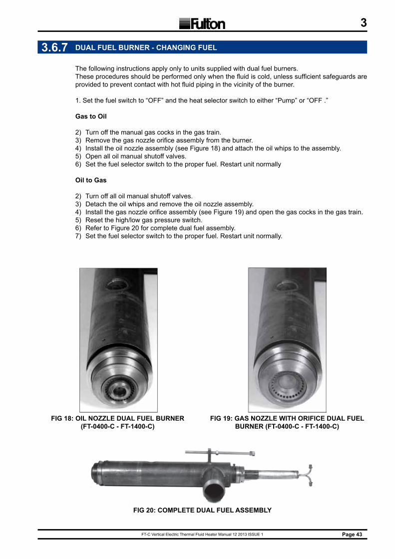
FT-C Vertical Electric Thermal Fluid Heater Manual 12 2013 ISSUE 1 Page 43
3
3.6.7 DUAL FUEL BURNER - CHANGING FUEL
The following instructions apply only to units supplied with dual fuel burners.These procedures should be performed only when the fluid is cold, unless sufficient safeguards are provided to prevent contact with hot fluid piping in the vicinity of the burner.
1. Set the fuel switch to “OFF” and the heat selector switch to either “Pump” or “OFF .”
Gas to Oil
2) Turn off the manual gas cocks in the gas train.3) Remove the gas nozzle orifice assembly from the burner.4) Install the oil nozzle assembly (see Figure 18) and attach the oil whips to the assembly.5) Open all oil manual shutoff valves.6) Set the fuel selector switch to the proper fuel. Restart unit normally
Oil to Gas
2) Turn off all oil manual shutoff valves.3) Detach the oil whips and remove the oil nozzle assembly.4) Install the gas nozzle orifice assembly (see Figure 19) and open the gas cocks in the gas train.5) Reset the high/low gas pressure switch.6) Refer to Figure 20 for complete dual fuel assembly.7) Set the fuel selector switch to the proper fuel. Restart unit normally.
FIG 20: COMPLETE DUAL FUEL ASSEMBLY
FIG 18: OIL NOzzLE DUAL FUEL BURNER (FT-0400-C - FT-1400-C)
FIG 19: GAS NOzzLE WITH ORIFICE DUAL FUEL BURNER (FT-0400-C - FT-1400-C)

FT-C Vertical Electric Thermal Fluid Heater Manual 12 2013 ISSUE 1Page 44
3
3.6.8 GAS FIRED MODULATING BURNER
SETTING PILOT
1) Verify the main burner switch is in the OFF position.
2) Supply power to the heater. The AZL will display “system test” and then move to the main menu.
3) Select PWLogin, press Enter. Select AccessServ. Press Enter. (This type of step will be shown as PWLogin > AccessServ for the remainder of this section. Enter the service passwords using the arrow key. The password is case sensitive. The case of a letter can be changed by pressing the other arrow key. (For example, if you used the right arrow key to get to the letter A, press the left arrow key to get a). After you have pressed Enter on the last character of the password, press Enter once more to accept the password. If you do not have the password, contact your Fulton Authorized Representative to perform the changes. Service=NB# or OEM=AAAA (Enter after each A).
4) Select Params&Display. Press Enter. Select Ratio Control. Press Enter. Select ProgramStop. Press Enter. Change the Program Stop to 44 Interv1 by using the arrow keys. Con! rm the change by pressing Enter. This will set the burner management system to a ‘pilot hold’ setting.
5) Verify that the current value “curr” changes to 44 Interv 1.
6) The full listing of program stops are: » 24: Air damper in the prepurge position » 32: Traveling to the FGR position » 36: Ignition position (before pilot ignition) » 44: Ignition position (after pilot ignition) » 52: Ignition position (after main burner ignition) » 72: Air damper in the postpurge position » 76: Traveling to the FGR position
7) Press Escape 4 times to get back to the main menu.
8) Under ManualOperation > Setload, change the load to 0% by using the arrow keys. Press Enter and verify the 0% has been acknowledged in the “curr” field.
9) Press Escape once to get back to the ManualOperation menu.
10) Under Auto/Manual/OFF, change the operation to Burner On by using the arrow keys. Press enter and verify that “Burner On” is acknowledged in the current field.
11) Press Escape twice to get back to the main menu.
12) Turn the main burner switch Local or On position.
13) Increase the set point. Under operation-Heater set point go to setpoint W1 using the arrow key then press Enter. Change the set point under new, using the arrows and press Enter. The new set point should appear under actual and displayed in degrees.
14) After several seconds the burner control will start its pre-ignition phase andthe blower will start.
15) You can observe the status of the burner by going to the main menu (by pressing Escape) then selecting Operational Stat > Normal Operation.
16) The unit will purge then drive to the ignition position and the pilot should light.

FT-C Vertical Electric Thermal Fluid Heater Manual 12 2013 ISSUE 1 Page 45
317) The burner control will stay at this pilot hold stage so you can inspect and adjust the pilot as
needed.
18) The pilot gas pressure should match the test fire sheet.
19) The flame signal should be greater than 90% when viewed from the top menu of the Siemens AZL display.
20) Once the pilot is adjusted properly and you are ready to light the main burner, press Escape to the main menu.
3.6.9 SETTING MAIN BURNER IGNITION
1) Under Params&Display >RatioControl >ProgramStop, change the Program Stop to 52 Interv2. This is the main burner ignition position. Press Enter and confirm that 52 Interv2 is acknowl edged in the current field. This change moves the control to the main burner ignition point in the burner sequence.
2) This will allow the main burner to ignite. Should the burner not light, the gas and air servo motors are not synchronized to produce a combustible mix.
3) Turn the ON/OFF switch on the panel box to OFF.
4) To reset the alarm: Press Escape on the AZL once. Press Enter on the AZL to reset the control. The red light should go out.
5) To change the setting, return to the front menu by pressing Escape until you are to the main menu. Then select Params&Display >RatioControl >GasSettings >SpecialPositions > Ignition Pos, adjust the gas servo position by using the arrow key to move down to Gas servo if needed. Press Enter to select the servo. Move the gas servo to its new position with the arrow keys. Press Enter to confirm the new value. Use the down arrow to move to the air servo setting if needed. Press Enter to select the servo, use the arrow keys to set the new value. Press Enter to confirm this.
6) Switch the ON/OFF switch back to ON. The heater will re-start.
7) The light off point for main flame can be set at a higher input than low fire.
8) Press Escape 6 times to get back to the main menu.
9) You can observe the status of the burner by going to OperationalStat > NormalOperation.
10) Verify that the flame signal on the display is great than 90% and check combustion. Adjust the burner to match the test fire sheet for main burner ignition. The procedure described in Setting Main Burner Ignition is used.
11) Once the ignition position has been adjusted properly, you are ready to check the burner throughout its modulation range. Press Escape twice to get back to the main menu.
FT-C Vertical Electric Thermal Fluid Heater Manual 12 2013 ISSUE 1Page 46
3
3.6.10 SETTING MAIN RUN MODULATION
1) Upon releasing the heater to main run modulation, the heater will drive to low fire.
2) It is necessary to set/check combustion through the entire range of modulation first to enable high fire to be reached. Once high fire is achieved, the incoming gas pressure can be set (if required). Fine-tuning of the servo setting throughout the range should be performed only once high fire settings are confirmed.
3) If the burner loses flame while driving to a point then: » Turn the main ON/OFF switch to OFF. » Reset the loss of flame fault. » Press Escape on the AZL once. » Press Enter on the AZL to reset the control. The red light on the panel box door should go out. Adjust the air and gas servos for that point while the burner is off. » Follow steps below. » Turn the main ON/OFF switch to ON.
4) Under Params&Display >RatioControl >GasSettings >ProgramStop, change the program stop to deactivated by using the arrow keys. Confirm that ‘deactivated’ is acknowledged in the current field.
5) This change will allow the burner to modulate. The burner will now drive to low fire. Remember, it is only important at this stage to set low fire to be stable and with clean combustion. Exact setting is to be performed once high fire is confirmed.
6) Press Escape 5 times to get back to the main menu.
7) You can observe the status of the burner by going to OperationalStat/NormalOperation.
8) Verify the flame signal on the display, measure input if gas meter is available. If not, match last elbow pressures and combustion for test fire sheet. Adjust the burner as needed.
3.6.11 SETTING LOW FIRE
Note: As soon as a servo position is altered, the servo will move to that position. Only change servo settings by a maximum of 0.5° at a time before verifying combustion.
1) Go to Params&Display >RatioControl >GasSettings>CurveParams.
2) Wait for the spinning line on the left to disappear. Press Enter. The number 1 should appear to the right of the cursor, this is the Point Number.
3) Press Enter once. Select ChangePoint by pressing the arrow keys to highlight and then press Enter to select. This will cause the servo motors to move to this low fire point.
4) Check combustion and adjust the servo motors as required. To adjust a servo motor, arrow to it and press Enter. Then adjust the setting as required and press Enter. You can now adjust another servo motor if needed.
5) When combustion is properly set for that point, press Escape. If it asks you to store the point, press Enter. Note the AZL will only ask to save if either servo value has been altered.
6) Low fire is now set and stored.

FT-C Vertical Electric Thermal Fluid Heater Manual 12 2013 ISSUE 1 Page 47
3
3.6.12SETTING THE COMPLETE RANGE
1) Remember it is only necessary to approximate the setting through the modulation range until high fire conditions are established.
2) Press Enter once more to have access to the point number field. Increase the point number by one and press Enter. Select ChangePoint and press Enter. The servos will now move to that point.
3) Verify combustion is satisfactory.
4) Measure input or monitor last elbow pressure. Verify that these points are in general correspondence with the test fire sheet. Repeat step 2 until the point position has a load value of 100%.
5) You are now at high fire. Verify combustion is per test fire sheet.
6) Once at high fire, adjust the incoming gas pressure at the main gas regulator to match the test fire report. Adjust the gas servo motor to change the last elbow pressure to match the test fire report.
7) Adjust the air servo motor to adjust the emissions as needed.
8) Repeat step 2 but start at the high fire point number. Continually decrease the point number after combustion has been verified at each point.
9) Once all the points have been verified, press Escape until you are back to the main menu.
10) You can observe the status of the burner by going to OperationalStat>NormalOperation.
11) Turn the main ON/OFF switch to OFF. The control will now postpurge. Verify ignition using steps from Setting Main Burner Ignition with the new gas pressures.
12) Turn the main burner switch to OFF. The control will now post purge.
13) Under Manual Operation > Auto/Manual/OFF , change the operation to Automatic and press Enter and confirm Automatic is entered in the current field.
14) Press Escape twice to get back to the main menu.
15) Under Updating >ParamBackup, select LMV51 – AZL. This will store all of the adjustments that have been made in the LMV base module to the display. If the base module fails in the future, the display can be used to download all of the parameters into a new base module.
16) The heater is now ready to run. Adjust your setpoint on the temperature control to the desired temperature and turn the main ON/OFF switch to ON for the burner to operate.
FT-C Vertical Electric Thermal Fluid Heater Manual 12 2013 ISSUE 1Page 48
3
3.6.13 CHANGING SET POINT ON THE AzL
1) Hit Escape to Select Operation than hit Enter and scroll to Heater Set point, hit Enter to Set point W1 hit Enter and enter new set point with Select buttons.
2) When accomplished hit Enter than Escape 3 times to Operational Stats hit Enter to Normal Operation, hit Enter to get to the main screen.
3.6.14FOR MANUAL OPERATION
1) Hit Escape and scroll to Manual, hit Enter to Auto / Manual / OFF , change to Manual and hit escape to Set Load, change to 0 or desired load range with the select buttons.
2) When in Manual it will allow you to go to any load range to verify combustion.
3) When done hit Escape and scroll to Operational Stats, hit Enter to Normal Operation, hit Enter to main screen.
4) To return back to Auto operation repeat step 1 & 2.
5) Please refer to this manual’s addendum for information on specific LMV 51 control parameters.
Note: DO NOT leave unit unattended in Manual Operation, in this mode the LMV 51 will ignore its internal Set Point.
3.7 REQUIRED PRESSURE DROP ACROSS THE HEATER
1. The thermal fluid pressure drop across your heater is critical. This should be recorded at the completion of start-up. The pressure drop value is obtained by subtracting the heater outlet pressure from the heater inlet pressure when the thermal fluid is at normal operating temperature.
2. At the recommended standard flow rates, and 0.7 sp gr, the pressure drop across the heater should be as shown in the chart in section 3.8.
3. In the event of an abnormal reading, contact the Fulton service department immediately. Failure to take immediate action in the event of reduced fluid flow may result in rapid and serious degradation of the fluid, with possible damage to the heater.
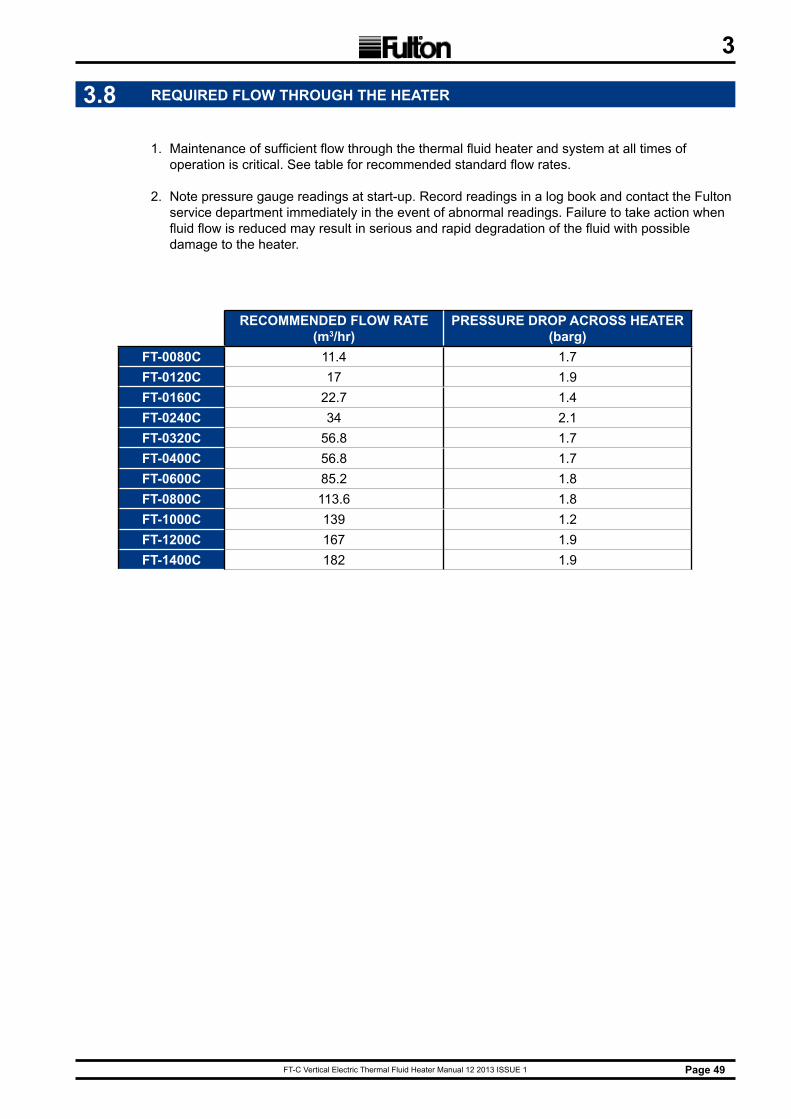
FT-C Vertical Electric Thermal Fluid Heater Manual 12 2013 ISSUE 1 Page 49
3
3.8 REQUIRED FLOW THROUGH THE HEATER
1. Maintenance of sufficient flow through the thermal fluid heater and system at all times of operation is critical. See table for recommended standard flow rates.
2. Note pressure gauge readings at start-up. Record readings in a log book and contact the Fulton service department immediately in the event of abnormal readings. Failure to take action when fluid flow is reduced may result in serious and rapid degradation of the fluid with possible damage to the heater.
RECOMMENDED FLOW RATE (m3/hr)
PRESSURE DROP ACROSS HEATER (barg)
FT-0080C 11.4 1.7FT-0120C 17 1.9FT-0160C 22.7 1.4FT-0240C 34 2.1FT-0320C 56.8 1.7FT-0400C 56.8 1.7FT-0600C 85.2 1.8FT-0800C 113.6 1.8FT-1000C 139 1.2FT-1200C 167 1.9FT-1400C 182 1.9
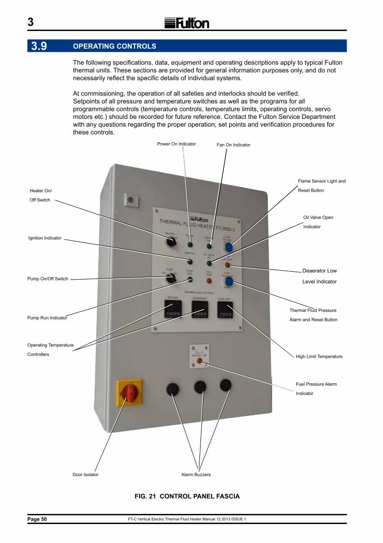
FT-C Vertical Electric Thermal Fluid Heater Manual 12 2013 ISSUE 1Page 50
3
3.9 OPERATING CONTROLS
The following specifications, data, equipment and operating descriptions apply to typical Fulton thermal units. These sections are provided for general information purposes only, and do not necessarily reflect the specific details of individual systems.
At commissioning, the operation of all safeties and interlocks should be verified.Setpoints of all pressure and temperature switches as well as the programs for all programmable controls (temperature controls, temperature limits, operating controls, servo motors etc.) should be recorded for future reference. Contact the Fulton Service Department with any questions regarding the proper operation, set points and verification procedures for these controls.
FIG. 21 CONTROL PANEL FASCIA
Alarm Buzzers
Power On Indicator
Flame Sensor Light and
Reset Button
Oil Valve Open
Indicator
Deaerator Low
Level Indicator
Fan On Indicator
Thermal Fluid Pressure
Alarm and Reset Button
High Limit Temperature
Fuel Pressure Alarm
Indicator
Door Isolator
Heater On/
Off Switch
Ignition Indicator
Operating Temperature
Controllers
Pump Run Indicator
Pump On/Off Switch
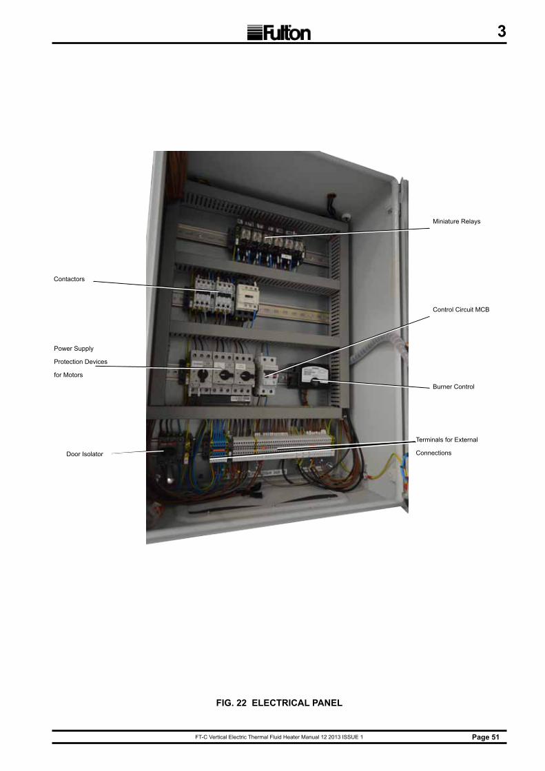
FT-C Vertical Electric Thermal Fluid Heater Manual 12 2013 ISSUE 1 Page 51
3
FIG. 22 ELECTRICAL PANEL
Miniature Relays
Control Circuit MCB
Burner Control
Terminals for External
Connections
Contactors
Power Supply
Protection Devices
for Motors
Door Isolator
FT-C Vertical Electric Thermal Fluid Heater Manual 12 2013 ISSUE 1Page 52
3
3.9.1 LIQUID LEVEL SWITCH-WHEN COMBINATION TANK IS SUPPLIED
Adhere to the following:1. Locate the liquid level switch and install prior to operation of the equipment. The liquid level
switch is wired to the main heater panel. Failure to “make” this switch will result in lack of power at the panel.
2. In the event of system fluid loss, the level in the expansion section of the combination tank will drop, and the liquid level switch will shut the unit down. Control power will be lost to the panel.
3. To confirm operation, manually trip the liquid level switch. Unit should shut down; pump will stop.
3.9.2 AIR SAFETY SWITCH
1. The air safety switch is installed in the heater panel and is connected by tubing to the blower outlet. This switch requires that the blower fan deliver combustion air before energizing any fuel valves.
2. While firing, disconnect the copper line from the fitting in the top cover of the air switch. The burner should shut down. Attempt to restart the unit by resetting the flame programmer.
3. Blower motor will start, but firing sequence should not begin.
4. Lockout of LMV will occur.
3.9.3 BLOWER MOTOR STARTER
Note: For units equipped with manual trip test button or motor starter.
1. While firing, actuate the manual trip button on blower motor starter. Unit should lock out. Attempt re-start by resetting the flame programmer. Purge cycle will not begin.
2. Reset motor starter; blower should start and purge cycle will begin.
3. Lockout of LMV will occur.
FT-C Vertical Electric Thermal Fluid Heater Manual 12 2013 ISSUE 1 Page 53
3
3.9.4 DIFFERENTIAL PRESSURE SWITCH
The differential pressure switch is mounted to the heater. Sensing lines connect this switch to both the inlet and outlet manifold of the heater. This switch is critical and ensures proper flow through the heater at all times.
1. Proper setpoint is 0.14 barg below the published differential pressure of the heater.
Note: The differential pressure will vary with heater model.
2. The heater is dependent on proper flow for operation; therefore, a differential pressure switch is used to sense the pressure drop across the heater. The differential pressure switch will shut the unit down in the event of loss of flow.
3. The differential pressure switch can be tested while only the pump is running at operating temperature. Remove the metal cover on top of the switch and increase the setpoint until the pump shuts down. This value should be greater than the DP of the gauges. Next, decrease the setpoint back to its initial value and depress the pump start button to verify the pump will re-start.
3.9.5 PUMP MOTOR STARTER
If a pump starter is supplied the pump motor starter will be located in the heater panel or pump skid. When the pump start button is pushed, the pump motor starter will engage the pump.
1. While firing, actuate the manual trip button on the pump motor starter.
2. Pump and burner will shut down.
3. The blower should continue to run for approximately 30 secods.
4. Attempt to restart pump by depressing the pump start push button.
5. The pump should not start. Reset starter and start pump.
FT-C Vertical Electric Thermal Fluid Heater Manual 12 2013 ISSUE 1Page 54
3
3.9.7 GAS PRESSURE SWITCH
3.9.6 HIGH AND LOW FLUID PRESSURE SWITCHES
The heater is equipped with a low inlet, high inlet and high outlet pressure switch. See Figure 6. The switches are located on the side of heater panel with tubing connections to the respective heater inlet and outlet manifolds. The switches are used to ensure proper flow through the heater (no restrictions in the piping system). The switches must be set at startup and the setpoints are based on the system design/performance. The only pressure required in the thermal fluid system is the pressure required to maintain the proper flow. Pressure changes are monitored with these switches, which will shut the unit down in case of a change in the fluid flow.
To Test The Switches1. With three position switch set to “Pump”, remove the cover from the pressure switch and
manally trip the switch. Pump should shut down.
2. Repeat for each switch; replace covers. Note, if the burner was on, it would also stop.
3. To set the inlet low fluid pressure cutout switch, raise the setpoint with the fluid at operating temperature and pump running, until the pump shuts down. Note the setpoint and lower by 0.7 barg, then restart pump. The setpoint at cutout should correspond to the reading on the inlet pressure gauge.
4. With the unit cold and pump running, lower the high fluid pressure cutout switch until the pump shuts down. Note the setpoint and raise by 10 PSI, then re-start pump. The setpoint at cutout should correspond to the inlet gauge reading.
5. With the unit running at operating temperature, lower the high outlet pressure switch until the pump shuts down. Note the setpoint and raise by 0.7 barg, then restart the pump. The setpoint of this switch should correspond to the outlet pressure gauge reading.
Note: Switch settings shall never exceed the safety valve set pressure.
Note: Gas Fired Units Only
The high and low gas pressure switches are located on the gas train See Figure 24. The switches are used to ensure that the incoming gas pressure and gas pressure to the burner are within the appropriate range.
1. While firing, shut the main gas ball valve closest to the burner.
2. Unit will lock out on high gas pressure.
3. Attempt restart by resetting flame programmer.
4. Unit will start purge and lock out.
5. Open the gas valve closest to the burner and reset flame programmer.
6. Reset high side of switch, unit will start purge and fire.
7. To test the low gas pressure switch, close the incoming manual valve.
8. Allow the control to sequence.
9. When the gas valves energize, the heater should lock out.
10. Reset the low side of the switch/reset flame programmer and open the upstream manual valve.
11. The unit will start purge and fire.
FT-C Vertical Electric Thermal Fluid Heater Manual 12 2013 ISSUE 1 Page 55
3
3.9.8 OPERATING TEMPERATURE CONTROL
The Coil Design unit is a fired heat exchanger and the safe control and monitoring of the thermal fluid temperature is of vital importance. The safe maximum temperature of the fluid must be strictly adhered to.
a) The safe maximum temperature of the fluid must be strictly adhered to.
b) When consulting fluid manufacturer’s literature for the safe maximum fluid temperature, note that the temperatures quoted are the actual limit to which any of the fluids may be subjected. It is important to remember that in any fired heater there exists a “film” temperature which is higher than the temperature of the bulk of the fluid.
c) Temperature controllers measure the bulk temperature and not the film temperature. This must be taken into consideration when setting the temperature controls.
d) These approximate guidelines for temperature settings are not to override the system design parameters.
e) These instructions should be used with information from the system designer. Manufacturer’s literature on the temperature controller is provided in the last section of this manual.
f) Standard primary temperature control sensing point location for On/Off and Modulating heaters is on the heater outlet.
g) When optional inlet location of the primary controls is specified. the following instructions may still be used with some modification. For instance when primary controls are located on the inlet, the dead band range will be much narrower than on heaters with outlet control. In addition, temperature changes will not be as immediately apparent.
h) An indicating temperature controller is used to regulate the thermal fluid temperature. Typically the indicating control is a thermocouple.
j) The thermocouple is directly immersed in the thermal fluid in the heater. The setpoint of the controller is regulated by the keypad.
k) The operating temperature should be set at least 10°C lower than the high limit temperature.
3.9.9 HIGH LIMIT TEMPERATURE CONTROL
a) All units are fitted with high temperature limit controllers which monitor the fluid temperature in the heater. This limit controller provides over temperature protection. A high temperature limit switch acts as an over temperature safety device. If the high temperature limit shuts down the unit, the manual reset button on the limit switch must be pressed.
b) The high temperature limit controller is factory set to 280°C.
c) Several consecutive lockouts caused by the high temperature limit controller indicate the need for immediate installation review, beginning with fluid level in the expansion tank, firing rate, and circulating pump performance.
The High Temperature Reset button will need to be pressed to re-activate the system once the thermal fluid temperature has fallen below the ‘high limit’.
This must be set to the lowest of the following:» Maximum operating temperature of the fluid.» Maximum operating temperature of the equipment.» 15°F (9°C) over maximum system operating temperature.

FT-C Vertical Electric Thermal Fluid Heater Manual 12 2013 ISSUE 1Page 56
3
3.9.10 PRESSURE GAUGES
a) All units have two pressure gauges measuring the thermal fluid pressure at the inlet of the heater and at the outlet of the heater. A third gauge measures the pump suction pressure.
b) The difference between the readings of the two gauges indicates the pressure loss across the heater. The difference must not fall below the recommended value. Recommendations are based on heater size and are listed in the Technical Information Sheet. (see Section 5)
c) The gauge indicating the pressure of the fluid at the inlet is labelled “Inlet“. The “Outlet” gauge indicates the pressure at the outlet, and in effect indicates the resistance of the external pipework circuit. The pressure gauge indicating pressure at the inlet of the pump is labelled “Suction .”
3.9.11 OPERATING LIMIT CONTROLLER
The limit controller is mounted in the panel box door. This limit controller senses temperature in the outlet manifold. The temperature setpoint in the controller may be adjusted per manufacturer’s instructions.
3.9.12 ON/OFF CONTROLS
Typically one controller is provided to sense the temperature on the heater outlet. This controls the operation of the heater by switching it on and off.
1. An adjustable two point differential between shut off and start up is built into the controller. This prevents frequent cycling of the burner. The controller is set to provide the desired outlet fluid temperature. Due to the temperature rise through the unit, this may be considerably higher than the inlet temperature.
2. If the unit is equipped with an on/off controller, it will be located on the face of the electrical cabinet. The temperature setpoint in the controller can be adjusted following the manufacturer’s instructions.
3.9.13 FLOW PROVING DEVICE
The heater is dependent on proper flow for operation; therefore, up to three pressure switches and a differential pressure switch are used to sense flow across the heater. Any one of these switches will shut the unit down in the event of loss of flow.
The Liquid Flow indicator illuminates when there is sufficient flow across the heater.
FT-C Vertical Electric Thermal Fluid Heater Manual 12 2013 ISSUE 1 Page 57
3
3.9.14 TEST OF IGNITION SAFETY SYSTEM SHUTOFF
Test the ignition system safety shutoff as follows:
1. Shut the pilot ball valve.
2. Close the last gas valve between the inlet to the burner and the butterfly valve.
3. With the main gas cock (inlet manual gas valve) open, the burner should be cycled on. After all the safety limits such as gas pressure and temperature are satisfied, the blower will run and pre-purge the heater.
4. Once the purge is complete (30 seconds), the ignition transformer will be energized. There will be a 4 second trial for ignition period. During this period, indicator lights on the flame safeguard (pilot and main).
5. With no flame established, the flame safeguard will not receive a flame signal from the scanner.
6. After 4 seconds, the flame safeguard programmer will assume a “Flame Failure” condition and go to a “lockout” mode. Lockout will require manual reset of the flame safeguard.
7. After completing this test, open the gas valve.
3.9.15 CYCLE TESTING
The heater should be cycled tested and automatically allowed to go through its normal starting sequence several times to verify that all components are functioning properly. This will also verify that combustion is set properly so that heater light off has a smooth transition from ignition to main flame.
A minimum of 10 cycles should be met without any flame failures, with combustion readings comparable to the factory test fire sheet and no interlocks causing the heater to shutdown.
FT-C Vertical Electric Thermal Fluid Heater Manual 12 2013 ISSUE 1Page 58
3
3.11 DAILY SHUTDOWN
1. Switch the burner off.
2. Allow the fluid to circulate for approximately 20-30 minutes and then switch off the circulation pump.
3. When using a fluid cooled pump, continue to circulate cooling water to the pumps for 30 minutes after stopping circulation.
4. Open the power supply switches.
5. Units switched off by an automatic time switch should have an extra relay fitted to allow 20-30 minutes of fluid circulation after stoppage in order to prevent localised over heating of fluid.
6. Close fuel valves if required. Closing of system valves is not generally necessary unless maintenance of components requires a partial draining of the system.
7. Because of the high temperatures usually applied, leaks are not expected to occur when cool down is achieved, provided pipework is free to contract naturally when cold.
3.10 DAILY START-UP
1. Check positioning of all system valves to ensure flow is not dead-headed.
2. Visually check relative position of minimum level float switch in the combination tank.
3. Turn on power supply switches.
4. Where applicable, open water cooling valve and check that water flows correctly. (For water cooled pumps only.)
5. Start the circulation pump and monitor the pressure gauges on heater.
6. Push reset on the high fluid pressure switch located on the side of the control panel.
7. When ready to begin heating, switch the burner on. After a short delay resulting from the purge period, the burner will ignite. Make sure the temperature set point is as desired.
8. Start-up is considered complete when the unit begins to throttle back or shutdown on target temperature.
9. On gas units, pilot valve activation will be indicated after pre-purge cycle has completed, followed by main flame activation. Check the presence of the flame by observing flame signal strength from flame programmer or testing device. Operator attendance during warm-up is a recommended precaution.
10. Start-up is considered complete when the unit begins to throttle back or shutdown on target temperature.
FT-C Vertical Electric Thermal Fluid Heater Manual 12 2013 ISSUE 1 Page 59
4
SECTION 4 - MAINTENANCEFulton recommends that these tests and checks are carried out on a regular basis to ensure that the heater is operating safely.Tests should be carried out by a competent person trained to perform such tests. If any test shows that the equipment is not operating correctly, the fault should be investigated and corrected before the boiler is used.Any rectification or repairs should be carried out by trained, competent service personnel. Appropriate training and instructions are available from Fulton Ltd - (0117) 972 3322.
4.1 REQUIRED MAINTENANCE AT FIRST SHUTDOWN
1. The thermal fluid system should be shut down after no more than 24 hours of operation at operating temperature. At this time, the following maintenance items will need to be completed to meet the condition of warranty.
2. While the pump is still at operating temperature, align circulating pump(s) to pump manufacturer specifications. This should be done by means of a dial indicator.
3. Isolate Y-strainer(s) in the system and clean regardless of the pump suction pressure. Make sure that the temperature is low enough to handle safely or provision has been made to handle materials at high temperature. Generally, temperatures below 65°C are acceptable to perform operation with regular work gloves.
4. With piping system at ambient temperature, torque all bolts on the skid and throughout the system to the gasket manufacturer’s specification using proper flange torquing practices (incremental torque increases, star-pattern, etc). These values are available in the installation section of the manual.
5. Visually inspect all thread fittings and valve packings. Repair any leaks by tightening valve packings to the point of stopping the leak.
6. Upon putting the unit back in operation, check all the gauge readings and compare to the values given to you by the start up technician. Note any discrepancies and contact the manufacturer.
4.2.1 LUBRICATION
a) Different motor manufacturers recommend various intervals for lubrication schedules. Load variations will dictate the frequency and amount of lubrication required.
b) When developing your lubrication schedule, consider the thermal fluid pump and all system pumps.
c) If you have a thermal fluid circulating pump with a packed seal, the condition of the pump packing should be checked regularly. If fluid leakage increases, tighten the packing a ¼ turn daily.
4.2 MAINTENANCE PROCEDURES
If your vessel inspection indicates severe sooting, the following procedure shouldbe followed:
1. Remove the burner and lower access doors.2. Remove the top plate, then remove gasket.3. Wire brush flue passages and use compressed air where accessible.4. Vacuum loose soot where accessible.5. Reinstall the burner and all access doors.6. Fire the heater and set combustion.
4.2.2 SOOT CLEANING
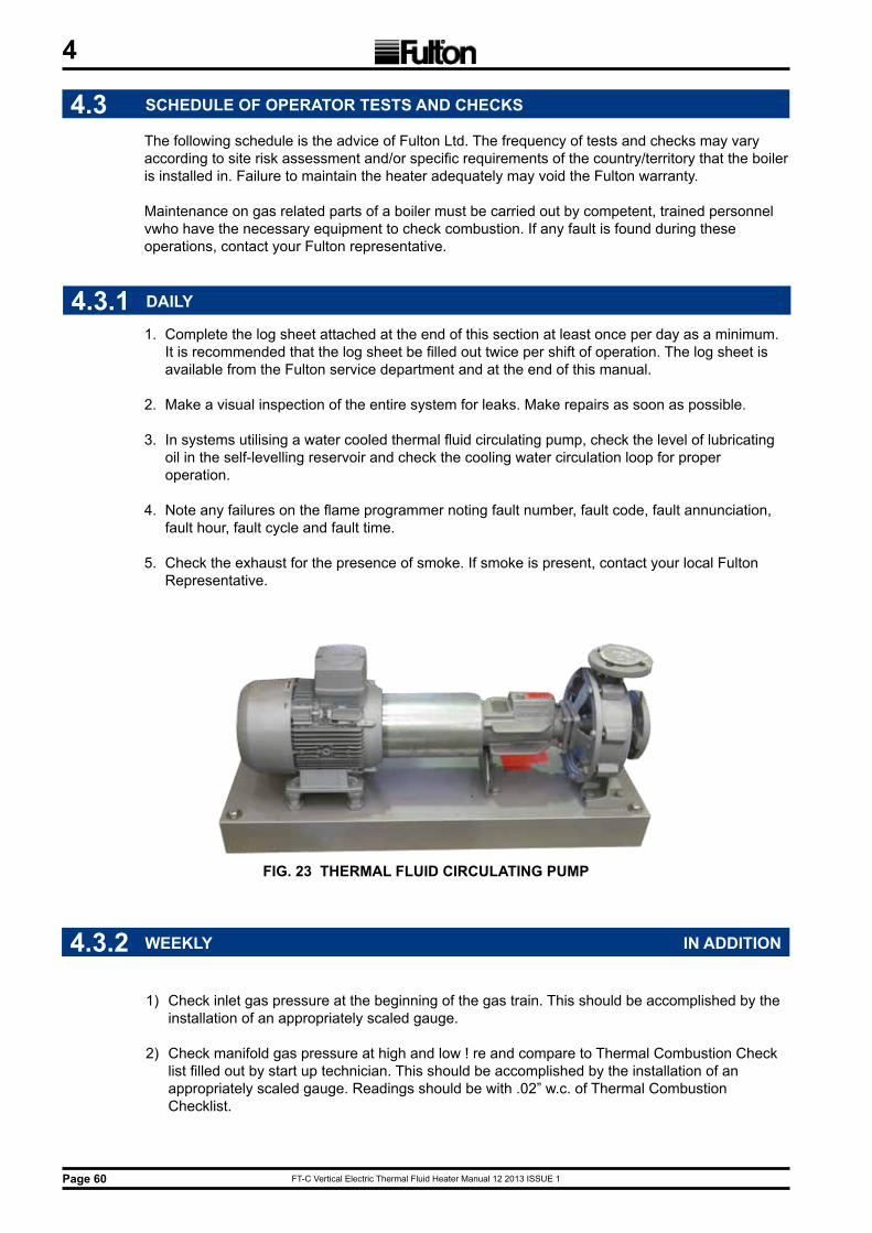
FT-C Vertical Electric Thermal Fluid Heater Manual 12 2013 ISSUE 1Page 60
4
4.3 SCHEDULE OF OPERATOR TESTS AND CHECKS
The following schedule is the advice of Fulton Ltd. The frequency of tests and checks may vary according to site risk assessment and/or specific requirements of the country/territory that the boiler is installed in. Failure to maintain the heater adequately may void the Fulton warranty.
Maintenance on gas related parts of a boiler must be carried out by competent, trained personnel vwho have the necessary equipment to check combustion. If any fault is found during these operations, contact your Fulton representative.
4.3.1 DAILY
1. Complete the log sheet attached at the end of this section at least once per day as a minimum. It is recommended that the log sheet be filled out twice per shift of operation. The log sheet is available from the Fulton service department and at the end of this manual.
2. Make a visual inspection of the entire system for leaks. Make repairs as soon as possible.
3. In systems utilising a water cooled thermal fluid circulating pump, check the level of lubricating oil in the self-levelling reservoir and check the cooling water circulation loop for proper operation.
4. Note any failures on the flame programmer noting fault number, fault code, fault annunciation, fault hour, fault cycle and fault time.
5. Check the exhaust for the presence of smoke. If smoke is present, contact your local Fulton Representative.
FIG. 23 THERMAL FLUID CIRCULATING PUMP
4.3.2 WEEKLY IN ADDITION
1) Check inlet gas pressure at the beginning of the gas train. This should be accomplished by the installation of an appropriately scaled gauge.
2) Check manifold gas pressure at high and low ! re and compare to Thermal Combustion Check list filled out by start up technician. This should be accomplished by the installation of an appropriately scaled gauge. Readings should be with .02” w.c. of Thermal Combustion Checklist.

FT-C Vertical Electric Thermal Fluid Heater Manual 12 2013 ISSUE 1 Page 61
4
4.3.4 SIX MONTHLY IN ADDITION
1. Pull burner and inspect for heat stress or soot. Clean or replace as necessary.
2. Inspect pilot tube assembly and ignition electrode. Clean or replace if necessary. Reset ignition settings to manual specifications.
3. Inspect internal surfaces of the heater. Inspect refractory for cracks. Cracks larger than ¼” wide will require repair or replacement of the refractory. Inspect coil for sooting. If soot is present, it can be removed by utilizing a brush or compressed air for light sooting. See Soot Cleaning section of this manual.
4. Have combustion checked for efficiency.
5. Review daily log sheets noting any deviations from the norm.
4.3.3 MONTHLY IN ADDITION
1. Clean fuel filters.
2. Check burner blower. Clean if necessary.
3. Clean or change air filter if applicable.
4. Manually check fluid level in the expansion tank. Drain 2 litres of thermal fluid from the expansion tank. If water is present, continue to drain 2 litres at a time until no water is present.
5. Check operation of all safeties. Refer to the instructions at the end of this section.
6. With the burner running, remove or disconnect the flame detection device. The flame programmer should lockout within 3 seconds.
7. Review daily log sheets noting any deviations from the norm.
8. Check the tightness of all couplings, including the fuel oil pump drive (oil-fired units), fan impeller, circulating pump, etc. See Figure 24
FIG 24 PUMP COUPLING
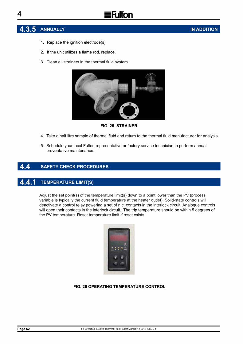
FT-C Vertical Electric Thermal Fluid Heater Manual 12 2013 ISSUE 1Page 62
4
4.3.5 ANNUALLY IN ADDITION
1. Replace the ignition electrode(s).
2. If the unit utilizes a flame rod, replace.
3. Clean all strainers in the thermal fluid system.
FIG. 25 STRAINER
4. Take a half litre sample of thermal fluid and return to the thermal fluid manufacturer for analysis.
5. Schedule your local Fulton representative or factory service technician to perform annual preventative maintenance.
4.4.1 TEMPERATURE LIMIT(S)
Adjust the set point(s) of the temperature limit(s) down to a point lower than the PV (process variable is typically the current fluid temperature at the heater outlet). Solid-state controls will deactivate a control relay powering a set of n.c. contacts in the interlock circuit. Analogue controls will open their contacts in the interlock circuit. The trip temperature should be within 5 degrees of the PV temperature. Reset temperature limit if reset exists.
FIG. 26 OPERATING TEMPERATURE CONTROL
4.4 SAFETY CHECK PROCEDURES

FT-C Vertical Electric Thermal Fluid Heater Manual 12 2013 ISSUE 1 Page 63
4
4.4.2 AIR SWITCH
Remove the ¼” copper tubing from the bottom of the air switch with the fan running. Air switch should trip the interlock circuit. Re-attach copper tubing and reset the programmer.
4.4.2.1 AIR FILTER BOX SWITCH
With heater running at high fire, block opening to air filter box by 50%. Slowly close off further until switch trips. Air filter switch should trip at just over 50% blockage.Monitor combustion valves during this procedure.
4.4.3 LIQUID LEVEL SWITCH
Manually turn the liquid level switch cam anti-clockwise. The micro-switch will open the contacts and control voltage will be lost. Release the cam and the micro-switch will make and control voltage will be restored.
4.4.4 DIFFERENTIAL PRESSURE SWITCH
With the circulating pump running, observe the difference in pressure between the heater outlet gauge and the heater inlet gauge. Remove the top cover of the differential pressure switch. Note the original setting of the switch and turn adjustment knob clockwise until the switch trips. The pointer on the switch should be within 0.15 barg of the observed pressure difference. Reset the switch to the original set point.
FIG. 28 DIFFERENTIAL PRESSURE SWITCH
Differentialpressure
switch
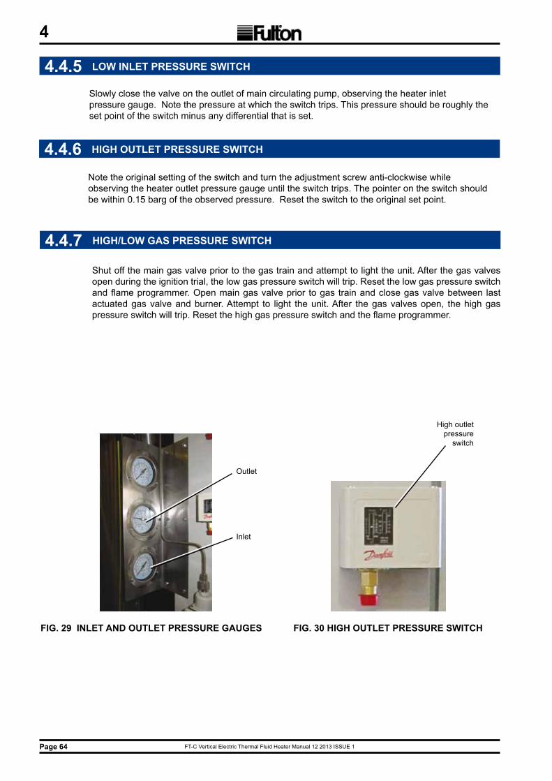
FT-C Vertical Electric Thermal Fluid Heater Manual 12 2013 ISSUE 1Page 64
4
4.4.5 LOW INLET PRESSURE SWITCH
Slowly close the valve on the outlet of main circulating pump, observing the heater inlet pressure gauge. Note the pressure at which the switch trips. This pressure should be roughly the set point of the switch minus any differential that is set.
4.4.6 HIGH OUTLET PRESSURE SWITCH
Note the original setting of the switch and turn the adjustment screw anti-clockwise while observing the heater outlet pressure gauge until the switch trips. The pointer on the switch should be within 0.15 barg of the observed pressure. Reset the switch to the original set point.
FIG. 29 INLET AND OUTLET PRESSURE GAUGES FIG. 30 HIGH OUTLET PRESSURE SWITCH
High outletpressure
switch
Outlet
Inlet
4.4.7 HIGH/LOW GAS PRESSURE SWITCH
Shut off the main gas valve prior to the gas train and attempt to light the unit. After the gas valves open during the ignition trial, the low gas pressure switch will trip. Reset the low gas pressure switch and flame programmer. Open main gas valve prior to gas train and close gas valve between last actuated gas valve and burner. Attempt to light the unit. After the gas valves open, the high gas pressure switch will trip. Reset the high gas pressure switch and the flame programmer.
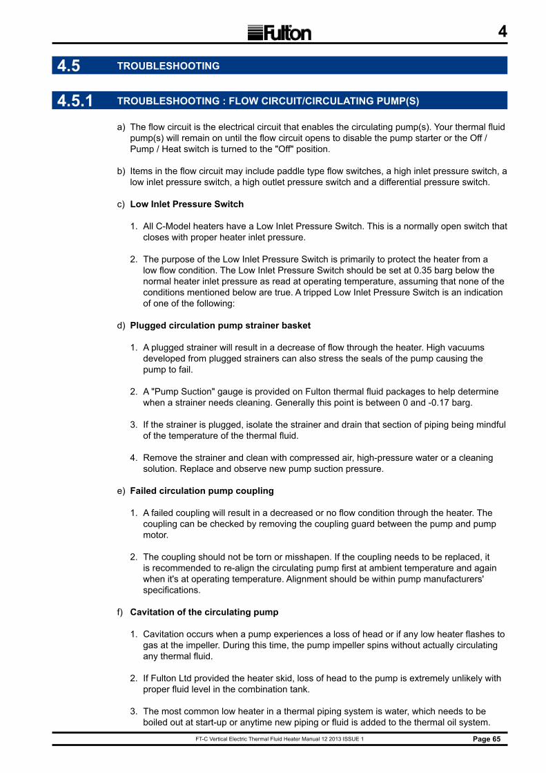
FT-C Vertical Electric Thermal Fluid Heater Manual 12 2013 ISSUE 1 Page 65
4
4.5 TROUBLESHOOTING
4.5.1 TROUBLESHOOTING : FLOW CIRCUIT/CIRCULATING PUMP(S)
a) The flow circuit is the electrical circuit that enables the circulating pump(s). Your thermal fluid pump(s) will remain on until the flow circuit opens to disable the pump starter or the Off / Pump / Heat switch is turned to the "Off" position.
b) Items in the flow circuit may include paddle type flow switches, a high inlet pressure switch, a low inlet pressure switch, a high outlet pressure switch and a differential pressure switch.
c) Low Inlet Pressure Switch
1. All C-Model heaters have a Low Inlet Pressure Switch. This is a normally open switch that closes with proper heater inlet pressure.
2. The purpose of the Low Inlet Pressure Switch is primarily to protect the heater from a low flow condition. The Low Inlet Pressure Switch should be set at 0.35 barg below the normal heater inlet pressure as read at operating temperature, assuming that none of the conditions mentioned below are true. A tripped Low Inlet Pressure Switch is an indication of one of the following:
d) Plugged circulation pump strainer basket
1. A plugged strainer will result in a decrease of flow through the heater. High vacuums developed from plugged strainers can also stress the seals of the pump causing the pump to fail.
2. A "Pump Suction" gauge is provided on Fulton thermal fluid packages to help determine when a strainer needs cleaning. Generally this point is between 0 and -0.17 barg.
3. If the strainer is plugged, isolate the strainer and drain that section of piping being mindful of the temperature of the thermal fluid.
4. Remove the strainer and clean with compressed air, high-pressure water or a cleaning solution. Replace and observe new pump suction pressure.
e) Failed circulation pump coupling
1. A failed coupling will result in a decreased or no flow condition through the heater. The coupling can be checked by removing the coupling guard between the pump and pump motor.
2. The coupling should not be torn or misshapen. If the coupling needs to be replaced, it is recommended to re-align the circulating pump first at ambient temperature and again when it's at operating temperature. Alignment should be within pump manufacturers' specifications.
f) Cavitation of the circulating pump
1. Cavitation occurs when a pump experiences a loss of head or if any low heater flashes to gas at the impeller. During this time, the pump impeller spins without actually circulating any thermal fluid.
2. If Fulton Ltd provided the heater skid, loss of head to the pump is extremely unlikely with proper fluid level in the combination tank.
3. The most common low heater in a thermal piping system is water, which needs to be boiled out at start-up or anytime new piping or fluid is added to the thermal oil system.
FT-C Vertical Electric Thermal Fluid Heater Manual 12 2013 ISSUE 1Page 66
4
4. Once the system has been brought up to full operating temperature, assuming that the entire system has seen flow, there should be no further occurrence of low heater contamination apart from possible heat exchanger failure.
g) System is Open
1. Lack of back-pressure. If control valving is improper or pressure drop across the system is too low, the resulting minimal back-pressure may not provide enough resistance for the flow to make the pressure switch. Check the thermal fluid system for proper operation of control valves.
h) Blocked sensing line on pressure switch
1. A blocked sensing line will give an inaccurate pressure reading to the pressure switch. A blocked line will need to be replaced or cleaned. Most installations have block valves at the heater to facilitate safe isolation and cleaning of the sensing line.
j) Improper switch setting
1. The Low Inlet Pressure Switch should be set at 0.35 barg less than the pressure read on the heater inlet pressure gauge at full operating temperature of the system.
k) Faulty Switch
1. If the pressure is verified and reads correctly above the set point on the switch and the sensing line to the pressure switch is open, the pressure switch is faulty. Replace the switch, set for the desired set point and test for proper operation.
l) High Outlet Pressure Switch
1. All C-Model heaters have a High Outlet Pressure Switch. This is a normally closed switch that opens with excessive heater outlet pressure.
2. The purpose of the High Outlet Pressure Switch is primarily to protect the heater from building too much pressure. Typical heaters have a maximum working pressure of 10.34 barg with 6.9 barg safety valve(s) on the heater outlet manifold.
3. The High Outlet Pressure Switch should be set at 0.35 barg over the heater outlet pressure as read at ambient temperature assuming that none of the conditions mentioned below are true.
4. A tripped High Outlet Pressure Switch is an indication of one of the following and will require the manual reset button to be pushed:
m) An obstruction downstream of the heater
1. Any obstruction downstream of the heater will increase the pressure that the heater outlet sees. This obstruction will generally result from an improper valve setting.
2. Observe the heater outlet pressure at temperature with all users / heat exchangers calling for heat (100% user). Observe heater outlet pressure at temperature with all users / heat exchangers not calling for heat (100% bypass). Bypass regulating valve(s) should be adjusted to equal flow condition through users.
3. Call or e-mail Fulton for further details. It may be possible that an automatic control valve has failed. If this is the case, the valve actuator should be inspected and possibly replaced.

FT-C Vertical Electric Thermal Fluid Heater Manual 12 2013 ISSUE 1 Page 67
4n) Improper switch setting
1. The High Outlet Pressure Switch should be set at 0.35 barg over the maximum pressure read on the heater outlet pressure gauge during proper operation at the coldest ambient temperature expected.
p) Faulty Switch
1. If the pressure is verified and reads correctly below the set point on the switch and the sensing line to the pressure switch is open, the pressure switch is faulty. Replace the switch, set for the desired set point and test for proper operation.
q) High inlet pressure switch
1. The High Inlet Pressure Switch is a normally closed switch that opens with improper heater inlet pressure.
2. The purpose of the High Inlet Pressure Switch is to protect the heater from building too high of a pressure.
3. Typical electric heaters have a maximum working pressure of 10.34 barg with 6.9 barg safety valve(s) on the heater outlet manifold. The High Outlet Pressure Switch should be set at 0.35 barg over the heater outlet pressure as read at ambient temperature assuming that none of the conditions mentioned below are true.
4.5.2 TROUBLESHOOTING : TRIPPED HIGH OUTLET PRESSURE SWITCH
a) An obstruction downstream of the heater
1. Any obstruction downstream of the heater will increase the pressure that the heater outlet sees. This obstruction will generally result from an improper valve setting.
2. Observe the heater outlet pressure at temperature with all users / heat exchangers calling for heat (100% user). Observe the heater outlet pressure at temperature with all users / heat exchangers not calling for heat (100% bypass).
3. Bypass regulating valve(s) should be adjusted to equal flow condition through users. Call or e-mail Fulton for further details.
4. It may be possible that an automatic control valve has failed. If this is the case, the valve should be replaced.
b) Improper switch setting
1. The High Inlet Pressure Switch should be set at ambient temperature. The setting should be 0.35 barg higher than the maximum pressure read on the heater outlet pressure gauge during proper operation.
c) Differential Pressure Switch
1. The Differential Pressure Switch is a normally open diaphragm switch that closes with a proper heater differential pressure between the heater inlet and outlet.
2. The purpose of the Differential Pressure Switch is to protect the heater from too high of a temperature and to protect the thermal fluid from exceeding its maximum film temperature. Each heater model number has a specific minimum differential pressure.
3. See Section 1 if you do not know this pressure. This pressure is the difference in pressure between the heater inlet pressure gauge and the heater outlet pressure gauge.
FT-C Vertical Electric Thermal Fluid Heater Manual 12 2013 ISSUE 1Page 68
4
4.5.3 TROUBLESHOOTING : DIFFERENTIAL PRESSURE SWITCH BREAK
a) An obstruction downstream of the heater outlet
1. Any obstruction downstream of the flow switch(es) will increase the pressure that the heater outlet sees. Any increase in outlet pressure will result in diminished flow. This obstruction will generally result from an improper valve setting.
2. Observe heater outlet pressure at temperature with all users / heat exchangers calling for heat (100% user). Observe heater outlet pressure at temperature with all users / heat exchangers not calling for heat (100% bypass).
3. Bypass regulating valve(s) should be adjusted to equal flow condition through users. Call or e-mail Fulton for further details.
4. It may be possible that an automatic control valve has failed. If this is the case, the valve should be replaced.
b) Plugged circulation pump strainer basket
1. A plugged strainer will result in a decrease in flow through the heater. High vacuums developed from plugged strainers can also stress the seals of the pump causing the pump to fail.
2. A "Pump Suction" gauge is provided on Fulton Thermal skids to help determine when a strainer needs cleaning. Generally this point is between 0 and -0.17 barg.
3. If the strainer is plugged, isolate the strainer and drain being mindful of the temperature of the thermal fluid. Remove the strainer and clean with compressed air, high-pressure water or a cleaning solution. Replace and observe new heater inlet pressure.
c) Failed circulation pump coupling
1. A failed coupling will result in a decreased or no flow condition through the heater. The coupling can be checked by removing the coupling guard between the pump and pump motor. The coupling should not be torn or misshapen. If the coupling needs to be replaced, it will be necessary to re-align the circulating pump first at ambient temperature and again when it's at operating temperature.
d) Cavitation of the circulating pump
1. Cavitation occurs when a partial vacuum presents itself at the eye of the pump impeller due to loss of head or if any low heater flashes to gas at the impeller. During this time, the pump impeller spins without actually circulating any thermal fluid.
2. If Fulton Ltd provided the heater skid, loss of head to the pump is extremely unlikely with proper fluid level in the tank. The most common low heater in a thermal piping system is water, which needs to be boiled out at startup.
3. Once the system has been brought up to full operating temperature, assuming that the entire system has seen flow, there should be no further occurrence of low heater contamination apart from heat exchanger failure.
e) Improper switch setting
1. The Differential Pressure Switch should be set at operating temperature. The setting should be 0.14 barg below the minimum differential pressure for that particular heater model number.
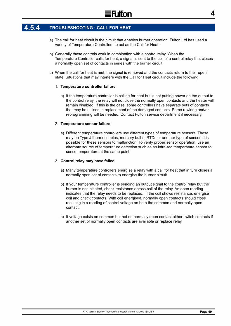
FT-C Vertical Electric Thermal Fluid Heater Manual 12 2013 ISSUE 1 Page 69
4
4.5.4 TROUBLESHOOTING : CALL FOR HEAT
a) The call for heat circuit is the circuit that enables burner operation. Fulton Ltd has used a variety of Temperature Controllers to act as the Call for Heat.
b) Generally these controls work in combination with a control relay. When the Temperature Controller calls for heat, a signal is sent to the coil of a control relay that closes a normally open set of contacts in series with the burner circuit.
c) When the call for heat is met, the signal is removed and the contacts return to their open state. Situations that may interfere with the Call for Heat circuit include the following:
1. Temperature controller failure
a) If the temperature controller is calling for heat but is not putting power on the output to the control relay, the relay will not close the normally open contacts and the heater will remain disabled. If this is the case, some controllers have separate sets of contacts that may be utilised in replacement of the damaged contacts. Some rewiring and/or reprogramming will be needed. Contact Fulton service department if necessary.
2. Temperature sensor failure
a) Different temperature controllers use different types of temperature sensors. These may be Type J thermocouples, mercury bulbs, RTDs or another type of sensor. It is possible for these sensors to malfunction. To verify proper sensor operation, use an alternate source of temperature detection such as an infra-red temperature sensor to sense temperature at the same point.
3. Control relay may have failed
a) Many temperature controllers energise a relay with a call for heat that in turn closes a normally open set of contacts to energise the burner circuit.
b) If your temperature controller is sending an output signal to the control relay but the burner is not initiated, check resistance across coil of the relay. An open reading indicates that the relay needs to be replaced. If the coil shows resistance, energise coil and check contacts. With coil energised, normally open contacts should close resulting in a reading of control voltage on both the common and normally open contact.
c) If voltage exists on common but not on normally open contact either switch contacts if another set of normally open contacts are available or replace relay.
FT-C Vertical Electric Thermal Fluid Heater Manual 12 2013 ISSUE 1Page 70
4
4.5.5 TROUBLESHOOTING : SAFETY INTERLOCK
a) High temperature limit
1. All thermal fluid heaters have at least one High Temperature Limit. The high temperature limit(s) is/are normally closed switch(es) that break on a temperature rise over the set point.
2. The switch may be either a solid state controller or a bulb and capillary type switch. The High Temperature Limit is a safety device that protects the thermal fluid and heat transfer coil from excessively high temperatures.
3. Solid-state high temperature limits will have a manual reset. Bulb and capillary type limits will not have a manual reset. If this/these switch(es) trips, it is generally one of the following issues.
b) Flow rate is too low
1. Too low of a flow rate will result in a higher rate of heat transfer to the thermal fluid and heat transfer coils. This will result in a higher temperature difference between inlet temperature and outlet temperature.
2. It is important to make sure that the minimum flow rate as specified by Fulton for that specific model is maintained.
3. Check inlet and outlet pressures of the heater to determine differential pressure and flow rate. Ensure that this flow rate meets or exceeds minimums specified by Fulton (see chart). Also check differential pressure switch for proper operation and setting.
4.6 MAINTENANCE LOG
Complete the log on the following page, at least once per day as a minimum. It is recommended that the log sheet be filled out twice per shift of operation.
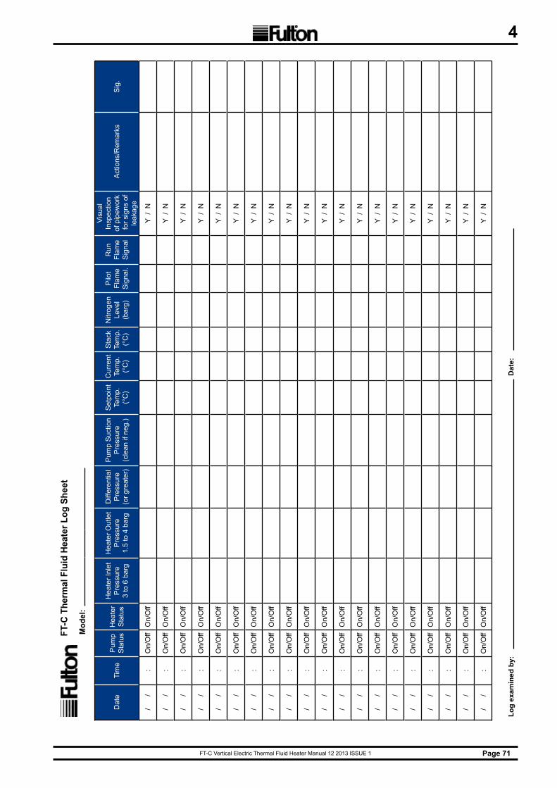
FT-C Vertical Electric Thermal Fluid Heater Manual 12 2013 ISSUE 1 Page 71
4FT
-C T
herm
al F
luid
Hea
ter L
og S
heet
Mod
el:
Dat
eTi
me
Pum
p S
tatu
sH
eate
r S
tatu
s
Hea
ter I
nlet
P
ress
ure
3 to
6 b
arg
Hea
ter O
utle
t P
ress
ure
1.5
to 4
bar
g
Diff
eren
tial
Pre
ssur
e(o
r gre
ater
)
Pum
p S
uctio
n P
ress
ure
(cle
an if
neg
.)
Set
poin
t Te
mp.
(°
C)
Cur
rent
Te
mp.
(°
C)
Sta
ck
Tem
p.
(°C
)
Nitr
ogen
Le
vel
(bar
g)
Pilo
t Fl
ame
Sig
nal.
Run
Fl
ame
Sig
nal
Visu
al
Insp
ectio
nof
pip
ewor
k fo
r sig
ns o
f le
akag
e
Act
ions
/Rem
arks
Sig
.
/
/
:
On/
Off
On/
Off
Y /
N
/
/
:
On/
Off
On/
Off
Y /
N
/
/
:
On/
Off
On/
Off
Y /
N
/
/
:
On/
Off
On/
Off
Y /
N
/
/
:
On/
Off
On/
Off
Y /
N
/
/
:
On/
Off
On/
Off
Y /
N
/
/
:
On/
Off
On/
Off
Y /
N
/
/
:
On/
Off
On/
Off
Y /
N
/
/
:
On/
Off
On/
Off
Y /
N
/
/
:
On/
Off
On/
Off
Y /
N
/
/
:
On/
Off
On/
Off
Y /
N
/
/
:
On/
Off
On/
Off
Y /
N
/
/
:
On/
Off
On/
Off
Y /
N
/
/
:
On/
Off
On/
Off
Y /
N
/
/
:
On/
Off
On/
Off
Y /
N
/
/
:
On/
Off
On/
Off
Y /
N
/
/
:
On/
Off
On/
Off
Y /
N
/
/
:
On/
Off
On/
Off
Y /
N
/
/
:
On/
Off
On/
Off
Y /
N
/
/
:
On/
Off
On/
Off
Y /
N
Log
exam
ined
by:
Dat
e:
FT-C Vertical Electric Thermal Fluid Heater Manual 12 2013 ISSUE 1Page 72
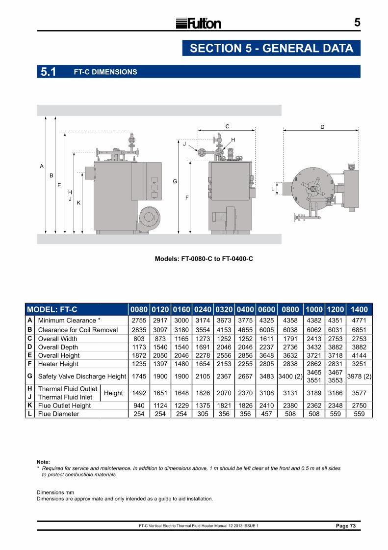
FT-C Vertical Electric Thermal Fluid Heater Manual 12 2013 ISSUE 1 Page 73
5
5.1 FT-C DIMENSIONS
SECTION 5 - GENERAL DATA
Note: * Required for service and maintenance. In addition to dimensions above, 1 m should be left clear at the front and 0.5 m at all sides to protect combustible materials.
MODEL: FT-C 0080 0120 0160 0240 0320 0400 0600 0800 1000 1200 1400A Minimum Clearance * 2755 2917 3000 3174 3673 3775 4325 4358 4382 4351 4771B Clearance for Coil Removal 2835 3097 3180 3554 4153 4655 6005 6038 6062 6031 6851C Overall Width 803 873 1165 1273 1252 1252 1611 1791 2413 2753 2753D Overall Depth 1173 1540 1540 1691 2046 2046 2237 2736 3432 3882 3882E Overall Height 1872 2050 2046 2278 2556 2856 3648 3632 3721 3718 4144F Heater Height 1235 1397 1480 1654 2153 2255 2805 2838 2862 2831 3251
G Safety Valve Discharge Height 1745 1900 1900 2105 2367 2667 3483 3400 (2) 34653551
34673553 3978 (2)
H Thermal Fluid Outlet Height 1492 1651 1648 1826 2070 2370 3108 3131 3189 3186 3577J Thermal Fluid InletK Flue Outlet Height 940 1124 1229 1375 1821 1826 2410 2380 2362 2348 2750L Flue Diameter 254 254 254 305 356 356 457 508 508 559 559
Dimensions mmDimensions are approximate and only intended as a guide to aid installation.
B
K
HJ
C D
E
F
G
HJ
L
A
Models: FT-0080-C to FT-0400-C
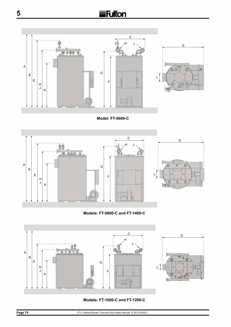
FT-C Vertical Electric Thermal Fluid Heater Manual 12 2013 ISSUE 1Page 74
5
B
K
HJ
E
C
F
G
H J D
L
A
Model: FT-0600-C
A
K
HJ
E
C
F
G
H JD
LB
Models: FT-0800-C and FT-1400-C
B
K
HJ
E
C
F
G
HJ
D
L
A
Models: FT-1000-C and FT-1200-C
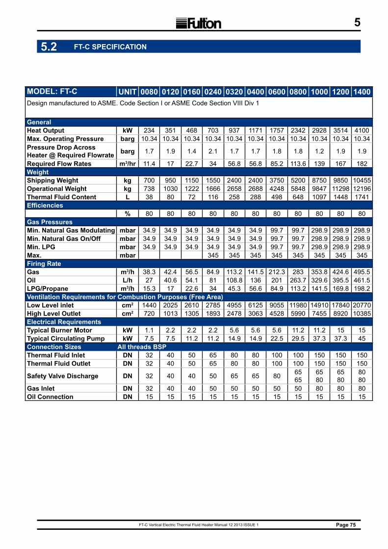
FT-C Vertical Electric Thermal Fluid Heater Manual 12 2013 ISSUE 1 Page 75
5
MODEL: FT-C UNIT 0080 0120 0160 0240 0320 0400 0600 0800 1000 1200 1400Design manufactured to ASME. Code Section I or ASME Code Section VIII Div 1
GeneralHeat Output kW 234 351 468 703 937 1171 1757 2342 2928 3514 4100Max. Operating Pressure barg 10.34 10.34 10.34 10.34 10.34 10.34 10.34 10.34 10.34 10.34 10.34Pressure Drop Across Heater @ Required Flowrate barg 1.7 1.9 1.4 2.1 1.7 1.7 1.8 1.8 1.2 1.9 1.9
Required Flow Rates m3/hr 11.4 17 22.7 34 56.8 56.8 85.2 113.6 139 167 182WeightShipping Weight kg 700 950 1150 1550 2400 2400 3750 5200 8750 9850 10455Operational Weight kg 738 1030 1222 1666 2658 2688 4248 5848 9847 11298 12196Thermal Fluid Content L 38 80 72 116 258 288 498 648 1097 1448 1741Efficiencies
% 80 80 80 80 80 80 80 80 80 80 80Gas PressuresMin. Natural Gas Modulating mbar 34.9 34.9 34.9 34.9 34.9 34.9 99.7 99.7 298.9 298.9 298.9Min. Natural Gas On/Off mbar 34.9 34.9 34.9 34.9 34.9 34.9 99.7 99.7 298.9 298.9 298.9Min. LPG mbar 34.9 34.9 34.9 34.9 34.9 34.9 99.7 99.7 298.9 298.9 298.9Max. mbar 345 345 345 345 345 345 345 345Firing RateGas m3/h 38.3 42.4 56.5 84.9 113.2 141.5 212.3 283 353.8 424.6 495.5Oil L/h 27 40.6 54.1 81 108.8 136 201 263.7 329.6 395.5 461.5LPG/Propane m3/h 15.3 17 22.6 34 45.3 56.6 84.9 113.2 141.5 169.8 198.2Ventilation Requirements for Combustion Purposes (Free Area)Low Level inlet cm2 1440 2025 2610 2785 4955 6125 9055 11980 14910 17840 20770High Level Outlet cm2 720 1013 1305 1893 2478 3063 4528 5990 7455 8920 10385Electrical RequirementsTypical Burner Motor kW 1.1 2.2 2.2 2.2 5.6 5.6 5.6 11.2 11.2 15 15Typical Circulating Pump kW 7.5 7.5 11.2 11.2 14.9 14.9 22.5 29.5 37.3 37.3 45Connection Sizes All threads BSP Thermal Fluid Inlet DN 32 40 50 65 80 80 100 100 150 150 150Thermal Fluid Outlet DN 32 40 50 65 80 80 100 100 150 150 150
Safety Valve Discharge DN 32 40 40 50 65 65 80 6565
6580
6580
8080
Gas Inlet DN 32 40 40 50 50 50 50 50 80 80 80Oil Connection DN 15 15 15 15 15 15 15 15 15 15 15
5.2 FT-C SPECIFICATION
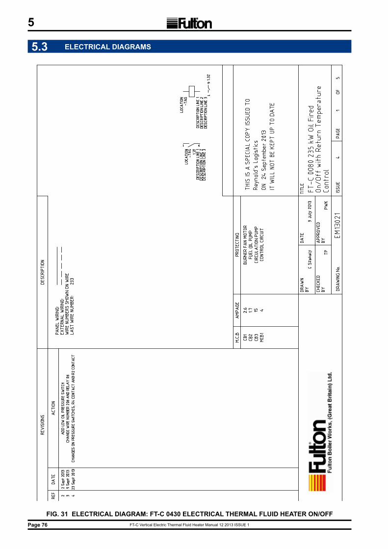
FT-C Vertical Electric Thermal Fluid Heater Manual 12 2013 ISSUE 1Page 76
5
5.3 ELECTRICAL DIAGRAMS
FIG. 31 ELECTRICAL DIAGRAM: FT-C 0430 ELECTRICAL THERMAL FLUID HEATER ON/OFF
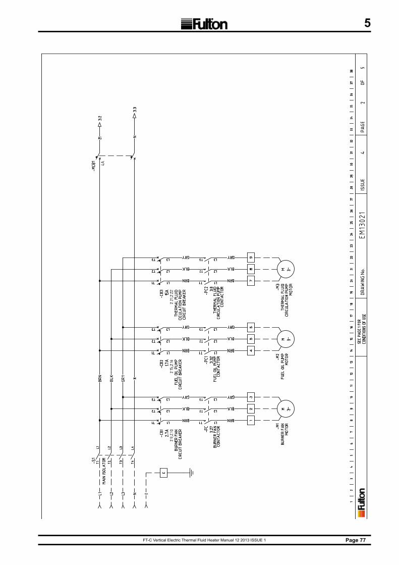
FT-C Vertical Electric Thermal Fluid Heater Manual 12 2013 ISSUE 1 Page 77
5
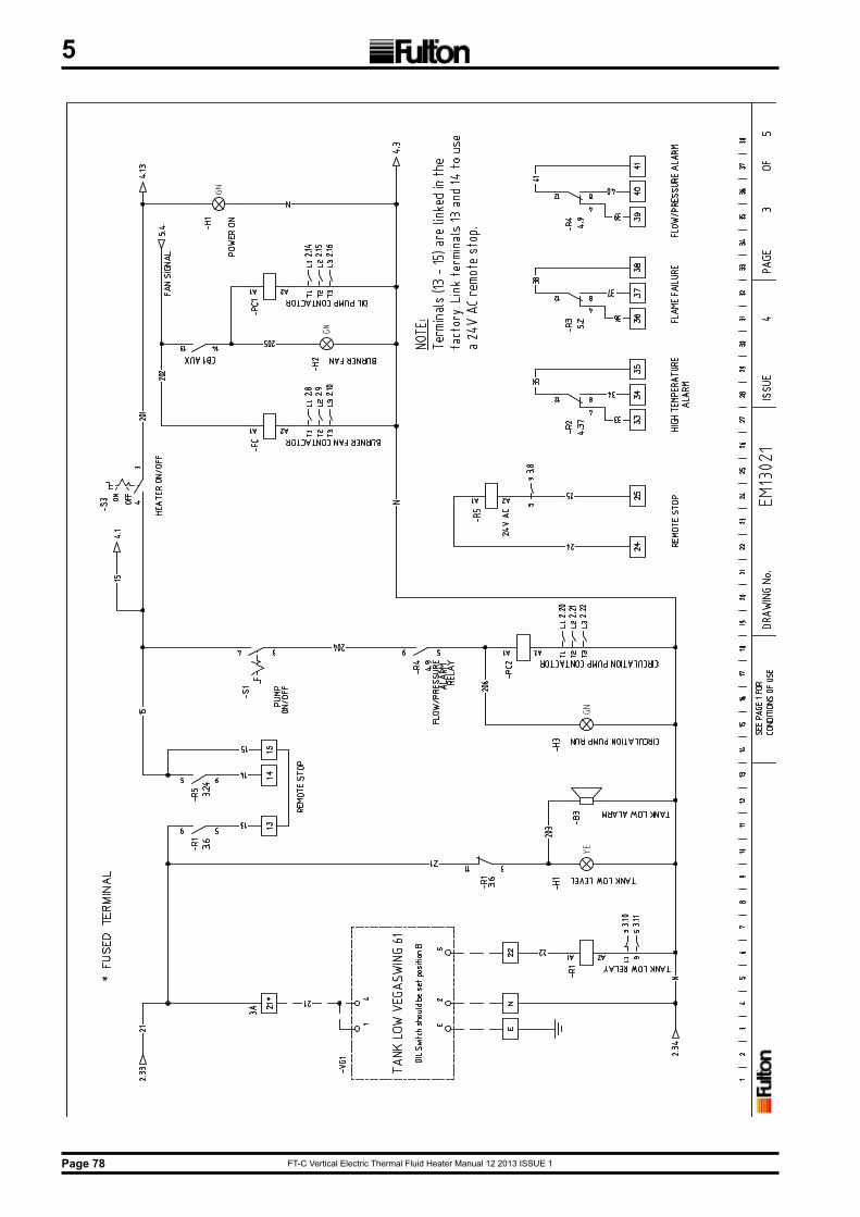
FT-C Vertical Electric Thermal Fluid Heater Manual 12 2013 ISSUE 1Page 78
5
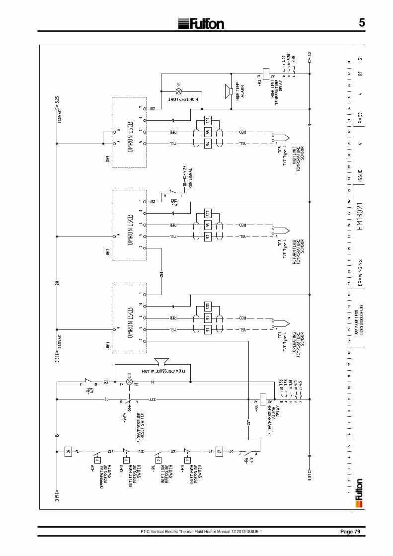
FT-C Vertical Electric Thermal Fluid Heater Manual 12 2013 ISSUE 1 Page 79
5
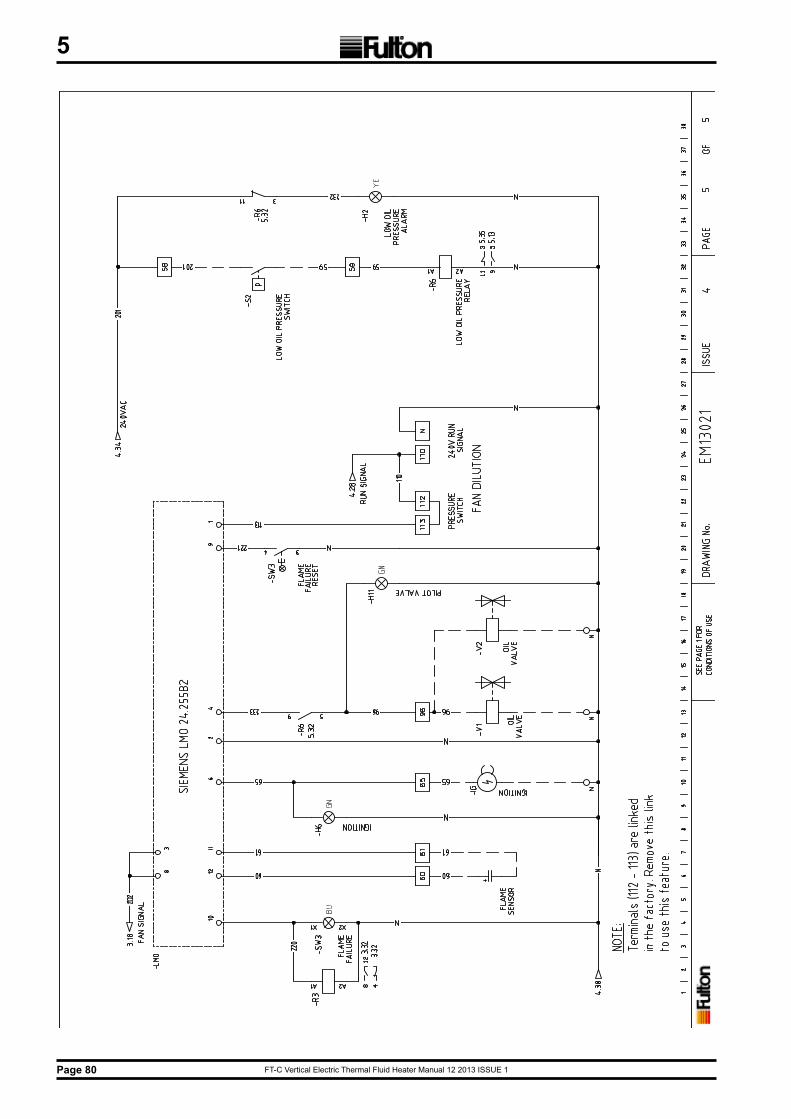
FT-C Vertical Electric Thermal Fluid Heater Manual 12 2013 ISSUE 1Page 80
5
FT-C Vertical Electric Thermal Fluid Heater Manual 12 2013 ISSUE 1 Page 81
6
SECTION 6 - SPARE PARTS
WARNINGThe use of incorrect parts could be a risk to safety
and seriously damage your heater.
!
WARNINGREPLACEMENT SAFETY VALVES
To comply fully with safety regulations it is essential that the correct safety valves are used. The type, size and lift pressure safety valve fitted to a heater is specific to that heater. When ordering spare safety valves it is important that, as well as the information requested above, the following additional information is given:
Heater design pressure (given on the heater data plate).
Make and type (e.g. fig. no.) of safety valve fitted.
If in any doubt contact Fulton Ltd Sales and Service Department for assistance.
!
When ordering replacement or spare parts ensure you provide all the details given in the parts lists together with the following:
Heater number: ________________________________
Heater Model: ________________________________
Commissioning Date: ________________________________

FT-C Vertical Electric Thermal Fluid Heater Manual 12 2013 ISSUE 1
FT-C Vertical Electric Thermal Fluid Heater Manual 12 2013 ISSUE 1
Fulton Ltd
Material & Workmanship Warranty
General Warranty
The Fulton general Guarantee is given in lieu of and in exclusion of any warranty expressed or implied, statutory or otherwise, as to the state, condition, performance, quality or fitness of the goods. Save thereunder we shall be under no obligation or liability of any kind to you in regard to the goods. In the case of new goods manufactured and supplied by us we will make good any defect developing therein under proper use within 12 months of delivery, provided that after investigation in our sole discretion we are satisfied that the defect arose from faulty design, materials or workmanship and from no other cause whatsoever.
Defective goods or parts must be returned to us as soon as possible after discovery of the defect, Costs of carriage and of detaching and incorporating parts will be borne by you. ln all cases at the termination of such 12 months all liability on our part will cease. No liability whatsoever is to be incurred by us in respect of gauge or sight-glasses, packing glands or electric motors or any goods or accessories not of our manufacture. But so far as we are able, we shall let you have the benefit of any guarantee or warranty given to us in respect thereof.
1 Year Warranty
On the Fulton Thermal Fluid Heater
Fulton Ltd will repair or replace EXW Bristol factory any Fulton thermal fluid heater which within one (1)
year of the date of delivery is found to be defective in workmanship, or material,
provided this equipment is operated and maintained by the buyer for the purpose for which it was
designed and in accordance with the Manufacturer’s Handbook. This Warranty does not cover damage
or failures that can be attributed to insufficient maintenance of the thermal fluid.
This Warranty does not include labour or delivery charges of any kind.
FT-C Vertical Electric Thermal Fluid Heater Manual 12 2013 ISSUE 1
Fulton Ltd5 Fernhurst RoadFishpondsBristol BS5 7FGEngland
Telephone: +44 (0) 117 972 3322Fax: +44 (0) 117 972 3358Email: [email protected]
www.fulton.co.uk