installation, operation and programming tracer® uc400 … · the building automation and control...
TRANSCRIPT

Tracer® UC400 Programmable
BACnet® ControllerFor Variable-Air-Volume (VAV) Units
Installation, Operation and Programming
April 2020 VAV-SVX07F-EN
SAFETY WARNINGOnly qualified personnel should install and service the equipment. The installation, starting up, and servicing of heating, ventilating, and air-conditioning equipment can be hazardous and requires specific knowledge and training. Improperly installed, adjusted or altered equipment by an unqualified person could result in death or serious injury. When working on the equipment, observe all precautions in the literature and on the tags, stickers, and labels that are attached to the equipment.
Introduction
The Tracer® UC400 controller is a programmable, general-purpose BACnet®, microprocessor-based, direct digital controller (DDC). This controller can be installed as a factory or field device. When this controller is factory installed on Trane™ variable-air-volume (VAV) terminal units, the factory downloads the unit with the appropriate VAV programs and configuration settings for the unit. These can include sales-order-specified airflow setpoints.
Trane VAV units are made with either pneumatic or microprocessor controls (DDC/VAV). This manual considers only terminal units with BACnet UC400 controller DDC/VAV controls. Factory-installed DDC/VAV controls are available with all single duct terminal units, parallel fan-powered, and series fan-powered units.
The UC400 controller can be configured with three (3) different application programs:
Space Temperature Control (STC)
When the UC400 controller is configured for STC, it modulates the VAV damper blade based on the zone temperature, measured airflow, airflow and temperature, and setpoints, to continuously control conditioned air delivery to the space. The volume of monitored incoming air and the damper adjusts to provide accurate airflow control independent of the duct pressure. The damper modulates discharge airflow into the space between operator airflow setpoints depending on space conditions. Additionally, the fan and heat outputs may be energized depending on the application.
Ventilation Flow Control (VFC)
When the UC400 controller is configured for VFC, it can be applied to a VAV terminal and used to temper cold outdoor air that is brought into a building for ventilation purposes. The tempered air is intended to supply an air handler unit (AHU), which provides comfort control to the zones it is serving. The VAV terminal supplies the correct amount of ventilation air. When reheat is added, it tempers the ventilation air to reduce the load on the air handler by sensing the discharge air temperature of the VAV unit, and controls its long-term average to the discharge air temperature setpoint.
Communicated Discharge Air Temperature Setpoint range is between 19°F and 70°F.
Flow Tracking Control (FTC)
When the UC400 controller is configured for FTC, it works in conjunction with another UC400 configured for STC. The current discharge airflow from the STC controller is communicated to the FTC controller. The FTC controller is then configured to supply a offset (positive or negative) flow relative to the of the other VAV box(es). This is used to provide positive or negative pressure to a contain zone. Warnings, Cautions, and Notices
Safety advisories appear throughout this manual as required. Your personal safety and the proper operation of this machine depend upon the strict observance of these precautions.
Warnings, Cautions, and Notices
Safety advisories appear throughout this manual as required. Your personal safety and the proper operation of this machine depend upon the strict observance of these precautions.
The three types of advisories are defined as follows:
WARNING Indicates a potentially hazardous situation which, if not avoided, could result in death or serious injury.
CAUTIONsIndicates a potentially hazardous situation which, if not avoided, could result in minor or moderate injury. It could also be used to alert against unsafe practices.
NOTICEIndicates a situation that could result in equipment or property-damage only accidents.
©2020 Trane VAV-SVX07F-EN

Introduction
Important Environmental Concerns
Scientific research has shown that certain man-made chemicals can affect the earth’s naturally occurring stratospheric ozone layer when released to the atmosphere. In particular, several of the identified chemicals that may affect the ozone layer are refrigerants that contain Chlorine, Fluorine and Carbon (CFCs) and those containing Hydrogen, Chlorine, Fluorine and Carbon (HCFCs). Not all refrigerants containing these compounds have the same potential impact to the environment. Trane advocates the responsible handling of all refrigerants-including industry replacements for CFCs and HCFCs such as saturated or unsaturated HFCs and HCFCs.
Important Responsible Refrigerant Practices
Trane believes that responsible refrigerant practices are important to the environment, our customers, and the air conditioning industry. All technicians who handle refrigerants must be certified according to local rules. For the USA, the Federal Clean Air Act (Section 608) sets forth the requirements for handling, reclaiming, recovering and recycling of certain refrigerants and the equipment that is used in these service procedures. In addition, some states or municipalities may have additional requirements that must also be adhered to for responsible management of refrigerants. Know the applicable laws and follow them.
WARNING
Proper Field Wiring and Grounding Required!
Failure to follow code could result in death or serious injury. All field wiring MUST be performed by qualified personnel. Improperly installed and grounded field wiring poses FIRE and ELECTROCUTION hazards. To avoid these hazards, you MUST follow requirements for field wiring installation and grounding as described in NEC and your local/state electrical codes. Failure to follow code could result in death or serious injury.
WARNING
Personal Protective Equipment (PPE) Required!
Failure to wear proper PPE for the job being undertaken could result in death or serious injury. Technicians, in order to protect themselves from potential electrical, mechanical, and chemical hazards, MUST follow precautions in this manual and on the tags, stickers, and labels, as well as the instructions below:
• Before installing/servicing this unit, technicians MUST put on all PPE required for the work
being undertaken (Examples; cut resistant gloves/sleeves, butyl gloves, safety glasses, hard
hat/bump cap, fall protection, electrical PPE and arc flash clothing). ALWAYS refer to
appropriate Safety Data Sheets (SDS) and OSHA guidelines for proper PPE.
• When working with or around hazardous chemicals, ALWAYS refer to the appropriate SDS
and OSHA/GHS (Global Harmonized System of Classification and Labeling of Chemicals)
guidelines for information on allowable personal exposure levels, proper respiratory
protection and handling instructions.
• If there is a risk of energized electrical contact, arc, or flash, technicians MUST put on all PPE
in accordance with OSHA, NFPA 70E, or other country-specific requirements for arc flash
protection, PRIOR to servicing the unit. NEVER PERFORM ANY SWITCHING,
DISCONNECTING, OR VOLTAGE TESTING WITHOUT PROPER ELECTRICAL PPE AND ARC
FLASH CLOTHING. ENSURE ELECTRICAL METERS AND EQUIPMENT ARE PROPERLY RATED
FOR INTENDED VOLTAGE.
VAV-SVX07F-EN 3
Introduction
WARNING
Follow EHS Policies!
Failure to follow instructions below could result in death or serious injury.
• All Trane personnel must follow the company’s Environmental, Health and Safety (EHS)
policies when performing work such as hot work, electrical, fall protection, lockout/tagout,
refrigerant handling, etc. Where local regulations are more stringent than these policies,
those regulations supersede these policies.
• Non-Trane personnel should always follow local regulations.
Copyright
This document and the information in it are the property of Trane, and may not be used or reproduced in whole or in part without written permission. Trane reserves the right to revise this publication at any time, and to make changes to its content without obligation to notify any person of such revision or change.
Trademarks
All trademarks referenced in this document are the trademarks of their respective owners.
Revision History
Removed original Declaration of Conformance page with the statement listed above for European
compliance.
4 VAV-SVX07F-EN

Table of Contents
BACnet® Protocol . . . . . . . . . . . . . . . . . . . . . . . . . . . . . . . . . . . . . . . . . . . . . . . . . 7
BACnet Testing Laboratory (BTL) Certification . . . . . . . . . . . . . . . . . . . . . . . . 7
Shipping and Storage . . . . . . . . . . . . . . . . . . . . . . . . . . . . . . . . . . . . . . . . . . . . . . 9
UC400 Controller Features . . . . . . . . . . . . . . . . . . . . . . . . . . . . . . . . . . . . . . . . . . 9
Controller Comparisons . . . . . . . . . . . . . . . . . . . . . . . . . . . . . . . . . . . . . . . . . . . 10
Device Connections . . . . . . . . . . . . . . . . . . . . . . . . . . . . . . . . . . . . . . . . . . . . . . . 11
Device Inputs/Outputs . . . . . . . . . . . . . . . . . . . . . . . . . . . . . . . . . . . . . . . . . . . . . 12
Analog Inputs . . . . . . . . . . . . . . . . . . . . . . . . . . . . . . . . . . . . . . . . . . . . . . . . . 12
Universal Inputs . . . . . . . . . . . . . . . . . . . . . . . . . . . . . . . . . . . . . . . . . . . . . . . 12
Pressure Inputs . . . . . . . . . . . . . . . . . . . . . . . . . . . . . . . . . . . . . . . . . . . . . . . . 12
Binary Inputs . . . . . . . . . . . . . . . . . . . . . . . . . . . . . . . . . . . . . . . . . . . . . . . . . . 13
Binary Outputs . . . . . . . . . . . . . . . . . . . . . . . . . . . . . . . . . . . . . . . . . . . . . . . . . 13
Analog Outputs . . . . . . . . . . . . . . . . . . . . . . . . . . . . . . . . . . . . . . . . . . . . . . . . 13
Wiring Installation . . . . . . . . . . . . . . . . . . . . . . . . . . . . . . . . . . . . . . . . . . . . . . . . 14
UC400 Controller Pre-power Check-out . . . . . . . . . . . . . . . . . . . . . . . . . . . . 14Transformer Recommendations . . . . . . . . . . . . . . . . . . . . . . . . . . . . . . . . 14Guidelines . . . . . . . . . . . . . . . . . . . . . . . . . . . . . . . . . . . . . . . . . . . . . . . . . . 15Wiring Guidelines . . . . . . . . . . . . . . . . . . . . . . . . . . . . . . . . . . . . . . . . . . . . 17Wiring Best Practices . . . . . . . . . . . . . . . . . . . . . . . . . . . . . . . . . . . . . . . . . 18Setting Up the UC400 Controller on a BACnet Link . . . . . . . . . . . . . . . . . 19Setting the Address . . . . . . . . . . . . . . . . . . . . . . . . . . . . . . . . . . . . . . . . . . . 19BACnet Networks With a Tracer SC System Controller . . . . . . . . . . . . . . 20Wiring Requirements . . . . . . . . . . . . . . . . . . . . . . . . . . . . . . . . . . . . . . . . . 21Connecting the Wires . . . . . . . . . . . . . . . . . . . . . . . . . . . . . . . . . . . . . . . . . 21Power On Check . . . . . . . . . . . . . . . . . . . . . . . . . . . . . . . . . . . . . . . . . . . . . 22
Application Wiring . . . . . . . . . . . . . . . . . . . . . . . . . . . . . . . . . . . . . . . . . . . . . 22Zone Sensor Wiring . . . . . . . . . . . . . . . . . . . . . . . . . . . . . . . . . . . . . . . . . . 22Duct Temperature Sensor Wiring . . . . . . . . . . . . . . . . . . . . . . . . . . . . . . . 24Binary Wiring . . . . . . . . . . . . . . . . . . . . . . . . . . . . . . . . . . . . . . . . . . . . . . . . 24
UC400 Controller Points and Parameters . . . . . . . . . . . . . . . . . . . . . . . . . . . . . 28
Status Utility . . . . . . . . . . . . . . . . . . . . . . . . . . . . . . . . . . . . . . . . . . . . . . . . . . 28Unit Summary Screen . . . . . . . . . . . . . . . . . . . . . . . . . . . . . . . . . . . . . . . . . 28Analog, Binary, and Multi-state Screens . . . . . . . . . . . . . . . . . . . . . . . . . . 29
Equipment Settings . . . . . . . . . . . . . . . . . . . . . . . . . . . . . . . . . . . . . . . . . . . . . 30Setpoints Screen . . . . . . . . . . . . . . . . . . . . . . . . . . . . . . . . . . . . . . . . . . . . . 30Commissioning Screen . . . . . . . . . . . . . . . . . . . . . . . . . . . . . . . . . . . . . . . . 33Configuration Screen . . . . . . . . . . . . . . . . . . . . . . . . . . . . . . . . . . . . . . . . . 34
Calibration . . . . . . . . . . . . . . . . . . . . . . . . . . . . . . . . . . . . . . . . . . . . . . . . . . . . 36
VAV-SVX07F-EN 5

Table of Contents
Occupancy Modes . . . . . . . . . . . . . . . . . . . . . . . . . . . . . . . . . . . . . . . . . . . . . . 36Occupied Mode . . . . . . . . . . . . . . . . . . . . . . . . . . . . . . . . . . . . . . . . . . . . . . 36Unoccupied Mode . . . . . . . . . . . . . . . . . . . . . . . . . . . . . . . . . . . . . . . . . . . . 37Occupied Standby Mode . . . . . . . . . . . . . . . . . . . . . . . . . . . . . . . . . . . . . . 37Occupied Bypass Mode . . . . . . . . . . . . . . . . . . . . . . . . . . . . . . . . . . . . . . . 37
Space Temperature Control (STC) for Single Duct and Fan-powered Units 38Single Duct Units . . . . . . . . . . . . . . . . . . . . . . . . . . . . . . . . . . . . . . . . . . . . . 38Fan-Powered Units . . . . . . . . . . . . . . . . . . . . . . . . . . . . . . . . . . . . . . . . . . . 43Ventilation Flow Control (VFC) . . . . . . . . . . . . . . . . . . . . . . . . . . . . . . . . . . 45Flow Tracking (FTC) . . . . . . . . . . . . . . . . . . . . . . . . . . . . . . . . . . . . . . . . . . . 48
Diagnostics . . . . . . . . . . . . . . . . . . . . . . . . . . . . . . . . . . . . . . . . . . . . . . . . . . . 50
Troubleshooting Procedures . . . . . . . . . . . . . . . . . . . . . . . . . . . . . . . . . . . . . 51UC400 Controller Failure . . . . . . . . . . . . . . . . . . . . . . . . . . . . . . . . . . . . . . 51Wired Zone Sensor Failure . . . . . . . . . . . . . . . . . . . . . . . . . . . . . . . . . . . . . 53Supply/Discharge Air Temperature Sensor Failure . . . . . . . . . . . . . . . . . 58CO2 Sensor Failure . . . . . . . . . . . . . . . . . . . . . . . . . . . . . . . . . . . . . . . . . . . 59VAV Series Fan Failure . . . . . . . . . . . . . . . . . . . . . . . . . . . . . . . . . . . . . . . . 61VAV Parallel Fan Failure . . . . . . . . . . . . . . . . . . . . . . . . . . . . . . . . . . . . . . . 62PSC (Permanent Split Capacitor) Variable Speed Motor Check . . . . . . . 63VAV Electric Heat Stage Failure . . . . . . . . . . . . . . . . . . . . . . . . . . . . . . . . . 64VAV Modulating Hot Water Failure . . . . . . . . . . . . . . . . . . . . . . . . . . . . . . 65
6 VAV-SVX07F-EN
BACnet® Protocol
The Building Automation and Control Network (BACnet and ANSI/ASHRAE Standard 135-2004) protocol is a standard that allows building automation systems or components from different manufacturers to share information and control functions. BACnet provides building owners the capability to connect various types of building control systems or subsystems together for many uses. In addition, multiple vendors can use this protocol to share information for monitoring and supervisory control between systems and devices in a multi-vendor interconnected system.
The BACnet protocol identifies standard objects (data points) called BACnet objects. Each object has a defined list of properties that provide information about that object. BACnet also defines a number of standard application services that are used to access data and manipulate these objects and provides a client/server communication between devices.
BACnet Testing Laboratory (BTL) Certification
The UC400 supports the BACnet communication protocol and has been designed to meet the requirements of the application-specific control profile. For more details, refer to the BTL web site at www.bacnetinternational.org.
VAV-SVX07F-EN 7
Specifications and Dimensions
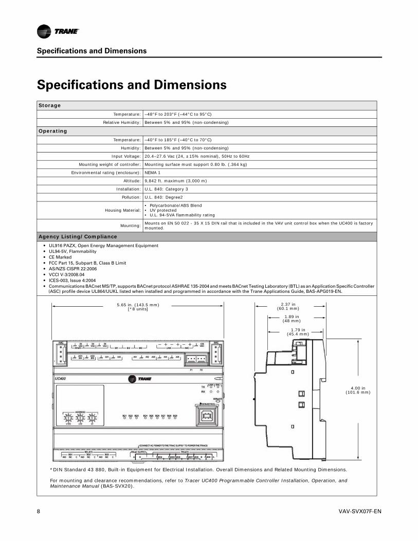
Specifications and Dimensions
StorageTemperature: –48°F to 203°F (–44°C to 95°C)
Relative Humidity: Between 5% and 95% (non-condensing)
OperatingTemperature: –40°F to 185°F (–40°C to 70°C)
Humidity: Between 5% and 95% (non-condensing)
Input Voltage: 20.4–27.6 Vac (24, ±15% nominal), 50Hz to 60Hz
Mounting weight of controller: Mounting surface must support 0.80 lb. (.364 kg)
Environmental rating (enclosure): NEMA 1
Altitude: 9,842 ft. maximum (3,000 m)
Installation: U.L. 840: Category 3
Pollution: U.L. 840: Degree2
Housing Material:• Polycarbonate/ABS Blend• UV protected• U.L. 94-5VA flammability rating
Mounting: Mounts on EN 50 022 - 35 X 15 DIN rail that is included in the VAV unit control box when the UC400 is factory mounted.
Agency Listing/Compliance• UL916 PAZX, Open Energy Management Equipment• UL94-5V, Flammability• CE Marked• FCC Part 15, Subpart B, Class B Limit• AS/NZS CISPR 22:2006• VCCI V-3/2008.04• ICES-003, Issue 4:2004• Communications BACnet MS/TP, supports BACnet protocol ASHRAE 135-2004 and meets BACnet Testing Laboratory (BTL) as an Application Specific Controller
(ASC) profile device UL864/UUKL listed when installed and programmed in accordance with the Trane Applications Guide, BAS-APG019-EN.
*DIN Standard 43 880, Built-in Equipment for Electrical Installation. Overall Dimensions and Related Mounting Dimensions.
For mounting and clearance recommendations, refer to Tracer UC400 Programmable Controller Installation, Operation, and Maintenance Manual (BAS-SVX20).
5.65 in. (143.5 mm)[*8 units]
2.37 in(60.1 mm)
1.89 in(48 mm)
1.79 in(45.4 mm)
4.00 in(101.6 mm)
8 VAV-SVX07F-EN

Shipping and Storage
Each VAV order ships with service literature. When unpacking, ensure that the literature is not lost or discarded with the packing material.
Important:� Visually inspect the individual components for obvious defects or damage. All components are thoroughly inspected before leaving the factory. Any claims for damage incurred during shipment must be filed with the carrier.
If storing any component of the VAV system and/or field installed accessories for a period of time prior to installation, those components must be protected from the elements. Refer to “Specifications and Dimensions,” p. 8 for storage location temperature and the relative humidity ranges.
Important:� The warranty will not cover damage to the VAV or controls due to negligence during storage. A controlled indoor environment must be used for storage.
UC400 Controller Features
Table 1 provides information about the features of the UC400 controller.
Table 1. UC400 Features
Feature Description
Controller Interface Flexibility:The UC400 controller allows VAV units to communicate on a BACnet MS/TP link and is compatible with the latest generation of Trane controls. This controller can operate in standalone mode, peer-to-peer with one or more other units, or when connected to a Tracer SC or a 3rd party building automation system that supports BACnet.
Flow Tracking: The UC400 controller is designed with the ability to be applied in flow tracking applications. This allows the controller to be paired with one of its peers to mirror the flow of the lead unit, with or without an offset (positive or negative static pressure as desired).
Ventilation Flow Control with Tempering:
The UC400 controller is designed with the ability to be applied in ventilation flow control applications. These applications combine a fresh air unit with ventilation boxes to provide fresh (tempered) air to a zone. This feature also includes a freeze protection sequence to protect the hot water reheat coil from low supply air temperatures.
Auto-commissioning Sequence:
The UC400 controller is designed with an auto-commissioning sequence. With a discharge air temperature sensor, this feature exercises the air valve, fan, and heat in the box and records the temperature before/after the action. This allows the installer to easily verify the operation of the unit and commission by exception. An auto-commissioning report can be generated with Tracer TU service tool.
Automatic Calibration:The UC400 controller is designed to automatically calibrate the flow transducer each time the unit transitions to unoccupied. This eliminates the need to initiate/schedule calibration for most installations. The exception is 24/7 sites, in which case, Tracer SC can be used to initiate/schedule calibration.
Temporary Heat (Construction Mode):
Upon reset (and power-up), if the controller does not detect a valid space temperature, the controller will provide temporary heat by driving the air valve to the heating maximum position.Note: The unit will provide heat only if the air handler unit provides hot air.
Local Versus Remote Reheat Flexibility:
The controller can be configured to have local and/or remote heat. In addition, provided configuration flexibility allows the installer to select priority for either local or remote heat has.
Spare Inputs/Outputs:The UC400 controller has spare I/Os that are not used by the VAV applications. These spare I/Os can be programmed using the Tracer Graphical Programming editor (by means of the Tracer TU service tool) to measure and/or control ancillary devices such exhaust fans, second air valve for dual duct VAV, or sensing relative humidity.
Removable Terminal Connectors:The UC400 controller connectors are 2-part connectors with 5.08 millimeter pin separation. The headers are attached on the Tracer UC400 controller itself. The other portion of the connector is either a screw terminal (for field wiring) or a terminal housing (for factory wiring). Spare screw terminals come factory installed for field mounted wired zone sensors and common accessories.
Wireless Zone Sensors:The UC400 controller is compatible with the latest wireless zone sensors available from Trane. Wireless zone sensors provide flexibility of sensor location and re-location as well as reducing the cost of installation. Wireless zone sensor receivers are available as a factory or field installed option.
Firmware (Application Code) Download:
The UC400 controller has been designed with flash memory. This allows the option of upgrading the application code in the field without changing out the controller.
Drive Min/Max from Zone Sensor:
When applied with a Trane zone sensor module, that includes a thumbwheel setpoint or a LCD display, the UC400 controller can easily be overridden to minimum and maximum flow. By simply turning the thumbwheel to * or increasing the setpoint to maximum on display sensors (end of range in one direction), the controller drives the air valve to the minimum flow setpoint. Likewise, turning the thumbwheel to the ** or decreasing the setpoint to minimum on display sensors (end of range in the other direction) the controller drives the air valve to the maximum flow setpoint. This feature can be disabled by putting Airflow Override Local, Multistate Input 2, and Out of Service using Tracer TU.
Auto-commissioning Report (Tracer SC and Tracer TU):
Tracer SC and Tracer TU both include auto-commissioning reports that extracts and formats the commissioning data for each VAV controller. This commissioning report is valuable both for the installer and for the owner. The feature enables the system to be commissioned by exception, providing a benefit for the installer. The feature also can be used as validation that provides value to the owner.
VAV-SVX07F-EN 9
Controller Comparisons
Controller Comparisons
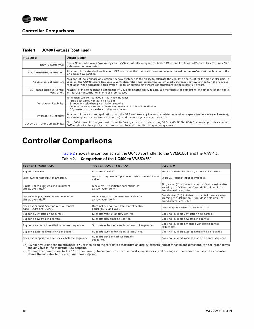
Table 2 shows the comparison of the UC400 controller to the VV550/551 and the VAV 4.2.Table 2.
Tracer UC400 VAV Tracer VV550/VV551 VAV 4.2Supports BACnet. Supports LonTalk. Supports Trane proprietary Comm4 or Comm3.
Local CO2 sensor input is available. No local CO2 sensor input. Uses only a communicated value. Local CO2 sensor input is available.
Single star (*) initiates cool minimumairflow override.(a)
(a) By simply turning the thumbwheel to *, or increasing the setpoint to maximum on display sensors (end of range in one direction), the controller drives the air valve to the minimum flow setpoint.
Single star (*) initiates cool minimumairflow override.(a)
Single star (*) initiates maximum flow override after pressing the ON button. Override is held until the thumbwheel is adjusted.
Double star (**) initiates cool maximumairflow override.(b)
(b) Turning the thumbwheel to the **, or decreasing the setpoint to minimum on display sensors (end of range in the other direction), the controller drives the air valve to the maximum flow setpoint.
Double star (**) initiates cool maximumairflow override.(b)
Double star (**) initiates unoccupied override after pressing the ON button. Override is held until the thumbwheel is adjusted.
Does not support VariTrac central controlpanel (CCP2 and CCP3).
Does not support VariTrac central controlpanel (CCP2 and CCP3). Does support VariTrac CCP2 and CCP3.
Supports ventilation flow control. Supports ventilation flow control. Does not support ventilation flow control.
Supports flow tracking control. Supports flow tracking control. Does not support flow tracking control.
Supports enhanced ventilation control sequences. Supports enhanced ventilation control sequences. Does not support enhanced ventilation control sequences.
Supports auto-commissioning sequence. Supports auto-commissioning sequence. Does not support auto-commissioning sequence.
Does not support zone sensor air balance sequence. Supports zone sensor air balancesequence. Does not support zone sensor air balance sequence.
Comparison of the UC400 to VV550/551
Easy to Setup VAS: Tracer SC includes a new VAV Air System (VAS) specifically designed for both BACnet and LonTalk® VAV controllers. This new VAS is designed for easy setup.
Static Pressure Optimization: As a part of the standard application, VAS calculates the duct static pressure setpoint based on the VAV unit with a damper in the maximum flow position.
Ventilation Optimization:As a part of the standard application, the VAV system has the ability to calculate the ventilation setpoint for the air handler unit. In addition, the UC400 controllers have a ventilation ratio limit feature that automatically increases airflow to maintain the required ventilation while operating within system limits for outside air percent concentrations in the supply air stream.
CO2-based Demand Control Ventilation:
As a part of the standard application, the VAV system has the ability to calculate the ventilation setpoint for the air handler unit based on the CO2 concentration in one or more spaces.
Ventilation Flexibility:
Ventilation can be managed in the following ways:• Fixed occupancy ventilation setpoint• Scheduled (calculated) ventilation setpoint• Occupancy sensor to switch between normal and reduced ventilation• CO2 sensor for demand-controlled ventilation
Temperature Statistics: As a part of the standard application, both the VAS and Area applications calculate the minimum space temperature (and source), maximum space temperature (and source), and the average space temperature.
UC400 Controller Compatibility: The UC400 controller integrates with other BACnet systems and devices using BACnet MS/TP. The UC400 controller provides standard BACnet objects (data points) that can be read by and/or written to by other systems.
Table 1. UC400 Features (continued)
Feature Description
10 VAV-SVX07F-EN
Device Connections
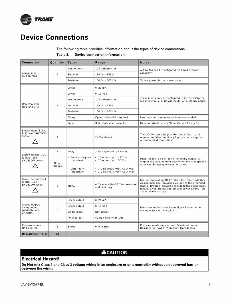
The following table provides information about the types of device connections.
Table 3.
Connection Quantity Types Range Notes
Analog input(AI1 to AI5) 5
Temperature 10 kthermistor AI1 to AI4 can be configured for timed override capability.Setpoint 189 to 889
Resistive 100 to 100 k Typically used for fan speed switch.
Universal input(UI1 and UI2) 2
Linear 0–20 mA
These inputs may be configured to be thermistor or resistive inputs, 0–10 Vdc inputs, or 0–20 mA inputs.
Linear 0–10 Vdc
Temperature 10 kthermistor
Setpoint 189 to 889
Resistive 100 to 100 k
Binary Open collector/dry contact Low impedance relay contacts recommended.
Pulse Solid state open collector Minimum dwell time is 25 ms On and 25 ms Off.
Binary input (BI1 to BI3) See CAUTION below.
!3 24 Vac detect
The UC400 controller provides the 24 Vac that is required to drive the binary inputs when using the recommended connections.
Binary output (BO1 to BO3) See CAUTION below.
!
3 Relay 2.88 A @24 Vac pilot duty
Power needs to be wired to the binary output. All outputs are isolated from each other and from ground or power. Ranges given are per contact.Other
Ranges
• General purpose (resistive)
• Motor duty (inductive)
• 10 A max up to 277 Vac• 10 A max up to 30 Vdc
• 1/3 hp @125 Vac (7.5 A max)• 1/2 hp @277 Vac (7.5 A max)
Binary output (BO4 to BO9) See CAUTION below.
!6 TRIAC 0.5 A max @24-277 Vac, resistive
and pilot duty
Use for modulating TRIAC. User determines whether closing high side (providing voltage to the grounded load) or low side (providing ground to the power load). Ranges given are per contact and power comes from TRIAC SUPPLY circuit.
Analog output/binary input(AO1/BI4 and AO2/BI5)
2
Linear output 0–20 mA
Each termination must be configured as either an analog output or binary input.
Linear output 0–10 Vdc
Binary input Dry contact
PWM output 80 Hz signal @ 15 Vdc
Pressure inputs(PI1 and PI2) 2 3-wire 0–5 in H2O
Pressure inputs supplied with 5 volts of power. Designed for Kavlico™ pressure transducers.
Overall Point Total 23
Device connection information
CAUTION
Electrical Hazard!
Do Not mix Class 1 and Class 2 voltage wiring in an enclosure or on a controller without an approved barrier between the wiring.
VAV-SVX07F-EN 11
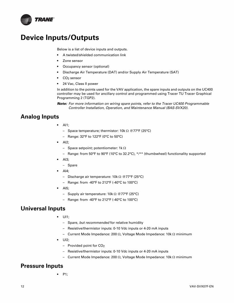
Device Inputs/Outputs
Below is a list of device inputs and outputs.
• A twisted/shielded communication link
• Zone sensor
• Occupancy sensor (optional)
• Discharge Air Temperature (DAT) and/or Supply Air Temperature (SAT)
• CO2 sensor
• 24 Vac, Class II power
In addition to the points used for the VAV application, the spare inputs and outputs on the UC400 controller may be used for ancillary control and programmed using Tracer TU Tracer Graphical Programming 2 (TGP2).
Note: For more information on wiring spare points, refer to the Tracer UC400 Programmable Controller Installation, Operation, and Maintenance Manual (BAS-SVX20).
Analog Inputs
• AI1;
– Space temperature; thermistor: 10k @77°F (25°C)
– Range: 32°F to 122°F (0°C to 50°C)
• AI2;
– Space setpoint; potentiometer: 1k
– Range: from 50°F to 90°F (10°C to 32.2°C), */** (thumbwheel) functionality supported
• AI3;
– Spare
• AI4;
– Discharge air temperature: 10k @77°F (25°C)
– Range: from -40°F to 212°F (-40°C to 100°C)
• AI5;
– Supply air temperature: 10k @77°F (25°C)
– Range: from -40°F to 212°F (-40°C to 100°C)
Universal Inputs
• UI1;
– Spare, but recommended for relative humidity
– Resistive/thermistor inputs: 0-10 Vdc inputs or 4-20 mA inputs
– Current Mode Impedance: 200 , Voltage Mode Impedance: 10k minimum
• UI2;
– Provided point for CO2
– Resistive/thermistor inputs: 0-10 Vdc inputs or 4-20 mA inputs
– Current Mode Impedance: 200 , Voltage Mode Impedance: 10k minimum
Pressure Inputs
• P1;
12 VAV-SVX07F-EN

Device Inputs/Outputs
– Supply airflow, pressure transducer
– From 0 to 2 in. water column (0 to 498 Pa)
• P2;
– Spare (recommended for dual duct secondary airflow)
Binary Inputs
• BI1;
– Occupancy
• BI2;
– Spare
• BI3;
– Spare
Binary Outputs
Table 4. Binary output information
Binary Outputs Type Output Rating Pilot dutyBO1 Fan 10A up to 277 Vac 10A at 30 Vac/VDC, 2A at 120 Vac, 8 A at 250 Vac
BO2 Spare Relay 10A up to 277 Vac 10A at 30 Vac/VDC, 2A at 120 Vac, 8 A at 250 Vac
BO3 Spare Relay 10A up to 277 Vac 10A at 30 Vac/VDC, 2A at 120 Vac, 8 A at 250 Vac
BO4 Fan ON/Off 24-27 Vac, 0.5A Resistive VA
BO5 Heat stage 3 TRIAC 24-27 Vac, 0.5A Resistive VA
BO6 Heat stage 2/Water Valve Close TRIAC 24-27 Vac, 0.5A Resistive VA
BO7 Heat stage 1/Water Valve Open TRIAC 24-27 Vac, 0.5A Resistive VA
BO8 Air Damper Close TRIAC 24-27 Vac, 0.5A Resistive VA
BO9 Air Damper Open TRIAC 24-27 Vac, 0.5A Resistive VA
Analog Outputs
• AO1;
– Spare output.
– Voltage output is 0 to 10 Vdc, 500 minimum impedance.
– Current output is 4-20 mA, 500 max. impedance.
– Also can output 100 Hz PWM signal for control of a Trane fan-powered ECM fan setpoint signal to the EC motor.
Note: ECM fan for future production.
• AO2;
– Spare.
– Voltage output is 0 to 10 Vdc, 500 minimum impedance.
– Current output is 4-20 mA, 500 maximum impedance.
– Also used on Trane VAV units for SCR electric heat 0-to-10 Vdc modulation control.
Note: For more information on wiring spare points, refer to the Tracer UC400 Programmable Controller Installation, Operation, and Maintenance Manual (BAS-SVX20).
VAV-SVX07F-EN 13

Wiring Installation
This section provides wiring guideline information about:
• “UC400 Controller Pre-power Check-out”
• “UC400 Controller Power Wiring,” p. 15
• “BACnet MS/TP Communication Link,” p. 17
• “Application Wiring,” p. 22
UC400 Controller Pre-power Check-out
Carefully follow the check-out procedures below and read all warnings and notices.
WARNING
Live Electrical Components!
During installation, testing, servicing and troubleshooting of this product, it may be necessary to work with live electrical components. Have a qualified licensed electrician or other individual who has been properly trained in handling live electrical components perform these tasks. Failure to follow all electrical safety precautions when exposed to live electrical components could result in death or serious injury.
• Check the supply voltage at XFRM.
Note: Proper polarity must be maintained. The 24 Vac is the hot side (+) and is the ground side (-) of the 24 Vac input.
Important:� The UC400 controller cannot be powered from a common 24 Vac transformer that is supplying power to a device containing a full-wave rectifier bridge in its power supply. The acceptable voltage is 20.4 to 27.6 (24 Vac nominal). However, voltages at either extreme may result in increased system instability.
• Verify communications wiring has properly been terminated to link plus and negative at XFRM 24 Vac (+) and (-) terminals.
Note: Polarity must be maintained on the BACnet communications link.
• Verify that the zone sensor connections are correct as detailed in the UC400 controller wiring section.
• If heat has been added to the unit, verify that the proper output connections are correct, as detailed in the UC400 controller wiring section.
• Verify that the tubing is properly connected to the differential pressure transducer.
Transformer Recommendations
A 24 Vac power supply must be used for proper operation of the binary inputs, which requires 24 Vac detection. In addition, the spare 24 Vac outputs may be used to power relays and TRIACS.
• AC transformer requirements: UL listed, Class 2 power transformer, 24 Vac ±15%, device max load 24 VA. The transformer must be sized to provide adequate power to the controller (24 VA) and binary outputs loads.
• CE-compliant installations: The transformer must be CE marked and SELV compliant per IEC standards.
14 VAV-SVX07F-EN

Wiring Installation
UC400 Controller Power Wiring
The following section provides wiring guidelines for powering the UC400 controller.
WARNING
Hazardous Voltage!
Disconnect all electric power, including remote disconnects before servicing. Follow proper lockout/tagout procedures to ensure the power can not be inadvertently energized. Failure to disconnect power before servicing could result in death or serious injury.
WARNING
Electrocution and Fire Hazards with Improperly Installed and Grounded Field Wiring!
Improperly installed/grounded field wiring poses FIRE & ELECTROCUTION hazards. To avoid these hazards, the user MUST follow requirements for field wiring installation and grounding as described in NEC and local/state electrical codes. All field wiring MUST be performed by qualified personnel. Failure to follow these requirements could result in death or serious injury.
NOTICE:
Use Copper Conductors Only!
Unit terminals are not designed to accept other types of conductors. Failure to use copper conductors could result in equipment damage.
Guidelines
• Use 18 AWG copper wire (recommended) for power and connect to terminals XFRM 24 Vac and .
• Use U.L. listed, Class 2 power transformer, 20.4 to 27.6 Vac (24 Vac nominal).
• Size the transformer to provide adequate power to the UC400 controller (24 VA maximum) and outputs (maximum 12 VA for each binary output).
Important:� A dedicated 24 Vac, Class 2 transformer is recommended to power the Tracer UC400 controller. When powering multiple controllers from one transformer, polarity must be maintained. Terminal 24 Vac is designated positive (+) and terminal is negative (-) to the unit casing ground. It is important to include power consumption in the calculations.
• The power consumption for cooling-only Series F Models (VariTrac™ and VariTrane™) is up to 28 VA. Refer to Table 5, p. 16 for information about calculating actual VA requirements.
VAV-SVX07F-EN 15
Wiring Installation
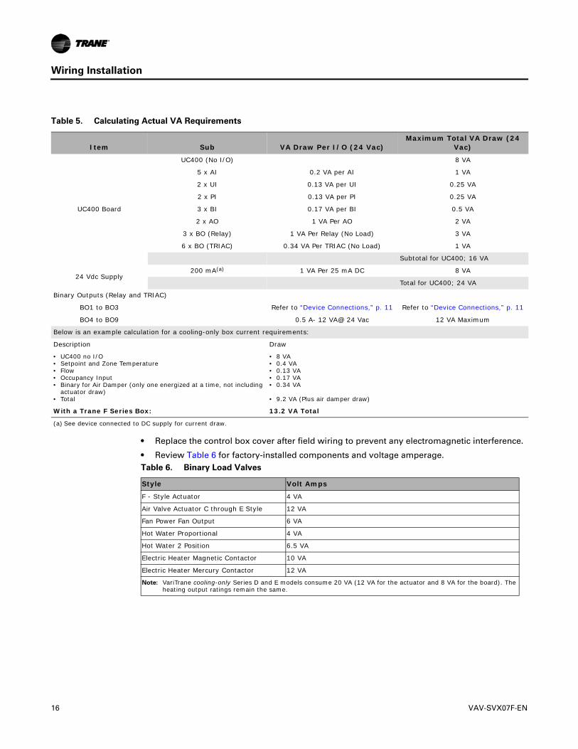
Table 5. Calculating Actual VA Requirements
Item Sub VA Draw Per I/O (24 Vac)Maximum Total VA Draw (24
Vac)
UC400 Board
UC400 (No I/O) 8 VA
5 x AI 0.2 VA per AI 1 VA
2 x UI 0.13 VA per UI 0.25 VA
2 x PI 0.13 VA per PI 0.25 VA
3 x BI 0.17 VA per BI 0.5 VA
2 x AO 1 VA Per AO 2 VA
3 x BO (Relay) 1 VA Per Relay (No Load) 3 VA
6 x BO (TRIAC) 0.34 VA Per TRIAC (No Load) 1 VA
Subtotal for UC400; 16 VA
24 Vdc Supply200 mA(a)
(a) See device connected to DC supply for current draw.
1 VA Per 25 mA DC 8 VA
Total for UC400; 24 VA
Binary Outputs (Relay and TRIAC)
BO1 to BO3 Refer to “Device Connections,” p. 11 Refer to “Device Connections,” p. 11
BO4 to BO9 0.5 A- 12 VA@ 24 Vac 12 VA Maximum
Below is an example calculation for a cooling-only box current requirements:
Description Draw
• UC400 no I/O• Setpoint and Zone Temperature• Flow• Occupancy Input• Binary for Air Damper (only one energized at a time, not including
actuator draw)• Total
• 8 VA• 0.4 VA• 0.13 VA• 0.17 VA• 0.34 VA
• 9.2 VA (Plus air damper draw)
With a Trane F Series Box: 13.2 VA Total
• Replace the control box cover after field wiring to prevent any electromagnetic interference.
• Review Table 6 for factory-installed components and voltage amperage.Table 6.
Style Volt Amps
F - Style Actuator 4 VA
Air Valve Actuator C through E Style 12 VA
Fan Power Fan Output 6 VA
Hot Water Proportional 4 VA
Hot Water 2 Position 6.5 VA
Electric Heater Magnetic Contactor 10 VA
Electric Heater Mercury Contactor 12 VA
Note: VariTrane cooling-only Series D and E models consume 20 VA (12 VA for the actuator and 8 VA for the board). The heating output ratings remain the same.
Binary Load Valves
16 VAV-SVX07F-EN
Wiring Installation
BACnet MS/TP Communication Link
This subsection provides information about:
• “Wiring Guidelines”
• “Wiring Best Practices,” p. 18
• “Setting Up the UC400 Controller on a BACnet Link,” p. 19
• “Setting the Address,” p. 19
• “BACnet Networks Without a Tracer SC System Controller,” p. 20
• “BACnet Networks With a Tracer SC System Controller,” p. 20
• “Wiring Requirements,” p. 21
• “Connecting the Wires,” p. 21
• “Application Wiring,” p. 22
For more details about BACnet MS/TP communication link, refer to the BACnet MS-TP Wiring and Link Performance Best Practices and Troubleshooting Guide (BAS-SVX51).
WARNING
Electrocution and Fire Hazards with Improperly Installed and Grounded Field Wiring!
Improperly installed/grounded field wiring poses FIRE & ELECTROCUTION hazards. To avoid these hazards, the user MUST follow requirements for field wiring installation and grounding as described in NEC and local/state electrical codes. All field wiring MUST be performed by qualified personnel. Failure to follow these requirements could result in death or serious injury.
Wiring Guidelines
• Use 18 AWG Trane purple-shielded communication wire for BACnet installations.
• Link limit of 4,000 ft and 60 devices maximum (without a repeater).
• Use a Trane BACnet termination on each end of the link.
• Use daisy chain topology (refer to Figure 1, p. 18).
• Maintain polarity.
VAV-SVX07F-EN 17
Wiring Installation
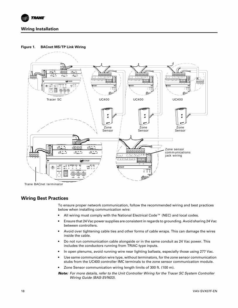
Figure 1. BACnet MS/TP Link Wiring
BI LINK IMC
+VDC
AIAIAI AI AI
P P
TX
RX
LINK IM
SERVI
SERVICE TOOL
IM
BI LINK IMC
+VDC
AIAIAI AI AI
P P
TX
RX
LINK IM
SERVI
SERVICE TOOL
IM
BI LINK IMC
+VDC
AIAIAI AI AI
P P
TX
RX
LINK IM
SERVI
SERVICE TOOL
IM
+
+
BI LINK IMC
+VDC
AIAIAI AI AI
P P
TX
RX
LINK IM
SERVI
SERVICE TOOL
IM
+
BI LINK IMC
+VDC
AIAIAI AI AI
P P
TX
RX
LINK IM
SERVI
SERVICE TOOL
IM
+
Tracer SC UC400 UC400 UC400
Zone Sensor
Zone Sensor
Zone Sensor
Trane BACnet terminator
Zone sensor communications jack wiring
Wiring Best Practices
To ensure proper network communication, follow the recommended wiring and best practices below when installing communication wire:
• All wiring must comply with the National Electrical Code™ (NEC) and local codes.
• Ensure that 24 Vac power supplies are consistent in regards to grounding. Avoid sharing 24 Vac between controllers.
• Avoid over tightening cable ties and other forms of cable wraps. This can damage the wires inside the cable.
• Do not run communication cable alongside or in the same conduit as 24 Vac power. This includes the conductors running from TRIAC-type inputs.
• In open plenums, avoid running wire near lighting ballasts, especially those using 277 Vac.
• Use same communication wire type, without terminators, for the zone sensor communication stubs from the UC400 controller IMC terminals to the zone sensor communication module.
• Zone Sensor communication wiring length limits of 300 ft. (100 m).
Note: For more details, refer to the Unit Controller Wiring for the Tracer SC System Controller Wiring Guide (BAS-SVN03).
18 VAV-SVX07F-EN

Wiring Installation
Setting Up the UC400 Controller on a BACnet Link
Observe the following when setting up the UC400 controller on a BACnet link.
• Use 18 AWG shielded communication wire for BACnet MS/TP installations.
• Limit BACnet MS/TP wiring links to 4,000 ft. There is a maximum of 60 devices per link (without a repeater).
Note: Two (2) BACnet links are available on the Tracer SC.
• Connect the BACnet link to the UC400 controller terminals labeled Link as shown on the right. Incoming wires can be connected to the first two terminals, and the outgoing wires can be connected to the second set of terminals, so there is only one wire per termination. For more details, refer to the Unit Controller Wiring for the Tracer SC System Controller Wiring Guide (BAS-SVN03).
Setting the Address
The three (3) rotary address dials on the UC400 serve one or two purposes depending upon the network: they are always used for the MAC Address, which is sometimes all or part of the BACnet Device ID.
Figure 2.
VAC24
XFRM
BI4AO1
BI5AO2 UI1 UI2
P1 P2
CNCNOBO3
CNCNOBO2
CNCNOBO1
RELAYS
ADDRESS
TRIAC SUPPLY TRIACS
ABO9BO8BO7BO6BO5BO4A BB
TX
RX
LINK IMC
SERVICE
SERVICE TOOL
CONNECT AC POWER TO THE TRAIC SUPPLY TO POWER THE TRIACS
BO1 BO2 BO3 BO4 BO5 BO6 BO7 BO8 BO91 23
45678
9
0
x10
IMC
1
1
3
4567
1 23
45678
9
0
x100
8
9
0
x1
Use a 1/8 inch (3.2 mm) flathead screwdriver to set rotary address dials. These dials rotate in either direction.
Setting the Rotary Address
MAC Address
The MAC Address is required by the RS-485 communication protocol on which BACnet operates. Valid MAC addresses are 001 to 127 for BACnet.
Important:� Each device on the link must have a unique MAC Address/Device ID. A duplicate address or a 000 address setting will interrupt communications and cause the Tracer SC device installation process to fail.
BACnet Device ID
The BACnet Device ID is required by the BACnet network. Each device must have a unique number from 001 to 4094302.
VAV-SVX07F-EN 19
Wiring Installation
BACnet Networks Without a Tracer SC System Controller
On BACnet networks without a Tracer SC system controller, the Device ID can be assigned one of two ways:
• It can be the same number as the MAC Address, determined by the rotary address dials on the UC400 controller. For example, if the rotary address dials are set to 042, both the MAC Address and the BACnet Device ID are 042, OR
• It can be soft set using Tracer TU service tool. If the BACnet Device ID is set using Tracer TU service tool, the rotary address dials only affect the MAC Address, they do not affect the BACnet Device ID. For more details, refer to the Tracer UC400 Controller BACnet Protocol Implementation Conformance Statement (PICS) [BAS-PRG007-EN].
BACnet Networks With a Tracer SC System Controller
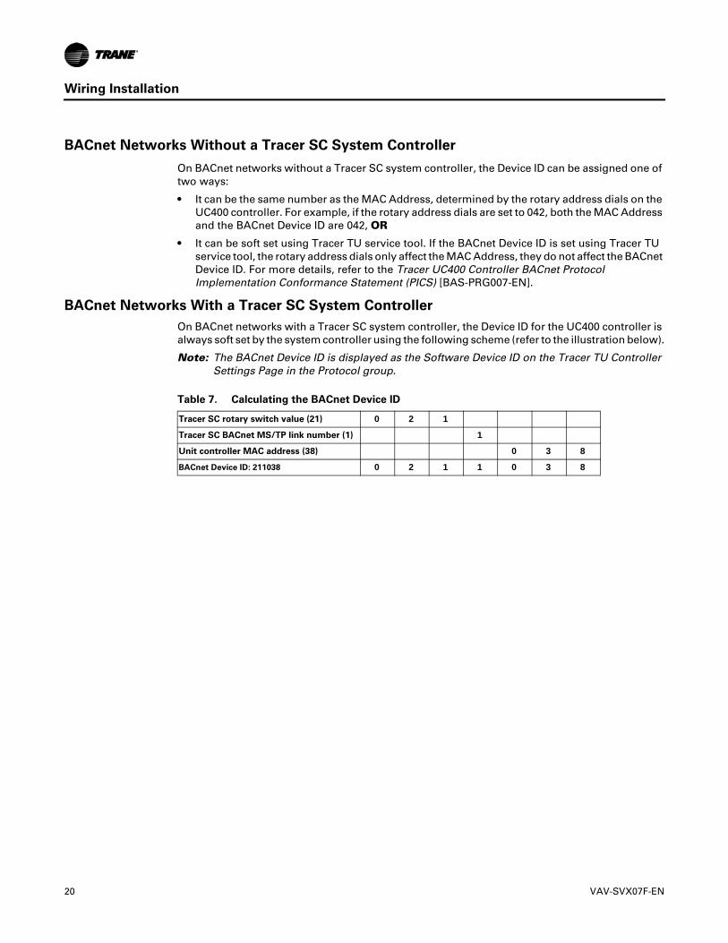
On BACnet networks with a Tracer SC system controller, the Device ID for the UC400 controller is always soft set by the system controller using the following scheme (refer to the illustration below).
Note: The BACnet Device ID is displayed as the Software Device ID on the Tracer TU Controller Settings Page in the Protocol group.
Table 7. Calculating the BACnet Device ID
Tracer SC rotary switch value (21) 0 2 1
Tracer SC BACnet MS/TP link number (1) 1
Unit controller MAC address (38) 0 3 8
BACnet Device ID: 211038 0 2 1 1 0 3 8
20 VAV-SVX07F-EN
Wiring Installation
Wiring Requirements
To ensure proper operation of the UC400 controller, install the power supply circuit in accordance with the following guidelines:
• The controller must receive AC power from a dedicated power circuit.
Important:� Failure to comply may cause the controller to malfunction.
• A dedicated power circuit disconnect switch must be near the controller, easily accessible by the operator, and marked as the disconnecting device for the controller.
• DO NOT run AC power wires in the same wire bundle with input/output wires.
Important:� Failure to comply may cause the controller to malfunction due to electrical noise.
• 18 AWG (0.823 mm2) copper wire is recommended for the circuit between the transformer and the controller.
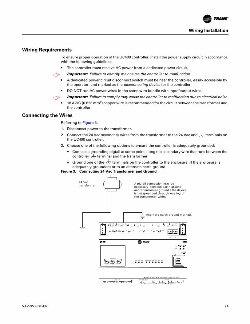
Connecting the Wires
Referring to Figure 3:
1. Disconnect power to the transformer.
2. Connect the 24 Vac secondary wires from the transformer to the 24 Vac and terminals on the UC400 controller.
3. Choose one of the following options to ensure the controller is adequately grounded:
• Connect a grounding pigtail at some point along the secondary wire that runs between the controller terminal and the transformer.
• Ground one of the terminals on the controller to the enclosure (if the enclosure is adequately grounded) or to an alternate earth ground.
Figure 3. Connecting 24 Vac Transformer and Ground
VAC24
XFRMVAC24
VAC24
BI1 BI2 BI3 LINK IMC
+24VDC
BI4AO1
BI5AO2 UI1 UI2 AI3AI2AI1 AI4 AI5
P1 P2
CNCNOBO3
CNCNOBO2
CNCNOBO1
RELAYS
ADDRESS
TRIAC SUPPLY TRIACS
ABO9BO8BO7BO6BO5BO4A BB
TX
RX
LINK IMC
SERVICE
SERVICE TOOL
CONNECT AC POWER TO THE TRAIC SUPPLY TO POWER THE TRIACS
BO1 BO2 BO3 BO4 BO5 BO6 BO7 BO8 BO91 23
45678
9
IMC
1
IMC
1
3
4567
1 23
45678
9
8
9
x1
A pigtail connection may be necessary between earth ground and/or enclosure ground if the device is not grounded through one leg of the transformer wiring.
Alternate earth ground method.
24 Vac transformer
VAV-SVX07F-EN 21
Wiring Installation
Power On Check
1. Verify that the 24 Vac connector and the chassis ground are properly wired.
2. Remove the lockout/tagout from the line voltage power to the electrical cabinet.
3. Energize the transformer to apply power to the UC400 controller.
4. Observe the UC400 controller when power is applied to verify the power check sequence as follows:
a. The power LED lights red for 1 second, then;
b. The power LED lights green.
Note: If the sequence completes as described, the controller is properly booted and ready for the application code. If the power LED flashes red, a fault condition exists.
Application Wiring
This subsection provides information about pre-configured wiring for the following applications:
• “Zone Sensor Wiring”
• “Duct Temperature Sensor Wiring,” p. 24
• “Binary Wiring,” p. 24
Zone Sensor Wiring
Zone Sensor Hard Wired Option
Depending on the zone sensor options used, a maximum of seven (7) wires may be required to run from the UC400 controller to the zone sensor. The zone sensor options are:
• Zone sensor (temperature only); Part Number X1351152801.
• Zone sensor with timed override (TOV) on/cancel button; Part Number X1351153001.
• Zone sensor with adjustable setpoint thumbwheel, Part Number X1351152901.
• Zone sensor with adjustable setpoint thumbwheel, timed override (TOV) on/cancel button; Part Number X1351152701.
• Zone sensor with digital display; Part Number X1379088601.
Note: Display sensor has factory mounted communication module.
• Communications module; Part Number X1365146702, one (1) box of 12.
Zone Sensor Wireless Option
Wireless zone sensors are available individually or on sensor/receiver sets. A receiver is used to receive the signal from the wireless zone sensor and can be factory or field installed. For more details on the setup of wireless zone sensors, refer to the Wireless Zone Sensors for Models WTS, WZS, and WDS Installation, Operation, and Maintenance Manual (BAS-SVX04).
Important:� Currently, wireless sensors do not provide a communication module option. It is recommended that at least one wired sensor with communications module be installed within the network of controllers, for service tool connection.
The wireless zone sensor options are:
• Wireless zone sensor (temperature only)
– Sensor/Receiver Set; Part Number X1379082301
– Sensor only; Part Number X13790821
• Wireless zone sensor with adjustable setpoint thumbwheel (°F), timed override (TOV) on/cancel button
– Sensor/Receiver Set; Part Number X13790496
22 VAV-SVX07F-EN

Wiring Installation
– Sensor only; Part Number X13790492
• Wireless zone sensor with adjustable setpoint thumbwheel (°C), timed override (TOV) on/cancel button
– Sensor/Receiver Set; Part Number X13790498
– Sensor only; Part Number X13790494
• Wireless zone sensor with digital display
– Sensor/Receiver Set; Part Number X1379082401
– Sensor only; Part Number X1379082201
• Wireless receiver only; Part Number X13790854
Zone Sensor Mounting and Wiring
Mounting Location
A zone sensor in each control zone should be located in the most critical area of the zone. Sensors should not be mounted in direct sunlight or in the area supply air stream. Subdivision of the zone may be necessary for adequate control and comfort. Avoid mounting zone sensors in areas subject to the following:
• Drafts or dead spots behind doors or corners.
• Hot or cold air ducts.
• Radiant heat from the sun or appliances.
• Concealed pipes or chimneys.
• Surfaces not heated or cooled behind the sensor such as outside walls.
• Airflows from adjacent zones or other units.
• Avoid locations outside of the operating temperature and the humidity range.
Wiring
Each unit must be controlled by a zone sensor that utilizes a standard 10K at 77°F thermistor for temperature outputs. Field wiring for the zone sensors must meet the following requirements:
• Use 18 to 22 AWG stranded, tinned-copper, shielded, twisted-pair wire, recommended.
• Maximum wire length 300 ft. (91 m).
• All wiring must be in accordance with the NEC and local codes.
• If local codes require enclosed conductors, install the zone sensor wires in the conduit.
• Refer to “Appendix: Typical Trane Factory Wiring Diagrams,” p. 68.
Important:� Control wires and power conductors can never be near each other (except at 90 degrees). Do not run power wired through same conduit as signal wires.
Zone Sensor Communication Stubs
The wire that runs from a zone sensor to a unit controller is commonly referred to as the communication stub. It is the wire that goes from the IMC terminal link on the UC400 controller down to the zone sensor. At least one zone sensor per area or controller network should include the optional communications module. Installing additional sensors with the communications module provides added convenience for the service technician.
Important:� There is no limitation on the number of stubs that can be wired from the UC400 controller. Polarity must be maintained and the length limit is 300 ft (91 m).
The wire for the communication stub must be the same that is used for BACnet communication link wiring. Refer to the section, “Zone Sensor Mounting and Wiring,” p. 23.
VAV-SVX07F-EN 23
Wiring Installation
Duct Temperature Sensor Wiring
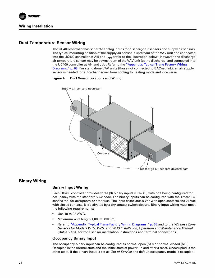
The UC400 controller has separate analog inputs for discharge air sensors and supply air sensors. The typical mounting position of the supply air sensor is upstream of the VAV unit and connected into the UC400 controller at AI5 and (refer to the illustration below). However, the discharge air temperature sensor may be downstream of the VAV unit (at the discharge) and connected into the UC400 controller at AI4 and . Refer to the “Appendix: Typical Trane Factory Wiring Diagrams,” p. 68. For standalone VAV units (those not connected to BACnet link), an air supply sensor is needed for auto-changeover from cooling to heating mode and vice versa.
Figure 4. Duct Sensor Locations and Wiring
Supply air sensor; upstream
Controls
Discharge air sensor; downstream
Binary Wiring
Binary Input Wiring
Each UC400 controller provides three (3) binary inputs (BI1–BI3) with one being configured for occupancy with the standard VAV code. The binary inputs can be configured with the Tracer TU service tool for occupancy or other use. The input associates 0 Vac with open contacts and 24 Vac with closed contacts. It is activated by a dry contact switch closure. Binary input wiring must meet the following requirements:
• Use 18 to 22 AWG.
• Maximum wire length 1,000 ft. (300 m).
• Refer to “Appendix: Typical Trane Factory Wiring Diagrams,” p. 68 and to the Wireless Zone Sensors for Models WTS, WZS, and WDS Installation, Operation and Maintenance Manual (BAS-SVX04) for zone sensor installation instructions and terminal connections.
Occupancy Binary Input
The occupancy binary input can be configured as normal open (NO) or normal closed (NC). Occupied is the normal state and the initial state at power-up and after a reset. Unoccupied is the other state. If the binary input is set as Out of Service, the default occupancy mode is occupied.
24 VAV-SVX07F-EN

Wiring Installation
Binary Output Wiring
Binary outputs that are required for unit operation are factory wired and commissioned. The UC400 controller does have extra binary outputs available for other use with most configurations. To program the extra outputs on the UC400 controller, refer to the Tracer UC400 Programmable Controller Installation, Operation, and Maintenance Manual (BAS-SVX20) and the Application Guide for UC400 VAV Operation (BAS-APG010).
VAV-SVX07F-EN 25
Controller Operation
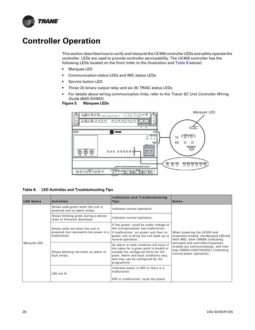
This section describes how to verify and interpret the UC400 controller LEDs and safely operate the controller. LEDs are used to provide controller serviceability. The UC400 controller has the following LEDs located on the front (refer to the illustration and Table 8 below):
• Marquee LED
• Communication status LEDs and IMC status LEDs
• Service button LED
• Three (3) binary output relay and six (6) TRIAC status LEDs
• For details about wiring communication links, refer to the Tracer SC Unit Controller Wiring Guide (BAS-SVN03).
Figure 5. Marquee LEDs
Marquee LED
Table 8. LED Activities and Troubleshooting Tips
LED Name ActivitiesIndication and Troubleshooting Tips Notes
Marquee LED
Shows solid green when the unit is powered and no alarm exists. Indicates normal operation.
When powering the UC400 and expansion module, the Marquee LED will blink RED, blink GREEN (indicating activated and controller/expansion module are communicating), and then stay GREEN CONTINUOSLY (indicating normal power operation).
Shows blinking green during a device reset or firmware download. Indicates normal operation.
Shows solid red when the unit is powered, but represents low power or a malfunction.
If low power; could be under voltage or the microprocessor has malfunction. If malfunction; un-power and then re-power unit to bring the unit back up to normal operation.
Shows blinking red when an alarm or fault exists.
An alarm or fault condition will occur if the value for a given point is invalid or outside the configured limits for the point. Alarm and fault conditions vary, and they can be configured by the programmer.
LED not lit.
Indicates power is OFF or there is a malfunction.
OFF or malfunction; cycle the power.
26 VAV-SVX07F-EN

Controller Operation
Link and IMC
TX blinks green.Blinks at the data transfer rate when the unit transfers data to other devices on the link.
TX LED: Regardless of connectivity or not, this LED will constantly blink as it continually looks for devices to communicate to.
LED not lit:Determine if, for example, a Tracer SC or BACnet device is trying to talk to the controller or if it is capable of talking to the controller. Also determine if the communication status shows down all of the time. In addition, check polarity and baud rate..
RX blinks yellow.
Blinks at the data transfer rate when the unit receives data from other devices on the link.
• ON solid yellow; indicates there is reverse polarity.
LED is not lit.
Indicates that the controller is not detecting communication.
• Not lit; cycle the power to reestablish communication.
Service
Shows solid green when the LED has been pressed.
When the UC400 is placed into boot mode, the system will not run any applications such as trending, scheduling, and TGP2 runtime. The controller is placed into boot mode if the service pin is held in when power is applied. In boot mode, the controller is non-operational and is waiting for a new main application to be downloaded.
LED not lit. Indicates controller is operating normally.
Binary B01 through B09
Shows solid yellow.
Indicates a corresponding binary output has been commanded ON.
• Relay coil; indicates that a command has been made to energize.
• TRIAC; indicates that a command has been made to turn ON.
If the user is currently powering the UC400 from a USB port, the Led lights will turn ON. However, the binary outputs will not be activated.
Commanded ON; As an example of commanded ON, a command could be a manual command such as an override or a command could be from TGP2 based on a list of conditions that are met telling these outputs to turn ON.
LED not lit:Did the user command it to be ON? If yes, see the Marquee LED at the top of this table.
LED not lit.
Indicates that a relay output is de-energized or no power to the board.
• Not lit; cycle power to reestablish communication.
Table 8. LED Activities and Troubleshooting Tips (continued)
LED Name ActivitiesIndication and Troubleshooting Tips Notes
VAV-SVX07F-EN 27

UC400 Controller Points and Parameters
You can use the Tracer TU service tool to view or adjust points and parameters in the Tracer UC400 controller. It is a software application for monitoring, configuring, balancing, and testing Trane unit controllers, such as the Tracer UC400 controller.
Refer to the following documents for product information including an introduction to the Tracer TU service tool, its utilities, screens, concepts, and procedures:
• The Tracer TU Service Tool Getting Started Guide (TTU-SVN01)
• The Tracer TU Help for Programmable Controllers (Online Help included with Tracer TU)
This section contains information about points and parameters specific to VAV configurations. They are grouped according to the Tracer TU utility screens.
• “Status Utility”
• “Equipment Settings,” p. 30
Status Utility
The Status Utility is displayed by default when you start a Tracer TU session. This subsection presents VAV related items you will see on the Unit Summary, Analog, Binary, Multistate, and Controller Status screens.
Unit Summary Screen
Note: Example based on a UC400 configured for Space Temperature Control.
The Tracer TU service tool will launch and display the status of the Tracer UC400 controller. The Unit Summary screen arranges relevant status information under the Operating Status, Space, Ventilation, and Outputs expanding boxes. The following points apply to VAV operations and are explained here.
Operating Status
• Occupancy Status: The Tracer UC400 controller has four (4) valid occupancy modes that display under the operating status– Occupied mode, Unoccupied mode, Occupied Standby mode, and Occupied Bypass mode.
• Heat /Cool Status: The heat/cool status displays the heating and cooling mode of the Tracer UC400 controller. This is where the controller displays the heating or cooling mode of the controller. The controller can receive communicated requests for heating or cooling operation. Responses are: Heat, Cool, Calibrate, and Test. Test will be displayed in air or water valve is being overridden.
• Actual Air Valve Position: Reports air valve position
• Air Valve Position Control: The Tracer UC400 controller displays either pressure dependent or pressure independent status if it has a valid flow input to the controller from the flow ring and pressure transducer. The controller can operate with or without a valid flow value; the airflow is hard wired only. It operates under pressure dependent control or pressure independent control.
– Pressure dependent control: When a valid flow value is not present, the controller operates under pressure dependent control (position control). Pressure dependent control substitutes the air valve position for the flow measurement for all control actions.
– Pressure independent control: When a valid flow value is present, the controller operates under pressure independent control. If after an airflow sensor failure, the airflow returns to the valid range (airflow value greater than 10% of configured nominal airflow), the controller automatically resumes pressure independent control.
• Discharge Airflow: Displays the current discharge airflow when in pressure independent operation.
28 VAV-SVX07F-EN
UC400 Controller Points and Parameters
• Airflow Setpoint (Active): Displays the active airflow setpoint. The airflow setpoint will be determined based on the heat cool mode status, and the required heating or cooling capacity.
• Space CO2 Concentration: CO2-based demand control ventilation uses the space CO2 value. The controller compares the space CO2 concentration to the configured band of CO2 values and determines the demand ventilation rate of the zone. The resulting ventilation rate is called the effective ventilation setpoint. The effective ventilation setpoint is the outdoor airflow required to provide ventilation. It is used to calculate the ventilation ratio of the zone.
Space
• Space Temperature: The temperature, as reported by the zone sensor.
• Space Temperature (Active) Setpoint: The active (or actual) setpoint currently used by the Tracer UC400 controller. Can be either Heating or Cooling depending on operating mode.
• Space Temperature Setpoint BAS: Shows the setpoint being communicated to the VAV unit from a BAS system.
• Space Temperature Setpoint Local: Displays setpoint from local zone sensor.
• Space Temperature Setpoint Default: Displays default configured setpoint.
• Discharge Air Temperature: Shows the discharge air temperature input, which is the temperature of the air leaving the VAV box.
• DA Temperature Setpoint BAS: Displays communicated discharge air temperature setpoint, if valid, when discharge air temperature control reset is enabled.
Ventilation.
• Ventilation Ratio: Required ratio of OA to primary air to meet zone ventilation need.
• Ventilation Setpoint: Arbitrated final value of the zone ventilation requirement.
• Air Flow Stpt Active Min: Displays active minimum flow setpoint.
Note: The UC400 may not be using the minimum flow setpoint if space conditions require more airflow).
• Air Flow Stpt Active Min Source: Displays the current minimum flow setpoint source.
Outputs
• Supply Fan Status: Indicates current fan On/Off status, or None if no fan present.
• Air Valve Position Command: Indicates desired air valve position.
• Heat Output Secondary Status: Indicates Reheat Capacity Status in percentage.
Analog, Binary, and Multi-state Screens
Use the Analog, Binary, and Multi-state screens to view input, output, and value points. These three categories are presented in expanding boxes that stretch across the middle of each screen and are defined from the factory.
Note: For field use of spare analog points, refer to the Tracer UC400 Programmable Controller Installation, Operation, and Maintenance Manual (BAS-SVX20).
VAV-SVX07F-EN 29
UC400 Controller Points and Parameters
Controller Status Screen
Program
The Tracer UC400 controller has up to three (3) TGP2 programs downloaded and defined in the factory as part of the factory commissioning process. The three programs are a base program for damper control, fan, and reheat control. When looking at programming section of Controller Status tab, operation of these programs can be monitored.
Equipment Settings
Use the Equipment Settings set and change a number of equipment setpoints and setup parameters on the Equipment Utility screens.
Setpoints Screen
Default Setpoints
• Unoccupied Cooling Setpoint: Setpoints have a range from 40.0°F to 115.0°F (4.44°C to 46.11°C). This cooling setpoint is used when the UCM is unoccupied. The unoccupied cooling setpoint must be greater than or equal to the unoccupied heating setpoint plus 2.0°F (1.1°C).
• Unoccupied Heating Setpoint: Setpoints have a range from 40.0°F to 115.0°F (4.44°C to 46.11°C). This heating setpoint is used when the UCM is unoccupied. The unoccupied cooling setpoint must be greater than or equal to the unoccupied heating setpoint plus 2.0°F 1.1°C).
• Occupied Offset: Setpoints have a range from 0.9°F to 45°F (-17.27°C to 7.22°C). If a zone sensor thumbwheel setpoint is not being used, this setpoint are added and subtracted from the Space Temperature Setpoint Default to determine the occupied heating and cooling setpoints.
• Standby Offset: Setpoints have a range from 0.9°F to 45°F (-17.27°C to 7.22°C). If a zone sensor thumbwheel setpoint is not being used, this setpoint are added and subtracted from the Space Temperature Setpoint Default to determine the standby heating and cooling setpoints.
• Space Temperature Setpoint Default: Setpoints have a range from 40.0°F to 115.0°F (4.44°C to 46.11°C). If a zone sensor thumbwheel setpoint is not being used, this setpoint is used as the active cooling setpoint during occupied times for the UCMs. The cooling setpoint must be greater than or equal to the heating setpoint plus 2.0°F (1.1°C).
Setpoint Limits
Each point has its own min/max, therefore, the following setpoint limits are incorporated in the occupied setpoint point, standby setpoint point, and unoccupied heat/cool setpoints. After the controller completes all setpoint calculations, the calculated occupied setpoint is validated against these configured space setpoint limits:
• Heating Setpoint High Limit
• Heating Setpoint Low Limit
• Cooling Setpoint High Limit
• Cooling Setpoint Low Limit
These setpoint limits apply only to the occupied and occupied standby, heating and cooling setpoints. They do not apply to the unoccupied heating and cooling setpoints. When the controller is in the unoccupied mode, it always uses the unoccupied heating and cooling setpoints. Unit configuration enables or disables the local (hard-wired) setpoint. This parameter provides additional flexibility to allow the user to apply communicated, hard wired, or default setpoints without making physical changes to the unit. Similar to hard-wired setpoints, the effective setpoint value for a communicated setpoint is determined based on the stored default setpoints, configuration values, and the controller occupancy mode.
30 VAV-SVX07F-EN

UC400 Controller Points and Parameters
Setup Parameters Screen
Device
Wireless Sensor Enable/Disable: Enables controllers to use wireless sensors in conjunction with a Wireless Communication Interface (WCI) [enabled by default]. When unchecked, only wired sensors or wireless sensors using Wireless Receiver Modules (WRM) are allowed.
Space Temperature Source: The drop-down menu is used to select the source of the controllers space temperature value. Choices are Local Source and BAS.
Occupancy Request Source: The drop-down menu is used to select the source of the controllers Occupancy Request. Choices are Local Source and BAS.
VAV Setup
• Airflow Nominal Status: Nominal flow is the total airflow capacity of the VAV box. Nominal Flow becomes an active field when Generic is selected in Box Size under Equipment Options on the Configuration page. Select the CFM nominal flow for the unit. This is normally used when mounting the tracer UC400 controller on someone else's VAV unit.
• Unit Flow Gain: The flow gain is a multiplier used to calibrate the value reported by the flow sensor so that the reported airflow matches the actual airflow. Typically, it is not necessary to change this value. For Trane units, the nominal airflow and unit flow gain are based on unit size and are not adjustable. The default unit flow gain for generic VAV boxes is 1.0.
• Airflow Measurement Offset: The flow offset is used to calibrate the value reported by the flow sensor so that the reported flow matches the actual flow. The flow offset is determined during the air balancing process. A test-and-balance professional will use the Tracer TU Air and Water Balance tool to calculate this value and balance the VAV box. Typically, it is not necessary to change this value.
Note: The flow offset is calculated only for two-point balancing, which requires reading both the maximum and minimum airflows during balancing. Two-point balancing ensures greater accuracy over the entire range of air valve operation.
• Airflow Gain: The airflow gain is used to calibrate the value reported by the flow sensor so that the reported airflow matches the actual airflow. The flow gain is determined during the air balancing process. A test-and-balance professional will use the TU Air and Water Balance tool to calculate this value and balance the VAV box. Typically, it is not necessary to change this value.
Ventilation Setup
• Ventilation Setpoint Local: The Tracer SC BAS uses the ventilation setpoint from all the VAV boxes to calculate how much outdoor air (OA) the system needs. During the occupied mode, this setpoint is the active setpoint for ventilation, and should be equal to the ventilation airflow required at design occupancy of the space.
• Ventilation Standby Setpoint: During the occupied standby mode, this setpoint is the active setpoint for ventilation.
Space CO2 Setup
• Space CO2 Low Limit: The controller adjusts the ventilation setpoint based on the current CO2 concentration. When the concentration is less than or equal to this low limit, the zone is most likely unoccupied and the ventilation setpoint is set equal to Ventilation Standby Setpoint. When the concentration is between the low and high limits, the ventilation setpoint is adjusted proportionally between Ventilation Standby Setpoint and Ventilation Setpoint Local.
• Space CO2 High Limit: The controller adjusts the ventilation setpoint based on the current CO2 concentration. When the concentration is greater than or equal to this high limit, the zone is most likely at design occupancy and the ventilation setpoint is set equal to Ventilation Setpoint Local.
VAV-SVX07F-EN 31
UC400 Controller Points and Parameters
Flow Setpoints Setup
• Airflow Setpoint Minimum: Although the UCM will read flow down to 5% of cataloged, the range of MIN FLOW settings is 0% or 10% to 100% of cataloged. The UCM will not drive its flow below this minimum flow value under normal operating conditions while in the cool mode. Cool mode occurs when cool air is in the supply duct. The entry in this field must be less than or equal to the entry in the Airflow Setpoint Maximum field.
• Airflow Setpoint Maximum: This range is 10% to 100% of the cataloged unit CFM size. Cooling and heating flow can be edited to zero.The UCM will not drive its flow above this maximum flow value under normal operating conditions while in the Cool mode. Cool mode occurs when cool air is in the supply duct. The entry in this field must be greater than or equal to the entry in any of the Minimum fields.
• Standby Minimum Airflow: Occupied standby mode is used to reduce the heating and cooling demands during the occupied hours when the space is temporarily unoccupied. For example, it can be activated for a classroom currently not in use. Standby Minimum is the minimum amount of airflow desired during this mode.
• Airflow Setpoint Minimum Standby Heat: Occupied standby mode is used to reduce the heating and cooling demands during the occupied hours when the space is temporarily unoccupied. For example, it can be activated for a classroom currently not in use. Airflow Setpoint Minimum Standby Heating is the minimum amount of airflow desired when in the heat mode during this mode.
• Airflow Setpoint Minimum Heat: The UCM will not drive its position/flow below this value under normal operating conditions while in the HEAT mode (warm air in the supply duct) or while it is using local heat.
• Airflow Setpoint Maximum Heat: The controller enters maximum flow heat on receipt of a communicated command and remains in Airflow Setpoint Maximum Heat until the command changes. The controller maintains the flow rate at the heating maximum airflow. This is normally used with a rooftop unit with staged heat that needs a Max constant volume of air movement to keep the heat exchanger from overheating and tripping the heat in the rooftop unit tripping on a high limit safety.
• Airflow Setpoint Minimum Local Heat: If the Min Local Heat flow is enabled, then this Minimum Local Heat setpoint is used to determine the minimum position/flow instead of the Airflow Setpoint Minimum Heat when local heat is on. This entry must be less than or equal to the entry for Airflow Setpoint Maximum Heat.
Discharge Air Reset Limits:
The following parameters are used for Single Duct Units that are equipped with either modulating hot water reheat or SCR electric heat, which allows variable airflow when reheat is activated (for example, “dual maximums” control sequence).
• Airflow Setpoint Reset Minimum Local Heat: The minimum position/flow when local heat (either modulating hot water or SCR electric) is on. This entry must be less than or equal to the entry for Airflow Setpoint Reset Maximum Local Heat. When reheat is initially activated the air valve opens to, and remains at, this minimum position/flow setpoint, while reheat capacity is modulated to maintain the space temperature at the active heating setpoint. Once reheat capacity has increased to the point that the discharge air temperature reaches the Discharge Air Temperature Design Setpoint, the controller will begin to increase airflow above this minimum setpoint.
• Airflow Setpoint Reset Maximum Local Heat: The maximum position/flow when local heat (either modulating hot water or SCR electric) is on. This entry must be greater than or equal to the entry for Airflow Setpoint Reset Minimum Local Heat. Once reheat capacity has increased to the point that the discharge air temperature has reached the Discharge Air Temperature Design Setpoint, the controller will begin to increase airflow above Airflow Setpoint Reset Minimum Local Heat. If the air valve reaches this maximum setpoint, reheat capacity is allowed
32 VAV-SVX07F-EN
UC400 Controller Points and Parameters
to increase further, raising the discharge air temperature, while the air valve remains at Airflow Setpoint Reset Maximum Local Heat.
• Discharge Air Temperature Reset Maximum: This is the maximum discharge air temperature allowed when local heat (either modulating hot water or SCR electric) is on. Once the controller has increased airflow to Airflow Setpoint Reset Maximum Local Heat, reheat capacity is allowed to increase further, raising the discharge air temperature, but not above this maximum limit.
• Discharge Air Temperature Design Setpoint: When local heat (either modulating hot water or SCR electric) is initially activated, the air valve will maintain position/flow at Airflow Setpoint Reset Minimum Local Heat and begin increasing reheat capacity. Once reheat capacity has increased to the point that the discharge air temperature has reached this design setpoint, the controller will begin to modulate airflow between Airflow Setpoint Reset Minimum Local Heat and Airflow Setpoint Reset Maximum Local Heat, while reheat capacity is modulated to maintain the discharge air temperature at this design setpoint.
Note: When the parameters on this tab are used, leave Airflow Setpoint Minimum Local Heat (found in the Flow Setpoints Setup section) at the factory configured value. If there is a fault with the discharge air temperature sensor, the controller reverts to Airflow Setpoint Minimum Local Heat when local heat is on.
Commissioning Screen
Actions
• Zero Air and Water Valve Position (Start Button): The calibration sequence enables the controller to calibrate the air valve position and the water valve position, as well as calibrate the flow sensor.
• Auto-commissioning (Start Button): The controller auto-commissioning test sequence validates both the proper operation of all outputs and the capability to measure all inputs. The purpose of the test sequence is to minimize the labor required to commission the unit in the field.
The auto-commissioning test does not require a flow sensor or a discharge or supply air temperature sensor. If there is no flow sensor, the controller runs in pressure-dependent mode. A temperature sensor in the discharge air stream is required for testing of the fan and the reheat. The fan and the reheat are not tested if the discharge air temperature sensor is not present. The fan is not tested if there is no fan. Local reheat is tested, if it is present. Remote reheat is not tested.
The sequence starts on receipt of an auto-commission command from the Tracer TU service tool start button or the Tracer SC. The auto-commission command contains a time/date stamp. No 3rd party tool can start the auto-commissioning sequence. The user then chooses to commission all VAV boxes or one VAV box. The results of auto-commissioning are contained in a structured network variable called reported auto commissioning report. The controller places the time/date stamp in the report. The structure is loaded with the default values for all of the fields when the auto commissioning test sequence starts. The fields are updated with the results as the sequence progresses. The data is held until the next auto-commissioning test.
If an auto-commission command is received in the middle of an auto-commissioning cycle, the auto-commissioning sequence restarts. If an auto-commission command is received during calibration, calibration aborts and restarts after auto-commissioning finishes. If an abort auto-commission command is received during the calibration portion of the primary air valve test, it is honored after the air valve calibration finishes.
VAV-SVX07F-EN 33

UC400 Controller Points and Parameters
• Calibrate Air Valve (Start Button): Displays the Calibrate Air Valve dialog box. Use this air balancing tool to perform a basic two-point air balance for the Tracer UC400 controller. See the Tracer TU Help for Programmable Controllers (“Configuring and Commissioning Equipment” > “VAV Boxes” > “Using the Air Balancing Tool”) for the correct procedure.
Note: A full discussion of air balancing is beyond the scope of this document. Refer to the Air Systems for Tracer SC Applications Guide (BAS-APG007).
• Airflow Override: Displays the Airflow Override dialog box. The user can override the air damper to open for a limited duration as part of a system water balancing operation. When the timed duration expires, the water valve is released back to its normal setting.
• Water Valve Override: Displays the Water Valve Override dialog box. The user can override the water valve to open for a limited duration as part of a system water balancing operation. When the timed duration expires, the water valve is released back to its normal setting.
• Fan Override: Displays the Fan Override dialog box, which can be used to override the fan setting to On.
Note: For ECM fans, the user can also select the speed of when the fan turns on.
Operating Status
This box includes view only settings related to air flow. Two fan output settings can be overridden.
ECM Fan Setup
(Visible if an ECM fan is configured.) This box includes flow setpoint, maximum and minimum flow settings, and a correction factor setting.
Current Calibration Summary
Presents the results of the two point air valve calibration along with the Minimum and Maximum Air Flow Setpoints.
Discharge Air Reset Limits
This box contains settings that are used for Dual max VAV boxes. When the VAV’s heating valve is open, the box flow will modulate between the flow settings to control to the Discharge Air Temp Design Setpoint.
Configuration Screen
Application Selection
• Profile: This allows for selection between three operational programs. The three programs are Space Temperature, Ventilation Flow, and Flow Tracking.
Equipment Options
• Box Size: Used to select a Trane F-style box size or Generic Box.
• Air Damper Opens: Chose between Clockwise and Counter-Clockwise damper rotation to open the damper.
• Fan Control: Choices are None, Parallel, and Series. If Parallel or Series is selected the Fan Setting group box will appear.
•
• Reheat Type: Choose between reheat options of None, Hot Water, or Electric heat. If Hot Water or Electric heat are selected the Reheat Settings group box will appear.
• Parallel Fan Control: This entry will determine if a parallel fan is controlled based on zone temperature or on flow conditions. The entry field on this line will disappear if the unit does not have a parallel fan.
34 VAV-SVX07F-EN

UC400 Controller Points and Parameters
Reheat Settings
• Valve Control Type (Hydronic): The choices are two-position, modulating, or both.
• Location of Reheat: Choices are Local and Remote. If Both is selected for Valve Control Type, this is used to select the location of the 2-Position valve.There is an additional binary value point to select whether local or remote reheat has priority. By selecting Local the VAV unit will use local reheat before remote reheat. If Remote is selected it does the opposite in that the VAV unit will use remote heat before local heat.
• Heat Control Type (Electric): Choices are Pulse Width Modulation, Staged, and SCR. Chose the correct electric heat type.
• Number of Reheat Stages (PWM or Staged): Choose the correct number of reheat stages (1-3)
Sensor Options
If a UC400 has a wireless zone sensor and is a member of Tracer SC wireless link, you can install this feature to configure the unit controller so it will communicate the wireless zone sensor battery level to the Tracer SC once it is installed on the Tracer SC. An alarm will be activated in response to a predefined “replace batteries” state of the point.
VAV-SVX07F-EN 35
Calibration, Operation Modes, and Control
This section provides information about:
• “Calibration”
• “Occupancy Modes,” p. 36
• “Space Temperature Control (STC) for Single Duct and Fan-powered Units,” p. 38
• “Ventilation Flow Control (VFC),” p. 45
• “Flow Tracking (FTC),” p. 48
Calibration
The calibration sequence enables the controller to calibrate both, the air valve position and the water valve position. Calibration takes place if auto-calibration is enabled and either a power cycle or a transition from occupied to unoccupied has occurred.
Note: Whether or not auto-calibration is enabled, the controller initiates calibration on a communicated application mode command.
The building automation system is responsible for the staggering of the calibration sequence that is needed between units. When auto-calibration is enabled, and a transition from occupied to unoccupied occurs, the calibration sequence starts after a fixed delay of three (3) minutes. The controller effective occupancy mode is unoccupied, but runs as if it is occupied during this three- minute period.
The mode field of reported unit status reports calibration when the controller is in the calibration sequence. If auto-calibration is disabled, the air valve and water valve are not driven closed and the flow sensor zero flow voltage reading is not recorded. Refer to following table for calibration actions.
I/O Device Calibration Action Taken Result After Calibration
Air valve Drive the air valve closed to the stroke time, plus 20 seconds.
Initialize the air valve position as closed when the air valve is over-driven.
Flow sensor Record the flow reading when the air valve is fully closed. Subtract the zero flow reading from all subsequent readings.
Modulating hot water reheat
Drive the water valve closed for the stroke time, plus 20 seconds.
Initialize the water valve position as closed when the water valve is over-driven.
Fan Enabled Enabled
Electric or On/Off hot water Disabled Enabled
Occupancy Modes
TGP2 programs have four (4) valid occupancy modes:
• Occupied mode
• Unoccupied mode
• Occupied standby mode
• Occupied bypass mode
Occupied Mode
Occupied mode is the normal (default) operating mode for occupied spaces or daytime operation. When the controller is in the occupied mode, it uses occupied setpoints and is controlled by:
• Occupied space temperature control
• Ventilation flow control (constant volume with discharge air temperature control)
• Flow tracking control (has no occupancy)
36 VAV-SVX07F-EN
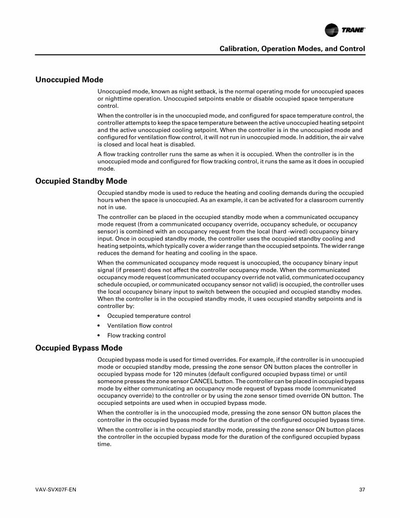
Calibration, Operation Modes, and Control
Unoccupied Mode
Unoccupied mode, known as night setback, is the normal operating mode for unoccupied spaces or nighttime operation. Unoccupied setpoints enable or disable occupied space temperature control.
When the controller is in the unoccupied mode, and configured for space temperature control, the controller attempts to keep the space temperature between the active unoccupied heating setpoint and the active unoccupied cooling setpoint. When the controller is in the unoccupied mode and configured for ventilation flow control, it will not run in unoccupied mode. In addition, the air valve is closed and local heat is disabled.
A flow tracking controller runs the same as when it is occupied. When the controller is in the unoccupied mode and configured for flow tracking control, it runs the same as it does in occupied mode.
Occupied Standby Mode
Occupied standby mode is used to reduce the heating and cooling demands during the occupied hours when the space is unoccupied. As an example, it can be activated for a classroom currently not in use.
The controller can be placed in the occupied standby mode when a communicated occupancy mode request (from a communicated occupancy override, occupancy schedule, or occupancy sensor) is combined with an occupancy request from the local (hard -wired) occupancy binary input. Once in occupied standby mode, the controller uses the occupied standby cooling and heating setpoints, which typically cover a wider range than the occupied setpoints. The wider range reduces the demand for heating and cooling in the space.
When the communicated occupancy mode request is unoccupied, the occupancy binary input signal (if present) does not affect the controller occupancy mode. When the communicated occupancy mode request (communicated occupancy override not valid, communicated occupancy schedule occupied, or communicated occupancy sensor not valid) is occupied, the controller uses the local occupancy binary input to switch between the occupied and occupied standby modes. When the controller is in the occupied standby mode, it uses occupied standby setpoints and is controller by:
• Occupied temperature control
• Ventilation flow control
• Flow tracking control
Occupied Bypass Mode
Occupied bypass mode is used for timed overrides. For example, if the controller is in unoccupied mode or occupied standby mode, pressing the zone sensor ON button places the controller in occupied bypass mode for 120 minutes (default configured occupied bypass time) or until someone presses the zone sensor CANCEL button. The controller can be placed in occupied bypass mode by either communicating an occupancy mode request of bypass mode (communicated occupancy override) to the controller or by using the zone sensor timed override ON button. The occupied setpoints are used when in occupied bypass mode.
When the controller is in the unoccupied mode, pressing the zone sensor ON button places the controller in the occupied bypass mode for the duration of the configured occupied bypass time.
When the controller is in the occupied standby mode, pressing the zone sensor ON button places the controller in the occupied bypass mode for the duration of the configured occupied bypass time.
VAV-SVX07F-EN 37
Calibration, Operation Modes, and Control
Space Temperature Control (STC) for Single Duct and Fan-powered
Units
Single Duct Units
Space Temperature Control Mode
Space temperature control is one of three supported control algorithms (the other two supported control algorithms are “Ventilation Flow Control (VFC),” p. 45 and “Flow Tracking (FTC),” p. 48). Space temperature control requires a valid space temperature. If there is no valid space temperature (either communicated, local, or default), the space temperature control algorithm does not run and the unit either shuts down or goes into construction mode.
The controller heat/cool mode is determined by either a communicated request or by the controller itself. When the heat/cool mode request is AUTO, the controller compares the space temperature with the active space setpoint to determine the heat/cool mode status.
In addition, the controller compares the active space temperature setpoint and the active space temperature and calculates the desired capacity need to bring the space temperature up or down to the space temperature setpoint. The controller positions the modulating air valve to deliver the required airflow based on cooling or heating capacity required.
Cooling Operation
Under space temperature control during the cooling mode (communicated heat/cool mode is cool), the controller attempts to maintain the active space temperature at the active space temperature setpoint. Based on the controller occupancy mode, the active space temperature setpoint is determined based on the occupied or standby offset being added to the communicated, local or default setpoint, the occupied standby cooling setpoint, or the unoccupied cooling setpoint is used.
The outputs are controlled based on the unit configuration and the required cooling capacity. At 0% required cooling capacity, the air valve is at the active minimum flow setpoint. As the required cooling capacity increases, the air valve opens above the minimum position. At 100% required cooling capacity, the air valve opens to the maximum position or to the active maximum flow setpoint.
All units have a modulating air valve that is used to control the volume of airflow through the diffusers and into the space. Modulating the volume of air modulates the unit cooling capacity.
Heating Operation
Under space temperature control during the heating mode (heat/cool mode is heat the space temperature is below the active space temperature setpoint and the heat cool mode request is AUTO), the controller attempts to maintain the space temperature at the active space temperature setpoint. Based on the controller occupancy mode, the active space temperature setpoint is determined based on the occupied or standby offset being subtracted from the communicated, local or default space temperature setpoint or the unoccupied heat setpoint is used. All ventilation requirements are in force during occupied heating and cooling.
The outputs are controlled based on the unit configuration and the required heating capacity. At 0% required heating capacity, the air valve is at its heating minimum or local heating minimum flow setpoint. As the required heating capacity increases, the air valve opens above its minimum position. At 100% required heating capacity, the air valve opens to its maximum position.
38 VAV-SVX07F-EN
Calibration, Operation Modes, and Control
All units have a modulating air valve that is used to control how much air is flowing through the diffusers and into the space. By modulating the volume of airflow, the unit heating capacity is modulated.
Reheat Enable Setpoint
Units may have local or remote reheat, which may be hydronic or electric. Reheat is turned on when the space temperature is below the active space temperature setpoint, and the supply air temperature is below the reheat enable setpoint. Reheat is used to maintain the space temperature at the heating setpoint. Heating operation and Reheat are two different entities.
Auto-changeover
The auto-changeover feature is used if the RTU has heat and the UC400 has a valid local or communicated Supply Air Temperature. If the supply air temperature reaches the Auto-changeover Point, then the air valve control changes from cooling control action to heating control action.
In cooling control action, the air valve modulates between the Airflow Setpoint Minimum and Airflow Setpoint Maximum to meet the required cooling capacity. In heating control action, the air valve modulates between Airflow Setpoint Minimum Heat and Airflow Setpoint Maximum Heat to meet the required heating capacity. Essentially, the RTU is providing heat to the space. If the heating capacity increases, the air valve modulates further open to provide more hot air to the space.
Air Valve Control in Space Temperature Control Operation
Air delivered to the space is controlled with a three-wire, floating-point actuator that modulates the air valve. The controller positions the modulating air valve to deliver the desired airflow (cooling or heating capacity).
The desired airflow is called the active flow setpoint. The controller positions the modulating air valve to deliver the desired airflow (cooling and heating capacity) to within +/-2% of nominal airflow. For example, if the nominal airflow of the box is 900 CFM, the air valve is controlled to maintain flow within +/- 18 CFM of the airflow setpoint.
The airflow control algorithm compares the active airflow setpoint with the measured airflow and calculates the necessary air valve movement to minimize error. The airflow setpoint is limited by applicable minimum and maximum flow setpoints.
Reheat Control
There are two (2) types of reheat control:
• Hydronic heat
• Electric heat
Reheat is allowed to turn ON if the zone temperature is below the heating setpoint. Space temperature control can use reheat if the following conditions are all TRUE:
– The unit is not calibrating
– Heat Cool Mode Status is heat
– For local reheat only, the fan, if present, is not being overridden to Off (communicated fan override)
– The supply air temperature is less than the configured reheat enable setpoint
– For electric reheat, the unit is in Pressure Independent mode or the Pressure Dependent Mode Reheat Enable point is enabled.
VAV-SVX07F-EN 39

Calibration, Operation Modes, and Control
CAUTION
Safety and Maintenance!
Trane does not recommend enabling electric reheat in pressure dependent mode. There are potential safety and maintenance issues that can occur if the electric reheat is allowed to energize when the airflow passing over the element is too low or is below the Airflow Setpoint Minimum Local Heat. Refer to the equipment catalog for Trane F-Style VAV boxes for minimum airflow settings based on box inlet size and heating element kW.
Electric Heat
Electric Heat Pulse-width Modulation (PWM)
Single-duct units can have from one to three stages of electric heat pulse-width modulation. Fan powered units can have up to three stages of electric heat pulse-width modulation. Energizing for a portion of a three-minute time period modulates the electric heater. This allows exact load matching for energy efficient operation, and optimum zone temperature control. The Airflow Setpoint Minimum Local Heat is enforced during reheat. The amount of reheat supplied is dependent on both the degrees that the space temperature is below the active heating setpoint and the time that the space temperature has been below the active heating setpoint. If not already OFF, reheat de-energizes when the zone temperature rises more than 0.5°F (0.28°C) above the heating setpoint. When reheat is de-energized, the cooling Airflow Setpoint Minimum is enforced.
• Stage 1; the ON time is proportional to the amount of reheat required. For example, when 50% of stage 1 capacity is required, reheat is ON for 90 seconds and OFF for 90 seconds. When 75% of stage 1 capacity is required, reheat is ON for 135 seconds and OFF for 45 seconds. When 100% of stage 1 capacity is required, reheat is ON continuously.
• Stages 2 and 3; the same ON time logic as stage 1, except stage 1 is always energized. For example, when 75% of unit capacity is required, stage 1 is energized continuously, and stage 2 is ON for 90 seconds and OFF for 90 seconds.
Electric Heat SCR
SCR is a heat controller that controls a single stage electric heater proportional to an analog signal. The analog output signal is proportional to the amount of reheat required. Typically with SCR heat, the heater is turned on and off on a very short cycle time to provide proportional control of heat output. This allows for closer matching of heating capacity to the heating load, resulting in more stable temperature control.
When the space requires cooling, the air valve modulates between Airflow Setpoint Maximum and Airflow Setpoint Minimum, to maintain space temperature at the active cooling setpoint; and the electric heater is off. When the cooling load has decreased to the point where the air valve has reached Airflow Setpoint Minimum, space temperature is allowed to drift downward, in the deadband between the active cooling setpoint and active heating setpoint.
When the space temperature drops below the active heating setpoint, the air valve opens to the Airflow Setpoint Reset Minimum Local Heat and the SCR controls the electric heater to maintain space temperature at the active heating setpoint. SCR control is dependent on the degree that the space temperature is below the active heating setpoint and the amount of time that the space temperature has been below the active heating setpoint.
If the discharge air temperature reaches the Discharge Air Temperature Design Setpoint, the air valve opens further and modulates between Airflow Setpoint Reset Minimum Local Heat and Airflow Setpoint Reset Maximum Local Heat to maintain space temperature at the active heating setpoint, while the SCR controls the electric heater to maintain discharge air temperature at the Discharge Air Temperature Design Setpoint (see Figure 6, p. 41). If the air valve reaches Airflow Setpoint Reset Maximum Local Heat, the SCR controls the electric heater to maintain space temperature at the active heating setpoint, while the air valve remains at Airflow Setpoint Reset Maximum Local Heat.
40 VAV-SVX07F-EN

Calibration, Operation Modes, and Control
Figure 6. Single Duct VAV Unit with Modulating Hot Water or SCR Electric Heat
Reheat de-energizes when the space temperature rises more than 0.5°F (0.28°C) above the heating setpoint. When reheat is de-energized, the cooling Airflow Minimum Setpoint is enforced.
The Trane VAV unit's SCR electric heater module takes a 0-to-10 Vdc control signal from AO2. Any signal less than 0.2 Vdc, and the heater is turned off. For a signal between 0.2 and 10 Vdc, the heater is on and modulated up to 100% capacity.
Important: Discharge air temperatures should not exceed between 100°F and 110°F, with a temperature between 85°F and 95°F being optimal for space temperature control. If air that is too hot is delivered to the space through ceiling-mounted diffusers, and then leaves the space through ceiling-mounted return-air grilles, the buoyancy of this hot air will tend to cause some of the air to bypass from the supply-air diffusers to the return-air grilles, resulting in uneven air distribution and possible comfort complaints. Refer to Table 9 and Table 10, p. 42 for fan powered reheat.
Table 9. Local Heat Only With No Fan Present
Configuration Method of Control
Local Remote Stage 1 Stage2 Stage 3
PWM electric(1 to 3 stages) Not applicable
• Local PI capacity loop• Each stage represents an equal percentage of total capacity PWM Output (one stage = 100%; two stages =
50% each; three stages = 33.33% each)• Total capacity is limited by communicated supply heat control
SCR electric Not applicable• Local PI capacity loop• SCR heat capacity = total capacity• Total capacity limited by
communicated supply heat control
Not applicable Not applicable
On/Off electric(1 to 3 stages) Not applicable
Local thermostatic:• On: Zt < HSP• Off: Zt HSP + 0.5 °F (0.28°C)
Local thermostatic:• On: Zt <HSP - 1°F (0.56°C)• Off: Zt HSP - 0.5°F (0.28°C)
Local thermostatic:• On: Zt < HSP - 2°F• Off: Zt HSP - 1.5°F (16.9°C)
Each stage represents an equal percentage of total capacity. Total capacity is limited by communicated supply heat control.
VAV-SVX07F-EN 41
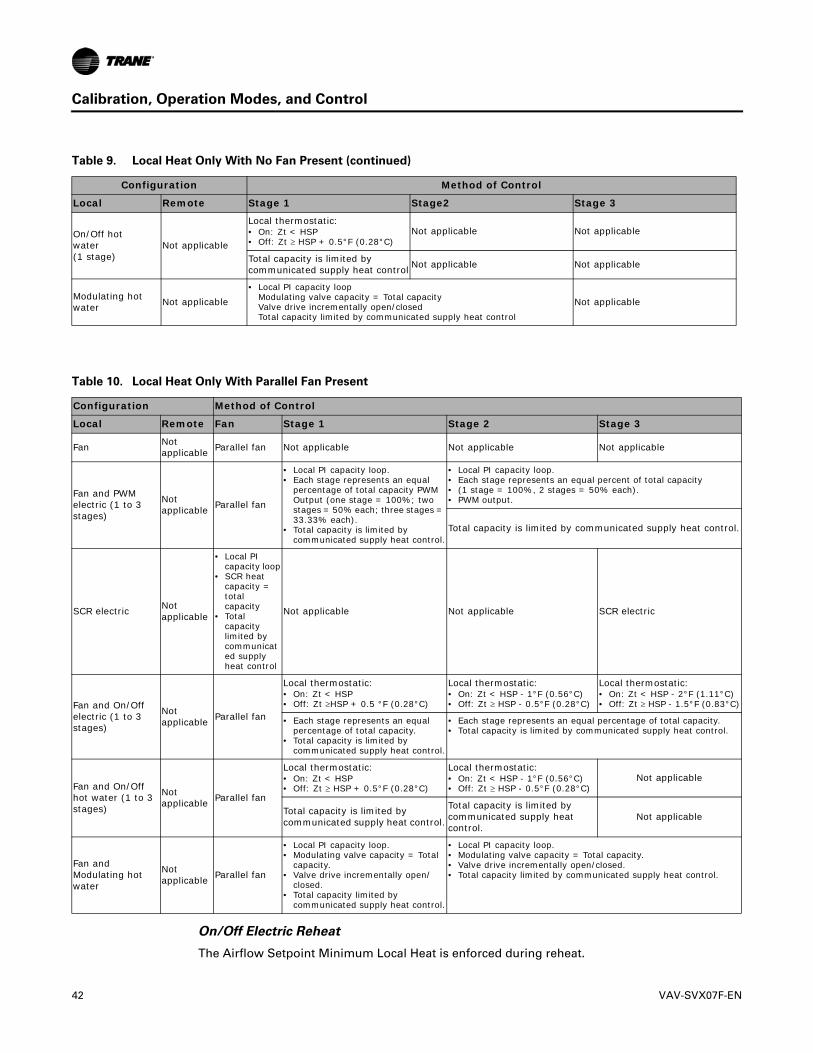
Calibration, Operation Modes, and Control
On/Off Electric Reheat
The Airflow Setpoint Minimum Local Heat is enforced during reheat.
On/Off hotwater(1 stage)
Not applicable
Local thermostatic:• On: Zt < HSP• Off: Zt HSP + 0.5°F (0.28°C)
Not applicable Not applicable
Total capacity is limited by communicated supply heat control Not applicable Not applicable
Modulating hotwater Not applicable
• Local PI capacity loopModulating valve capacity = Total capacity Valve drive incrementally open/closed Total capacity limited by communicated supply heat control
Not applicable
Table 10. Local Heat Only With Parallel Fan Present
Configuration Method of Control
Local Remote Fan Stage 1 Stage 2 Stage 3
Fan Not applicable Parallel fan Not applicable Not applicable Not applicable
Fan and PWM electric (1 to 3 stages)
Not applicable Parallel fan
• Local PI capacity loop.• Each stage represents an equal
percentage of total capacity PWM Output (one stage = 100%; two stages = 50% each; three stages = 33.33% each).
• Total capacity is limited by communicated supply heat control.
• Local PI capacity loop.• Each stage represents an equal percent of total capacity• (1 stage = 100%, 2 stages = 50% each).• PWM output.
Total capacity is limited by communicated supply heat control.
SCR electric Not applicable
• Local PI capacity loop
• SCR heat capacity = total capacity
• Total capacity limited by communicated supply heat control
Not applicable Not applicable SCR electric
Fan and On/Off electric (1 to 3 stages)
Not applicable Parallel fan
Local thermostatic:• On: Zt < HSP• Off: Zt HSP + 0.5 °F (0.28°C)
Local thermostatic:• On: Zt < HSP - 1°F (0.56°C)• Off: Zt HSP - 0.5°F (0.28°C)
Local thermostatic:• On: Zt < HSP - 2°F (1.11°C) • Off: Zt HSP - 1.5°F (0.83°C)
• Each stage represents an equal percentage of total capacity.
• Total capacity is limited by communicated supply heat control.
• Each stage represents an equal percentage of total capacity.• Total capacity is limited by communicated supply heat control.
Fan and On/Off hot water (1 to 3 stages)
Not applicable Parallel fan
Local thermostatic:• On: Zt < HSP• Off: Zt HSP + 0.5°F (0.28°C)
Local thermostatic:• On: Zt < HSP - 1°F (0.56°C)• Off: Zt HSP - 0.5°F (0.28°C)
Not applicable
Total capacity is limited by communicated supply heat control.
Total capacity is limited by communicated supply heat control.
Not applicable
Fan and Modulating hot water
Not applicable Parallel fan
• Local PI capacity loop.• Modulating valve capacity = Total
capacity.• Valve drive incrementally open/
closed.• Total capacity limited by
communicated supply heat control.
• Local PI capacity loop.• Modulating valve capacity = Total capacity.• Valve drive incrementally open/closed.• Total capacity limited by communicated supply heat control.
Table 9. Local Heat Only With No Fan Present (continued)
Configuration Method of Control
Local Remote Stage 1 Stage2 Stage 3
42 VAV-SVX07F-EN

Calibration, Operation Modes, and Control
• Stage 1; energizes when the space temperature falls below the active heating setpoint and minimum airflow requirements are met. When the zone temperature rises above the active heating setpoint by 0.5°F (0.28°C), stage 1 is de-energized.
• Stage 2; energizes when the space temperature is 1°F (0.56°C) or more below the active heating setpoint, and is de-energized when the space temperature is 0.5°F (0.28°C) below the active heating setpoint.
• Stage 3; energizes when the zone temperature is 2°F (1.11°C) or more below the active heating setpoint, and de-energizes when the space temperature is 1.5°F (0.83°C) below the active heating setpoint.
When reheat is de-energized, the cooling Airflow Minimum Setpoint is enforced. Refer to Table 9, p. 41 and Table 10, p. 42.
Hot Water Heat
Two types of control of hydronic heat are supported:
• ON/OFF
Refer to on/off electric heat for operation. The main difference with ON/OFF hot water heating is the control of a two position hot water valve instead of the contact energizing an electric heat strip. Refer to Table 9, p. 41 and Table 10, p. 42.
• Modulating
Proportional hot water reheat uses 3-wire, floating-point-actuator technology. It is enabled if there is no valid supply air temperature and disabled if the supply air temperature is greater than the configured reheat enable setpoint.
When the space requires cooling, the air valve modulates between Airflow Setpoint Maximum and Airflow Setpoint Minimum, to maintain space temperature at the active cooling setpoint; and the water valve is closed. When the cooling load has decreased to the point where the air valve has reached Airflow Setpoint Minimum, space temperature is allowed to drift downward, in the deadband between the active cooling setpoint and active heating setpoint.
When the space temperature drops below the active heating setpoint, the air valve opens to the Airflow Setpoint Reset Minimum Local Heat and the reheat valve modulates to maintain space temperature at the active heating setpoint. Control of the water valve uses a separate proportional plus integral control loop, and its position is dependent on the degree that the space temperature is below the active heating setpoint and the amount of time that the space temperature has been below the active heating setpoint.
If the discharge air temperature reaches the Discharge Air Temperature Design Setpoint, the air valve opens further and modulates between Airflow Setpoint Reset Minimum Local Heat and Airflow Setpoint Reset Maximum Local Heat to maintain space temperature at the active heating setpoint, while the water valve modulates to maintain discharge air temperature at the Discharge Air Temperature Design Setpoint. (See Figure 6, p. 41.) If the air valve reaches Airflow Setpoint Reset Maximum Local Heat, the water valve opens further and modulates to maintain space temperature at the active heating setpoint, while the air valve remains at Airflow Setpoint Reset Maximum Local Heat.
An additional ON/OFF remote heat output is available and energized when the water valve is driven 100% open and de-energized when the water valve reaches 50% open.
When reheat is de-energized, the cooling Airflow Minimum Setpoint is enforced.
Note: Steam is not supported.
Fan-Powered Units
The UC400 controllers provide the following three (3) fan options when in space temperature control mode:
• One-speed ON/OFF series fan
VAV-SVX07F-EN 43
Calibration, Operation Modes, and Control
• One-speed ON/OFF parallel fan
• Flow control parallel fan
ECM Fan
This controller supports an electronically commutated motor (ECM). The controller turns the ECM fan ON and OFF. It does not change the ECM fan airflow dynamically. The fan operates at a single speed to match the fan flow setpoint. The fan flow correction factor is a direct multiplier used to determine fan speed, and can be adjusted if the measured flow rate does not meet the fan flow setpoint. To assist with flow balancing the fan flow rate is stored as a configuration item. The minimum and maximum flow settings are predetermined at the factory and should not be adjusted in the field. For units configured in the field, the maximum flow should not be set higher than the nominal airflow of the VAV box.
Series Fan
The series fan is always controlled as a one-speed ON/OFF fan. The fan continuously operates in the occupied or occupied standby mode and cycles ON and OFF with calls for heating or cooling in the unoccupied mode. The series fan operates in a manner that prevents reverse rotational operation. The series fan is turned ON whenever one of the following occurs:
• Target airflow control point is greater than zero.
• Target air valve position is not Closed.
• Actual air valve position is not Closed.
Series Fan Operation During Calibration
During calibration, the series fan is OFF for 10 seconds during calibration after the air valve closes all the way. It remains OFF after the 10 seconds expires if:
• System mode (communicated application mode or communicated heat/cool mode) is OFF.
• Occupancy mode status is unoccupied.
Otherwise the series fan is turned ON when the 10-second period expires.
44 VAV-SVX07F-EN

Calibration, Operation Modes, and Control
Parallel Fan
The parallel fan is the first stage of heat. When the supply air temperature is cold, the parallel fan:
• Cycles ON as the first stage of heat during occupied mode or occupied standby mode.
• Cycles ON with a call for heat during unoccupied mode.
When the supply air temperature is warm or hot, the parallel fan is OFF, unless the local reheat is ON. Two (2) methods of control are supported for energizing the parallel fan:
• One method is based on space temperature.
• One method is based on supply airflow.
The parallel fan start points for each method of control are able to be configured.
Parallel Fan Start based on Space Temperature
The parallel fan turns ON when the space temperature falls below the heat setpoint, plus the configured parallel fan temperature enable setpoint. It turns OFF when the space temperature rises above the heat setpoint, plus the configured parallel fan temperature enable setpoint by 0.5°F (0.28°C).
Parallel Fan Start Based on Supply Airflow
The parallel fan turns ON when the supply airflow falls below the configured parallel fan airflow enable setpoint, or the supply airflow is less than the active minimum flow setpoint, plus 2% of the configured nominal airflow. The parallel fan turns OFF when:
• The supply airflow rises above the configured parallel fan airflow enable setpoint, plus 5% of the configured nominal airflow.
• When the supply airflow is greater than the active minimum flow setpoint, plus 5% of the configured nominal airflow.
In pressure dependent mode, the air valve position is substituted for the supply airflow.
Parallel Fan Operation During Calibration
During calibration, the parallel fan is in the same state (ON or OFF) prior to the start of calibration. It remains in that state until one minute after calibration ends. One minute after calibration ends, normal control of the parallel fan resumes. The one-minute period is ignored if reheat is active or if the parallel fan is overridden.
Fan OFF Delay
There is a 15-second fan OFF delay. When reheat is turned OFF, the controller turns the fan OFF 15 seconds later.
Ventilation Flow Control (VFC)
Ventilation flow control is applied to a VAV terminal and used to temper cold outdoor air (OA) that is brought into a building for ventilation purposes. The tempered air is intended to supply an air handler unit (AHU), which provides comfort control to the zones it serves. The VAV terminal supplies the correct amount of ventilation air and, when possible, tempers the ventilation air to reduce the load on the air handler. Refer to Table 11, p. 46 for ventilation flow control outputs.
VAV-SVX07F-EN 45
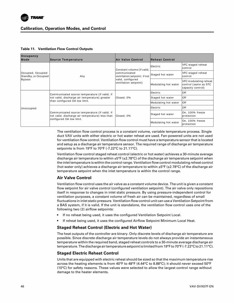
Calibration, Operation Modes, and Control
Table 11. Ventilation Flow Control Outputs
OccupancyMode Source Temperature Air Valve Control Reheat Control
Occupied, Occupied Standby, or Occupied Bypass
Any
Constant volume (if valid, communicated ventilation setpoint; if not valid, configured ventilation setpoint)
Electric VFC staged reheat control
Staged hot water VFC staged reheat control
Modulating hot waterVFC modulating reheat control (same as STC capacity control)
Unoccupied
Communicated source temperature (if valid; if not valid, discharge air temperature) greater than configured OA low limit.
Closed, 0%
Electric Off
Staged hot water Off
Modulating hot water Off
Communicated source temperature (if valid; if not valid, discharge air temperature) less than configured OA low limit.
Closed, 0%
Electric Off
Staged hot water On, 100% freeze protection
Modulating hot water On, 100% freeze protection
The ventilation flow control process is a constant volume, variable temperature process. Single duct VAV units with either electric or hot water reheat are used. Fan-powered units are not used for ventilation flow control. Ventilation flow control must have a temperature sensor that is located and setup as a discharge air temperature sensor. The required range of discharge air temperature setpoints is from 19°F to 70°F (-7.22°C to 21.11°C).
Ventilation flow control staged reheat control (electric or hot water) achieves a 30-minute average discharge air temperature to within ±5°F (±2.78°C) of the discharge air temperature setpoint when the inlet temperature is within the control range. Ventilation flow control modulating reheat control (hot water only) achieves a discharge air temperature to within ±5°F (±2.78°C) of the discharge air temperature setpoint when the inlet temperature is within the control range.
Air Valve Control
Ventilation flow control uses the air valve as a constant volume device. The unit is given a constant flow setpoint for air valve control (configured ventilation setpoint). The air valve only repositions itself in response to changes in inlet static pressure. By using pressure-independent control for ventilation purposes, a constant volume of fresh air can be maintained, regardless of small fluctuations in inlet static pressure. Ventilation flow control unit can use a Ventilation Setpoint from a BAS system, if it is valid. If the unit is standalone, the ventilation flow control uses one of the following two (2) airflow setpoints:
• If no reheat being used, it uses the configured Ventilation Setpoint Local.
• If reheat being used, it uses the configured Airflow Setpoint Minimum Local Heat.
Staged Reheat Control (Electric and Hot Water)
The heat outputs of the controller are binary. Only discrete levels of discharge air temperature are possible. Since discrete discharge air temperature levels do not always provide an instantaneous temperature within the required band, staged reheat controls to a 30-minute average discharge air temperature. The discharge air temperature setpoint is limited from 19°F to 70°F (-7.22°C to 21.11°C).
Staged Electric Reheat Control
Units that are equipped with electric reheat should be sized so that the maximum temperature rise across the heating elements is from 40°F to 48°F (4.44°C to 8.88°C); it should never exceed 50°F (10°C) for safety reasons. These values were selected to allow the largest control range without damage to the heater elements.
46 VAV-SVX07F-EN
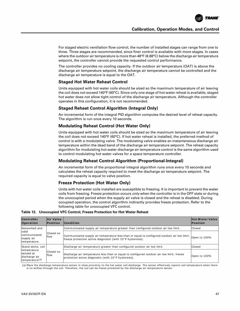
Calibration, Operation Modes, and Control
For staged electric ventilation flow control, the number of installed stages can range from one to three. Three stages are recommended, since finer control is available with more stages. In cases where the outdoor air temperature is more than 48°F (8.88°C) below the discharge air temperature setpoint, the controller cannot provide the requested control performance.
The controller provides no cooling capacity. If the outdoor air temperature (OAT) is above the discharge air temperature setpoint, the discharge air temperature cannot be controlled and the discharge air temperature is equal to the OAT.
Staged Hot Water Reheat Control
Units equipped with hot water coils should be sized so the maximum temperature of air leaving the coil does not exceed 140°F (60°C). Since only one stage of hot water reheat is available, staged hot water does not allow tight control of the discharge air temperature. Although the controller operates in this configuration, it is not recommended.
Staged Reheat Control Algorithm (Integral Only)
An incremental form of the integral PID algorithm computes the desired level of reheat capacity. The algorithm is run once every 10 seconds.
Modulating Reheat Control (Hot Water Only)
Units equipped with hot water coils should be sized so the maximum temperature of air leaving the coil does not exceed 140°F (60°C). If hot water reheat is installed, the preferred method of control is with a modulating valve. The modulating valve enables an instantaneous discharge air temperature within the dead band of the discharge air temperature setpoint. The reheat capacity algorithm for modulating hot water discharge air temperature control is the same algorithm used to control modulating hot water valves for a space temperature controller.
Modulating Reheat Control Algorithm (Proportional-Integral)
An incremental form of the proportional integral algorithm runs once every 10 seconds and calculates the reheat capacity required to meet the discharge air temperature setpoint. The required capacity is equal to valve position.
Freeze Protection (Hot Water Only)
Units with hot water coils installed are susceptible to freezing. It is important to prevent the water coils from freezing. Freeze protection occurs only when the controller is in the OFF state or during the unoccupied period when the supply air valve is closed and the reheat is disabled. During occupied operation, the control algorithm indirectly provides freeze protection. Refer to the following table for unoccupied VFC control.
Table 12. Unoccupied VFC Control, Freeze Protection for Hot Water Reheat
Controller Operation
Air Valve Position Condition
Hot Water Valve Position
Networked and valid communicated supply air temperature
Closed no flow
Communicated supply air temperature greater than configured outdoor air low limit. Closed
Communicated supply air temperature less than or equal to configured outdoor air low limit, freeze protection active diagnostic (with 10°F hysteresis). Open to 100%
Stand-alone, coil temperature sensed at discharge air temperature(a)
(a) Place the discharge temperature sensor in close proximity to the hot water coil discharge. The sensor effectively reports coil temperature when there is no airflow through the coil. Therefore, the coil can be freeze protected by the discharge air temperature sensor.
Closed no flow
Discharge air temperature greater than configured outdoor air low limit. Closed
Discharge air temperature less than or equal to configured outdoor air low limit, freeze protection active diagnostic (with 10°F hysteresis). Open to 100%
VAV-SVX07F-EN 47

Calibration, Operation Modes, and Control
Stand-alone Controller Freeze Protection
Controllers operating without communications do not have the source temperature available to them. In these cases, the discharge air temperature sensor is assumed to provide a reasonable representation of the coil temperature at conditions with no airflow, if the sensor is close to the coil. If the discharge air temperature (at no airflow) falls below the configured outdoor air low limit, the hot water valve is fully opened. The hot water valve remains OPEN until the discharge air temperature is 10°F above the configured outdoor air low limit or occupied operation begins. If the communicated source temperature is invalid and the local discharge air temperature sensor has failed, freeze protection is active and the water valve is open.
Unoccupied Ventilation Flow Control
The controller closes the air valve and the local electric heat and hot water heat are disabled. The hot water valves OPEN, if needed for freeze protection. The operation of freeze protection for local hot water heat depends on whether the controller is operating as a network controller or a stand-alone controller.
Flow Tracking (FTC)
Two (2) UC400 controllers work together to provide flow tracking control (refer to the illustration below). The space temperature controller (STC) Discharge Air Flow is communicated to the flow tracking controller and is reported as Air Flow Setpoint BAS.
Note: This must be set up on the Tracer SC using either a global reference or TGP2 program. for more details, refer to the Air Systems for Tracer SC Application Guide (BAS-APG007).
The flow tracking controller adds the configured airflow tracking offset (positive or negative) to the Air Flow Setpoint BAS and controls the airflow to this setpoint (Air Flow Setpoint Active). The flow tracking controller does not require a space temperature sensor or a discharge air temperature sensor. If the calculated airflow setpoint is less than 10% of the configured nominal airflow, and the configured airflow tracking offset is less than zero, the air valve is closed. If the calculated airflow setpoint is less than 10% of the configured nominal airflow, and the configured airflow tracking offset is greater than or equal to zero, the air valve is positioned at the configured minimum airflow. The maximum airflow setpoint is limited by the configured maximum airflow.Figure 7. Using Two UC400 Controllers to Provide Flow Tracking Control
B
A
C
BB
AA
CC
Exhaust
Comm Link
Supply STC VAV
To Other VAVs or Main Control Panel
Primary Air From Main AHU
Occupied Space
Exhaust FTC VAV
48 VAV-SVX07F-EN
Calibration, Operation Modes, and Control
Reheat Control in Flow Tracking Control Operation
Reheat is not an option on a flow tracking controller.
Unoccupied Flow Tracking Control
In unoccupied control mode, the controller operates the air valve the same as it does in occupied control mode. The controller enters this mode from a communicated command or from a local occupancy sensor.
VAV-SVX07F-EN 49
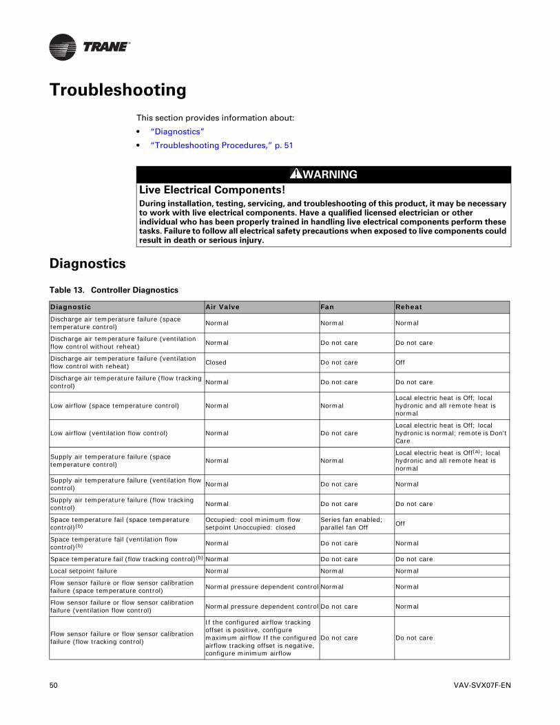
Troubleshooting
This section provides information about:
• “Diagnostics”
• “Troubleshooting Procedures,” p. 51
WARNING
Live Electrical Components!
During installation, testing, servicing, and troubleshooting of this product, it may be necessary to work with live electrical components. Have a qualified licensed electrician or other individual who has been properly trained in handling live electrical components perform these tasks. Failure to follow all electrical safety precautions when exposed to live components could result in death or serious injury.
Diagnostics
Table 13. Controller Diagnostics
Diagnostic Air Valve Fan Reheat
Discharge air temperature failure (space temperature control) Normal Normal Normal
Discharge air temperature failure (ventilation flow control without reheat) Normal Do not care Do not care
Discharge air temperature failure (ventilation flow control with reheat) Closed Do not care Off
Discharge air temperature failure (flow tracking control) Normal Do not care Do not care
Low airflow (space temperature control) Normal NormalLocal electric heat is Off; local hydronic and all remote heat is normal
Low airflow (ventilation flow control) Normal Do not careLocal electric heat is Off; local hydronic is normal; remote is Don't Care
Supply air temperature failure (space temperature control) Normal Normal
Local electric heat is Off(a); local hydronic and all remote heat is normal
Supply air temperature failure (ventilation flow control) Normal Do not care Normal
Supply air temperature failure (flow tracking control) Normal Do not care Do not care
Space temperature fail (space temperature control)(b)
Occupied: cool minimum flow setpoint Unoccupied: closed
Series fan enabled;parallel fan Off Off
Space temperature fail (ventilation flow control)(b) Normal Do not care Normal
Space temperature fail (flow tracking control)(b) Normal Do not care Do not care
Local setpoint failure Normal Normal Normal
Flow sensor failure or flow sensor calibration failure (space temperature control) Normal pressure dependent control Normal Normal
Flow sensor failure or flow sensor calibration failure (ventilation flow control) Normal pressure dependent control Do not care Normal
Flow sensor failure or flow sensor calibration failure (flow tracking control)
If the configured airflow tracking offset is positive, configure maximum airflow If the configured airflow tracking offset is negative, configure minimum airflow
Do not care Do not care
50 VAV-SVX07F-EN

Troubleshooting
Troubleshooting Procedures
UC400 Controller Failure
WARNING
Live Electrical Components!
During installation, testing, servicing and troubleshooting of this product, it may be necessary to work with live electrical components. Have a qualified licensed electrician or other individual who has been properly trained in handling live electrical components perform these tasks. Failure to follow all electrical safety precautions when exposed to live electrical components could result in death or serious injury.
In the event the UC400 controller fails, check the following:
• Check for incorrect supply voltage or no voltage. Verify that UC400 is properly grounded through one leg of transformer or with jumper to ground.
– Check Marquee LED for the following:
– Displays solid green when the UC400 controller is powered and operating normally.
– Displays solid red when the UC400 controller is powered, but represents low power or a malfunction.
– If marquee LED displays solid red, check incoming power. Measure the power input to the UC400 controller on XFMR 24 Vac input and .
The supply voltage should be between 20.4 to 27.6 Vac (24 Vac cataloged). However, voltages at either extreme may result in system instability.
– If no voltage, check up stream of controller to see were voltage has been interrupted. Refer to the section, “Appendix: Typical Trane Factory Wiring Diagrams,” p. 68.
• Check for short.
– Remove all wires from controller except incoming power.
– Check device using Tracer TU service tool to see if the UC400 controller is operating properly. If it does operate properly check, inputs/outputs for a short.
– If controller still fails, replace controller.
Note: For Instructions on how to use Tracer TU, refer to the Tracer TU Online Help and to the Tracer TU Service Tool Getting Started Guide (TTU-SVN02).
• Check for alarms or diagnostics with Tracer TU service tool.
Freeze protection active (ventilation flow control) Closed Off Off
Thumbwheel in * position (single star position) Minimum airflow Normal Normal
Thumbwheel in ** position (double star position) Maximum airflow Normal Normal
Normal Normal Normal Normal
(a) If system mode is heat or auto with a warm or hot supply air temperature(b) When a temperature sensor fails after being valid, the controller generates a diagnostic to indicate the sensor loss condition. The controller automatically
clears the diagnostic once a valid sensor temperature value is present (non-latching diagnostic).
Table 13. Controller Diagnostics (continued)
Diagnostic Air Valve Fan Reheat
VAV-SVX07F-EN 51

Troubleshooting
UC400 Controller Communication Loss
WARNING
Live Electrical Components!
During installation, testing, servicing and troubleshooting of this product, it may be necessary to work with live electrical components. Have a qualified licensed electrician or other individual who has been properly trained in handling live electrical components perform these tasks. Failure to follow all electrical safety precautions when exposed to live electrical components could result in death or serious injury.
In the event of communication loss (no activity on the LINK or IMC LEDs), check the following:
• The TX LED blinks green at the data transfer rate when the UC400 controller transfers data to other devices on the link.
• The RX LED blinks yellow at the data transfer rate when the UC400 controller receives data from other devices on the link.
• Check for incorrect supply voltage/no voltage.
– Check Marquee LED for the following:
– Displays solid green when the UC400 controller is powered and operating normally.
– Displays solid red when the UC400 controller is powered, but represents low power or a malfunction.
– If marquee LED is solid red, check incoming power. Measure the power input to UC400 controller on XFMR 24 Vac input and .
The supply voltage should be between 20.4 to 27.6 Vac (24 Vac cataloged). However, voltages at either extreme may result in system instability.
– If no voltage, check up stream of controller to see were voltage has been interrupted. Refer to the section, “Appendix: Typical Trane Factory Wiring Diagrams,” p. 68.
– Check for correct addressing on the UC400 controller.
Each UC400 controller on the BACnet link must have a unique rotary switch setting, otherwise communication problems will occur. There are three rotary switches on the front of the UC400 controller. Use these switches to define a three-digit address when the UC400 controller is installed in a BACnet system (for example, 107, 120, and so on), whether with other Trane BACnet controls or controls from another vendor. This three-digit rotary switch setting is used as both the BACnet MAC address and the BACnet Device ID.
Note: Valid addresses are 001 to 120. Sequential addressing without gaps is recommended.
– Verify that there are no duplicated addresses on the communication link.
• Check for alarms or diagnostics with Tracer TU service tool, and check that the communication link avoids interference. Communication link should not be routed near or with any voltage source.
– The following wiring best practices are recommended:
– Strip no more than 2 inches (5 cm) of the outer conductor of shielded wire.
– Avoid sharing 24 Vac power between unit controllers.
– Ensure that 24 Vac power supplies are consistently grounded. If grounds are not maintained, then intermittent or failed communication could result.
• Check that twisted shielded pair wiring is used and observe the following guidelines (refer to the section, “Wiring Installation,” p. 14):
52 VAV-SVX07F-EN
Troubleshooting
– Connect the shield portion of the wire at the first unit controller in the link.
– Tape back the shield at the end of the unit controller line.
– Wire together and tape all other shields at each unit controller.
• Check application version and build or download the latest application version using the Tracer TU service tool.
Note: For instructions on how to use Tracer TU, refer to the Tracer TU Online Help and the Tracer TU Service Tool Getting Started Guide (TTU-SVN02).
• If communication loss persists, we recommend connecting to the link with Serial Spy MS/TP analyzer to review the token passing. For detailed instructions about use, analysis and Comm link voltage tests, refer to the BACnet MS-TP Wiring and Link Performance Best Practices and Troubleshooting Guide (BAS-SVX51).
Wired Zone Sensor Failure
WARNING
Hazardous Service Procedures!
The maintenance and troubleshooting procedures recommended in this section of the manual could result in exposure to electrical, mechanical or other potential safety hazards. Always refer to the safety warnings provided throughout this manual concerning these procedures. When possible, disconnect all electrical power including remote disconnect and discharge all energy storing devices such as capacitors before servicing. Follow proper lockout/tagout procedures to ensure the power can not be inadvertently energized. When necessary to work with live electrical components, have a qualified licensed electrician or other individual who has been trained in handling live electrical components perform these tasks. Failure to follow all of the recommended safety warnings provided, could result in death or serious injury.
In the event that the UC400 controller reports an incorrect zone temperature, check the following:
• Verify that the actual room temperature is higher or lower than what the UC400 controller reads.
• Check the location and installation of the zone sensor for heat sources or drafts. If necessary, a calibration offset can be added with Tracer TU, in the Space Temperature Local configuration screen.
Note: If the zone sensor is OFF more than ± 2 degrees, proceed to the next bullet item.
• Verify that the zone sensor is wired correctly. Refer to the section, “Wiring Installation,” p. 14.
• Verify that the zone sensor is working properly.
– Disconnect the zone sensor terminal plug from the UC400 controller and using an ohmmeter, measure the resistance across the terminals 1 and 2. Compare the resistance to the temperature (refer to Table , p. 54). The resistance value should be within ± 2 degrees near those measured with an accurate temperature measuring device. If not, replace the zone sensor.
• Verify that neither the wiring or the UC400 controller are defective. With wires still connected to the UC400 controller, disconnect zone sensor wires that were connected to terminals 1 and 2 of zone sensor. Measure for 2.6–3.0 Vdc and if it is not present, then verify whether the UC400 controller is outputting 2.6–3.0 Vdc.
To do this, disconnect the wires on the UC400 controller from terminals AI1 and , and measure the Vdc– it should be 2.6–3.0 Vdc. If 2.6–3.0 Vdc is present at the UC400 controller, the wires going to the zone are OPEN. If the correct voltage is not present, check the incoming power to the UC400 controller on XFMR 24 Vac input and . It should measure 24 Vac ± 15%.
VAV-SVX07F-EN 53

Troubleshooting
If the proper voltage is measured at the XFMR 24 Vac input and , and there is no voltage at AI1 and , replace the UC400 controller.
• Verify that the zone sensors are not shorted out. Check the resistance across the wires. Disconnect wires from the UC400 controller and zone sensor, ensuring that the ends are not touching each other, and then measure resistance. It should be infinite or no conductivity. If lower resistance is shown, then the wires are shorted together and need to be replaced.
Table 14. Zone Sensor Temperature Resistance.
Temperature (oF)Thermostat Thumbwheel
Resistance (Ohms)(a)
(a) Thumbwheel resistance checks are made at terminal 2 and 3 on the zone sensor. Temperature sensor resistance is measured at terminal 1 and 2 of the zone sensor.
5556575859
792772753733714
17.016.516.115.715.4
6061626364
694675656636617
15.014.614.314.013.6
6566676869
597578558539519
13.313.012.612.312.1
7071727374
500481461442422
11.811.511.211.010.7
7576777879
403383364344325
10.410.210.09.79.5
808182838485
306286267247228208
9.39.08.88.68.48.2
Sensor Resistance (k Ohms)
54 VAV-SVX07F-EN

Troubleshooting
Wired Zone Sensor Setpoint Failure
WARNING
Hazardous Service Procedures!
The maintenance and troubleshooting procedures recommended in this section of the manual could result in exposure to electrical, mechanical or other potential safety hazards. Always refer to the safety warnings provided throughout this manual concerning these procedures. When possible, disconnect all electrical power including remote disconnect and discharge all energy storing devices such as capacitors before servicing. Follow proper lockout/tagout procedures to ensure the power can not be inadvertently energized. When necessary to work with live electrical components, have a qualified licensed electrician or other individual who has been trained in handling live electrical components perform these tasks. Failure to follow all of the recommended safety warnings provided, could result in death or serious injury.
In the event that the UC400 controller reports an incorrect zone setpoint, check the following:
• Verify that the zone sensor is wired correctly.
• Check that the zone sensor setpoint dial is not defective.
– Disconnect the zone sensor terminal plug from the UC400 controller and using an ohmmeter, measure the resistance across the terminals 2 (common) and 3 (setpoint). Compare the resistance to specified setpoint on sensor using Table , p. 54. The resistance shown should correlate within ± 2 degrees of setpoint. If not, replace the zone sensor.
• Check the wiring and the UC400 controller.
– With the wires still connected to UC400 controller, disconnect zone sensor setpoint wires and check voltage (direct current) from wires that were connected to terminals 2 and 3 of zone sensor. Measure for 2.6–3.0 Vdc and if not present, then verify whether the UC400 controller is outputting 2.6–3.0 Vdc.
To do this, disconnect the wires on the UC400 controller on terminals Ground and AI2 and measure the Vdc– it should be 2.6–3.0 Vdc. If there is 2.6–3.0 Vdc at the UC400 controller, the wires going to the zone are OPEN. If 2.6–3.0 Vdc is not present, check the incoming power to the UC400 controller on XFMR 24 Vac input and . It should measure 24 Vac ± 15%. If the proper voltage is measured at the XFMR 24 Vac input and , and there is no voltage at the and AI2, replace the UC400 controller.
• Verify that the zone sensor setpoint is not shorted out.
– Check the resistance across the wires. Disconnect wires from the UC400 controller and zone sensor making sure the ends are not touching each other and measure resistance. It should be infinity or no conductivity. If lower resistance is shown, then the wires are shorted together and need replacing.
VAV-SVX07F-EN 55
Troubleshooting
Airflow Sensor Failure
In the event that the air valve is reading position (pressure dependent) instead of flow (pressure independent), or in the event that the measured flow reads incorrectly, (for example, different from the balance report), check the following:
• Recalibrate the VAV unit by cycling power to unit. This can also be accomplished with Tracer TU service tool or Tracer SC.
Important:� Cycling power to the VAV board: The default will automatically cause the unit to calibrate, but this depends on binary value, auto-calibrate, enable/disable point. However, following the procedure outlined below will provide a more accurate calibration. It is only necessary to perform this procedure when experiencing incorrect flow readings or if the unit reverts to pressure dependent mode despite being above 5% and below 110% of cataloged flow and performing a normal calibration and does not correct the problem.
To calibrate:
c. Connect to the UC400 controller with Tracer TU service tool.
d. Turn the central air handler OFF. If this is not possible, Trane recommends pulling the transducer tubes off during the calibration process to simulate this.
e. Select the Zero Air and Water Valve Start button on the Commissioning page. Tracer TU service tool will indicate that calibration is taking place. When calibration is complete, the box will release to AUTO.
f. Drive the box OPEN by overriding multi-state value 2, air flow override, to Air Valve Maximum Setpoint, from the Multi-state Status page to ensure that the box is not below 5% of its cataloged CFM. The controller is accurate in reading flow from 5% to 110% of cataloged CFM.
g. Release the box to AUTO and perform any necessary balancing work. For details, refer to the Tracer TU Online Help.
h. Check to see if flow has been established. If flow is not established, or inaccurate, proceed to the following bullet.
• If the tubing or flow ring is OFF, reversed, plugged, or has a leak:
a. Check with a magnahelic gauge and compare with the delta pressure (DP) chart located on the VAV box. (See Figure 8, p. 57.)
Note: The chart shown in Figure 8 is intended for Trane F-Style boxes. Other manufacturers may have different delta pressure charts.
b. Check the tubing for reversal and/or leaks.
c. Check the flow ring for plugged holes. Blow out with compressed air if necessary.
56 VAV-SVX07F-EN

Troubleshooting
Figure 8. Delta Pressure Chart for Trane F-Style Boxes
00..0011
0.0.11
11
55
000000,,0011000000,,110000110011CC ffmm
Flow
Flow
SSeennss
oorrDD
PP((IInn
. .wwgg
))
• Wrong unit size downloaded into the UC400 controller setup screen. Verify that the actual unit size matches what is listed on the unit nameplate.
• Poor inlet configuration.
– Trane recommends 1½-duct diameters of straight duct before the inlet of the box (a 12-inch box should have 18 inches of straight run duct before the inlet).
• To determine whether or not the transducer has failed, check the following:
– Check the 24 volts AC supply at XFMR 24 Vac input and on the r UC400 controller. Voltage should be between 20.4 and 27.6 Vac.
– Read the input voltage to the transducer from the UC400 controller between the green and red wires on P1 of the controller. The voltage should be between 4.50 volts DC and 5.50 volts DC (5 volts DC cataloged). If voltage not available, replace the UC400 controller.
– Remove the high and low tubes from the transducer (to simulate no flow). Read the transducer output voltage on P1 of the UC400 controller between the green and the black wires with a voltmeter. The voltage should be between 0.20 volts DC and 0.30 volts DC (0.25 volts DC is the null voltage output of the transducer indicating zero flow). If voltage not available, replace the transducer.
Note: The formula for the transducer output voltage is 0.25 + 0.75 * <delta P>, where delta P is the pressure in inches of water column. Delta P can range from 0 to 5 inches of W.C.
• With flow going across the flow ring, measure the differential pressure with a magnahelic and use the transducer output voltage formula to check accuracy of reported value. Read the transducer output voltage between the green and the black wires. The measured value should correspond to the value given in the transducer output formula. If transducer is off by ± 5%, replace transducer.
VAV-SVX07F-EN 57
Troubleshooting
Supply/Discharge Air Temperature Sensor Failure
WARNING
Hazardous Service Procedures!
The maintenance and troubleshooting procedures recommended in this section of the manual could result in exposure to electrical, mechanical or other potential safety hazards. Always refer to the safety warnings provided throughout this manual concerning these procedures. When possible, disconnect all electrical power including remote disconnect and discharge all energy storing devices such as capacitors before servicing. Follow proper lockout/tagout procedures to ensure the power can not be inadvertently energized. When necessary to work with live electrical components, have a qualified licensed electrician or other individual who has been trained in handling live electrical components perform these tasks. Failure to follow all of the recommended safety warnings provided, could result in death or serious injury.
In the event that the UC400 controller reports an incorrect or failed discharge or supply air temperature, check the following:
• Ensure the UC400 controller has been configured for the input and the point has not been placed out of service.
• Discharge or supply air temperature is higher or lower than what the UC400 controller reads.
• Check the location and installation of the sensor. Change the calibration factor in the UC400 controller setup screens.
Note: If sensor is off more than ± 2 degrees continue to the next bullet.
• Check sensor wiring for the correct connections.
• Defective sensor.
– Disconnect the sensor terminal plug from the UC400 controller and using an ohmmeter, measure the resistance across the sensor wires. Compare the resistance to temperature (refer to Table , p. 54). The resistance measured should correspond to a temperature within ± 2 degrees near those measured with an accurate temperature measuring device. If the measured resistance does not correspond, replace the sensor.
• Defective wiring or defective UC400 controller.
– Verify that the UC400 controller is outputting 2.6–3.0 Vdc. This can be performed by
disconnecting the wires on the UC400 controller on terminals AI4 and for a discharge air
temperature sensor, or AI5 and for a supply air temperature sensor, and measuring the
Vdc. It should be 5 Vdc. If there is 2.6–3.0 Vdc at the UC400 controller, the wires going to the
zone are OPEN. If 5 Vdc is not present, check the incoming power to the UC400 controller
on XFMR 24 Vac input and . It should measure 24 Vac ± 15%. If the proper voltage is
measured at XFMR 24 Vac input , and there is no voltage at AI4 and for discharge air
temperature sensor or AI5 and for supply air temperature sensor, replace the UC400
controller.
58 VAV-SVX07F-EN

Troubleshooting
CO2 Sensor Failure
WARNING
Hazardous Service Procedures!
The maintenance and troubleshooting procedures recommended in this section of the manual could result in exposure to electrical, mechanical or other potential safety hazards. Always refer to the safety warnings provided throughout this manual concerning these procedures. When possible, disconnect all electrical power including remote disconnect and discharge all energy storing devices such as capacitors before servicing. Follow proper lockout/tagout procedures to ensure the power can not be inadvertently energized. When necessary to work with live electrical components, have a qualified licensed electrician or other individual who has been trained in handling live electrical components perform these tasks. Failure to follow all of the recommended safety warnings provided, could result in death or serious injury.
In the event that the UC400 controller reports an incorrect or failed CO2 sensor input temperature, check the following:
• Check that the CO2 point is not out of service.
Jumper Positions
• Check jumper position on CO2 sensor.
– UC400 default is 4–20 mA.
Note: If the CO2 sensor is not set up for 4 –20 mA, the CO2 input can be put out of service with Tracer TU, changed to the 0–20 mA or 0–10 Vdc in the configuration screen, and then put back in service.
– Check voltage between UI2 and with the sensor connected. It should be between 1-10V DC. If it is not, check incoming power.
– Check voltage input to CO2 sensor with voltmeter. It should be between 20.4 to 27.6 Vac; nominal is 24 Vac.
• After measuring the proper voltage at incoming power, and there is no VDC output at UI2 and , replace sensor. If there is no voltage, check up stream of controller to see were voltage has
been interrupted. Refer to the section, “Appendix: Typical Trane Factory Wiring Diagrams,” p. 68.
VAV-SVX07F-EN 59
Troubleshooting
VAV Damper Failure
WARNING
Hazardous Service Procedures!
The maintenance and troubleshooting procedures recommended in this section of the manual could result in exposure to electrical, mechanical or other potential safety hazards. Always refer to the safety warnings provided throughout this manual concerning these procedures. When possible, disconnect all electrical power including remote disconnect and discharge all energy storing devices such as capacitors before servicing. Follow proper lockout/tagout procedures to ensure the power can not be inadvertently energized. When necessary to work with live electrical components, have a qualified licensed electrician or other individual who has been trained in handling live electrical components perform these tasks. Failure to follow all of the recommended safety warnings provided, could result in death or serious injury.
In the event that the air valve does not modulate, check the following:
• Tracer SC or Tracer TU service tool has enabled an override function in the UC400. Verify no overrides are present by clicking on the override icon of multi-state value 2, Air Flow Override, on the TU Multi-state Status page.
– The overrides are Open, Closed, Min, or Max. Release all overrides.
– The UC400 controller is going through a recalibrate (reset) command. This is shown in the diagnostic list in Tracer TU service tool.
– Wait for calibration to finish.
• Zone temperature is greater than the heat setpoint or less than the cool setpoint. Change the heat and/or cool setpoint.
• Actuator not driving full drive time.
– Drive time on TU Setup Parameters page, Stroke Times group, not set at 90 seconds on current Varitrane units.
– Adjust to correct damper travel time using Tracer TU service tool.
– Damper actuator loose on shaft.
– Tighten damper actuator set screw to damper shaft by first rotating damper fully clockwise until closed, releasing actuator clutch and rotating actuator collar fully clockwise, and then tightening the setscrews. Incorrect adjustment can result in broken stub axle adapters.
– Measure the power input to XFMR 24 Vac input and on the UC400 controller. The supply voltage should be between 20.4 to 27.6 Vac (24 Vac nominal). However, voltages at either extreme may result in system instability and cause damper to not be driven its full range.
– If no voltage, check up stream of controller to see were voltage has been interrupted. Refer to the section, “Appendix: Typical Trane Factory Wiring Diagrams,” p. 68.
• Actuator motor has failed.
– Check voltage at the TRIAC supply B to common , which should be 24 Vac. If 24 Vac is not present, check the incoming power to the UC400 controller on XFMR 24 Vac input and TRIAC supply. The voltage should measure 24 Vac, ± 15%. After measuring for the proper voltage at XFMR 24 Vac input and , and there is no voltage at the TRIAC B output and common , check the wiring between the UC400 24Vac transformer supply terminals and the TRIAC supply terminals.
– Check damper actuator motor by applying 24 Vac directly to common (blue) and jumper open (black) wire to ground to drive damper open. Damper should drive open. If not, replace damper actuator.
60 VAV-SVX07F-EN
Troubleshooting
– Check damper actuator motor by applying 24 Vac directly to common (blue) and jumper closed (red) wire to ground to drive damper closed. Damper should drive closed. If not, replace damper actuator.
– The UC400 controller outputs are switched to ground via low-side triac solid-state switches. Because the binary outputs are triac based, the state of the output is difficult to check directly with a digital multi-meter (DMM). To check state of the output with a DMM, the output must me loaded with a 12VA max load. For example, a fan relay. TRIACs can be checked by purchasing a 24 Vac LED and connecting to the TRIAC output. If the 24 Vac LED does not light up, replace the UC400 controller.
Important:� Do not jumper 24 Vac to BO8 and BO9 because damage will occur to the UC400 binary output circuitry.
VAV Series Fan Failure
WARNING
Hazardous Service Procedures!
The maintenance and troubleshooting procedures recommended in this section of the manual could result in exposure to electrical, mechanical or other potential safety hazards. Always refer to the safety warnings provided throughout this manual concerning these procedures. When possible, disconnect all electrical power including remote disconnect and discharge all energy storing devices such as capacitors before servicing. Follow proper lockout/tagout procedures to ensure the power can not be inadvertently energized. When necessary to work with live electrical components, have a qualified licensed electrician or other individual who has been trained in handling live electrical components perform these tasks. Failure to follow all of the recommended safety warnings provided, could result in death or serious injury.
In the event that the fan output does not energize, check the following:
• Verify the output configuration in the UC400 controller setup screen. Unit needs to be configured as series fan.
• Outputs on the UC400 controller are configured as normally closed. Verify the output configuration in the UC400 controller setup screen.
Note: Series fan-powered units in the occupied mode have the fan continuously energized.
• Tracer SC has the fan output disabled. Check overrides to ensure they are not inhibiting fan operation.
• A flow override exists locking out the fan output. Ensure that either Tracer SC or the Tracer TU service tool has released fan disable override.
• If the UC400 controller is calling for the fan to be ON (viewed in the Status screen), and if it is not, then check the TRIAC output wiring and relay output.
– Override damper open.
– Verify that the fan cycles ON.
– Check BO4 to common . It should have 24 Vac. If it does not, measure the power input to on XFMR 24 Vac input and of the UC400 controller. The supply voltage should be between 20.4 to 27.6 Vac (24 Vac cataloged). However, voltages at either extreme may result in system instability.
– TRIACs can be checked by purchasing a 24 Vac LED and connecting to the TRIAC output. If the 24 Vac LED does not light up, replace the UC400 controller.
– Remove fan wires from the UC400 controller and apply 24 Vac directly to fan relay wires.
– Fan relay should energize. If it does not energize, check wiring. If wiring is correct, replace fan relay.
VAV-SVX07F-EN 61

Troubleshooting
NOTICE:
Equipment Damage!
The UC400 controller outputs are switched to ground. Do not jumper 24 Vac to binary output TRIAC(s) because damage will occur.
• After all checks have been completed, check motor fan winding integrity and bearing failure.
VAV Parallel Fan Failure
WARNING
Hazardous Service Procedures!
The maintenance and troubleshooting procedures recommended in this section of the manual could result in exposure to electrical, mechanical or other potential safety hazards. Always refer to the safety warnings provided throughout this manual concerning these procedures. When possible, disconnect all electrical power including remote disconnect and discharge all energy storing devices such as capacitors before servicing. Follow proper lockout/tagout procedures to ensure the power can not be inadvertently energized. When necessary to work with live electrical components, have a qualified licensed electrician or other individual who has been trained in handling live electrical components perform these tasks. Failure to follow all of the recommended safety warnings provided, could result in death or serious injury.
In the event that the fan output does not energize, check the following:
• Verify the output configuration in the UC400 controller setup screen. Unit needs to be configured as parallel fan.
• Outputs on the UC400 controller are configured as normally closed. Verify the output configuration in the UC400 controller setup screen.
Note: Parallel fan can be enabled by either a differential temperature above the heating setpoint or CFM flow.
• Tracer SC has the fan output disabled. Ensure that the overrides are not inhibiting fan operation.
Note: For ECM fan there are two controlling outputs. The start/stop binary output and Analog fan speed. If the fan speed is at 0% then the fan should be running at minimum flow The status of the outputs can be checked on the TU binary status page.
• A flow override exists locking out the fan output. Ensure that either Tracer SC or the Tracer TU has released fan disable override. Flow overrides can be checked on the TU multi-state status page.
Note: If fan cycling is based on temperature or airflow, proceed to the next two bullet items.
• If fan cycling is based on temperature and zone temperature is at or above the heating setpoint plus heating offset on units configured as temperature control. A set differential of 0.5°F exists to prevent short cycling.
– Increase the UC400 controller heating setpoint causing fan to cycle ON.
– Lower the heating setpoint by 6 degrees and the fan will cycle OFF.
• If the fan cycling is based on airflow, the unit fan is energized whenever supply airflow is below this setpoint. For this parallel fan configuration, the fan control point (if specified in a percentage of unit airflow), must be set between 15% and 30% of the units cataloged airflow to assure proper operation. A differential of 5% exists to avoid excessive fan cycling.
– Override damper closed until CFM is below enabled flow setpoint.
– Verify that the fan cycles ON.
62 VAV-SVX07F-EN

Troubleshooting
– Override damper open until CFM is above enabled flow setpoint fan will cycle OFF.
• If the UC400 controller is calling for the fan to be ON (viewed in the Status screen), and it is not, then check the TRIAC output wiring and relay output
– Check BO4 to common . It should have 24 Vac. If it does not, measure the power input to on XFMR 24 Vac input and of the UC400 controller. The supply voltage should be between 20.4 and 27.6 Vac (24 Vac cataloged). However, voltages at either extreme may result in system instability.
– TRIACs can be checked by purchasing a 24 Vac LED. Connect LED wires to triac outputs on controller. Raise setpoint to initiate call for heat. If the UC400 BO LEDs are lit, but the test LED does not, replace the controller.
Note: Measuring the output voltage with a meter is not a reliable test for TRIAC output voltage. The TRIAC output requires a small amount of current draw in order to fully switch 24 Vac to ground. The LED provides the required current draw.
– Remove fan wires from the UC400 controller and apply 24 Vac directly to fan relay wires.
– Fan relay should energize. If it does not energize, check wiring. If the wiring check is good, replace fan relay.
NOTICE:
Equipment Damage!
The UC400 controller outputs are switched to ground. Do not jumper 24 Vac to binary output TRIAC(s) because damage will occur.
• After all checks have been completed, check motor fan winding integrity and bearing failure.
PSC (Permanent Split Capacitor) Variable Speed Motor Check
WARNING
Live Electrical Components!
During installation, testing, servicing and troubleshooting of this product, it may be necessary to work with live electrical components. Have a qualified licensed electrician or other individual who has been properly trained in handling live electrical components perform these tasks. Failure to follow all electrical safety precautions when exposed to live electrical components could result in death or serious injury.
If the PSC Variable speed motor control does not change the motor speed, check the following:
• Wires connected improperly. Refer to the section, “Appendix: Typical Trane Factory Wiring Diagrams,” p. 68.
• Check voltage selection switch on side of variable speed motor control. It should be set for motor voltage.
• Check speed control by:
– Turning the voltage selection switch fully counterclockwise.
– Turning the motor speed control potentiometer fully counterclockwise.
– Ensuring the motor remains OFF.
• Turn voltage selection switch fully clockwise, but:
– The motor speed control potentiometer still remains fully counterclockwise.
– Measure the motor voltage. It should be no more than 8 Vac lower than line voltage.
– The voltage selection switch still remains fully clockwise.
VAV-SVX07F-EN 63

Troubleshooting
• Turn motor speed control potentiometer slowly, fully clockwise. The motor should smoothly ramp to full speed.
• If the PSC motor speed controller fails, replace it.
VAV Electric Heat Stage Failure
WARNING
Live Electrical Components!
During installation, testing, servicing and troubleshooting of this product, it may be necessary to work with live electrical components. Have a qualified licensed electrician or other individual who has been properly trained in handling live electrical components perform these tasks. Failure to follow all electrical safety precautions when exposed to live electrical components could result in death or serious injury.
In the event that the heat outputs do not energize, check the following:
• Zone temperature is at or above the heating setpoint. Increase the UC400 controller heating setpoint.
• Verify the output configuration in the UC400 controller setup screen. Unit needs to be configured as 3-stage electric heat.
• Tracer SC has the electric heat output disabled. Check group, global, and/or Tracer overrides to make sure they are not inhibiting heat operation.
• Minimum heating CFM is not being met, airflow is too low. Increase the airflow or lower the minimum heating flow.
• Heat relays have failed.
– If the UC400 controller is calling for electric heat (viewed in the Status screen), then the LED is ON for correct binary output(s) for the stage(s) of heat to be ON. If not, then check the UC400 controller TRIAC output, wiring connections, and relay output.
– Check correct binary output to common . It should have 24 Vac. If it does not, measure the power input to on XFMR 24 Vac input and of the UC400 controller. The supply voltage should be between 20.4 and 27.6 Vac (24 Vac cataloged). However, voltages at either extreme may result in system instability.
– Heat TRIACs can be checked by purchasing a 24 Vac LED and connecting to the TRIAC output. If the 24 Vac LED does not light up, replace the UC400 controller.
NOTICE:
Equipment Damage!
The UC400 controller outputs are switched to ground. Do not jumper 24 Vac to binary output TRIAC(s) because damage will occur.
• Move electric heat relay wires from the UC400 controller and apply 24 Vac directly.
• Electric heat stage should energize. If it does not, then check the wiring, safeties, electric heat contact, or replace any necessary components.
64 VAV-SVX07F-EN
Troubleshooting
VAV Modulating Hot Water Failure
WARNING
Live Electrical Components!
During installation, testing, servicing and troubleshooting of this product, it may be necessary to work with live electrical components. Have a qualified licensed electrician or other individual who has been properly trained in handling live electrical components perform these tasks. Failure to follow all electrical safety precautions when exposed to live electrical components could result in death or serious injury.
In the event that the heat outputs do not energize, check the following:
• Zone temperature is at or above the heating setpoint. Increase the UC400 controller heating setpoint.
• Verify the valve control type selection on the TU Equipment Configuration screen. Unit needs to be configured as modulating hot water.
• Tracer SC has the heat output disabled. Check overrides to ensure they are not inhibiting heat operation.
• Heat relays have failed.
– If the UC400 controller is calling for binary output (viewed in the Status screen), then the LED is ON for the correct binary output to open the valve. If the TRIAC is not closed, then check the UC400 controller TRIAC output, wiring connections, and relay output.
– Check for correct binary outputs. It should have 24 Vac. If it does not, measure the power input to XFMR 24 Vac input and of the UC400 controller. The supply voltage should be between 20.4 to 27.6 Vac (24 Vac cataloged). However, voltages at either extreme may result in system instability.
– Heat TRIAC(s) can be checked by purchasing a 24 Vac LED and connecting to the TRIAC output. If they are lit, it is calling heat output to be OPEN or CLOSED by the UC400 controller. If LED is not lit, replace the UC400 controller.
NOTICE:
Equipment Damage!
The UC400 controller outputs are switched to ground. Do not jumper 24 Vac to binary output TRIAC(s) because damage will occur.
VAV-SVX07F-EN 65
Troubleshooting
Trane/Honeywell Proportional Valve Check Out
There are two failures can result in over conditioning the space:
• Cartridge failure
• Actuator failure
Cartridge Failure
Cartridge failure will occur if the actuator is driven CLOSED, but there is an 1/8 inch or greater of movement in the indicator, or if the piston has not returned up past the ‘A’ port (frozen). In either case, the cartridge is not closed off completely which will result in over heating (or over cooling) the space.
Actuator Failure
Actuator failure will occur if the actuator has stopped moving to the CLOSED position when commanded to and when there is no play in the lever.
Remove the actuator and work the cartridge stem manually. If the stem moves freely, then only the actuator has failed. However, if the stem is sluggish or stuck, then both the actuator and the cartridge have failed.
Note: The actuator fault is intermittent. However, the actuator may operate again when removed from the valve or if it is tapped with a tool while still on the valve. The actuator indicator on the side of the actuator should be positioned at the top of the actuator when valve is CLOSED.
VAV 2-Position Hot Water Failure
WARNING
Live Electrical Components!
During installation, testing, servicing and troubleshooting of this product, it may be necessary to work with live electrical components. Have a qualified licensed electrician or other individual who has been properly trained in handling live electrical components perform these tasks. Failure to follow all electrical safety precautions when exposed to live electrical components could result in death or serious injury.
In the event that the heat outputs do not energize, check the following:
• Zone temperature is at or above the heating setpoint. Increase the UC400 controller heating setpoint.
• Verify the output configuration in the UC400 controller setup screen. Unit needs to be configured as proportional hot water.
• Tracer SC has the heat output disabled. Check overrides to ensure they are not inhibiting heat operation.
66 VAV-SVX07F-EN

Troubleshooting
• Heat relays have failed.
– The UC400 controller will call for the valve to be OPEN, (viewed in the Status screen). If not, check the TRIAC output, wiring connections, and relay output.
– If the UC400 controller is calling for the heat output to be ON (viewed in the Status screen), then the LED is OFF for the correct Binary Output 7 to open the valve (note, polarity is reversed on this point). If the TRIAC is not closed, then check the UC400 controller TRIAC output, wiring connections, and relay output.
– Check for correct binary outputs. It should have 24 Vac. If it does not, measure the power input to XFMR 24 Vac input and of the UC400 controller. The supply voltage should be between 20.4 to 27.6 Vac (24 Vac cataloged). However, voltages at either extreme may result in system instability.
NOTICE:
Equipment Damage!
The UC400 controller outputs are switched to ground. Do not jumper 24 Vac to binary output TRIAC(s) because damage will occur.
• Heat TRIAC(s) can be checked by purchasing a 24 Vac LED and connecting to the TRIAC output. If they are lit, it is calling heat output to be OPEN or CLOSED by the UC400 controller. If LED is not lit, replace the UC400 controller.
VAV-SVX07F-EN 67
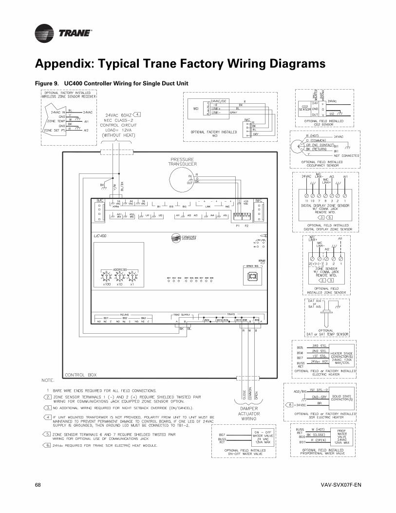
Appendix: Typical Trane Factory Wiring Diagrams
Figure 9. UC400 Controller Wiring for Single Duct Unit
68 VAV-SVX07F-EN

Appendix: Typical Trane Factory Wiring Diagrams
Figure 10. UC400 Controller Wiring for Fan Powered Unit
VAV-SVX07F-EN 69

70 VAV-SVX07F-EN
Additional Resources
• BACnet MS-TP Wiring and Link Performance Best Practices and Troubleshooting Guide(BAS-SVX51)
• Engineered Smoke Control System for Tracer SC System Controller Application Guide (BAS-APG019)
• Tracer UC400 Controller BACnet Protocol Implementation Conformance Statement (PICS) [BAS-PRG007]
• Tracer UC400 Programmable Controller Installation, Operation, and Maintenance Manual (BAS-SVX20)
• Tracer SC System Controller Installation and Setup (BAS-SVX31)
• Air Systems for Tracer SC Application Guide (BAS-APG007)
• Tracer SC Unit Controller Wiring Guide (BAS-SVN03)
• Tracer Graphical Programming 2 (TGP2) Editor Online Help
• Tracer Graphical Programming (TGP2) Application Guide (BAS-APG008)
• Tracer TU Online Help
• Tracer TU Service Tool Getting Started Guide (TTU-SVN01)
• Wireless Zone Sensors for Models WTS, WZS, and WDS Installation, Operation and Maintenance Manual (BAS-SVX04)
Note: Wireless zone sensors are compatible with the Tracer Programmable BACnet Controller and can be ordered as factory installed.

©2020 Trane
Trane has a policy of continuous product and product data improvement and reserves the right to change design and specifications without notice. We are committed to using environmentally conscious print practices.
Trane - by Trane Technologies (NYSE: TT), a global climate innovator - creates comfortable, energy efficient indoor environments for commercial and residential applications. For more information, please visit trane.com or tranetechnologies.com.
VAV-SVX07F-EN 09 Apr 2020Supersedes VAV-SVX07E-EN (Mar 2016)