installation, operation and maintenance manual · tw 242 e basic-line lift electronic installation,...
TRANSCRIPT

TW 242 E
Basic-Line Lift
Electronic
INSTALLATION, OPERATION AND MAINTENANCE MANUAL
Always read the manual carefully to avoid damage or accidents through misuse.

TWIN BUSCH GmbH
Technical changes for purposes of a technical advancement as well as deviation in colour, errors and printing mistakes are reserved. page 2 of 48

TWIN BUSCH GmbH
Technical changes for purposes of a technical advancement as well as deviation in colour, errors and printing mistakes are reserved. page 3 of 48
INDEX
1. Important warnings 4 - 5
1.1 Warnings
1.2 Qualified personnel
1.3 Safety warnings
1.4 Warnings
1.5 Noise level
1.6 Training
2. General overview 6-7
2.1 General description
2.2 Technical Data
2.3 Construction plan
3. Installation instructions 8-14
3.1 Before Installing
3.1.1 Equipment
3.1.2 Check list
3.1.3 Ground requirements
3.2 Before Installation
3.3 Installation
3.4 Check list after installation
4. User instructions 14-17
4.1 Safety precautions
4.2 Control box
4.3 Assembly instructions
4.4 Instructions
4.5 Emergency lowering (Power cut)
5. Trouble shooting 18
6. Maintenance 19
7. Attachment 20-38
Attachment 1: Pack list
Attachment 2: Dimensions
Attachment 3: Floor mounting Instructions
Attachment 4: Hydraulic system
Attachment 5: Circuit diagram
Attachment 6: Lift Diagrams
Attachment 7: Spare parts, adapter for transporters
Attachment, Size and weight requirement for vehicles
Attachment, CE-Certificate and EG-declaration of conformity

TWIN BUSCH GmbH
Technical changes for purposes of a technical advancement as well as deviation in colour, errors and printing mistakes are reserved. page 4 of 48
1. Safety warnings
1.1 Important notice
The manufacturer will take no responsibility for improper installation, improper usage, overloading or non suitable ground
for mounting the lift.
This model is specially designed for lifting vehicles up to the specified weight. Usage for other purposes will not be covered
by the manufacture or the dealer for accidents or damage. (Weight distribution see diagram page 22)
Pay careful attention to the approved weights! The warning stickers on the lift show the specifications. Never attempt to lift
vehicles above the specified weight!
Always read the manual carefully to avoid damage or accidents through misuse.
(Weight, wheel base and vehicle sizes, see Diagram page 43)
1.2 Qualified personnel
1.2.1 Only qualified and trained staff should be allowed to operate the lift.
1.2.2 The electrical connections should be carried out by an electrician.
1.2.3 People or customers are not allowed in the lift and working area.
1.3 Safety warning
1.3.1 Never mount the lift on asphalt or other soft surfaces.
1.3.2 Read the safety warnings thoroughly before using the lift.
1.3.3 Never leave the control panel when the lift is in motion
1.3.4 Always keep hands and feet away from moving parts especially when lowering the lift.
1.3.5 Only qualified trained personnel are allowed to operate the lift.
1.3.6 Always ware suitable clothing
1.3.7 The lift and surrounding area should be kept clean to avoid accidents
1.3.8 The lift is designed to lift complete vehicles which do not exceed the lifting capacity. (See page 22).
1.3.9 Make sure that all safety locks are engaged before any attempt is made to work under or near the lift. Never
remove any safety related components from the lift and do not use if such parts are damaged or missing.
1.3.10 Do not rock the vehicle or cause excessive weight displacement by removal of heavy parts when working on the lift.
1.3.11 All moving parts of the lift should be regularly maintained and checked. Should any parts be damaged, work on the
lift should be stopped immediately and you should contact the service partner for advice.
1.3.12 When not in use the lift should be lowered completely to the floor and the electric turned off.
1.3.13 If the lift is not used for a longer period of time, it is recommended to:
a. Disconnect the power source.
b. Empty the oil tank.
c. Lubricate the moving parts with grease.

TWIN BUSCH GmbH
Technical changes for purposes of a technical advancement as well as deviation in colour, errors and printing mistakes are reserved. page 5 of 48
1.4 Warning signs
All safety warning labels are clearly depicted on the lift to ensure that the operator is aware of dangers during operation.
Warning labels should be kept clean and replaced when damaged or missing.
Please read the
instruction manual
and saftey warnings
before using!
Repairs and
maintenancem only by
qualied personnel, do not
tamper with lift safety
devices!
Always keep escape
routes free!
Always take care of your
feet when lowering!
Use of the lift by qualied
personnel only!
Only quali ed personnel
are allowed within the lift
working area!
No persons under the lift
(when lifting or lowering)!
Never climb on the lift!
Use only the vehicle
manufactures
recomended lifting
points!
Never exceed the
recomended lifting
capacity!
Never try to lift using only
one side of the lift!
Avoid excessive shaking
of the vehicle!
Check vehicle for
security
shortly after lifting!
Attention when removing
heavy vehicle parts!
Protect the lift against
damp, especially the
electrical connections!
ATTENTION!
Danger of shock!
ATTENTION!
ATTENTION!
ATTENTION!
ATTENTION!
ATTENTION!
ATTENTION!
ATTENTION!
ATTENTION!
ATTENTION!
ATTENTION!
ATTENTION!
ATTENTION!
ATTENTION!
ATTENTION!
ATTENTION!
ATTENTION!

TWIN BUSCH GmbH
Technical changes for purposes of a technical advancement as well as deviation in colour, errors and printing mistakes are reserved. page 6 of 48
1.5 Noise level
The Noise level of the lift should not exceed 75 decibel.
1.6 Training
Only qualified trained people are allowed to operate the lift. Professional training is offered when necessary.
2. Overview of the lift
2.1 General description
The lift consists of two posts, lifting arms, electric motor and hydraulic cylinders.
The hydraulic pressure is built up in the pump and controlled through the electromagnetic valve.
The cylinder pushes against the slide on which the lifting arms are fixed.
As the arms are being lifted the safety mechanism drops into the latches to prevent the lift from falling due to a failure in the
hydraulic system.
2.2 Technical data
Model Lifting capacity Lifting time Lifting height Height Width Width between posts
TW242 4200kg 50 Sec 1900mm 2840mm 3430mm 2850mm

TWIN BUSCH GmbH
Technical changes for purposes of a technical advancement as well as deviation in colour, errors and printing mistakes are reserved. page 7 of 48
2.3 Construction of the lift

TWIN BUSCH GmbH
Technical changes for purposes of a technical advancement as well as deviation in colour, errors and printing mistakes are reserved. page 8 of 48
3. Installation
3.1 Before Installation
3.1.1 Needed tools and equipment
Appropriate lifting equipment
Hydraulic oil HLP 32
Hammer drill
Set of spanners (17, 19, 22) sockets, screw drivers and Allen keys
Hammer, pliers
3.1.2 Check list - Attachment 1 (Pack list)
Unpack all parts and check that nothing is missing or damaged using the attachment 1 as a reference.
Should anything be missing or damaged do not hesitate to contact us, should any parts be missing or damaged and the lift
is assembled, we will take no responsibility for damage or injury.
3.1.3 Ground condition
The lift should be mounted on a smooth flat surface with a hardness of approximately 3000 psi, with a tolerance of 5mm
and a thickness of at least 200mm. If new concrete is laid, 28 days should be allowed for hardening.
Safety precautions before Installation
3.2.1 Check that the posts are parallel and are vertical to the floor.
3.2.2 All hydraulic, pneumatic and electrical connections should be checked for leakage and tightness before the lift is
used.
3.2.3 All screws and bolts should be checked for tightness.
3.2.4 Do not use a vehicle on the lift for the first trial.
3.3 Installation
Step 1: Remove from the packing and prepare the spare parts and covers needed.
(This step is very important and the information in the diagram should be read and understood before
operating).
Step 2: With the aid of a forklift remove the supports between the two posts, and then remove the frame screws
Attention: Please take care that the posts cannot fall or slip as this could cause injury or damage.
Step 3: After removing the first post place a support under the other post and then remove the screws.
Step 4: Fit the post extensions and then mount the cross beam. (Make sure all bolts are tightened)
Step 5: Erect the posts, main post first and then the assistant post.
1. Drill anchor holes for each plug bolts on the ground with an electrical drill. Make sure to drill vertically.
2. After holes have been drilled, remove thoroughly the debris and dust in them and ascertain that the posts
stay upon the circle previously drew by chalk.
Step 6: 1. Drill the holes for the floor anchors making sure that the holes are vertical.
2. Remove all dust and particles and place the anchors in the holes, use a hammer to drive in the bolts.
3. Tighten to recommended torque.

TWIN BUSCH GmbH
Technical changes for purposes of a technical advancement as well as deviation in colour, errors and printing mistakes are reserved. page 9 of 48
Step 7: Mount the safety mechanism and the electro magnets then the protection cover.
Mount the Limit switch on the upper inner side oft he main post.
Safety latch
Bracket
Electro magnet
M5*10 Screw
M6*16 Screw
Safety latch Electro magnet
Protection cover

TWIN BUSCH GmbH
Technical changes for purposes of a technical advancement as well as deviation in colour, errors and printing mistakes are reserved. page 10 of 48
Step 7:Fitting the bottom protection plate.
Raise the lift to about 800mm and activate the safety locks, then mount the base plate
Screw/dowel
bottom trough plate
Step8: Connecting the steel cables.
1. Raise carriages on both sides approximately 800mm above the ground.
2. Make sure that the safety locks on each column are fully engaged before attempting to route the cables.
3. Carriages must have the same height from the floor before proceeding.
4. Fit the cables as shown in the diagram.
5. The cables should be so adjusted that the safety mechanism engages simultaneously when lifting.
6. The cables must be secured and lubricated.
Cable adjustment nut, make
sure both nuts are
tightened!

TWIN BUSCH GmbH
Technical changes for purposes of a technical advancement as well as deviation in colour, errors and printing mistakes are reserved. page 11 of 48
Step9: Connect the oil hose.
Connect the oil hose as in the following diagram.

TWIN BUSCH GmbH
Technical changes for purposes of a technical advancement as well as deviation in colour, errors and printing mistakes are reserved. page 12 of 48
Step10: Mounting the Pump and the control box.
1. Mount the power unit onto the main post.
2. Connect the pump with the control box as in the wiring diagram.
Step 11: Install the oil hose protector.
Limit switch
M5*30 Screw
Protection plate

TWIN BUSCH GmbH
Technical changes for purposes of a technical advancement as well as deviation in colour, errors and printing mistakes are reserved. page 13 of 48
Step12: Install the lifting arms.
Connect the lifting arm and the carriage with the pins. Install the swing arms on the carriages and make sure the
safety lock and half moon are correctly positioned.
Filling with Hydraulic oil
The oil tank has a volume of 10 Liters and should be filled to at least 80% to ensure the pump has enough oil.
(Recommended oil HLP 32).
Step 14: Testing
1. When testing the lift for the first time NEVER do the test with a vehicle on the lift.
2. Check all the connections.
Step 15: Mount the post covers and the door protections.(Optional)
Chain protection Door protection
Oil hose protectoion plate
Half moon lock
Safety pin
TWIN BUSCH GmbH
Technical changes for purposes of a technical advancement as well as deviation in colour, errors and printing mistakes are reserved. page 14 of 48
3.4 Check list after installation
S/N To check Y N
1 Are the posts vertical? (90°)
2 Are both posts parallel to each other?
3 Are all oil connections correct?
4 Are the cables secure and tight?
5 Are the lifting arms correctly mounted?
6 Are all electrical connections correct?
7 Are all bolts, screws and joints secure?
8 Are all moving parts and cables lubricated?
4. Operation instructions
4.1 Safety checks
4.1.1 Check all connections for leaks, if no leaks are found the lifting process can begin.
4.1.2 If the safety devices are not working the lift may not be used.
4.1.3 When a vehicle is lifted it is very important that the weight is correctly balanced, the manufacture and dealers will
take no responsibility for any damage or injury caused by improper use.
4.1.4 Operators and other personnel must stand clear of the lift when in use. Personnel must stand in a designated safety
area.
4.1.5 When the lift has reached the desired height the power should be turned off to avoid tampering.
4.1.6 Make sure that all safety locks are engaged before working under the lift.
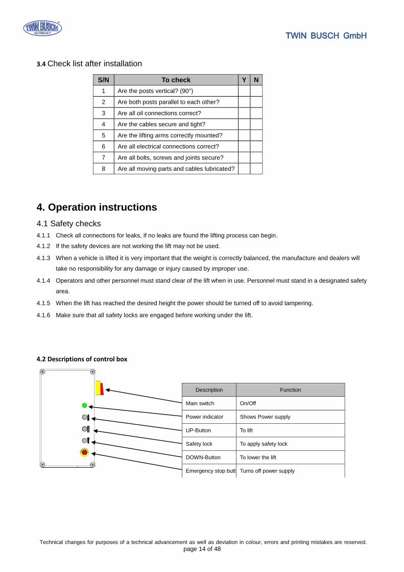
4.2 Descriptions of control box
Description Function
Main switch On/Off
Power indicator Shows Power supply
UP-Button To lift
Safety lock To apply safety lock
DOWN-Button To lower the lift
Emergency stop button Turns off power supply

TWIN BUSCH GmbH
Technical changes for purposes of a technical advancement as well as deviation in colour, errors and printing mistakes are reserved. page 15 of 48
Start
Turn on the power switch
Press UP button
Motor drives the gear pump work
Cylinder piston drives the chain work
Chain drives the carriage rise
The lift is raised
Start
Turn on the power switch
Press the DOWN button
The lift is lowered
4.3 Flow chart for operation
4.4 Operating instructions
Raising the lift
1. Always read the instruction and safety manuals before working with the lift.
2. Drive the vehicle onto the centre of the lift making sure the weight is evenly displaced.
3. Make sure that the vehicle can’t roll or move from the desired position.
4. Turn on the main switch and press the UP button (STOP and check once again that lifting pads are securely positioned)
then raise until the lift has reached the desired height.
5. When the lift has reached the required level press the safety lock button to engage the mechanical safety mechanism.
6. When all safety precautions have been taken, turn off the main switch and check the stability before working on the
Lowering the lift
1. Turn on the power.
2. Press the DOWN (I) button. The lift will automatically rise to disengage the safety mechanism before going down.
The lift will stop at approximately 800mm from the floor.
3. Press the DOWN (II) button to lower the lift, an alarm signal will be heard as the lift descends to the floor.
4. Remove the vehicle.
Raising Lowering

TWIN BUSCH GmbH
Technical changes for purposes of a technical advancement as well as deviation in colour, errors and printing mistakes are reserved. page 16 of 48
4.5 Emergency lowering in case of power cut
When the safety mechanism is not engaged:
a. Release and hold all four Electromagnets, on the posts simultaneously.
b. Turn the valve screw manually.
(Press the screw in and turn left to open and right to close.„OPEN“, „CLOSE“ )
Electromagnet
Electromagnetic valve

TWIN BUSCH GmbH
Technical changes for purposes of a technical advancement as well as deviation in colour, errors and printing mistakes are reserved. page 17 of 48
When the safety mechanism is engaged:
a. Open the hydraulic plug to enable the connection of a manual pump. (Optional).
b. Press the pump lever to fill the cylinder with oil (optional) the safety can now be released.
c. Release all four Electromagnets, on the posts simultaneously.
Repeat process (b)
Hydraulic plug (Hydraulic connection)
Motor
Oil tank
Hydraulic-
connection
Hydraulic-
connection Motor
Oil tank
Hydraulic plug (Hydraulic connection)
Hydraulic pump
Electromagnet

TWIN BUSCH GmbH
Technical changes for purposes of a technical advancement as well as deviation in colour, errors and printing mistakes are reserved. page 18 of 48
Trouble shooting
Attention: Please don’t hesitate to contact us if you can’t solve the problem yourself.
We will help as soon as possible. To help us help you please send a detailed description of your problem with pictures if
possible. This way we can diagnose your problem much quicker.
PROBLEME Cause Solution
Abnormal noise. Excessive wear on the inside of the post. Lubricate the inner side (grease).
Dirt on the post runner. Clean the runners.
Motor does not run /
lift does not rise.
Loose wires Check wires/ connections
Motor is defect. Replace
The limit switch is defect or loose connector Reconnect or replace the switch
Motor runs, lift doesn’t
rise
Motor is running backwards Check wiring.
Pressure valve is loose or blocked. Tighten / Clean.
Gear pump is defect. Replace.
Oil level too low. Top up Oil.
Oil hose loose or damaged. Tighten or replace.
Cushion valve loose or blocked Clean / Tighten
Lift lowers too slowly.
Oil hose is leaking Tighten / Replace.
Cylinder piston leaking Replace gasket.
Direction valve is leaking Clean /replace.
Pressure valve is leaking. Clean / replace.
Manual or electrical release valve is blocked Clean / replace.
Lifting to slow
Oil filter blocked or not sealed Clean / replace.
Oil level too low. Top up oil
Pressure valve wrongly adjusted Adjust
Oil is too hot. (over 45°C) Change oil
Cylinder gasket. Replace
Lift is to slow
Restriction valve blocked Clean / replace.
Hydraulic oil dirty Change oil.
Release valve blocked Clean
Oil hose damaged. Replace
Steel cable is worn Is not lubricated Lubricate / Replace

TWIN BUSCH GmbH
Technical changes for purposes of a technical advancement as well as deviation in colour, errors and printing mistakes are reserved. page 19 of 48
Maintenance
Simple low cost maintenance will enhance the safety and prolong the life of your lift.
The service intervals can be chosen in between working times. Here are the lubrication (greasing points):
6.1. Daily service before use
It’s very important to have a daily safety check before the lift is used. Discovery of worn or defect parts saves time and
expensive repairs, and loss through damages or injuries.
Check oil hoses for leakage and damage.
Check all electrical connections and make sure they are in good condition.
Check that all bolts are securely tightened.
Check that the safety mechanism is working properly and no visible ware can be seen.
6.2. Weekly service
Check all moving parts.
Check the movement of safety parts.
Raise the lift completely to check the oil level, refill if necessary.
Check that all bolts are securely tightened.
6.3. Monthly service
Check that all bolts are securely tightened.
Check that all moving parts have enough lubrication and the whole construction is in good working order.
If damaged parts are discovered they should be replaced
6.4. Yearly service
Empty and clean the oil tank, replace with new oil
Replace the oil filter.
When the user follows the above service suggestions the lift will stay in a good working condition and
unnecessary costs can be avoided.
S/N Description
1 Cable pulley (top)
2 Steel cable
3 Chain wheel
4 Chain
5 Slide
6 Bolt
7 Safety lock
8 Lifting arm
9 Lifting plate
10 Cable pulley (bottom)

TWIN BUSCH GmbH
Technical changes for purposes of a technical advancement as well as deviation in colour, errors and printing mistakes are reserved. page 20 of 48
Attachment (Pack List)
S/N Material # Name Drawing# Property Qty
1 Power side post assembly FL-8224E-A1 Assembly 1
2 Post assembly FL-8224E-A2 Assembly 1
3 Carriage assembly FL-8224E-A3 Assembly 2
4 Power unit Assembly 1
5 Oil cylinder FL-8224-A4-B3 Assembly 1
6 Drive oil cylinder FL-8224-A4-B2 Assembly 1
7 Electrical system Assembly 1
8 Control box 1
9 Wire package 1
10 Steel cable L=8820mm FL-8224E-A6 Assembly 2
11 Long arm FL-8224-A7 Assembly 2
12 Short arm TW-235E-A8 Assembly 2
13
14 Base cover plate FL-8224-A10 Powder-coating 1
Carton(includes the following )
17
18 Arm shaft FL-8224 -A12 Zinc-plating 4
19
20 Short feet-protection fender FL-8224 –A18-B4 Powder-coating 2
21 Long feet-protection fender FL-8224–A7-B4 Powder-coating 2
22 Lifting tray assembly FL-8224 –A7-B3 Assembly 4
23 Rubber oil hose L=500mm Assembly 1
24 Rubber oil hose L=2900mm 8224E-B4-B2 Assembly 1
25 Safety locking plate FL-8224E –A1-B2 Zinc-plating
26
27 Positioning block FL-8224E –A1-B3 Zinc-plating
28 Hose & wire cover FL-8224E –A1-B8 Powder-coating 6
29 Chain protection cloth FL-8224 -A11 Assembly 2
30 Rod of chain protection cloth FL-8224 -A13 Zinc-plating 4
31 Rubber protection pad FL-8224 –A3-B7 Rubber 2
32 Nylon washer FL-8224 -A17 Rubber 10
33
34 Hex head full swivel nut M10*35 Standard 4
35 Hex socket cylinder head screw M8*12 Standard 8
36 Cross cap screw M6*10 Standard 28
37 Cross cap screw M6*30 Standard 12
38 Cross cap screw M6*16 Standard 4
39 Cross sunken head screw M8*16 Standard 4
40 Class C flat washer M6 Standard 8
41 Class C flat washer M10 Standard 4
42 Spring washer M10 Standard 4
Hex nut M6 Standard 8
Hex nut M10 Standard 4
Type B circlip 38 Standard 4
Expansion bolt M18*180 Standard 10

TWIN BUSCH GmbH
Technical changes for purposes of a technical advancement as well as deviation in colour, errors and printing mistakes are reserved. page 21 of 48
Attachment 2, Dimensions diagram

TWIN BUSCH GmbH
Technical changes for purposes of a technical advancement as well as deviation in colour, errors and printing mistakes are reserved. page 22 of 48
Weight Displacement
Model A
(mm)
B
(mm)
C
(mm)
D
(kg)
E
(kg)
F
(kg)
G
(kg)
TW 242 E 2400 2900 100 2300 1900 2300 1900
D E F G

TWIN BUSCH GmbH
Technical changes for purposes of a technical advancement as well as deviation in colour, errors and printing mistakes are reserved. page 23 of 48
New Concrete 28 days drying
Concrete thickness >200 mm
Expansion bolts: M18x10
Floor level <5 mm

TWIN BUSCH GmbH
Technical changes for purposes of a technical advancement as well as deviation in colour, errors and printing mistakes are reserved. page 24 of 48
Requirements for the concrete floor:
Concrete C20 / 25 according to DIN 1045-2 (Previously known as DIN 1045 concrete B25).
Horizontal, accuracy of flatness smaller than 5 mm (0.2”).
New concrete must dry for 28 days.
Foundation dimensions:
Ideally, it’s better to cover the whole area in concrete C20 / 25, 200 mm (up to 4 t)
or 250 mm thick (5 t).
Minimum requirments: 2-Post lift 4 t:
4 m x 3 m x 0,2 m
(13 ft. x 10 ft. x 8 in.)
alternativ H-form alternativ Block-form

TWIN BUSCH GmbH
Technical changes for purposes of a technical advancement as well as deviation in colour, errors and printing mistakes are reserved. page 25 of 48
Other requirements:
The surrounding ground must be suitable for the load, for example, no sand asphalt, etc..
If in doubt, the foundation should always be checked by a structural engineer.
In case of frost, please note the following:
In cases of freezing the concrete should have exposure class XF4.
Thus, the following minimum requirements for the concrete in frost conditions:
Exposure class XF4
Maximum w / c: 0.45
Minimum compressive strength: C30 / 37 (instead of C20 / 25)
Minimum cement content 340 kg / m³
Minimum air content: 4.0%
It must however be noted that the lifting platforms not for use outdoors
The main switch corresponds to IP54, but remaining electrical parts, Motors and limit switches are designed to a
maximum of IP44.
Expansion bolts
Expansion bolts should be tightened to 120 Nm.
Nut
Washer
Base plate
Thread
Concrete

TWIN BUSCH GmbH
Technical changes for purposes of a technical advancement as well as deviation in colour, errors and printing mistakes are reserved. page 26 of 48
Attachment 4, Hydraulic system
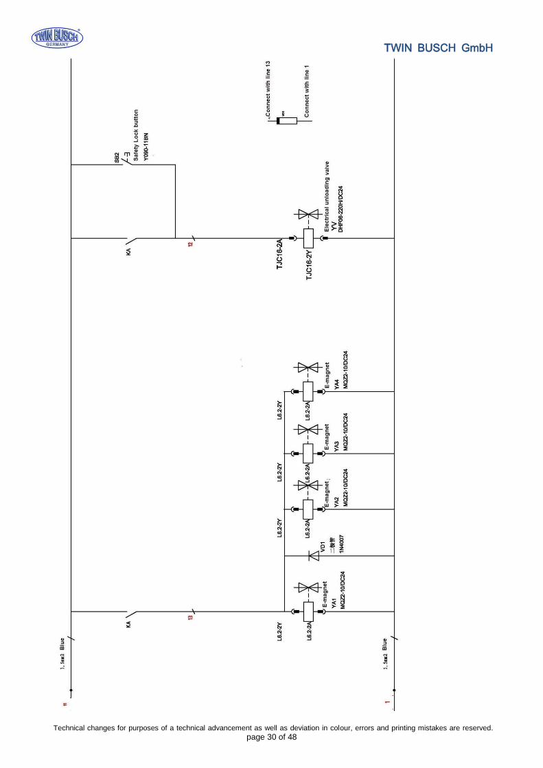
Attachment 5, Wiring diagram
1. Main cylinder
2. Assistant cylinder
3. E-magnetic unloading valve
4. Throttle valve
5. Motor
6. Coupling
7. Gear pump
8. Single-way valve
9. Overflow valve
10. Anti-surge valve
11. Cushion valve
12. Emergent unloading valve

TWIN BUSCH GmbH
Technical changes for purposes of a technical advancement as well as deviation in colour, errors and printing mistakes are reserved. page 27 of 48
Single phase
Three phase

TWIN BUSCH GmbH
Technical changes for purposes of a technical advancement as well as deviation in colour, errors and printing mistakes are reserved. page 28 of 48

TWIN BUSCH GmbH
Technical changes for purposes of a technical advancement as well as deviation in colour, errors and printing mistakes are reserved. page 29 of 48
TWIN BUSCH GmbH
Technical changes for purposes of a technical advancement as well as deviation in colour, errors and printing mistakes are reserved. page 30 of 48

TWIN BUSCH GmbH
Technical changes for purposes of a technical advancement as well as deviation in colour, errors and printing mistakes are reserved. page 31 of 48

TWIN BUSCH GmbH
Technical changes for purposes of a technical advancement as well as deviation in colour, errors and printing mistakes are reserved. page 32 of 48
Attachment 6, Explosion drawings
S/N Name Qty
1 Motor 1
2 Hydraulic block 1
3 Overflow valve 1
4 Removable plug 2
5 Cushion valve 1
6 Oil absorbing pipe 1
7 Oil filter 1
8 Throttle valve 1
9 Oil pipe tie-in 1
10 E-magnetic unloading valve 1
11 One-way valve 1
12 Gear pump 1
13 Plastic oil tank 1
14 Oil tank cover 1
15 Oil back pipe 1

TWIN BUSCH GmbH
Technical changes for purposes of a technical advancement as well as deviation in colour, errors and printing mistakes are reserved. page 33 of 48
S/N Material # Name Drawing# Qty Property Note
4 Rubber oil hose L=2900 1 Assembly
5 Power unit (electrical release) 1 Assembly
6 PU oil hose L=500 1 Assembly
7 Composite connector 2 Assembly
8 Composite washer Match with 1/4connector 4 Standard
9 Square Connector 1 Assembly
10 Drive oil cylinder FL-8224-A4-B2 1 Assembly
11 Chain wheel bracket FL-8224-A4-B9 2 Zinc -plating
12 Type B circlip 25 GB/T894.2-1986 4 Standard
13 Chain wheel shaft FL-8224-A4-B11 2 Zinc -plating
14 Bearing 2548 SF-1 2 Standard
15 Chain wheel FL-8224-A4-B10 2 Zinc -plating
16 Baffle plate FL-8224-A4-B12 2 Zinc -plating
17 Spring washer M6 GB/T93-1987 4 Standard
18 Inside hex cylinder head screw M6*10 GB/T70.1-2000 4 Standard
19 Chain LH1234-127LGB/6074-1995 2 Standard
20 Assistant oil cylinder FL-8224-A4-B3 1 Assembly
98 Main oil cylinder connector FL-8224-A4-B4 1 Zinc -plating
99 Assistant oil cylinder connector FL-8224-A4-B5 1 Zinc -plating
S/N Material # Name Drawing# Qty Property Note
1 Steel cable L=8820mm FL8224-A6 2 Assembly
2 Hex nut M16 GB/T610-2000 8 Standard
3 Class C flat washer M16 GB/T95-1985 4 Standard
4 Expansion bolt M18*180 10 Standard

TWIN BUSCH GmbH
Technical changes for purposes of a technical advancement as well as deviation in colour, errors and printing mistakes are reserved. page 34 of 48
S/N Material # Name Drawing# Qty Property Note
21 Positioning block FL-8224E-A1-B3 4 Zinc-plating
22 Safety locking plate FL-8224E-A1-B2 4 Zinc-plating
23 Cross cap screw M6*16 GB/T818-2000 4 Standard
24 Cross cap screw M5*10 GB/T818-2000 8 Standard
25 Electromagnet protection cover FL-8224E-A1-B5 4 Plastic
26 φ20 hose clip FL-8224-A1-B6 2 Rubber
27 Cross cap screw M5*10 GB/T818-2000 16 Standard
28 Tractive electromagnet FL-8224E-A1-B6 4 Assembly
S/N Material # Name Drawing# Qty Property Note
29 Hex socket cylinder head screw M8*20 GB/T70.2-2000 2 Standard
30 Spring washer M8 GB/T93-1987 2 Standard
31 Retaining ring FL-8224-A1-B3-C
2
2 Zinc-plating
32 Washer GB/T894.2-1986 2 Zinc-plating
33 Up pulley FL-8224-A1-B2 2 Zinc-plating
34 Bearing 2518 SF-1 2 Standard
35 Top plate FL-8224-A1-B3-C
1
2 Welded

TWIN BUSCH GmbH
Technical changes for purposes of a technical advancement as well as deviation in colour, errors and printing mistakes are reserved. page 35 of 48
S/N Material # Name Drawing# Qty Property Note
36 Type B circlip 25 GB/T894.2-1986 4 Standard
37
38 Bearing 2516 SF-1 4 Standard
39 Down pulley FL-8224-A1-B2 4 Zinc-plating
40 Slider FL-8224-A3-B6 16 Nylon
41 Pulling rod FL-8224-A3-B2 4 Zinc-plating
42 Pressure spring FL-8224-A3-B5 4 Zinc-plating
43 Teeth block FL-8224-A3-B6 4 Zinc-plating
44 Elastic pin 5*35 GB/T879.1-2000 4 Standard
45 Type B circlip 22 GB/T894.2-1986 4 Standard
46 Pin shaft assembly FL-8224E-A12 4 Zinc-plating
47 Cross socket flat head screw M8*16 GB/T819.1-2000 4 Standard
48 Protection rubber pad FL-8224-A3-B7 2 Rubber
49 Carriage assembly FL-8224-A3-B1 2 Welded

TWIN BUSCH GmbH
Technical changes for purposes of a technical advancement as well as deviation in colour, errors and printing mistakes are reserved. page 36 of 48

TWIN BUSCH GmbH
Technical changes for purposes of a technical advancement as well as deviation in colour, errors and printing mistakes are reserved. page 37 of 48
S/N Material # Name Drawing# Qty Property Note
51 Top plate FL-8224-A1-B3 2 Assembly
52 Class C flat washer M12 GB/T95-1985 4 Standard
53 Spring washer M12 GB/T93-1987 4 Standard
54 Hex head full swivel screw M12*20 GB/T5781-2000 4 Standard
55 Hex nut M6 GB/T6170-2000 8 Standard
56 Class C flat washer M6 GB/T95-1985 4 Standard
57 Rod of chain protection cloth FL-8224-A13 4 Standard
58 Chain protection FL-8224-A11 2 Cloth
59 Cross socket flat head screw M5*10 GB/T819.1-2000 16 Standard
60 Rectangular protection pad FL-8224-A7-B7 4 Rubber
61 Cross socket flat head screw M8*10 GB/T819.1-2000 4 Standard
62 Inside hex sunken head screw M8*20 GB/T70.3-2000 8 Standard
63 Round lifting pad FL-8224-A7-B3-C4 4 Rubber
64 Lifting tray FL-8224-A7-B3-C1 4 Assembly
65 Type B circlip 22 GB/T894.2-1986 4 Standard
66 Swivel sheath FL-8224-A7-B3-C2 4 Q235A
67 Circlip 38*2.5 GB/T895.2-1986 8 Standard
68 Inside swivel sheath FL-8224-A7-B3-C3 4 Q235A
69 Cross cap screw M6*8 GB/T818-2000 4 Standard
70 Class C flat washer M6 GB/T95-1985 4 Standard
71 Inside hex sunken head screw M12*20 GB/T70.3-2000 2 Standard
72 Base plate FL-8224-A10 1 Q235A
73 Slot base plate FL-8224-A9 1 Welded
74 Long tensile arm FL-8224-A7-B2 2 Welded
75 Long feet protection fender FL-8224-A7-B4 2 Welded
76 Long arm FL-8224-A7-B1 2 Welded
77 Teeth block FL-8224-A7-B5 4 Q235A
78 Hex socket cap screw M10*20 GB/T70.1-2000 12 Standard
79 Arm shaft FL-8224-A12 4 Welded
80 Hex nut M8 GB/T6170-2000 4 Standard
81 Spring washer M8 GB/T93-1987 4 Standard
82 Anti-shock pad FL-8224-A14 4 Rubber
83 Class C flat washer M8 GB/T95-1985 4 Standard
84 Hex head full swivel screw M8*35 GB/T5781-2000 4 Standard
85 Φ40 hose clip FL-8224-A1-B7 2 Rubber
86 Control box FL-8224E 1 Assembly
87 Cross cap screw M5*10 GB/T818-2000 4 Standard
88 Short arm FL-8224-A18-B1 2 Welded
89 Short tensile arm TW-235E-A20-B1 2 Welded
90 Hex socket cylinder head screw M8*12 GB/T70.2-2000 8 Standard
91 Short feet protection fender FL-8224-A18-B4 2 Welded
92 Height adapter FL-8224-A15 4 Welded
93 Type B circlip 38 GB/T894.2-1986 4 Standard
95 Cross cap screw M6*30 GB/T818-2000 12 Standard
96
Hose &wire cover FL-8224E-A1-B8 6 Q235A

TWIN BUSCH GmbH
Technical changes for purposes of a technical advancement as well as deviation in colour, errors and printing mistakes are reserved. page 38 of 48
Attachment 7, Spare parts list
S/N Material # Name Spec. Qty Pic. Note
1 Power switch LW26GS-20/04 1
2 Button LAY711BN12 1
3 Power indicator AD17-22G-AC24 1
4 Transformer
JBK3-160VA400V-24V
Bk一 160VA110V一
24V一 60HZ
1
5
AC contactor
CJX2-1210/AC24V
CJX2-3210- AC24V 1
6 Circuit breaker
DZ47-63 C16/3P
DZ47-63 C32/2P
1
7 Circuit breaker DZ47-63 C3/1P 1
9 Limit switch ME8104 1
11 Emergency stop LAY701ZS42 1
12 Bridge rectifier KBPC5A-35A 1
13 Capacitor 4700UF/50A 1
14 Relay LY2NJ/AC24 1
15 Relay holder PTF-08A 1
S/N Material # Name Drawing# Qty Property Note
1 Slider FL-8224-A3-B6
16 Nylon 1010
2 Rubber lifting pad FL-8224-A7-B3-C4
8224E-A7-B4-C4
4 Rubber
3 Y-shape seal ring KD 63*48*10 1
4 O-shape seal ring (ID)23.6*3.55 1
5 Anti-dust ring DHS 40*48*5/6.5 1

TWIN BUSCH GmbH
Technical changes for purposes of a technical advancement as well as deviation in colour, errors and printing mistakes are reserved. page 39 of 48
S/N Material # Name Spec. Qty Pic. Note
16 time relay ST6PA-5S/AC24V 1
17 Time relay holder PYF-08AE 1
18 Control box 380*260*135 1

TWIN BUSCH GmbH
Technical changes for purposes of a technical advancement as well as deviation in colour, errors and printing mistakes are reserved. page 40 of 48
Space for notes:

TWIN BUSCH GmbH
Technical changes for purposes of a technical advancement as well as deviation in colour, errors and printing mistakes are reserved. page 41 of 48
Space for notes:

TWIN BUSCH GmbH
Technical changes for purposes of a technical advancement as well as deviation in colour, errors and printing mistakes are reserved. page 42 of 48

TWIN BUSCH GmbH
Technical changes for purposes of a technical advancement as well as deviation in colour, errors and printing mistakes are reserved. page 43 of 48

TWIN BUSCH GmbH
Technical changes for purposes of a technical advancement as well as deviation in colour, errors and printing mistakes are reserved. page 44 of 48

TWIN BUSCH GmbH
Technical changes for purposes of a technical advancement as well as deviation in colour, errors and printing mistakes are reserved. page 45 of 48

TWIN BUSCH GmbH
Technical changes for purposes of a technical advancement as well as deviation in colour, errors and printing mistakes are reserved. page 46 of 48

TWIN BUSCH GmbH
Technical changes for purposes of a technical advancement as well as deviation in colour, errors and printing mistakes are reserved. page 47 of 48

TWIN BUSCH GmbH
Technical changes for purposes of a technical advancement as well as deviation in colour, errors and printing mistakes are reserved. page 48 of 48