installation, operation, and maintenance … april 8, 1981 rev. b 5‐31‐2013 the gorman‐rupp...
TRANSCRIPT
OM-01096-04April 8, 1981
Rev. B 5‐31‐2013
THE GORMAN‐RUPP COMPANY � MANSFIELD, OHIOwww.grpumps.com
GORMAN‐RUPP OF CANADA LIMITED � ST. THOMAS, ONTARIO, CANADA Printed in U.S.A.
�1981 The Gorman‐Rupp Company
INSTALLATION, OPERATION,
AND MAINTENANCE MANUALWITH PARTS LIST
0 SERIES PUMP
MODEL
02C3-X1.5 3P
Register your newGorman‐Rupp pump online atwww.grpumps.com/register.
Valid serial number and e‐mail address required.
RECORD YOUR PUMP MODEL AND SERIAL NUMBER
Please record your pump model and serial number in thespaces provided below. Your Gorman‐Rupp distributorneeds this information when you require parts or service.
Pump Model:
Serial Number:
TABLE OF CONTENTS
i
INTRODUCTION PAGE I - 1. . . . . . . . . . . . . . . . . . . . . . . . . . . . . . . . . . . . . . . . . . . . . . . . .
SAFETY - SECTION A PAGE A - 1. . . . . . . . . . . . . . . . . . . . . . . . . . . . . . . . . . . . . . . . . . .
INSTALLATION - SECTION B PAGE B - 1. . . . . . . . . . . . . . . . . . . . . . . . . . . . . . . . . . . .
Pump Dimensions PAGE B - 1. . . . . . . . . . . . . . . . . . . . . . . . . . . . . . . . . . . . . . . . . . . . . . . . . . . . .
PREINSTALLATION INSPECTION PAGE B - 2. . . . . . . . . . . . . . . . . . . . . . . . . . . . . . . . . . . . . . . . . . . .
POSITIONING PUMP PAGE B - 2. . . . . . . . . . . . . . . . . . . . . . . . . . . . . . . . . . . . . . . . . . . . . . . . . . . . . . .
Lifting PAGE B - 2. . . . . . . . . . . . . . . . . . . . . . . . . . . . . . . . . . . . . . . . . . . . . . . . . . . . . . . . . . . . . . . . .
Mounting PAGE B - 2. . . . . . . . . . . . . . . . . . . . . . . . . . . . . . . . . . . . . . . . . . . . . . . . . . . . . . . . . . . . .
SUCTION AND DISCHARGE PIPING PAGE B - 2. . . . . . . . . . . . . . . . . . . . . . . . . . . . . . . . . . . . . . . . .
Materials PAGE B - 3. . . . . . . . . . . . . . . . . . . . . . . . . . . . . . . . . . . . . . . . . . . . . . . . . . . . . . . . . . . . . .
Line Configuration PAGE B - 3. . . . . . . . . . . . . . . . . . . . . . . . . . . . . . . . . . . . . . . . . . . . . . . . . . . . . .
Connections to Pump PAGE B - 3. . . . . . . . . . . . . . . . . . . . . . . . . . . . . . . . . . . . . . . . . . . . . . . . . .
Gauges PAGE B - 3. . . . . . . . . . . . . . . . . . . . . . . . . . . . . . . . . . . . . . . . . . . . . . . . . . . . . . . . . . . . . . .
SUCTION LINES PAGE B - 3. . . . . . . . . . . . . . . . . . . . . . . . . . . . . . . . . . . . . . . . . . . . . . . . . . . . . . . . . . .
Fittings PAGE B - 3. . . . . . . . . . . . . . . . . . . . . . . . . . . . . . . . . . . . . . . . . . . . . . . . . . . . . . . . . . . . . . .
Strainers PAGE B - 3. . . . . . . . . . . . . . . . . . . . . . . . . . . . . . . . . . . . . . . . . . . . . . . . . . . . . . . . . . . . . .
Sealing PAGE B - 3. . . . . . . . . . . . . . . . . . . . . . . . . . . . . . . . . . . . . . . . . . . . . . . . . . . . . . . . . . . . . . .
Suction Lines In Sumps PAGE B - 3. . . . . . . . . . . . . . . . . . . . . . . . . . . . . . . . . . . . . . . . . . . . . . . . .
Suction Line Positioning PAGE B - 4. . . . . . . . . . . . . . . . . . . . . . . . . . . . . . . . . . . . . . . . . . . . . . . .
DISCHARGE LINES PAGE B - 4. . . . . . . . . . . . . . . . . . . . . . . . . . . . . . . . . . . . . . . . . . . . . . . . . . . . . . . .
Siphoning PAGE B - 4. . . . . . . . . . . . . . . . . . . . . . . . . . . . . . . . . . . . . . . . . . . . . . . . . . . . . . . . . . . . .
Valves PAGE B - 4. . . . . . . . . . . . . . . . . . . . . . . . . . . . . . . . . . . . . . . . . . . . . . . . . . . . . . . . . . . . . . . .
Bypass Lines PAGE B - 5. . . . . . . . . . . . . . . . . . . . . . . . . . . . . . . . . . . . . . . . . . . . . . . . . . . . . . . . . .
ELECTRICAL CONNECTIONS PAGE B - 5. . . . . . . . . . . . . . . . . . . . . . . . . . . . . . . . . . . . . . . . . . . . . . .
OPERATION - SECTION C PAGE C - 1. . . . . . . . . . . . . . . . . . . . . . . . . . . . . . . . . . . . . .
PRIMING PAGE C - 1. . . . . . . . . . . . . . . . . . . . . . . . . . . . . . . . . . . . . . . . . . . . . . . . . . . . . . . . . . . . . . . . .
STARTING PAGE C - 1. . . . . . . . . . . . . . . . . . . . . . . . . . . . . . . . . . . . . . . . . . . . . . . . . . . . . . . . . . . . . . . .
OPERATION PAGE C - 1. . . . . . . . . . . . . . . . . . . . . . . . . . . . . . . . . . . . . . . . . . . . . . . . . . . . . . . . . . . . . .
Lines With a Bypass PAGE C - 1. . . . . . . . . . . . . . . . . . . . . . . . . . . . . . . . . . . . . . . . . . . . . . . . . . . .
Lines Without a Bypass PAGE C - 2. . . . . . . . . . . . . . . . . . . . . . . . . . . . . . . . . . . . . . . . . . . . . . . . .
Leakage PAGE C - 2. . . . . . . . . . . . . . . . . . . . . . . . . . . . . . . . . . . . . . . . . . . . . . . . . . . . . . . . . . . . . .
Liquid Temperature And Overheating PAGE C - 2. . . . . . . . . . . . . . . . . . . . . . . . . . . . . . . . . . . . .
Strainer Check PAGE C - 2. . . . . . . . . . . . . . . . . . . . . . . . . . . . . . . . . . . . . . . . . . . . . . . . . . . . . . . . .
Pump Vacuum Check PAGE C - 2. . . . . . . . . . . . . . . . . . . . . . . . . . . . . . . . . . . . . . . . . . . . . . . . . .
STOPPING PAGE C - 3. . . . . . . . . . . . . . . . . . . . . . . . . . . . . . . . . . . . . . . . . . . . . . . . . . . . . . . . . . . . . . . .
Cold Weather Preservation PAGE C - 3. . . . . . . . . . . . . . . . . . . . . . . . . . . . . . . . . . . . . . . . . . . . . .
TROUBLESHOOTING - SECTION D PAGE D - 1. . . . . . . . . . . . . . . . . . . . . . . . . . . . . .
PREVENTIVE MAINTENANCE PAGE D - 3. . . . . . . . . . . . . . . . . . . . . . . . . . . . . . . . . . . . . . . . . . .
PUMP MAINTENANCE AND REPAIR - SECTION E PAGE E - 1. . . . . . . . . . . . . . . .
PERFORMANCE CURVE PAGE E - 1. . . . . . . . . . . . . . . . . . . . . . . . . . . . . . . . . . . . . . . . . . . . . . . . . . .
PARTS LIST:
TABLE OF CONTENTS
(continued)
ii
Pump Model PAGE E - 3. . . . . . . . . . . . . . . . . . . . . . . . . . . . . . . . . . . . . . . . . . . . . . . . . . . . . . . . . .
PUMP AND SEAL DISASSEMBLY AND REASSEMBLY PAGE E - 4. . . . . . . . . . . . . . . . . . . . . . . . .
Pump Disassembly PAGE E - 4. . . . . . . . . . . . . . . . . . . . . . . . . . . . . . . . . . . . . . . . . . . . . . . . . . . . .
Impeller Removal PAGE E - 4. . . . . . . . . . . . . . . . . . . . . . . . . . . . . . . . . . . . . . . . . . . . . . . . . . . . . .
Seal Removal and Disassembly PAGE E - 5. . . . . . . . . . . . . . . . . . . . . . . . . . . . . . . . . . . . . . . . . .
Seal Reassembly and Installation PAGE E - 5. . . . . . . . . . . . . . . . . . . . . . . . . . . . . . . . . . . . . . . .
Impeller Installation PAGE E - 6. . . . . . . . . . . . . . . . . . . . . . . . . . . . . . . . . . . . . . . . . . . . . . . . . . . . .
Pump Reassembly PAGE E - 7. . . . . . . . . . . . . . . . . . . . . . . . . . . . . . . . . . . . . . . . . . . . . . . . . . . . .
Final Pump Assembly PAGE E - 7. . . . . . . . . . . . . . . . . . . . . . . . . . . . . . . . . . . . . . . . . . . . . . . . . .
LUBRICATION PAGE E - 7. . . . . . . . . . . . . . . . . . . . . . . . . . . . . . . . . . . . . . . . . . . . . . . . . . . . . . . . . . . . .
Seal Assembly PAGE E - 7. . . . . . . . . . . . . . . . . . . . . . . . . . . . . . . . . . . . . . . . . . . . . . . . . . . . . . . . .
0 SERIES OM-01096
PAGE I - 1INTRODUCTION
INTRODUCTION
Thank You for purchasing a Gorman‐Rupp pump.
Read this manual carefully to learn how to safely
install and operate your pump. Failure to do so
could result in personal injury or damage to the
pump.
This Installation, Operation, and Maintenance
manual is designed to help you achieve the best
performance and longest life from your Gorman‐
Rupp pump.
This pump is an 0 Series, enclosed impeller, self‐
priming centrifugal model with straight‐in suction,
without a suction check valve and close‐coupled to
an explosion‐proof electric motor. The pump is de
signed for handling clean liquids that do not con
tain large entrained solids. The basic material of
construction is gray iron, with bronze impeller and
stainless steel impeller shaft.
If there are any questions regarding the pump or
its application which are not covered in this man
ual or in other literature accompanying this unit,
please contact your Gorman‐Rupp distributor, or:
The Gorman‐Rupp Company
P.O. Box 1217
Mansfield, Ohio 44901-1217
Phone: (419) 755-1011
or:
Gorman‐Rupp of Canada Limited
70 Burwell Road
St. Thomas, Ontario N5P 3R7
Phone: (519) 631-2870
For information or technical assistance on the mo
tor, contact the motor manufacturer's local dealer
or representative.
This manual will alert personnel to known proce
dures which require special attention, to those
which could damage equipment, and to those
which could be dangerous to personnel. However,
this manual cannot possibly anticipate and provide
detailed precautions for every situation that might
occur during maintenance of the unit. Therefore, it
is the responsibility of the owner/maintenance per
sonnel to ensure that only safe, established main
tenance procedures are used, and that any proce
dures not addressed in this manual are performed
only after establishing that neither personal safety
nor pump integrity are compromised by such prac
tices.
The following are used to alert maintenance per
sonnel to procedures which require special atten
tion, to those which could damage equipment, and
to those which could be dangerous to personnel:
Immediate hazards which WILL result insevere personal injury or death. Theseinstructions describe the procedure required and the injury which will resultfrom failure to follow the procedure.
Hazards or unsafe practices whichCOULD result in severe personal injuryor death. These instructions describethe procedure required and the injurywhich could result from failure to followthe procedure.
Hazards or unsafe practices which COULDresult in minor personal injury or productor property damage. These instructionsdescribe the requirements and the possible damage which could result from failureto follow the procedure.
NOTEInstructions to aid in installation, operation, and
maintenance or which clarify a procedure.
0 SERIES OM-01096
PAGE A - 1SAFETY
SAFETY - SECTION A
This information applies to 0 Serieselectric motor driven pumps. Refer tothe manual accompanying the motorbefore attempting to begin operation.
This manual will alert personnel toknown procedures which require special attention, to those which coulddamage equipment, and to those whichcould be dangerous to personnel. However, this manual cannot possibly provide detailed instructions and precautions for each specific application or forevery situation that might occur duringmaintenance of the unit. Therefore, it isthe responsibility of the owner, installerand/or maintenance personnel to ensure that applications and/or maintenance procedures not addressed in thismanual are performed only after establishing that neither personal safety norpump integrity are compromised bysuch applications or procedures.
Before attempting to open or service thepump:
1. Familiarize yourself with this man
ual.
2. Disconnect the incoming power to
the motor and lock it out to ensure
that the pump will remain inopera
tive.
3. Allow the pump to completely cool
if overheated.
4. Check the temperature before
opening any covers, plates, or
plugs.
5. Close the suction and discharge
valves.
6. Vent the pump slowly and cau
tiously.
7. Drain the pump.
This pump is designed to handle petroleum products or other industrial liquids that do not contain large entrainedsolids. Do not attempt to pump volatile,corrosive, or flammable materials whichmay damage the pump or endanger personnel as a result of pump failure.
This pump is designed to handle petroleum products or other industrial liquids that do not contain large entrainedsolids. All controls must meet industrystandards and codes for use in an explosive atmosphere. Do not attempt topump liquids for which the pump and/orcontrols have not been approved, orwhich may damage the pump or endanger personnel as a result of pump failure.
Be certain proper safety practices arefollowed before operating or servicingthe pump. Provide adequate ventilation,prohibit smoking, wear static‐resistantclothing and shoes. Clean up all fuelspills immediately after occurrence.
Do not install and operate a non‐explosion proof motor in an explosive atmosphere. Install, connect, and operatethe motor in accordance with the National Electric Code and all local codes.If there is a conflict between the instructions in the manual accompanying theunit and the National Electric Code or
0 SERIESOM-01096
PAGE A - 2 SAFETY
the applicable local code, the Nationalor local code shall take precedence.
Because this pump is designed to handle volatile and/or flammable liquids,overheating may produce dangerousfumes. Take precautions to ensure thearea surrounding the pump is adequately ventilated. Allow the pump tocool and use extreme caution whenventing the pump, or when removingcovers, plates, plugs, or fittings.
After the pump has been positioned,make certain that the pump and all piping connections are tight, properly supported and secure before operation.
Do not remove plates, covers, gauges,pipe plugs, or fittings from an overheated pump. Vapor pressure within thepump can cause parts being disengaged to be ejected with great force. Allow the pump to cool before servicing.
Do not operate the pump against aclosed discharge valve for long periodsof time. If operated against a closed discharge valve, pump components willdeteriorate, and the liquid could cometo a boil, build pressure, and cause thepump casing to rupture or explode.
Overheated pumps can cause severeburns and injuries. If overheating of thepump occurs:
1. Stop the pump immediately.2. Ventilate the area.3. Allow the pump to completely cool.4. Check the temperature before
opening any covers, plates,gauges, or plugs.
5. Vent the pump slowly and cautiously.
6. Refer to instructions in this manualbefore restarting the pump.
The electrical power used to operatethis pump is high enough to cause injury or death. Obtain the services of a qualified electrician to troubleshoot, testand/or service the electrical components of this pump.
Use lifting and moving equipment ingood repair and with adequate capacityto prevent injuries to personnel or damage to equipment. Suction and discharge hoses and piping must be removed from the pump before lifting.
Pumps and related equipment must be installed and operated according to all national, local and industry standards.
OM-010960 SERIES
PAGE B - 1INSTALLATION
INSTALLATION - SECTION B
Review all SAFETY information in Section A.
Since pump installations are seldom identical, this
section offers only general recommendations and
practices required to inspect, position, and ar
range the pump and piping.
Most of the information pertains to a standard
static lift application where the pump is posi
tioned above the free level of liquid to be pumped.
If installed in a flooded suction application where
the liquid is supplied to the pump under pressure,
some of the information such as mounting, line
configuration, and priming must be tailored to the
specific application. Since the pressure supplied
to the pump is critical to performance and safety,
be sure to limit the incoming pressure to 50% of
the maximum permissible operating pressure as
shown on the pump performance curve.
For further assistance, contact your Gorman‐Rupp
distributor or the Gorman‐Rupp Company.
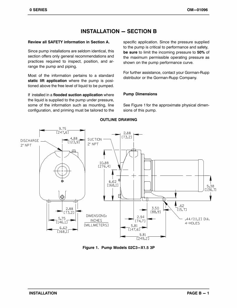
Pump Dimensions
See Figure 1 for the approximate physical dimen
sions of this pump.
OUTLINE DRAWING
Figure 1. Pump Models 02C3-X1.5 3P
OM-01096 0 SERIES
PAGE B - 2 INSTALLATION
PREINSTALLATION INSPECTION
The pump assembly was inspected and tested be
fore shipment from the factory. Before installation,
inspect the pump for damage which may have oc
curred during shipment. Check as follows:
a. Inspect the pump and motor for cracks,
dents, damaged threads, and other obvious
damage.
b. Check for and tighten loose attaching hard
ware. Since gaskets tend to shrink after dry
ing, check for loose hardware at mating sur
faces.
c. Carefully read all warnings and cautions con
tained in this manual or affixed to the pump,
and perform all duties indicated. Note the di
rection of rotation indicated on the pump.
Check that the pump shaft rotates counter
clockwise when facing the impeller.
Only operate this pump in the direction indicated by the arrow on the pump bodyand on the accompanying decal. Refer toROTATION in OPERATION, Section C.
d. Check levels and lubricate as necessary. Re
fer to LUBRICATION in the MAINTENANCE
AND REPAIR section of this manual and per
form duties as instructed.
e. If the pump and motor have been stored for
more than 12 months, some of the compo
nents or lubricants may have exceeded their
maximum shelf life. These must be inspected
or replaced to ensure maximum pump serv
ice.
If the maximum shelf life has been exceeded, or if
anything appears to be abnormal, contact your
Gorman‐Rupp distributor or the factory to deter
mine the repair or updating policy. Do not put the
pump into service until appropriate action has
been taken.
The electrical power used to operatethis pump is high enough to cause injury or death. Obtain the services of a qualified electrician to troubleshoot, testand/or service the electrical components of this pump.
POSITIONING PUMP
Lifting
Pump unit weights will vary depending on the
mounting and drive provided. Check the shipping
tag on the unit packaging for the actual weight, and
use lifting equipment with appropriate capacity.
Drain the pump and remove all customer‐installed
equipment such as suction and discharge hoses
or piping before attempting to lift existing, installed
units.
The pump assembly can be seriouslydamaged if the cables or chains used to liftand move the unit are improperly wrappedaround the pump.
Mounting
Locate the pump in an accessible place as close as
practical to the liquid being pumped. Level mount
ing is essential for proper operation.
The intermediate is equipped with mounting foot
holes for mounting the pump to a base.
SUCTION AND DISCHARGE PIPING
Pump performance is adversely effected by in
creased suction lift, discharge elevation, and fric
tion losses. See the performance curve and oper
ating range shown on Page E‐1 to be sure your
overall application allows pump to operate within
the safe operation range.
OM-010960 SERIES
PAGE B - 3INSTALLATION
Materials
Either pipe or hose maybe used for suction and
discharge lines; however, the materials must be
compatible with the liquid being pumped. If hose is
used in suction lines, it must be the rigid‐wall, rein
forced type to prevent collapse under suction. Us
ing piping couplings in suction lines is not recom
mended.
Line Configuration
Keep suction and discharge lines as straight as
possible to minimize friction losses. Make mini
mum use of elbows and fittings, which substan
tially increase friction loss. If elbows are necessary,
use the long‐radius type to minimize friction loss.
Connections to Pump
Before tightening a connecting flange, align it ex
actly with the pump port. Never pull a pipe line into
place by tightening the flange bolts and/or cou
plings.
Lines near the pump must be independently sup
ported to avoid strain on the pump which could
cause excessive vibration, decreased bearing life,
and increased shaft and seal wear. If hose‐type
lines are used, they should have adequate support
to secure them when filled with liquid and under
pressure.
Gauges
Most pumps are drilled and tapped for installing
discharge pressure and vacuum suction gauges.
If these gauges are desired for pumps that are not
tapped, drill and tap the suction and discharge
lines not less than 18 inches (457,2 mm) from the
suction and discharge ports and install the lines.
Installation closer to the pump may result in erratic
readings.
SUCTION LINES
To avoid air pockets which could affect pump prim
ing, the suction line must be as short and direct as
possible. When operation involves a suction lift, the
line must always slope upward to the pump from
the source of the liquid being pumped; if the line
slopes down to the pump at any point along the
suction run, air pockets will be created.
Fittings
Suction lines should be the same size as the pump
inlet. If reducers are used in suction lines, they
should be the eccentric type, and should be in
stalled with the flat part of the reducers uppermost
to avoid creating air pockets. Valves are not nor
mally used in suction lines, but if a valve is used,
install it with the stem horizontal to avoid air pock
ets.
Strainers
If a strainer is furnished with the pump, be certain
to use it; any spherical solids which pass through a
strainer furnished with the pump will also pass
through the pump itself.
If a strainer is not furnished with the pump, but is
installed by the pump user, make certain that the
total area of the openings in the strainer is at least
three or four times the cross section of the suction
line, and that the openings will not permit passage
of solids larger than the solids handling capability
of the pump.
This pump is designed to handle up to 11/32‐inch
(8,7 mm) diameter spherical solids.
Sealing
Since even a slight leak will affect priming, head,
and capacity, especially when operating with a
high suction lift, all connections in the suction line
should be sealed with pipe dope to ensure an air
tight seal. Follow the sealant manufacturer's rec
ommendations when selecting and applying the
pipe dope. The pipe dope should be compatible
with the liquid being pumped.
Suction Lines In Sumps
If a single suction line is installed in a sump, it
should be positioned away from the wall of the
sump at a distance equal to 1 1/2 times the diame
ter of the suction line.
OM-01096 0 SERIES
PAGE B - 4 INSTALLATION
If there is a liquid flow from an open pipe into the
sump, the flow should be kept away from the suc
tion inlet because the inflow will carry air down into
the sump, and air entering the suction line will re
duce pump efficiency.
If it is necessary to position inflow close to the suc
tion inlet, install a baffle between the inflow and the
suction inlet at a distance 1 1/2 times the diameter
of the suction pipe. The baffle will allow entrained
air to escape from the liquid before it is drawn into
the suction inlet.
If two suction lines are installed in a single sump,
the flow paths may interact, reducing the efficiency
of one or both pumps. To avoid this, position the
suction inlets so that they are separated by a dis
tance equal to at least 3 times the diameter of the
suction pipe.
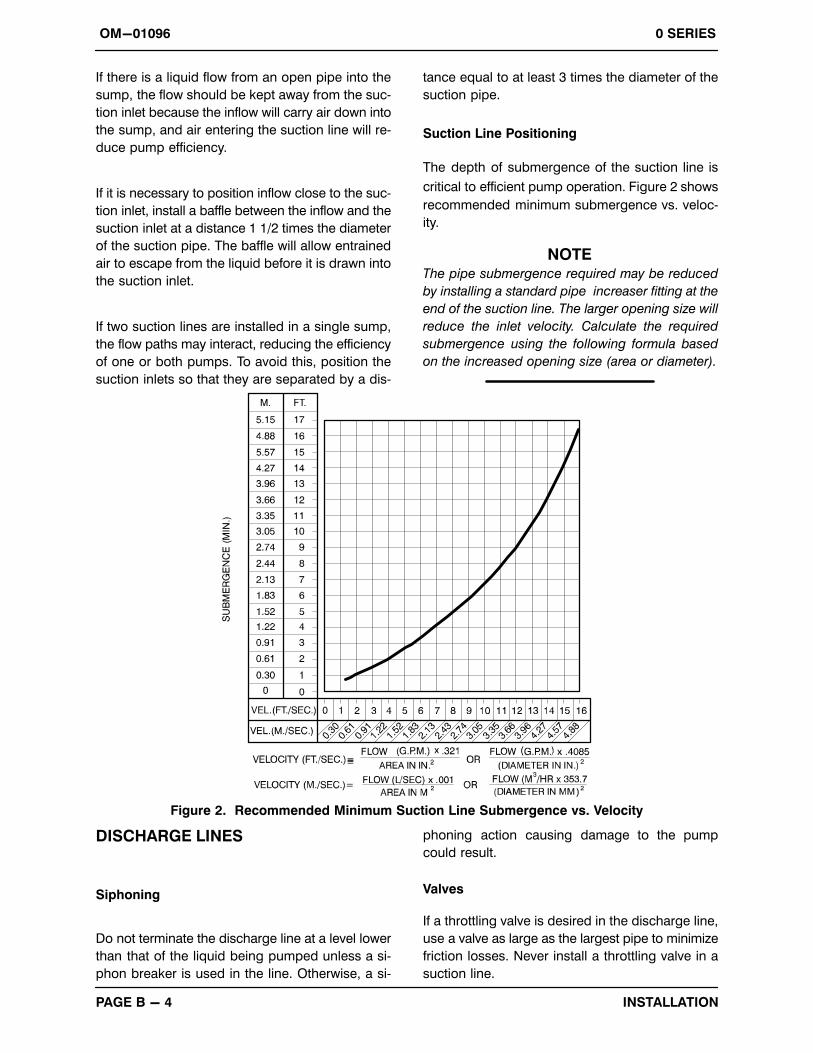
Suction Line Positioning
The depth of submergence of the suction line is
critical to efficient pump operation. Figure 2 shows
recommended minimum submergence vs. veloc
ity.
NOTEThe pipe submergence required may be reduced
by installing a standard pipe increaser fitting at the
end of the suction line. The larger opening size will
reduce the inlet velocity. Calculate the required
submergence using the following formula based
on the increased opening size (area or diameter).
Figure 2. Recommended Minimum Suction Line Submergence vs. Velocity
DISCHARGE LINES
Siphoning
Do not terminate the discharge line at a level lower
than that of the liquid being pumped unless a si
phon breaker is used in the line. Otherwise, a si
phoning action causing damage to the pump
could result.
Valves
If a throttling valve is desired in the discharge line,
use a valve as large as the largest pipe to minimize
friction losses. Never install a throttling valve in a
suction line.
OM-010960 SERIES
PAGE B - 5INSTALLATION
A check valve in the discharge line is normally rec
ommended, but it is not necessary in low dis
charge head applications.
With high discharge heads, it is recommended that
a throttling valve and a system check valve be in
stalled in the discharge line to protect the pump
from excessive shock pressure and reverse rota
tion when it is stopped.
If the application involves a high dischargehead, gradually close the dischargethrottling valve before stopping the pump.
Bypass Lines
If it is necessary to permit the escape of air to atmo
sphere on initial priming or during the repriming
cycle, install an air bypass line ‐ sized so that it will
not affect the pump discharge capacity ‐ between
the pump and the discharge check valve. Since
this pump does not use a suction check valve, the
discharge end of the bypass line must be sub
merged in the liquid being pumped in order to
maintain suction.
NOTEThe bypass line may clog frequently if the liquid
contains solids and the valve remains closed. If this
condition occurs, either use a larger bypass line or
leave the shut‐off valve open during pumping.
ELECTRICAL CONNECTIONS
This pump is driven by an electric motor. Check
that the electrical service available matches the
motor requirements stamped on the motor name
plate before connecting the motor to the incoming
power.
The electrical power used to operate thepump is high enough to cause injury ordeath. Obtain the services of a qualifiedelectrician to make all electrical connections.
Do not install and operate a non‐explosion proof motor in an explosive atmosphere. Install, connect, and operatethe motor in accordance with The National Electric Code and all local codes.If there is a conflict between the instructions in the manual accompanying theunit and The National Electric Code orthe applicable local code, The Nationalor local code shall take precedence.
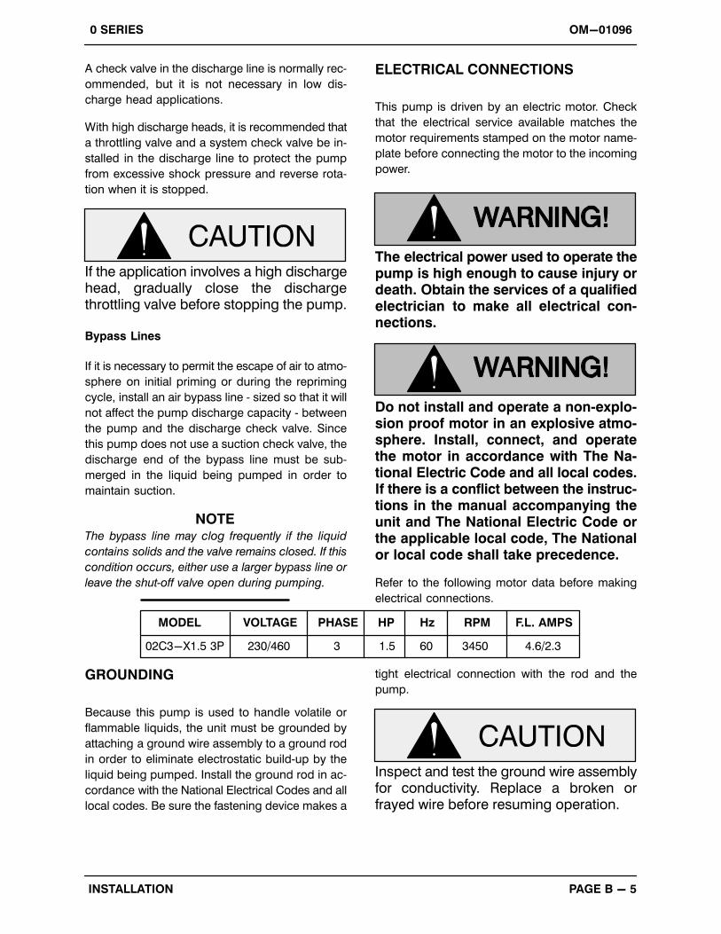
Refer to the following motor data before making
electrical connections.
VOLTAGE PHASE HP Hz RPM F.L. AMPS
230/460 3 60 3450 4.6/2.3
MODEL
02C3-X1.5 3P 1.5
GROUNDING
Because this pump is used to handle volatile or
flammable liquids, the unit must be grounded by
attaching a ground wire assembly to a ground rod
in order to eliminate electrostatic build‐up by the
liquid being pumped. Install the ground rod in ac
cordance with the National Electrical Codes and all
local codes. Be sure the fastening device makes a
tight electrical connection with the rod and the
pump.
Inspect and test the ground wire assemblyfor conductivity. Replace a broken orfrayed wire before resuming operation.
0 SERIES OM-01096
OPERATION PAGE C - 1
OPERATION - SECTION C
Review all SAFETY information in Section A.
Follow the instructions on all tags, labels and
decals attached to the pump.
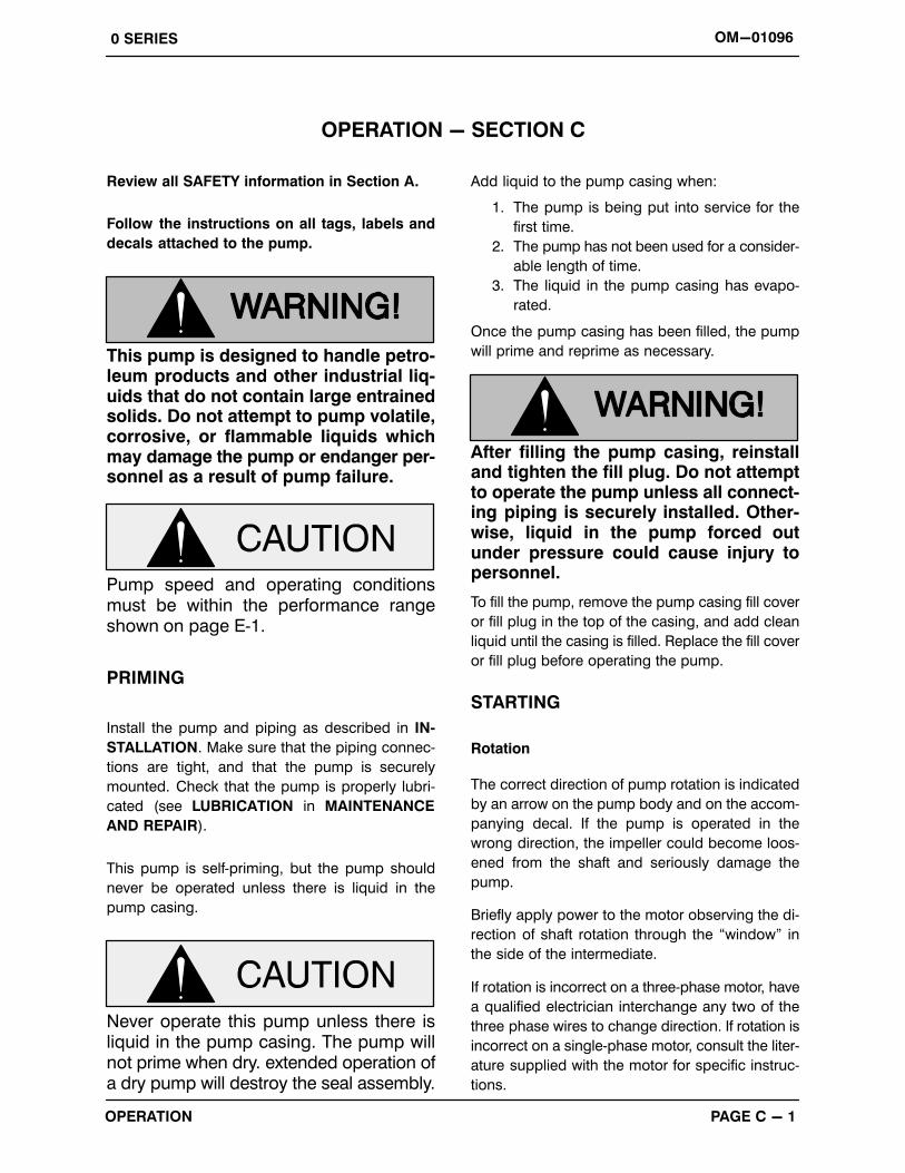
This pump is designed to handle petroleum products and other industrial liquids that do not contain large entrainedsolids. Do not attempt to pump volatile,corrosive, or flammable liquids whichmay damage the pump or endanger personnel as a result of pump failure.
Pump speed and operating conditionsmust be within the performance rangeshown on page E‐1.
PRIMING
Install the pump and piping as described in IN
STALLATION. Make sure that the piping connec
tions are tight, and that the pump is securely
mounted. Check that the pump is properly lubri
cated (see LUBRICATION in MAINTENANCE
AND REPAIR).
This pump is self‐priming, but the pump should
never be operated unless there is liquid in the
pump casing.
Never operate this pump unless there isliquid in the pump casing. The pump willnot prime when dry. extended operation ofa dry pump will destroy the seal assembly.
Add liquid to the pump casing when:
1. The pump is being put into service for the
first time.
2. The pump has not been used for a consider
able length of time.
3. The liquid in the pump casing has evapo
rated.
Once the pump casing has been filled, the pump
will prime and reprime as necessary.
After filling the pump casing, reinstalland tighten the fill plug. Do not attemptto operate the pump unless all connecting piping is securely installed. Otherwise, liquid in the pump forced outunder pressure could cause injury topersonnel.
To fill the pump, remove the pump casing fill cover
or fill plug in the top of the casing, and add clean
liquid until the casing is filled. Replace the fill cover
or fill plug before operating the pump.
STARTING
Rotation
The correct direction of pump rotation is indicated
by an arrow on the pump body and on the accom
panying decal. If the pump is operated in the
wrong direction, the impeller could become loos
ened from the shaft and seriously damage the
pump.
Briefly apply power to the motor observing the di
rection of shaft rotation through the “window” in
the side of the intermediate.
If rotation is incorrect on a three‐phase motor, have
a qualified electrician interchange any two of the
three phase wires to change direction. If rotation is
incorrect on a single‐phase motor, consult the liter
ature supplied with the motor for specific instruc
tions.

0 SERIESOM-01096
OPERATIONPAGE C - 2
OPERATION
Lines With a Bypass
Since this pump does not have a suction check
valve, the discharge end of the bypass line must be
submerged in order to maintain suction.
Close the throttling valve in the discharge line and
open the shut‐off valve in the bypass line so that
the pump will not have to prime against the weight
of the liquid in the discharge line. Start the motor.
When the pump has primed and liquid is flowing
steadily through the bypass line, close the bypass
shut‐off valve and open the discharge throttling
valve.
Lines Without a Bypass
Open all valves in the discharge line and start the
power source. Priming is indicated by a positive
reading on the discharge pressure gauge or by a
quieter operation. The pump may not prime imme
diately because the suction line must first fill with
liquid. If the pump fails to prime within five minutes,
stop it and check the suction line for leaks.
After the pump has been primed, partially close the
discharge line throttling valve in order to fill the line
slowly and guard against excessive shock pres
sure which could damage pipe ends, gaskets,
sprinkler heads, and any other fixtures connected
to the line. When the discharge line is completely
filled, adjust the throttling valve to the required flow
rate.
Do not operate the pump against aclosed discharge throttling valve forlong periods of time. If operated againsta closed discharge throttling valve,pump components will deteriorate, andthe liquid could come to a boil, buildpressure, and cause the pump casing torupture or explode.
Leakage
No leakage should be visible at pump mating sur
faces, or at pump connections or fittings. Keep all
line connections and fittings tight to maintain maxi
mum pump efficiency.
Liquid Temperature And Overheating
The maximum liquid temperature for this pump is
160� F (71� C). Do not apply it at a higher operat
ing temperature.
Overheating can occur if operated with the valves
in the suction or discharge lines closed. Operating
against closed valves could bring the liquid to a
boil, build pressure, and cause the pump to rup
ture or explode. If overheating occurs, stop the
pump and allow it to cool before servicing it. Refill
the pump casing with cool liquid.
Allow an over‐heated pump to completely cool before servicing. Do not remove plates, covers, gauges, or fittingsfrom an over‐heated pump. Liquid within the pump can reach boiling temperatures, and vapor pressure within thepump can cause parts being disengaged to be ejected with great force. After the pump completely cools, drain theliquid from the pump by removing thecasing drain plug. Use caution when removing the plug to prevent injury to personnel from hot liquid.
Strainer Check
If a suction strainer has been shipped with the
pump or installed by the user, check the strainer
regularly, and clean it as necessary. The strainer
should also be checked if pump flow rate begins to
drop. If a vacuum suction gauge has been in
stalled, monitor and record the readings regularly
to detect strainer blockage.
Never introduce air or steam pressure into the
pump casing or piping to remove a blockage. This
could result in personal injury or damage to the
0 SERIES OM-01096
OPERATION PAGE C - 3
equipment. If backflushing is absolutely neces
sary, liquid pressure must be limited to 50% of the
maximum permissible operating pressure shown
on the pump performance curve.
Pump Vacuum Check
With the pump inoperative, install a vacuum gauge
in the system, using pipe dope on the threads.
Block the suction line and start the pump. At oper
ating speed the pump should pull a vacuum of 20
inches (508,0 mm) or more of mercury. If it does
not, check for air leaks in the seal, gasket, or dis
charge valve.
Open the suction line, and read the vacuum gauge
with the pump primed and at operation speed.
Shut off the pump. The vacuum gauge reading will
immediately drop proportionate to static suction
lift, and should then stabilize. If the vacuum reading
falls off rapidly after stabilization, an air leak exists.
Before checking for the source of the leak, check
the point of installation of the vacuum gauge.
STOPPING
After stopping the pump, disconnect the incoming
power to the motor and lock it out to ensure that the
pump will remain inoperative.
Do not operate the pump against aclosed discharge throttling valve forlong periods of time. If operated againsta closed discharge throttling valve,pump components will deteriorate, andthe liquid could come to a boil, buildpressure, and cause the pump casing torupture or explode.
Cold Weather Preservation
In below freezing conditions, drain the pump to
prevent damage from freezing. Also, clean out any
solids by flushing with a hose. Operate the pump
for approximately one minute; this will remove any
remaining liquid that could freeze the pump rotat
ing parts. If the pump will be idle for more than a
few hours, drain the pump, and flush it thoroughly
with clean liquid. Operate the pump during the
draining process.
0 SERIES OM-01096
TROUBLESHOOTING PAGE D - 1
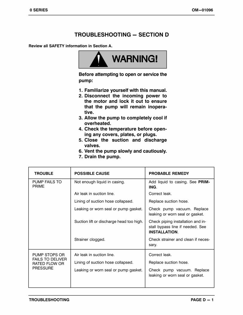
TROUBLESHOOTING - SECTION D
Review all SAFETY information in Section A.
Before attempting to open or service the
pump:
1. Familiarize yourself with this manual.2. Disconnect the incoming power to
the motor and lock it out to ensurethat the pump will remain inoperative.
3. Allow the pump to completely cool ifoverheated.
4. Check the temperature before opening any covers, plates, or plugs.
5. Close the suction and dischargevalves.
6. Vent the pump slowly and cautiously.7. Drain the pump.
TROUBLE POSSIBLE CAUSE PROBABLE REMEDY
PUMP FAILS TOPRIME
Air leak in suction line.
Lining of suction hose collapsed.
Correct leak.
Replace suction hose.
Leaking or worn seal or pump gasket. Check pump vacuum. Replace
leaking or worn seal or gasket.
Suction lift or discharge head too high. Check piping installation and in
stall bypass line if needed. See
INSTALLATION.
Strainer clogged. Check strainer and clean if neces
sary.
Not enough liquid in casing. Add liquid to casing. See PRIM
ING.
PUMP STOPS ORFAILS TO DELIVERRATED FLOW ORPRESSURE
Air leak in suction line.
Lining of suction hose collapsed.
Correct leak.
Replace suction hose.
Leaking or worn seal or pump gasket. Check pump vacuum. Replace
leaking or worn seal or gasket.

OM-01096 0 SERIES
TROUBLESHOOTINGPAGE D - 2
TROUBLE POSSIBLE CAUSE PROBABLE REMEDY
PUMP REQUIRESTOO MUCHPOWER
PUMP CLOGSFREQUENTLY
Impeller or other wearing parts worn
or damaged.
Replace worn or damaged parts.
Check that impeller is properly
centered and rotates freely.
Impeller clogged. Free impeller of debris.
Discharge head too low. Adjust discharge valve.
Liquid solution too thick. Dilute if possible.
Liquid solution too thick. Dilute if possible.
Discharge flow too slow. Open discharge valve fully to in
crease flow rate, and run power
source at maximum governed
speed.
PUMP STOPS ORFAILS TO DELIVERRATED FLOW ORPRESSURE (cont.)
Strainer clogged. Check strainer and clean if neces
sary.
Suction intake not submerged at
proper level or sump too small.
Check installation and correct sub
mergence as needed.
Suction lift or discharge head too high. Check piping installation and install
bypass line if needed. See INSTAL
LATION.
Low or incorrect voltage. Measure control box voltage, both
when pump is running and when
shut off.
No voltage at line side of circuit
breaker.
Check power source for blown fuse,
open circuit breaker or control box,
broken lead, or loose connection.
EXCESSIVE NOISE
Impeller clogged or damaged.
Pump or drive not securely mounted.
Pumping entrained air. Locate and eliminate source of air
bubble.
Secure mounting hardware.
Clean out debris; replace dam
aged parts.
Cavitation in pump. Reduce suction lift and/or friction
losses in suction line. Record vac
uum and pressure gauge readings
and consult local representative or
factory.
Pump running backwards. Check direction of rotation and cor
rect by interchanging any two motor
leads at control box. (See Pump Ro
tation, Section C).
0 SERIES OM-01096
TROUBLESHOOTING PAGE D - 3
PREVENTIVE MAINTENANCE
Since pump applications are seldom identical, and
pump wear is directly affected by such things as
the abrasive qualities, pressure and temperature
of the liquid being pumped, this section is intended
only to provide general recommendations and
practices for preventive maintenance. Regardless
of the application however, following a routine pre
ventive maintenance schedule will help assure
trouble‐free performance and long life from your
Gorman‐Rupp pump. For specific questions con
cerning your application, contact your Gorman‐
Rupp distributor or the Gorman‐Rupp Company.
Record keeping is an essential component of a
good preventive maintenance program. Changes
in suction and discharge gauge readings (if so
equipped) between regularly scheduled inspec
tions can indicate problems that can be corrected
before system damage or catastrophic failure oc
curs. The appearance of wearing parts should also
be documented at each inspection for comparison
as well. Also, if records indicate that a certain part
(such as the seal) fails at approximately the same
duty cycle, the part can be checked and replaced
before failure occurs, reducing unscheduled down
time.
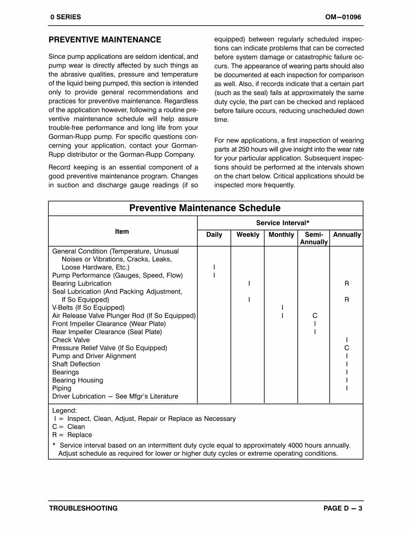
For new applications, a first inspection of wearing
parts at 250 hours will give insight into the wear rate
for your particular application. Subsequent inspec
tions should be performed at the intervals shown
on the chart below. Critical applications should be
inspected more frequently.
General Condition (Temperature, UnusualNoises or Vibrations, Cracks, Leaks,
Loose Hardware, Etc.) I
Pump Performance (Gauges, Speed, Flow) I
Bearing Lubrication I R
Seal Lubrication (And Packing Adjustment,
If So Equipped) I RV‐Belts (If So Equipped) I
Air Release Valve Plunger Rod (If So Equipped) I C
Front Impeller Clearance (Wear Plate) I
Rear Impeller Clearance (Seal Plate) I
Check Valve IPressure Relief Valve (If So Equipped) C
Pump and Driver Alignment I
Shaft Deflection I
Bearings I
Bearing Housing IPiping I
Driver Lubrication - See Mfgr's Literature
Legend:
I = Inspect, Clean, Adjust, Repair or Replace as Necessary
C = Clean
R = Replace
* Service interval based on an intermittent duty cycle equal to approximately 4000 hours annually.
Adjust schedule as required for lower or higher duty cycles or extreme operating conditions.
Preventive Maintenance Schedule
Item Daily Weekly Monthly Semi‐Annually
Annually
Service Interval*
OM-010960 SERIES
MAINTENANCE & REPAIR PAGE E - 1
PUMP MAINTENANCE AND REPAIR - SECTION E
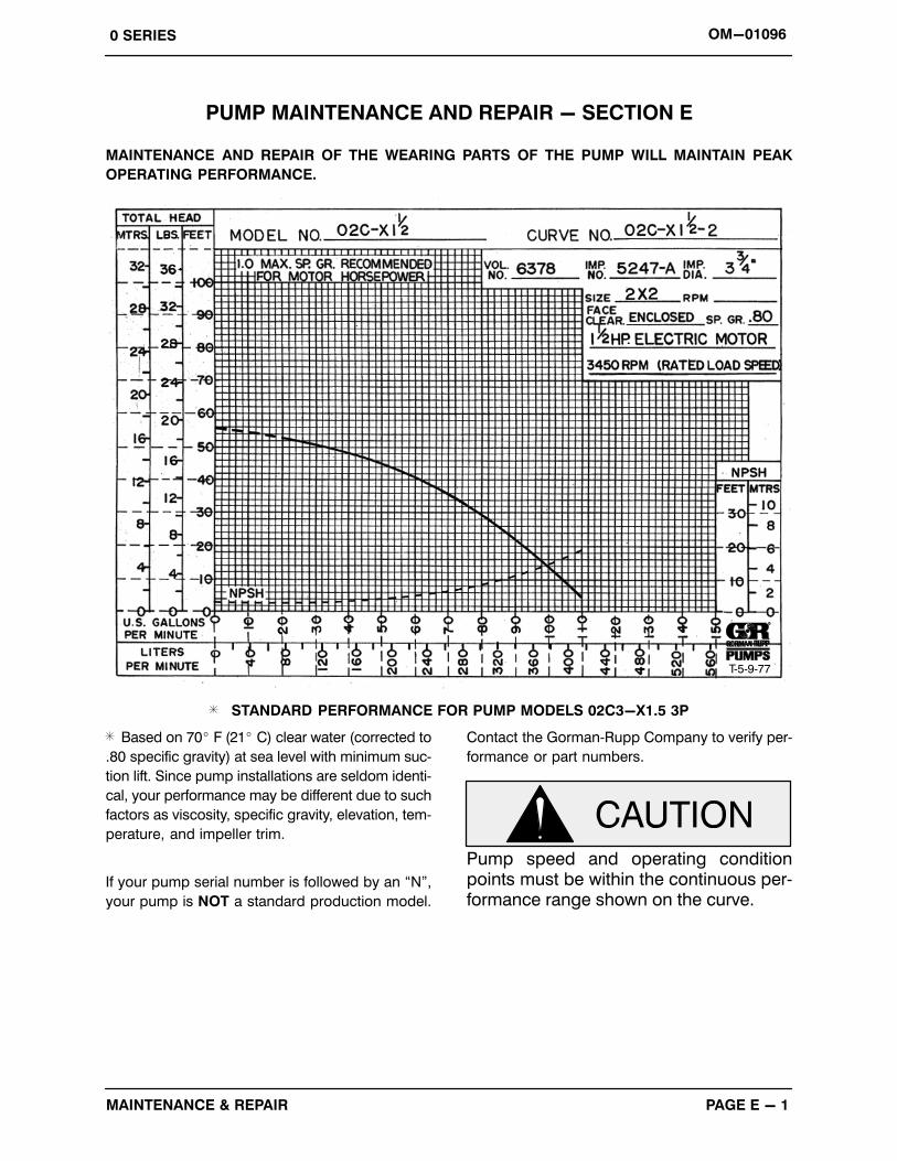
MAINTENANCE AND REPAIR OF THE WEARING PARTS OF THE PUMP WILL MAINTAIN PEAK
OPERATING PERFORMANCE.
T‐5‐9‐77
STANDARD PERFORMANCE FOR PUMP MODELS 02C3-X1.5 3P
Based on 70� F (21� C) clear water (corrected to
.80 specific gravity) at sea level with minimum suc
tion lift. Since pump installations are seldom identi
cal, your performance may be different due to such
factors as viscosity, specific gravity, elevation, tem
perature, and impeller trim.
If your pump serial number is followed by an “N”,
your pump is NOT a standard production model.
Contact the Gorman‐Rupp Company to verify per
formance or part numbers.
Pump speed and operating conditionpoints must be within the continuous performance range shown on the curve.
OM-01096 0 SERIES
MAINTENANCE & REPAIRPAGE E - 2
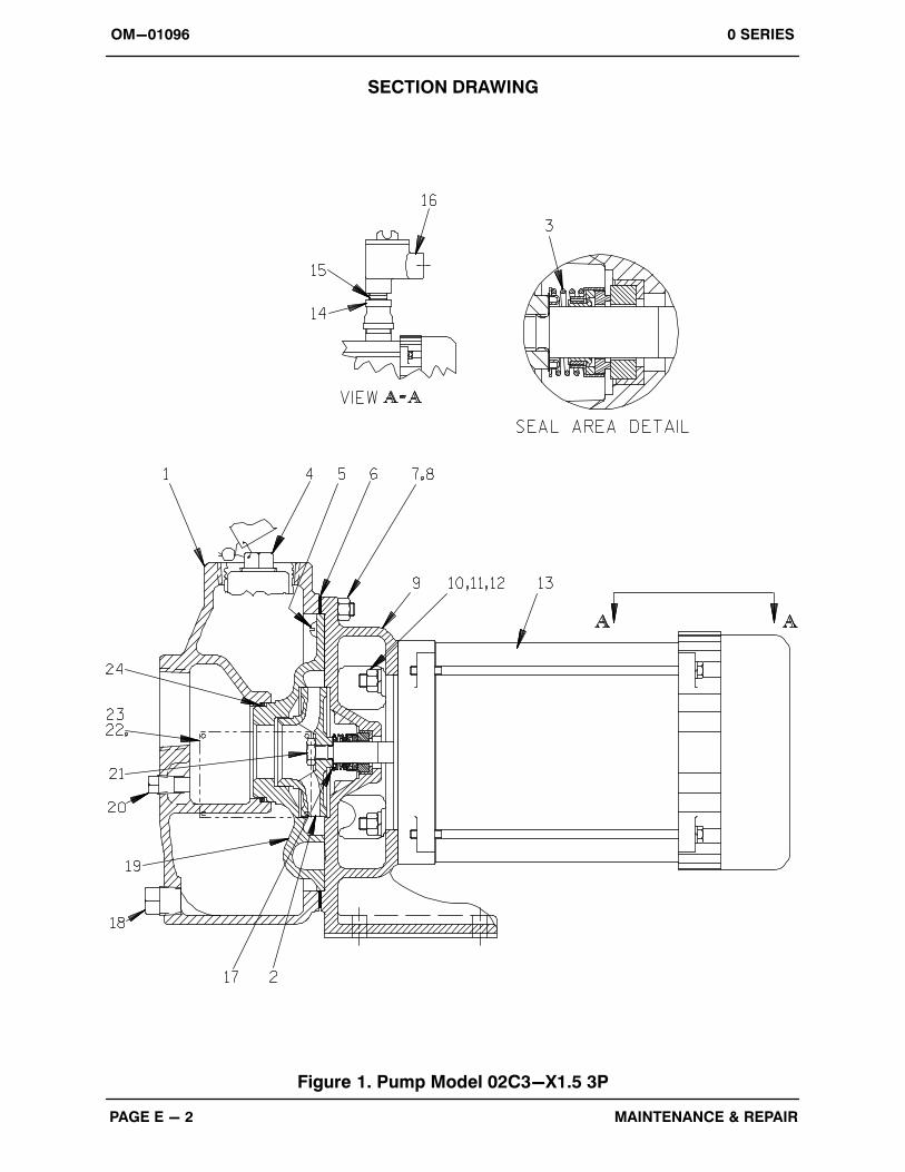
SECTION DRAWING
PARTS PAGE
Figure 1. Pump Model 02C3-X1.5 3P
OM-010960 SERIES
MAINTENANCE & REPAIR PAGE E - 3
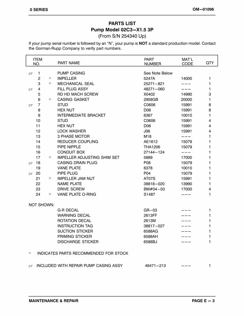
PARTS LIST
Pump Model 02C3-X1.5 3P
(From S/N 254340 Up)
If your pump serial number is followed by an “N”, your pump is NOT a standard production model. Contact
the Gorman‐Rupp Company to verify part numbers.
ITEM NO. PART NAME
PART NUMBER
MAT'LCODE QTY
� 1 PUMP CASING See Note Below
2 IMPELLER 5247A 14000 1
3 MECHANICAL SEAL 25271-821 --- 1
� 4 FILL PLUG ASSY 48271-060 --- 1
5 RD HD MACH SCREW X0402 14990 3
6 CASING GASKET 2958GB 20000 1
� 7 STUD C0606 15991 8
8 HEX NUT D06 15991 8
9 INTERMEDIATE BRACKET 6367 10010 1
10 STUD C0606 15991 4
11 HEX NUT D06 15991 4
12 LOCK WASHER J06 15991 4
13 3 PHASE MOTOR M18 --- 1
14 REDUCER COUPLING AE1612 15079 1
15 PIPE NIPPLE THA1206 15079 1
16 CONDUIT BOX 27144-124 --- 1
17 IMPELLER ADJUSTING SHIM SET 5889 17000 1
� 18 CASING DRAIN PLUG P08 15079 1
19 VANE PLATE 6378 10010 1
� 20 PIPE PLUG P04 15079 1
21 IMPELLER JAM NUT AT07S 15991 1
22 NAME PLATE 38818-020 13990 1
23 DRIVE SCREW BM#04-03 17000 4
24 VANE PLATE O‐RING S1487 --- 1
NOT SHOWN:
G‐R DECAL GR-03 --- 1
WARNING DECAL 2613FF --- 1
ROTATION DECAL 2613M --- 1
INSTRUCTION TAG 38817-027 --- 1
SUCTION STICKER 6588AG --- 1
PRIMING STICKER 6588AH --- 1
DISCHARGE STICKER 6588BJ --- 1
INDICATES PARTS RECOMMENDED FOR STOCK
� INCLUDED WITH REPAIR PUMP CASING ASSY 46471-213 --- 1
OM-01096 0 SERIES
MAINTENANCE & REPAIRPAGE E - 4
PUMP AND SEAL DISASSEMBLY
AND REASSEMBLY
Review all SAFETY information in Section A.
Follow the instructions on all tags, label and decals
attached to the pump.
This pump requires little service due to its rugged,
minimum‐maintenance design. However, if it be
comes necessary to inspect or replace the wearing
parts, follow these instructions which are keyed to
the sectional view (see Figure 1) and the accompa
nying parts list.
This manual will alert personnel to known proce
dures which require special attention, to those
which could damage equipment, and to those
which could be dangerous to personnel. However,
this manual cannot possibly anticipate and provide
detailed precautions for every situation that might
occur during maintenance of the unit. Therefore, it
is the responsibility of the owner/maintenance per
sonnel to ensure that only safe, established main
tenance procedures are used, and that any proce
dures not addressed in this manual are performed
only after establishing that neither personal safety
nor pump integrity are compromised by such prac
tices.
Before attempting to service the pump, disconnect
the incoming power to the motor and lock it out to
ensure that the pump will remain inoperative.
Close all valves in the suction and discharge lines.
For motor disassembly and repair, consult the liter
ature supplied with the motor, or contact your local
motor representative.
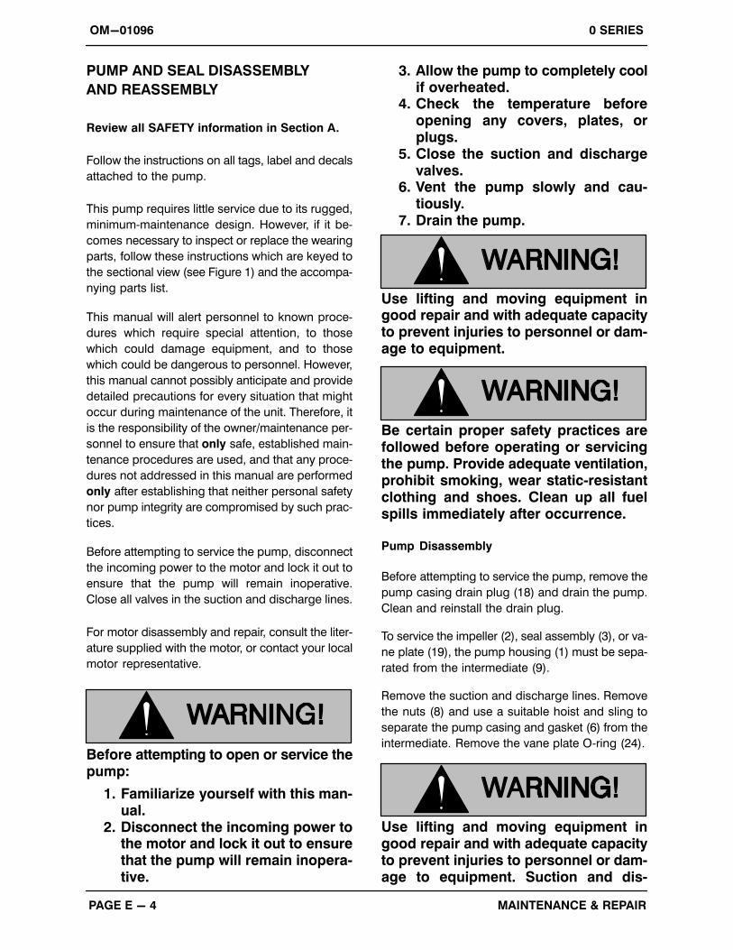
Before attempting to open or service thepump:
1. Familiarize yourself with this manual.
2. Disconnect the incoming power tothe motor and lock it out to ensurethat the pump will remain inoperative.
3. Allow the pump to completely coolif overheated.
4. Check the temperature beforeopening any covers, plates, orplugs.
5. Close the suction and dischargevalves.
6. Vent the pump slowly and cautiously.
7. Drain the pump.
Use lifting and moving equipment ingood repair and with adequate capacityto prevent injuries to personnel or damage to equipment.
Be certain proper safety practices arefollowed before operating or servicingthe pump. Provide adequate ventilation,prohibit smoking, wear static‐resistantclothing and shoes. Clean up all fuelspills immediately after occurrence.
Pump Disassembly
Before attempting to service the pump, remove the
pump casing drain plug (18) and drain the pump.
Clean and reinstall the drain plug.
To service the impeller (2), seal assembly (3), or va
ne plate (19), the pump housing (1) must be sepa
rated from the intermediate (9).
Remove the suction and discharge lines. Remove
the nuts (8) and use a suitable hoist and sling to
separate the pump casing and gasket (6) from the
intermediate. Remove the vane plate O‐ring (24).
Use lifting and moving equipment ingood repair and with adequate capacityto prevent injuries to personnel or damage to equipment. Suction and dis
OM-010960 SERIES
MAINTENANCE & REPAIR PAGE E - 5
charge hoses and piping must be removed from the pump before lifting.
Impeller Removal
For access to the impeller (2), disengage the
screws (5) and remove the vane plate (19). Immo
bilize the impeller by inserting a bar between the
impeller vanes, being careful not to damage the
vanes. Disengage the impeller nut (21).
Immobilize the motor shaft by inserting a large flat
head screwdriver into the slot in the end of the shaft
in the front end of the motor.
Unscrew the impeller from the shaft. Use caution
when removing the impeller; tension on the seal
spring will be released as the impeller is removed.
Remove the impeller adjusting shims (17). Tie and
tag the shims or measure and record their thick
ness for ease of reassembly.
Seal Removal and Disassembly
Remove the spring retainer and spring. Apply oil to
the shaft and work it up under the rubber bellows.
Slide the rotating portion of the seal off the shaft.
Remove the hardware (11 and 12) securing the in
termediate (9) to the motor (13). Slide the inter
mediate off the shaft and use a suitably sized dowel
to press the seal stationary element and seat out of
the intermediate from the back side.
Seal Reassembly and Installation
Clean the seal cavity and shaft with a cloth soaked
in fresh cleaning solvent.
Most cleaning solvents are toxic andflammable. Use them only in a well ventilated area free from excessive heat,sparks, and flame. Read and follow allprecautions printed on solvent containers.
The seal is not normally reused because wear pat
terns on the finished faces cannot be realigned
during reassembly. This could result in premature
failure. If necessary to reuse an old seal in an emer
gency, carefully wash all metallic parts in fresh
cleaning solvent and allow to dry thoroughly.
Handle the seal parts with extreme care to prevent
damage. Be careful not to contaminate precision
finished faces; even fingerprints on the faces can
shorten seal life. If necessary, clean the faces with a
non‐oil based solvent and a clean, lint‐free tissue.
Wipe lightly in a concentric pattern to avoid
scratching the faces.
Inspect the seal components for wear, scoring,
grooves, and other damage that might cause leak
age. If any components are worn, replace the com
plete seal; never mix old and new seal parts.
If a replacement seal is being used, remove it from
the container and inspect the precision finished
faces to ensure that they are free of any foreign
matter.
To ease installation of the seal, lubricate the bel
lows with water or a very small amount of light lu
bricating oil, and apply a drop of light lubricating oil
on the finished faces. Assemble the seal as follows
(see Figure 2).
OM-01096 0 SERIES
MAINTENANCE & REPAIRPAGE E - 6
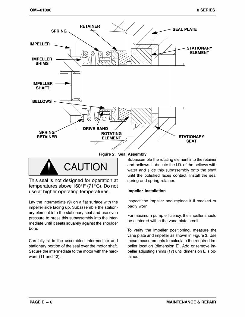
SEAL PLATE
IMPELLERSHAFT
STATIONARYSEAT
ROTATINGELEMENT
DRIVE BAND
BELLOWS
IMPELLERSHIMS
IMPELLER
SPRING
RETAINER
STATIONARYELEMENT
SPRINGRETAINER
Figure 2. Seal Assembly
This seal is not designed for operation attemperatures above 160�F (71�C). Do notuse at higher operating temperatures.
Lay the intermediate (9) on a flat surface with the
impeller side facing up. Subassemble the station
ary element into the stationary seat and use even
pressure to press this subassembly into the inter
mediate until it seats squarely against the shoulder
bore.
Carefully slide the assembled intermediate and
stationary portion of the seal over the motor shaft.
Secure the intermediate to the motor with the hard
ware (11 and 12).
Subassemble the rotating element into the retainer
and bellows. Lubricate the I.D. of the bellows with
water and slide this subassembly onto the shaft
until the polished faces contact. Install the seal
spring and spring retainer.
Impeller Installation
Inspect the impeller and replace it if cracked or
badly worn.
For maximum pump efficiency, the impeller should
be centered within the vane plate scroll.
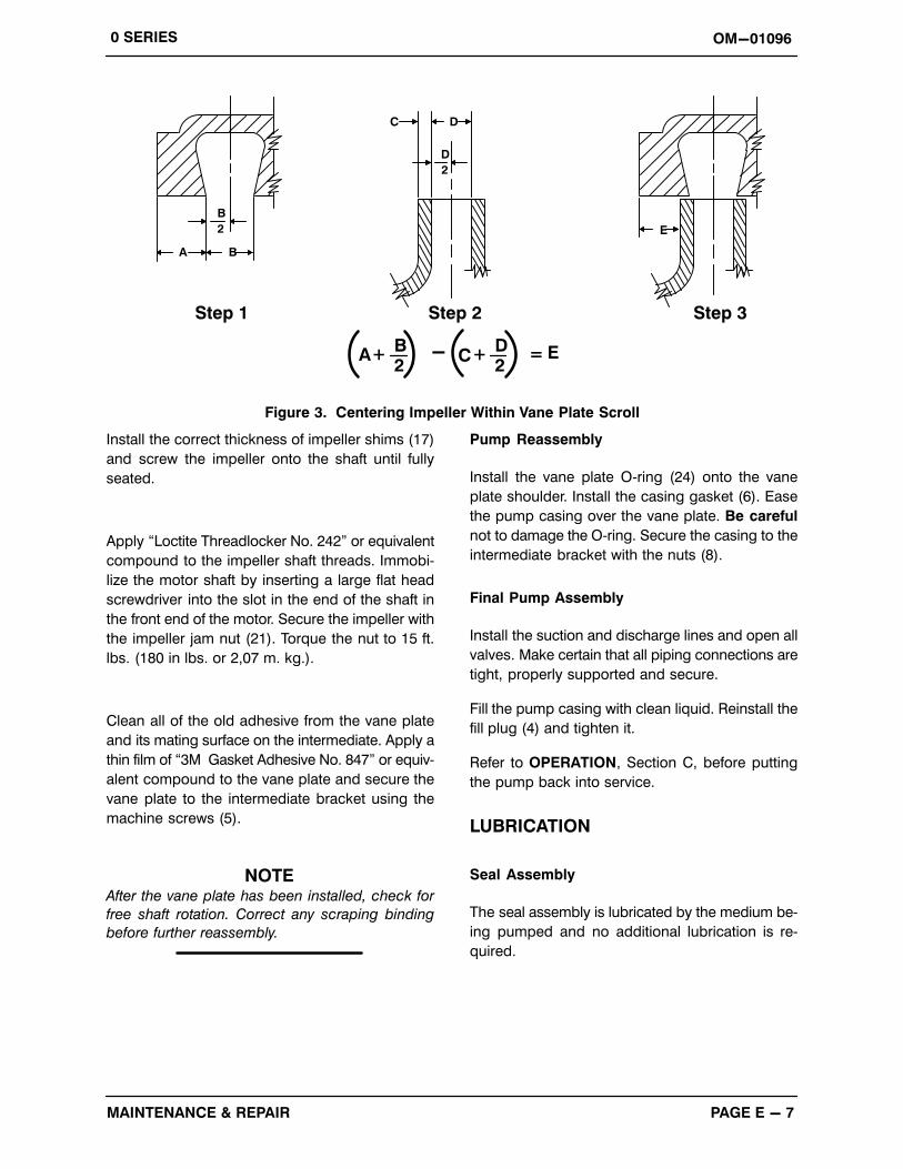
To verify the impeller positioning, measure the
vane plate and impeller as shown in Figure 3. Use
these measurements to calculate the required im
peller location (dimension E). Add or remove im
peller adjusting shims (17) until dimension E is ob
tained.
OM-010960 SERIES
MAINTENANCE & REPAIR PAGE E - 7
D
B
2
A B
2
C D
E
Step 2Step 1 Step 3
A+B2
C+D2
E=-
Figure 3. Centering Impeller Within Vane Plate Scroll
Install the correct thickness of impeller shims (17)
and screw the impeller onto the shaft until fully
seated.
Apply “Loctite Threadlocker No. 242” or equivalent
compound to the impeller shaft threads. Immobi
lize the motor shaft by inserting a large flat head
screwdriver into the slot in the end of the shaft in
the front end of the motor. Secure the impeller with
the impeller jam nut (21). Torque the nut to 15 ft.
lbs. (180 in lbs. or 2,07 m. kg.).
Clean all of the old adhesive from the vane plate
and its mating surface on the intermediate. Apply a
thin film of “3M Gasket Adhesive No. 847” or equiv
alent compound to the vane plate and secure the
vane plate to the intermediate bracket using the
machine screws (5).
NOTEAfter the vane plate has been installed, check for
free shaft rotation. Correct any scraping binding
before further reassembly.
Pump Reassembly
Install the vane plate O‐ring (24) onto the vane
plate shoulder. Install the casing gasket (6). Ease
the pump casing over the vane plate. Be careful
not to damage the O‐ring. Secure the casing to the
intermediate bracket with the nuts (8).
Final Pump Assembly
Install the suction and discharge lines and open all
valves. Make certain that all piping connections are
tight, properly supported and secure.
Fill the pump casing with clean liquid. Reinstall the
fill plug (4) and tighten it.
Refer to OPERATION, Section C, before putting
the pump back into service.
LUBRICATION
Seal Assembly
The seal assembly is lubricated by the medium be
ing pumped and no additional lubrication is re
quired.

For U.S. and International Warranty Information,Please Visit www.grpumps.com/warranty
or call:U.S.: 419-755-1280
International: +1-419-755-1352
For Canadian Warranty Information,Please Visit www.grcanada.com/warranty
or call:519-631-2870
THE GORMAN‐RUPP COMPANY � MANSFIELD, OHIOGORMAN‐RUPP OF CANADA LIMITED � ST. THOMAS, ONTARIO, CANADA