installation of shallow bore rn 15704 ross · pdf filecontractor had attempted a caisson...
TRANSCRIPT
Technical Report WRA90010
Viewed at 03:02:33 on 18/02/2010 Page 1 of 40.
I I I I I I I I I I I I I I I I I I I I
prepared by:
Eric Rooke
INSTALLATION OF SHALLOW BORE RN 15704
AT ROSS RIVER HOMESTEAD
TOURIST RESORT
Senior Hydrogeologist Water Resources Branch
January 1990
Technical Report WRA90010
Viewed at 03:02:33 on 18/02/2010 Page 2 of 40.
I I I I I I I I I I I I I I I I I I I I
1. INTRODUCTION 2. PHYSIOGRAPHY, GEOLOGY AND HYDROGEOLOGY
3. CONCRETE WELL: ATTEMPTED COl-lPLETION
4. SURVEY OF RIVER ALLUVIUl-l
5. SHALLOW BORE INSTALLATION
6. PUMPING TEST
6.1 Operation and Field Data Collection
6.2 Analysis
6.3 Evaluation of the Results
CONTENTS
6.3.1 Maximum Production Yield of Bore
RN 15704
6.3.2 Screen Entrance velocity
7. ESTIMATED LONG TERl-l SAFE YIELD
7.1 Peak Demand from Bore RN 15704
7.2 Aquifer Depletion at the Safe Yield
7.3 Conclusion
8. WATER QUALITY
9. CONCLUSIONS
10. RECOMMENDATIONS
LIST OF FIGURES
1. LOCATION ~IAP
2. SITE PLAN
3. BOREHOLE CONSTRUCTION DETAILS
Technical Report WRA90010
Viewed at 03:02:33 on 18/02/2010 Page 3 of 40.
I I I I I I I I I I I I I I I I I I I I
APPENDICES
A. ALLUVIUM SAMPLING TRAVERSE ACROSS ROSS RIVER
B. RESULTS OF QUALITY ANALYSIS ON STANDING WATER
SAMPLE FROM WELL RN 3396 C.l pmlPING TEST DATA AND JACOB'S ANALYSIS OF DRAWDOWN
GRAPH C.2 CALCULATION OF WELL EFFICIENCY C.3 ~1AXn!uM PRODUCTION YIELD OF BORE RN 15704
C.4 CALCULATION OF SCREEN ENTRANCE VELOCITY
ABBREVIATIONS
AHD Australian Height Datum
L/s litres per second
kL kiloE tres
1 ML - 1000 kL
mq/L milligrams per litre (parts per million)
RN registered number of bore
SWL standing water level (below ground)
DISTRIBUTION
ROSS River Homestead Tourist Re'sort 2
Water Resources Branch Library Alice Springs 3
Water Library Darwin 1
principal Engineer Groundwater 1
bt~r 1
Technical Report WRA90010
Viewed at 03:02:33 on 18/02/2010 Page 4 of 40.
I I I I I I I I I I I I I I I I I I I I
1. INTRODUCTION
The management of Ross River Homestead tourist resort
engaged the water Resources Branch, PAWA, Alice springs
to provide a new water supply source works to replace
their existing dug shallow well (Registered Number
RN 3396) located in the bed of the Ross River. This
timber-lined well is subject to surface water
contamination and also to periodic burial whenever the
river floods. It has been condemned as posing a health
risk from bacterial pollution.
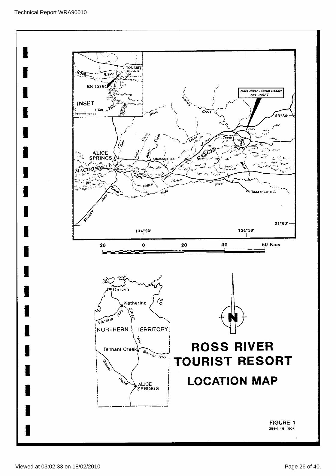
Ross River Homestead is situated approximately 85 km due
east of Alice Springs on the Ross River Highway (see
Figure 1). It operates as a tourist resort with
chalets, a camp and a caravan site. It has restaurant,
bar and swimming pool facilities. Therefore, it
requires a wholesome, potable supply of water. The
estimated water consumption is of the order of 180
kL/day. However, there are plans to expand the resort
and the water demand should increase accordingly.
After discussion with the management it was agreed that
an attempt should be made to complete the sinking of a
partially installed concrete well. The construction of
this well in the bed of the Ross River had been
undertaken
contractor.
originally by a private engineering
The objectives of this project were two-fold, namely:-
to increase the yield available from the shallow
alluvial aquifer commensurate with a projected
increase in water demand for a planned expansion of
the tourist facilities, and
Technical Report WRA90010
Viewed at 03:02:33 on 18/02/2010 Page 5 of 40.
I I I I I I I I I I I I I I I I I I I I
to improve the bacterial quality of the water
supply to provide a wholesome, potable water which
meets with standard health requirements.
Technical Report WRA90010
Viewed at 03:02:33 on 18/02/2010 Page 6 of 40.
I I I I I I I I I I I I I I I I I I I I
2. PHYSIOGRAPHY, GEOLOGY AND HYDROGEOLOGY
Ross River Homestead is situated on the outside
(north-east) bank of a bend in the Ross River at an
elevation of 500 m AHD. At this locality the Ross
River, which is ephemeral, turns sharply and passes
southwards through the eastern MacDonnell Ranges to form
an un-named gorge. The existing well RN 3396, abandoned
concrete well (refer to Section 3) and the newly
installed shallow bore (Section 5) lie across the bend
in the river where its alluvial bed is near its maximum
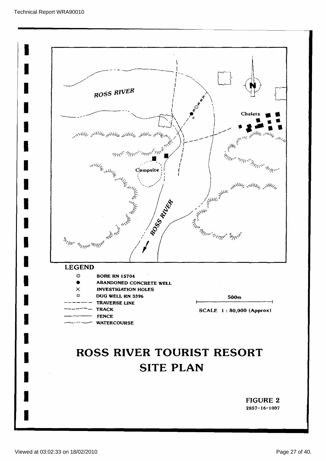
width of approximately 220 m. Their locations are shown
on Figure 2. There is a 750 m long expanse of re-worked
alluvial loose coarse sand, gravel and cobble - size
material upstream of the gorge. Immediately north of
the Homestead two southerly flowing tributaries enter
the Ross River where the outside bend is eroding the
north bank. This expanse of alluvial gravel continues
upstream for about another 750 m.
upstream
parallels
of the aforementioned bend, the Ross River
the strike of the northern limb of the Ross
River Syncline before it turns south near the nose of
this syncline and cuts through a succession of steeply -
dipping Lower Proterozoic to early Cambrian dolomites,
sandstones and siltstones of the Amadeus Basin
sedimentary rock sequence. The bedrock underlying the
Ross River Homestead is a more recessive sandstone
(Pertatataka Formation) than the dolomites and siliceous
sandstones which form the strike ridges. Two boreholes
(RN 3397 and RN 3398) were drilled during 1957 at a
location about 10 m from the north bank, at a distance
of 60 m apart, probably into the Pertatataka Formation.
Technical Report WRA90010
Viewed at 03:02:33 on 18/02/2010 Page 7 of 40.
I I I I I I I I I I I I I I I I I I I I
However they yielded only a maximum of 2.5 Lis with a
fair water quality (total dissolved solids of 1600 mglL and very hard). A third borehole (RN 3396) constructed
only 6 m into the Ross River bed (and perhaps 60 m to
the south of RN 3398) produced better quality water.
Its static water level (SWL) was 5 m below ground level
(b.g.!.) but it was not pump tested. The former two
boreholes are abandoned, whilst RN 3396 presently
supplies the resort.
Because of financial considerations and the confidence that a suitable reserve of good quality groundwater
saturates the alluvium in the Ross River the option of
drilling deep boreholes was disregarded. Instead,
attention was restricted to exploiting the shallow
alluvial aquifer.
Technical Report WRA90010
Viewed at 03:02:33 on 18/02/2010 Page 8 of 40.
I I I I I I I I I I I I I I I I I I I I
3. CONCRETE WELL: ATTEMPTED COMPLETION
The partially installed concrete well consisted of five
lengths of 'Humes' concrete pipe, the lower four lengths
of which had been perforated with 10 mm holes and the
uppermost length had been left intact. The pipes'
diameter was 1.22 m ID with a wall thickness of 70 rom
and a length of 1.22 m each. previously a private
contractor had attempted a caisson construction method
using a bucket on a rope to excavate the soil from
within the pipe so that the pipe would sink under its
own weight. upon reaching the water table, progress
slowed to an unacceptable pace owing to caving by saturated sand. Consequently, the well was abandoned,
approximately 1.5 m proud of ground level with only the
bottom 1 m of perforated pipe below the water table.
The test pump crew of the water Resources Branch
(WRB) PAWA attempted to sink the concrete well a further 2 m or so into the river bed using an air-jetting
technique. (This technique not only ejects loose sediments from an annulus, but mobilises the saturated
sediments thus lowering their viscosity and density so
that the concrete pipes should sink more easily). A
'duo-pipe' jetting tool was used in an attempt to jet
the well down to its final depth. It consisted of a 200
rom NB steel casing about 6 m long with a tee at the top
end to direct the jetted sediment
A longer-length of 50 mm NB GI
clear from the hole.
pipe was telescoped
through the steel casing with its top end connected to
an air compressor by a flexible hose. The whole
assembly was suspended by 'sand-lines' using a truck-
mounted t Smeal' crane. A 350 CFM
Technical Report WRA90010
Viewed at 03:02:33 on 18/02/2010 Page 9 of 40.
I I I I I I I I I I I I I I I I I I I I
compressor was used to introduce compressed air down the
GI pipe. The duo-pipe was then worked around the inner
circumference of the concrete pipe. Unfortunately,
because of the large diameter of the concrete pipes the
jetting could not cope with the areal extent of the
sediments, even with the compressor at maximum output.
Instead. the air escaped around the edges of the pipe
and caused slumping around the outside of the concrete
pipe which instigated upwelling of the sediment inside
the pipe. As a resul t, al though the Humes pipe sunk a
little (at a rate of about 0.1 m per hour), effectively
no extra depth was made below the water table.
After several hOUTS the attempt to sink the well was
aborted. Upon informing the Maintenance Manager of the
lack of progress it was mutually agreed to conduct a
soil survey across the river bed as detailed in WRB's
proposal.
Technical Report WRA90010
Viewed at 03:02:33 on 18/02/2010 Page 10 of 40.
I I I I I I I I I I I I I I I I I I I I
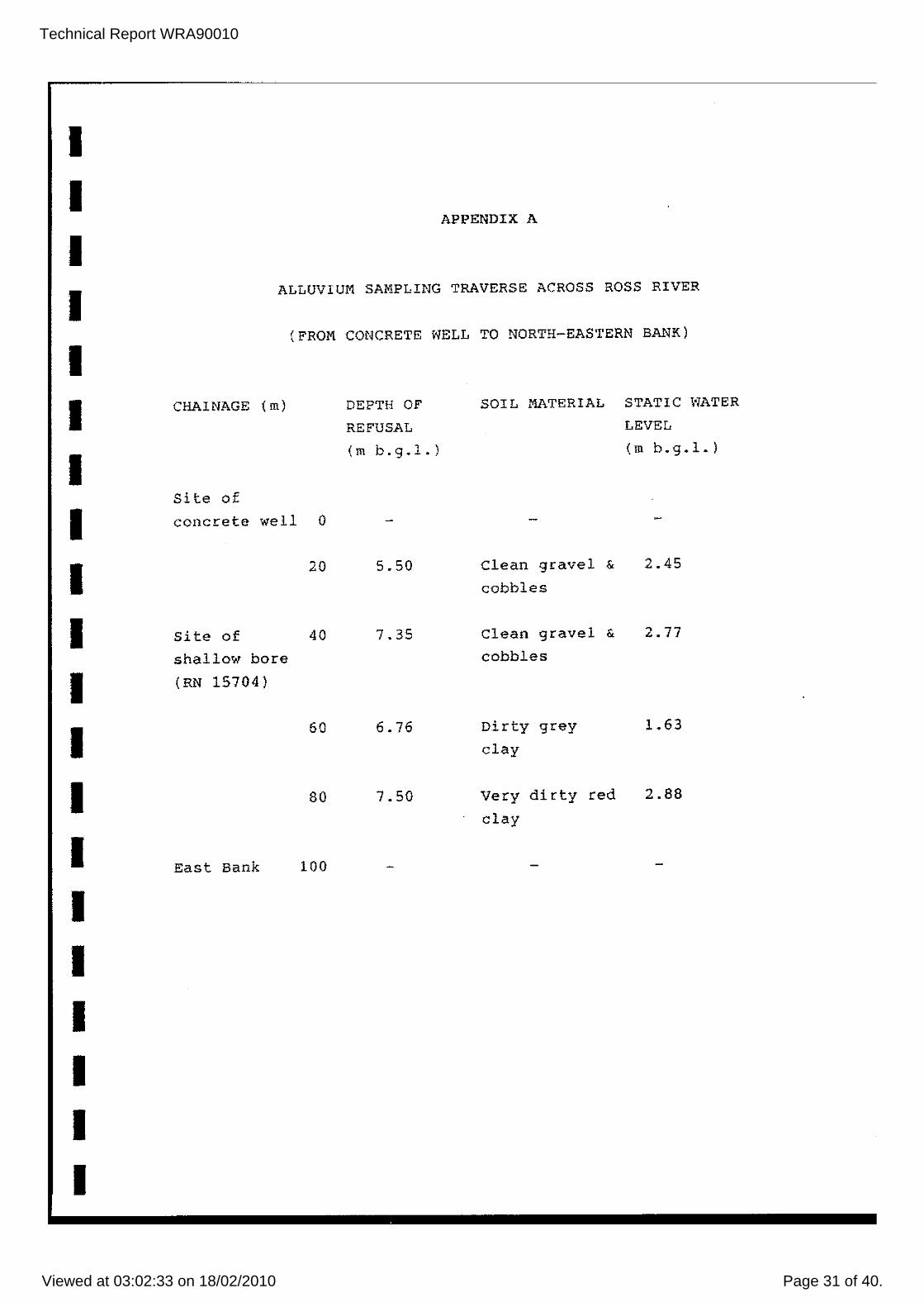
4. SURVEY OF RIVER ALLUVIUM
A survey to investigate the total depth, grain size and
saturated thickness of the alluvium was undertaken by a
travese across the bed of the Ross Rive r, offset from
the site of the aborted concrete well along a magnetic
bearing of 030°. Holes were put down at 20 m intervals
using a medium diameter (100 mm) 'duo-tube' air-jetting
tool. The! r locations are shown in Figuee 2 and the
results of the survey are summarised as Appendix A. The
deepest alluvium was penetrated 40 m to the north-east
of the conceete well. At this site air-jetting ejected
coarse sand grading to gravel at depth; refusal occurred
at 7.55 m b.g.l. owing to numerous cobbles which could
not be lifted and bedrock was not reached. The water
table was encountered at 2.77 m b.g.1. Because of the
large saturated thickness of the alluvium at this site,
it was decided to install a shallow bo!:e here without
recourse to further survey work along the river bed.
Technical Report WRA90010
Viewed at 03:02:33 on 18/02/2010 Page 11 of 40.
I I I I I I I I I I I I I I I I I I I I
5. SHALLOW BORE INSTALLATION
A 6.3 m length of 250 mm NB steel casing .las jetted into
the ground using the smaller- 'duo-tube' jetting tool.
The bottom of the casing was serrated to give a cutting
edge. Another 3.2 m of 250 mm NB casing was welded onto
the top of the sunken pipe. Between 7.5 m and 9 m
water-worn, well-rounded, platy cobbles of siltstone and
sandstone and gravel were ejected. Below 9 m a muddy
water return indicated the presence of a brown grey clay
which was possibly extremely weathered bedrock. The
jetting operation took only two hours to complete and it
terminated just below 9 m b.g.l. A 1.5 m length of 219
mm OD stainless steel well screen was butt-welded to two
lengths of 200 mm NB steel casing of lengths 1.86 m and
6.45 m respectively. A 0.3 m long sump was welded onto
the bottom of the screen to collect any sediment. The screen had an aperture (water entrance slot width) of
3.5 mm. This casing and screen string of total length
10.17 m was telescoped into the 250 mm NB temporary
casing until it rested on the bottom at 8.27 m b.g.l.
with the top 1.9 m proud of ground level. The 250 mm NB
temporary casing was then withdrawn from the ground
using the crane thus exposing the screen to the aquifer.
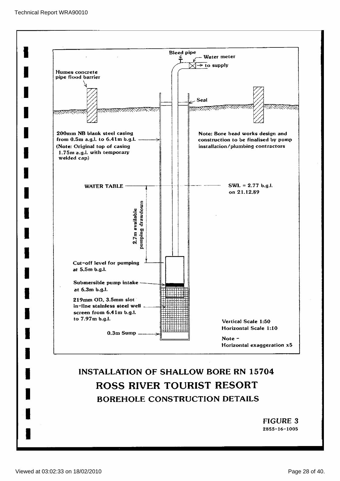
The screen is emplaced from 6.41 m to 7.97 m b.g.l. (see
Figure 3). A 0.15 m"length of casing was cut from the
top and a temporary cap welded on to prevent foreign
matter from entering the bore.
The bore was developed for nearly three hours by
air-jetting inside the screen. After one hour the depth
,>,as tagged and a 0.5 m thickness of sediment had buil t
up and was subsequently flushed out. The yield from the
airlift development was estimated visually to be more
than 10 LiS.
This bore has been designated RN 15704.
Technical Report WRA90010
Viewed at 03:02:33 on 18/02/2010 Page 12 of 40.
I I I I I I I I I I I I I I I I I I I I
6. PUMPING TEST
6.1 OPERATION AND FIELD DATA COLLECTION
A 100 minute duration, constant rate pumping test was
performed on the shallow bore, RN 15704 using a positive
displacement 'Mono' pump. The discharge Late was 8.8
Lis (measured by a 65 mm diameter orifice plate). After
one hour the drawdown stabilised at 1.88 m (that is 4.65
m b.g.l. with a SWL of 2.77 m b.g.l. before stal't of
pumping). owing to time constl'aints (the test was
performed on the last working day prior to. Christmas)
the test could not be continued longer and the recovery
of the water table was not monitored after cessation of
pumping.
Prior to the completion of the test a watel' sample was
taken fol' chemical analysis. The results of this
analysis are unavailable at the time of writing, (see
section 8 for explanation; Appendix B gives the results
of an analysis of a water sample taken from the dug
well, RN 3396).
Observation drawdown readings were taken in the dug well
40 m away from the pumped well. However, the water
table remained static in this well for the duration of
the test. Hence the radius of influence of the pumped
bore at a discharge rate of 8.8 Lis was less than 40 m.
During the test some sand and gravel particles continued
to pass through the screen. Therefore, at the end of
the test, surge pumping was performed for 50 minutes at
different depths within the screen and the sump in order
to clean the hole. However, owing to the large aperture
of the screen occasional coarse sand particles are
likely to be produced for some time to come.
Technical Report WRA90010
Viewed at 03:02:33 on 18/02/2010 Page 13 of 40.
I I I I I I I I I I I I I I I I I I I I
measurements (relative to SWL before start of pumping),
taken by means of an electrical contact gauge, at
recorded times.
6.2 ANALYSIS
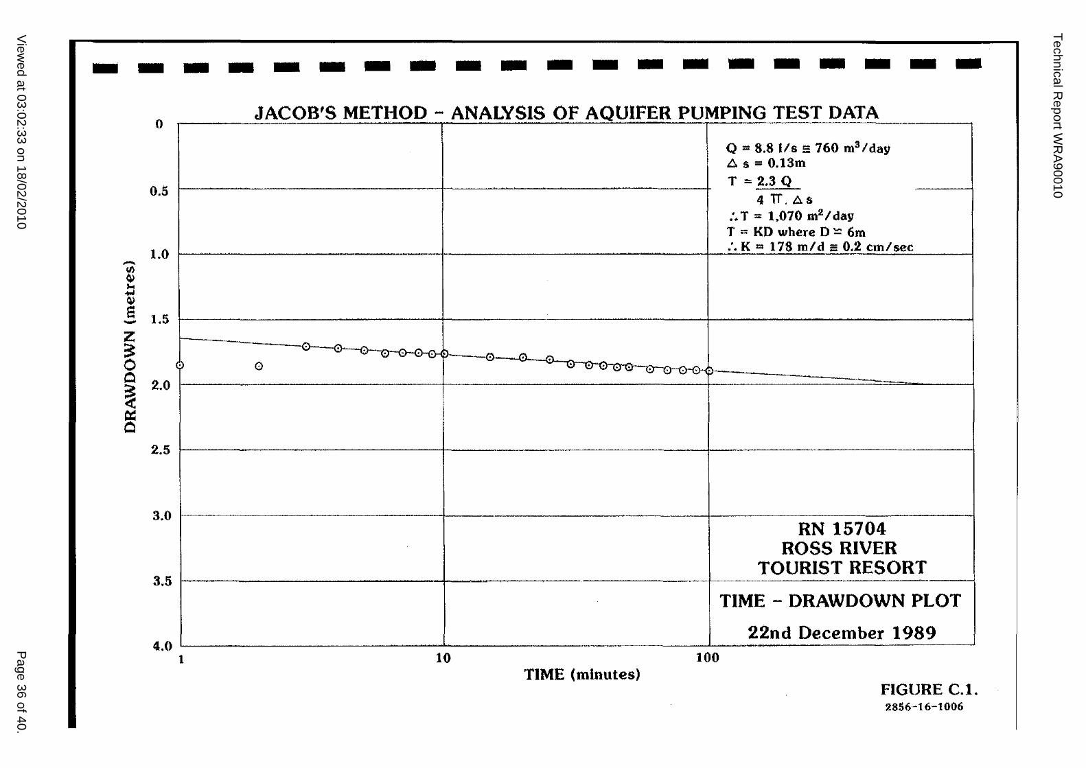
The 'Jacob straight line method' was used to analyse the
data. The analysis is given in Appendix C.l.
'l'he result of analysing the dra>ldo>ln graph gives a
transmissivity T. value as follows:
Taking a
hydraulic
saturated thickness,
conductivity, k - 178
D of
m/day.
6 m then the
This k value is indicative of a permeable gravel
aquifer. A typical value for the specific yield, S of
such an aquifer is 0.2 (Unable to calculate S owing to
the lack of observation drawdown data).
Using the maximum measured drawdown value in Bore
RN 15704 and the T and S values given above, a well
efficiency of 35%, at the test's discharge rate of 8.8
Lis, has been calculated (see Appendix C.2)
Technical Report WRA90010
Viewed at 03:02:33 on 18/02/2010 Page 14 of 40.
I I I I I I I I I I I I I I I I I I I I
6.3 EVALUATION OF THE RESULTS
An analysis of the long-term pumping yield ensues. For
the purpose of this analysis on-set of steady-state
hydraulic conditions beyond one hour's pumping duration
(where the drawdown established at 1.88 m b.g.I. for the
remainder of the test) is ignored as this may be only a
temporary manifestation of storage.
6.3.1 Maximum Production yield of Bore RN 15704
(Refer to Appendix C.3 for calculations supporting the
results given in this Section).
AS the top of the screen is set at 6.41 m b.g.l., the
base setting for the suction intake of the pump should
be approximately 6.3 m b.g.I. The shut-off level for
production will be approximately 5.5 m b.g.l. The maximum permissible drawdown equals the shut-off
level (5.5 m) minus the SWL (2.77 m) ~2.7 m.
At this drawdown the maximum production yield should be
achieved.
The maximum production yield for one year's continuous
pumping should be about 7 Lis, allowing for a well
efficiency of 35% and no aquifer recharge boundary.
However, it must be considered that
depletion of the aquifer, a reduction in
thickness (lowering of the water table)
with natural
the saturated
will decrease
the transmissivity and available drawdown at Bore
RN 15704. Therefore, in a run of dry years its maximum
production yield will be curtailed. This is discussed
further in Section 7.
Technical Report WRA90010
Viewed at 03:02:33 on 18/02/2010 Page 15 of 40.
I I I I I I I I I I I I I I I I I I I I
6.3.2 Screen Entrance Velocity
At a maximum production
entrance velocity would be
Appendix C.4) This is
yield
about
half
of 7 L/S the screen
0.015 m/sec. {refer to
the maximum allowable
entrance velocity and would ensure that the water would
not exhibi t turbulent flow. (Turbulent flow can resul t
in deleterious effects upon the soil formation close to
the bore walls, such as sand
incrustation/corrosion effects
drawdown in the well).
cavi tation, may enhance
and may produce more
Technical Report WRA90010
Viewed at 03:02:33 on 18/02/2010 Page 16 of 40.
I I I I I I I I I I I I I I I I I I I I
7. ESTIMATED SAFE YIELD OF THE BORE
7.1 PEAK DEMAND FROM BORE RN 15704
Based upon earlier estimates of the water demand (refer
to Section 1) a peak demand of 5 Lis may be anticipated
to cope with instantaneous supply where storage is
unavailable or empty. Therefore it is advised that a submersible pump of maximum capacity 5 Lis should be
installed in Bore RN 15704.
Using the Theis equations (Appendix C.2) and the pumping
test results; at a discharge rate of 5 Lis, a drawdown
of 1. 95 m after one year's pumping, at an efficiency of
35% may ensue. This would allow the SWL to deepen a
further 0.8 m below 2.77 m, through groundwater storage
depletion without affecting the pump's setting in the
bore.
7.2 AQUIFER DEPLETION AT THE SAFE YIELD
The safe yield defines the rate at which water can be
withdrawn from an aquifer perennially under specified
operating conditions without progressively depleting groundwater storage. Because the alluvial aquifer at
Ross River receives periodic recharge and has a shallow
water table it is unlikely that degradation of water
quality would occur after prolonged pumping. Neither is
it possible that uneconomic pumping conditions would
arise. Therefore we are concerned only with the reserve
of groundwater available. Because it is a very small,
unconfined basinal aquifer, storage rather than throughflow is the critical factor in deciding the safe
yield.
Technical Report WRA90010
Viewed at 03:02:33 on 18/02/2010 Page 17 of 40.
I I I I I I I I I I I I I I I I I I I I
To estimate the water available from storage a water
balance study is necessary. However, this is beyond the
scope of this report. The alluvial aquifer will be
recharged only when the Ross River periodically floods.
Therefore, a long, progressive decline in the water
table, hence decrease in storage is the norm between
infrequent floods.
At present, assuming that the alluvial aquifer has an
average width of 200 m, a length of 1500 m, a saturated
thickness of 4.5 m and a specific yield of 0.2 the
aquifer has a storage volume of 270 ML. Simplistically,
this volume could support just over I 1/2 year's pumping
at a production yield of 5 Lis with no recharge.
(Assuming that all the groundwater is recoverable).
This calculation does not account for decline in the
water table (hence decreased
decreased transmissivity).
7.3 CONCLUSION
saturated thickness and
Section 7.2 appears to indicate a sustainable yield of
5 LiS providing that the aquifer is recharged by a flood
occurring not less than once per year. Furthermore, as
calculated above, a maximum production yield of 5 LiS is
unlikely to de-water the pump.
On a daily operational basis it is suggested that the
bore is pumped at no more than 3 Lis into a storage
reservoir (100 kL capacity) that will balance peak
demands in the supply system. This production yield
will provide a margin of safety to conserve aqui fer
storage and prevent excessive drawdowns.
Nevertheless, after a prolonged severe drought period it
might prove necessary to lower the pump close to the
bottom of the bore so that its intake is within the
screen.
Technical Report WRA90010
Viewed at 03:02:33 on 18/02/2010 Page 18 of 40.
I I I I I I I I I I I I I I I I I I I I
A cut-off switch should be positioned approximately
0.8 m above the pump's intake to automatically turn off
the pump to prevent excessive drawdown de-watering and
burning out its motor.
The installation of a second shallow bore approximately
40 m away from RN 15704 is recommended. This bore will
act as a standby in case of malfunction in RN 15704.
A flow meter should be installed on the supply line to
monitor and, if necessary, adjust the production yield.
Technical Report WRA90010
Viewed at 03:02:33 on 18/02/2010 Page 19 of 40.
I I I I I I I I I I I I I I I I I I I I
8. WATER QUALITY
One pumped groundwater sample was taken from Bore
RN 15704, at the close of the pumping test using a one
litre plastic, air-tight bottle held below the discharge
end of the orifice. Owing to the Christmas holidays the
results of the analysis have not been forwarded from our
Darwin laboratory in time for inclusion in this report.
(It will be forwarded to you as an addendum).
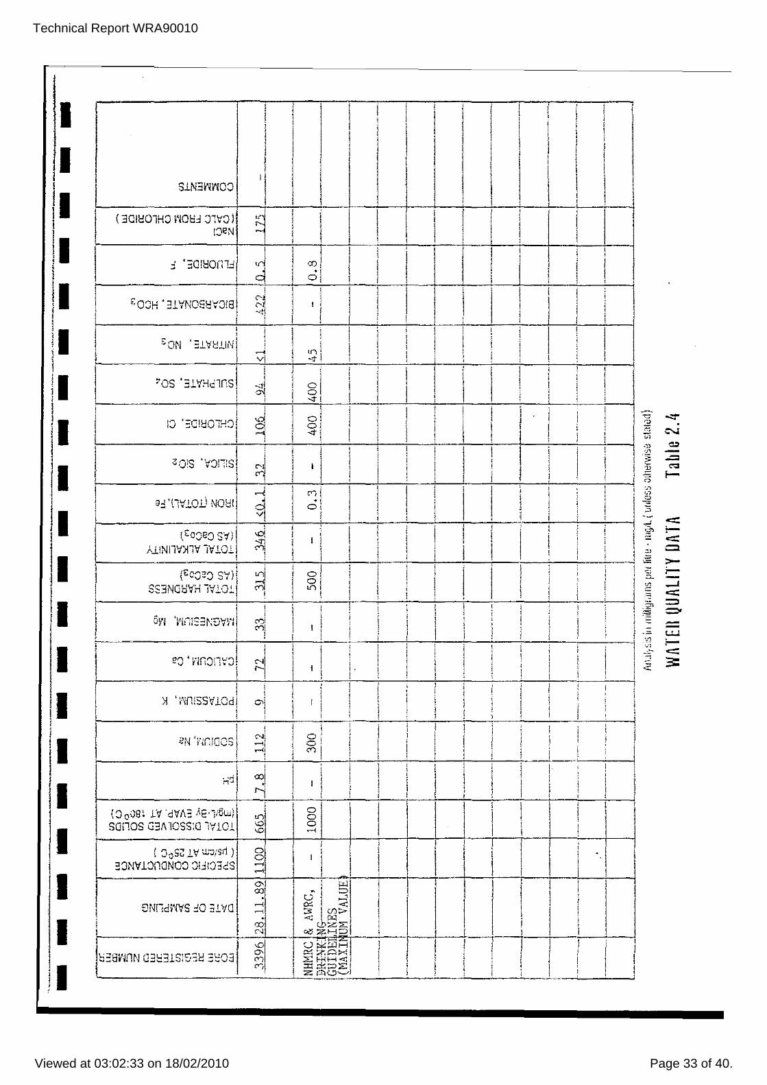
In view of the above, the results of an analysis of a
standing. water sample taken from the dug well, RN 3396
are presented in Appendix B. Because RN 3396 is close
to and in the same hydrogeological environment as
RN 15704, the sample should represent adequately the
chemical quality in the alluvial aquifer. (The sample
from RN 15704 is expected to be of better quality owing
to pumping induced throughflow).
A summary of
(NHMRC & AWRC,
the drinking water
1987) is presented
comparative purposes.
quality guidelines
in Appendix B for
The groundwater as sampled is chemically suitable for
and It is a fresh, very hard domestic purposes.
alkaline water. It is chemically classified as a
calcium bicarbonate water
cation exchange with sodium.
with a propensity for
Samples were not taken for bacteriological purposes.
However, routine disinfection of the water supply is
recommended but is beyond the scope of this report to
comment upon.
Technical Report WRA90010
Viewed at 03:02:33 on 18/02/2010 Page 20 of 40.
I I I I I I I I I I I I I I I I I I I I
Once the new bore RN 15704 has been equipped, the dug
well, RN 3396 should be sterilised by super-chlorination
and then backfilled to ground level with river sand to
neutralise it as a source of bacterial pollution.
It is suggested that the bore should be equipped with an
electro-submersible pump set inside the casing. This
installation will ensure that no surface water is
allowed to enter the bore as the borehead can be sealed.
The pump's position in the bore is displayed
schematically in Figure 3.
Technical Report WRA90010
Viewed at 03:02:33 on 18/02/2010 Page 21 of 40.
I I I I I I I I I I I I I I I I I I I I
9. CONCLUSIONS
I An attempt to complete the sink ing of a partially
installed large diameter, concrete well (designed and
abortively installed by a private contractor) failed.
The well was left abandoned in the bed of the Ross
River.
II A cross-river traverse was per-formed, using an
air-jetting tool, to investigate the nature and depth of
alluvium unde rlying the bed of the Ross River. From
this survey a suitable site was identified to install a
shallow bore, 40 m to the north-east of the abandoned
concrete well.
III A 200 mm diameter shallow bore of total depth 8.27
m b.g.I. was installed in the alluvium by means of
air-jetting.
It has been designated Bore RN 15704.
shown in Figure 3 of this report.
Its details are
IV From an analysis of a short duration aquifer
pumping test in Bore .RN 15704; a maximum continuous
production yield of 7 Lis should be achieved. (This
analysis assumes that no aquifer recharge boundaries
come into fruition and that the bore has a calculated
efficiency of 35%). However, the above quoted yield may
not be sustainable with natural recession of the water
table during droughts (depletion of aquifer storage).
Technical Report WRA90010
Viewed at 03:02:33 on 18/02/2010 Page 22 of 40.
I I I I I I I I I I I I I I I I I I I I
V Based upon the aquifer's calculated storage volume
a tentative estimate of the perennial safe yield of the
aquifer is 5 L/s. This estimate does not account for a
prolonged natural recession of the ,,,ater table as it
depends upon the aquifer being recharged by a flood
occurring in the Ross River at a recurrence interval of
not less than once per year.
VI Owing to the large aperture (3.5 mm) of the well
screen (necessary to achieve a good inflow of
groundwater), despite development by air-jetting and
pumping the bore, occasional coarse sand particles are
likely to be produced for some time. However, this condi tion is amel iorated by the screen entrance velocities achieved as a result of choosing this type of
screen.
VII Although the results of a chemical analysis made on
a pumped water sample from RN 15704 are unavailable at
the time of writing, a water sample taken from the dug
well, RN 3396 is reckoned to be representative of the
quality of the alluvial aquifer. The groundwater is
chemically sui table for domestic purposes. It is a fresh, very hard and alkaline water. Bacteriological
analysis was not carried out.
Technical Report WRA90010
Viewed at 03:02:33 on 18/02/2010 Page 23 of 40.
I I I I I I I I I I I I I I I I I I I I
10. RECOMMENDATIONS
I Although Bore RN 15704 is capable of yielding 7 Lis
given the present water table level, it is recommended
that the maximum production yield should not exceed
5 Lis.
II The bore may be equipped with a electro-submersible
pump of maximum rated production capacity 5 Lis. The
borehead should be sealed to prevent ingress of surface
water during floods.
III Notwithstanding Recommendation I, a daily pumping
rate of no more than 3 Lis is recommended. This
production yield \qill provide a margin of safety to
conserve aquifer storage and prevent excessive
drawdowns.
IV An automatic electrical cut-off switch should be
strapped to the rising main 0.8 m above the pump's
intake to prevent possible de-watering and burn-out of
the pump's motor. The occurrence and frequency of
drawdown producing pump cut-out should be monitored and
recorded ;.the production yield reduced accordingly.
V A bulk flow meter should be installed on the supply
line to monitor and adjust the production yield.
VI A storage tank (the volume to be calculated and
advised by a water supply installation contractor)
should be utilised in order to balance peak demands in
the supply system. It should also provide 24 hours'
storage for emergencies (e.g. pump breakdown).
Technical Report WRA90010
Viewed at 03:02:33 on 18/02/2010 Page 24 of 40.
I I I I I I I I I I I I I I I I I I I I
VII A second shallow bore should be installed 40 m away
from RN 15704 to act as a standby supply.
VIII Routine disinfection of the water supply is recommended. The celevant state health authority should
be consulted concerning this aspect.
IX The dug well, RN 3396 should be super-chlorinated
and backfilled.

Technical Report WRA90010
Viewed at 03:02:33 on 18/02/2010 Page 25 of 40.
I FIGURES I I I I I I I I I I I I I I I I I I I
Technical Report WRA90010
Viewed at 03:02:33 on 18/02/2010 Page 26 of 40.
I I I
INSET
I I I I I I I I I I I I I I I I I
~) (
(J
o 20 I;;;; ------ -
'"
134 11 30t
I
20 40
.. ' iJ
.NORTHERN Tl::RR1TORY
\'{ ~ . I .
Tennant Creek s ROSS RIVER ,
\ ,
\ . \ ,
L._.
~"'-+..j...:--~""";
HWY
i TOURIST RESORT .' .
ALICE SPRINGS
I . I ,
._._.J
LOCATION MAP
FIGURE 1 2854 16 1004
Technical Report WRA90010
Viewed at 03:02:33 on 18/02/2010 Page 27 of 40.
I I I I I I I I I I I I I I I I I I I I
ROSS RIVER
LEGEND o • X a
---------/---~ .. --
BORE RN 15704
ABANDONED CONCRETE WELL
INVESTIGATION HOLES
DUG WELL RN 3396
TRAVERSE UNE
TRACK
FENCE
WATERCOURSE
500m
SCALE 1: 80,000 (Approx)
ROSS RIVER TOURIST RESORT
SITE PLAN
FIGURE 2 2857-16-1007
Technical Report WRA90010
Viewed at 03:02:33 on 18/02/2010 Page 28 of 40.
I I I I I I I I I I I I I I I I I I I I
200mm NB blank steel casing from O.5m a.g.l. to 6.41m b.g.1. ---'?-iii (Note: Original top of casing 1.75m a.g.1. with temporary welded cap)
pipe r Water meter
1><1- to supply
Note: Bore head works design and construction to be finalised by pump installation/plumbing contractors
WATER TABLE ----y--1f-+ '-R----·-- .--- SWL ; 2.77 b.g.!. on 21.12.89
Cut-off level for pumping at 5.5m b.g.!.
Submersible pump intake at 6.3m b.g.!.
219mm 00. 3.5mm slotin-line stainless steel well screen from 6.41 m b.g.!. to 7.97m b.g.1.
0.3m Sump
Vertical Scale 1 :50 Horizontal Scale 1:10
Note -Horizontal exaggeration x5
INSTALLATION OF SHALLOW BORE RN 15704
ROSS RIVER TOURIST RESORT BOREHOLE CONSTRUCTION DETAILS
FIGURE 3 2855-16-1005
Technical Report WRA90010
Viewed at 03:02:33 on 18/02/2010 Page 29 of 40.
I APPENDIX I I I I I I I I I I I I I I I I I I I
Technical Report WRA90010
Viewed at 03:02:33 on 18/02/2010 Page 30 of 40.
I I I I I I I I I I I I I I I I I I I I
APPENDIX A
ALLUVIUM SAMPLING TRAVERSE ACROSS ROSS RIVER
Technical Report WRA90010
Viewed at 03:02:33 on 18/02/2010 Page 31 of 40.
I I I I I I I I I I I I I I I I I I I I
APPENDIX A
ALLUVIUM SAMPLING TRAVERSE ACROSS ROSS RIVER
(FROM CONCRETE WELL TO NORTH-EASTERN BANK)
CHAINAGE (m)
Site of
DEPTH OF
REFUSAL
(m b.g.l.)
concrete well 0
20 5.50
Site of 40 7.35
shallow bore
(RN 15704)
60 6.76
80 7.50
East Bank 100
SOIL MATERIAL STATIC WATER
LEVEL
(m b.g.l.)
Clean gravel & 2.45
cobbles
Clean gravel & 2.77
cobbles
Dirty grey 1.63
clay
Very dirty red 2.88
clay
Technical Report WRA90010
Viewed at 03:02:33 on 18/02/2010 Page 32 of 40.
I I I APPENDIX B
I B. Results of Quality Analysis on standing water Sample from
well RN 3396.
I I I I I I I I I I I I I I I I
Technical Report WRA90010
Viewed at 03:02:33 on 18/02/2010 Page 33 of 40.
Technical Report WRA90010
Viewed at 03:02:33 on 18/02/2010 Page 34 of 40.
I I I I I I I I I I I I I I I I I I I I
C.l
C.2
C.3
C.4
APPENDICES C.l TO C.4
Pumping Test Data and Jacob's Analysis of Drawdown Graph.
Calculation of Well Efficiency of Bore RN 15704.
Maximum Production Yield of Bore RN 15704.
Screen Entrance velocity calculation.
Technical Report WRA90010
Viewed at 03:02:33 on 18/02/2010 Page 35 of 40.
• • ;. I I I I
• I I
'. I I I
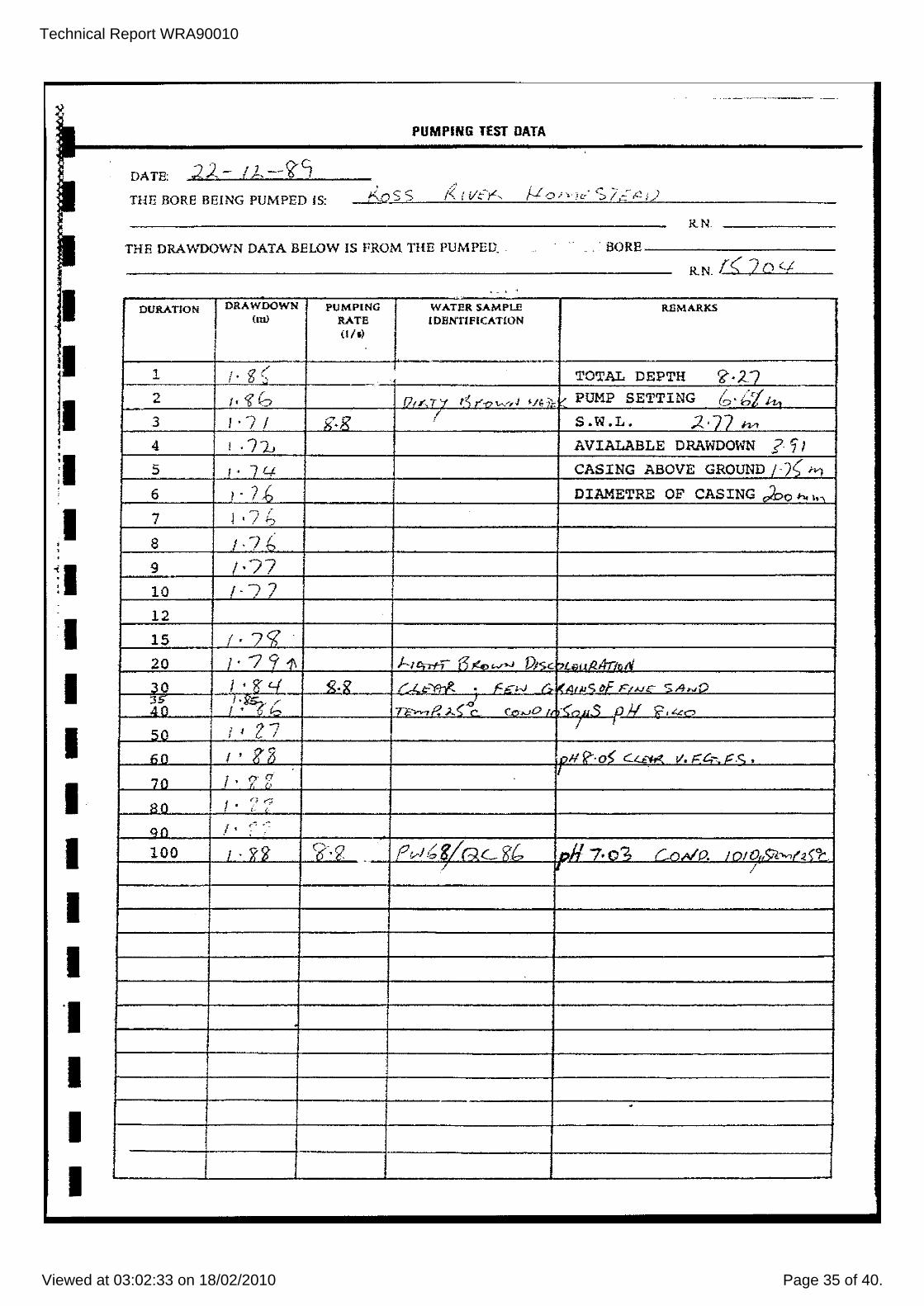
PUMPING TEST DATA
DATB:
THE BORE BEING PUMPED IS: R.N. ____ _
THE DRAWDOWN DATA BELOW IS FROM THE PUMPED .. BORE ________ __
R.N. r< 20 (j . - , -.
DURATION DRAWDOWN PUMPING WATER SAMPLE REMARKS (m) RATE IDENTIFICATION
(III)
1 /' g ( TOTAL DEPTH c;: -27 2 I' '? G 0,,".7'-( t~r." ..... r,J '/.;~ V PUMP SETTING '/1 h. b'b
3 I ''7 I x~-R I S.W.L. 2,77 Iv>
4 I ,71.J AVIALABLE DRAWDOWN ? 'i I 5 /- 74- CASING ABOVE GROUND /.)( fvJ
6 I . 7 j, DIAMETRE OF CAS ING 02:>0 ho I"
7 " r ~ , ,I 0
8 / ·7 {, 9 /-77 10 "J 7 12
15 /·7'l· 20 J·?911 /--, <>.--ri-7 ~!4, """ DI<;<: "L ' n .1-,-'" /'J
30 1''1;'-1 ~_X' r...i..t;-~ • f',n-J r ,,- "c. cF F,u"" ~ ,4,,,0
i~ " "¥"r r - . t-. TF-.-.-, P. A <1- C~>JO /, .-<~" <; () J.I "', L.c~
50 liZ 7 I
1i0 I • g;3 i,.,II!?-·oS C"""",,- V. F"'c.- C.'=. •
70 i· ?;; 80 I '
qr-; ,.
qO l . ,-'": .-: ,
100 J • x'i ~'2 . rv/,;g/RC'i;t, nil 7. o?" {_" 41'0, / ()/ O,/:;iI.>vo" ;,<"t-/ /
J
.
.
Technical R
eport WR
A90010
View
ed at 03:02:33 on 18/02/2010P
age 36 of 40.
--------------------o
0.5 1--.
1.0 .-~ ... .... Q)
e 1.5 -Z ~ 0 Q 2.0 ~ 0:: Q
2.5
3.0
3.5
4.0 1
JACOB'S METHOD - ANALYSIS OF AQUIFER PUMPING TEST DATA -
'" . '.:.. . ..A '" 0 -..:r \!T '" <:n:T <:T <:T' •
....
... - _ .. --.~-.-,-. .. .
10 100 TIME (minutes)
Q == 8.8 lIs::; 760 m3 /day As = 0.13m T = 2.3 Q I
4TT.AS :. T == 1.070 m2 /day T " KD where 0 l<: 6m :. K '" 178 mId:: 0.2 em/see .
..
RN 15704 ROSS RIVER
TOURIST RESORT
TIME - DRAWDOWN PLOT
22nd December 1989 .- ~ ...• -.--.-
FIGURE C.l. 2856-16-1006
Technical Report WRA90010
Viewed at 03:02:33 on 18/02/2010 Page 37 of 40.
I I I I I I I I I I I I I I I I I I I I
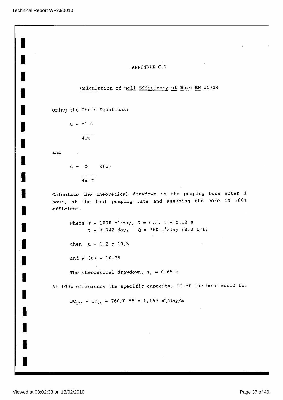
APPENDIX C.2
Calculation of well Efficiency of Bore RN 15704
using the Theis Equations:
4Tt
and
s - Q W(u)
4lt T
Calculate the theoretical drawdown in the pumping bore after 1
hour, at the test pumping rate and assuming the bore is 100%
efficient.
Where T = 1000 m'/day, S ~ 0.2, r = 0.10 m
t - 0.042 day, Q = 760 m3/day (8.8 L/s)
then u = 1.2 x 10.5
and W (u) ~ 10.75
The theoretical drawdown, St ~ 0.65 m
At 100% efficiency the specific capacity, SC of the bore would be:
SCiOO - Q/st = 760/0.65 ~ 1,169 m3/day/m
Technical Report WRA90010
Viewed at 03:02:33 on 18/02/2010 Page 38 of 40.
I I I I I I I I I I I I I I I I I I I I
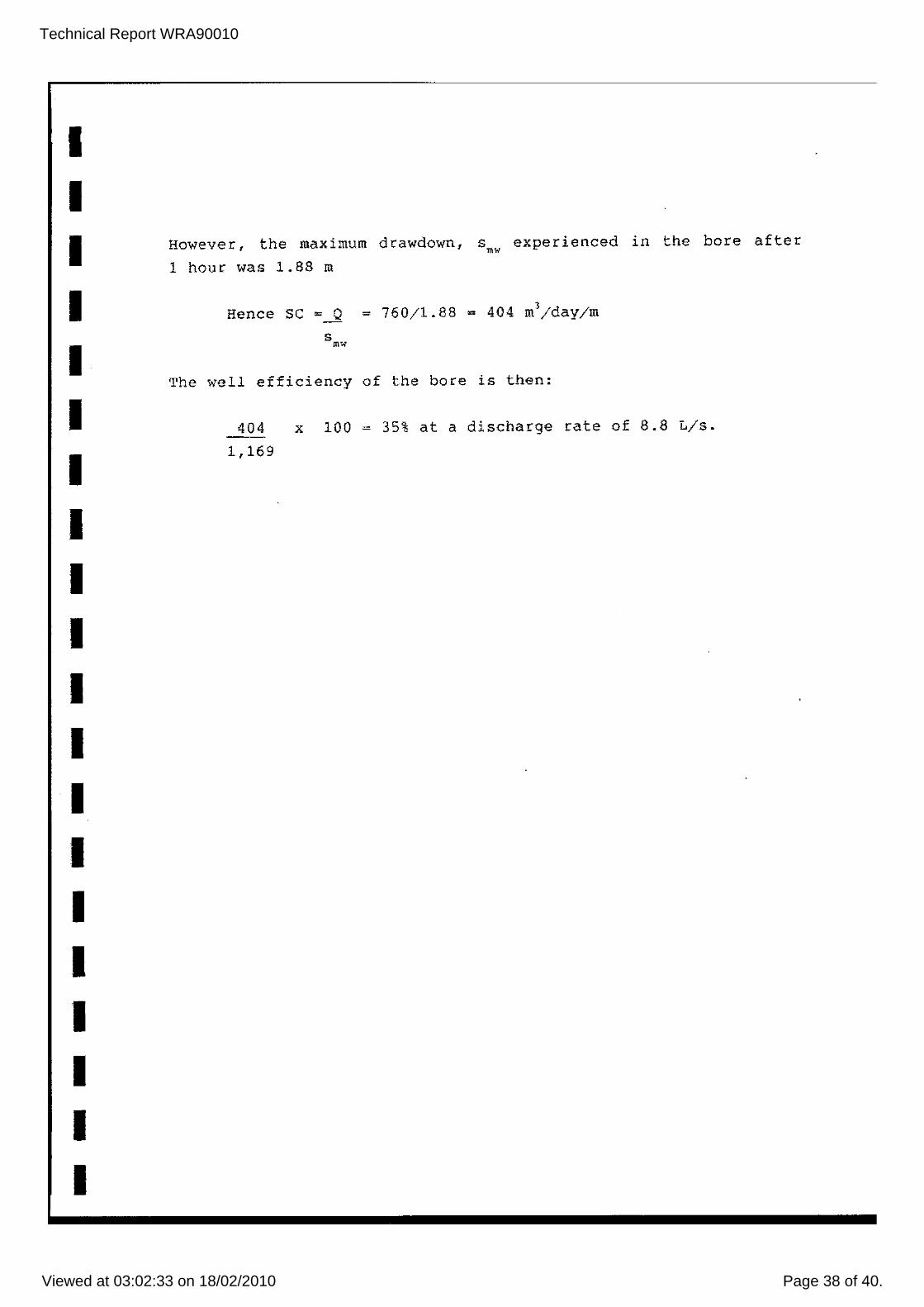
However, the maximum drawdown, smw experienced in the bore after
1 hour was 1.88 m
Hence SC ~~ = 760/1.88 = 404 m'/day/m
The well efficiency of the bore is then:
404 x 100 = 35% at a discharge rate of 8.8 Lis.
1,169
Technical Report WRA90010
Viewed at 03:02:33 on 18/02/2010 Page 39 of 40.
I I I I I I I I I I I I I I I I I I I I
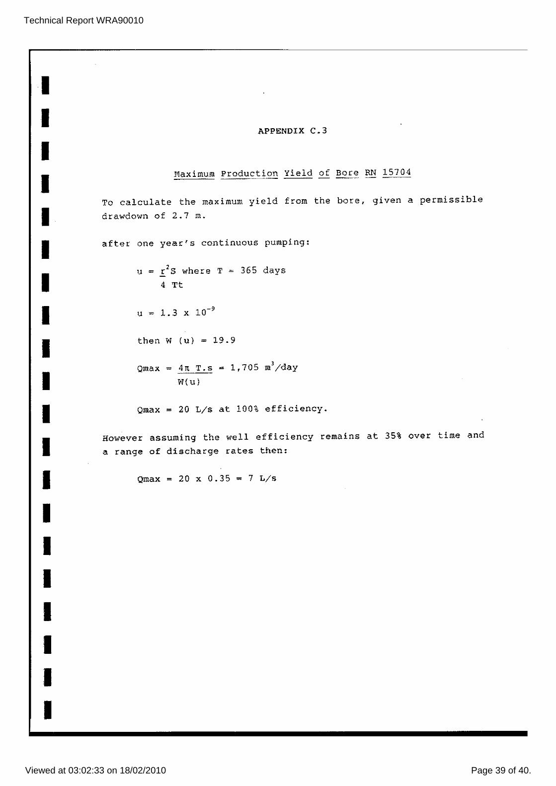
APPENDIX C.3
Maximum Production Yield of Bore RN 15704
To calculate the maximum yield from the bore, given a permissible
drawdown of 2.7 m.
after one year's continuous pumping:
, u = rOS where T = 365 days
4 Tt
u = 1. 3 X 10⁻⁹
then W (u) = 19.9
Qmax = 4n T.s = 1,705 m'/day
W(u)
Qmax = 20 Lis at 100% efficiency.
However assuming the well efficiency remains at 35% over time and
a range of discharge rates then:
Qmax = 20 x 0.35 = 7 Lis
Technical Report WRA90010
Viewed at 03:02:33 on 18/02/2010 Page 40 of 40.
I I I I I I I I I I I I I I I I I I I I
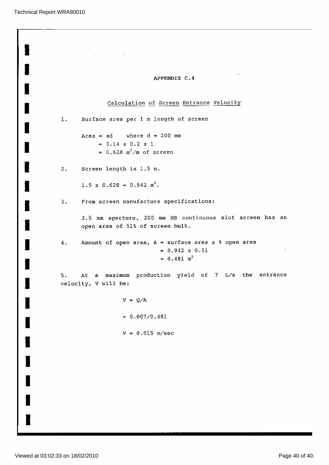
APPENDIX C.4
Calculation of Screen Entrance Velocity
1. Surface area per 1 m length of screen
Area = nd where d - 200 mm
- 3.14 x 0.2 x 1 - 0.628 m';m of screen
2. Screen length is 1.5 m.
1 0 ·' .5 x 0.628 - .942 m •
3. From screen manufacture specifications:
3.5 mm aperture, 200 mm NB continuous slot screen has an
open area of 51% of screen bulk.
4. Amount of open area, A = surface area x % open area
= 0.942 x 0.51
= 0.481 m"
5. At a maximum production yield of 7 L/s the entrance
velocity, V will be:
v = Q/A
= 0.007/0.481
V = 0.015 m/sec