installation of electrical isolation...
TRANSCRIPT

4/2013 Page 1 of 4
Installation Instructions
Isolation Sections
for Shielded Channel-Bar Electrical Conductor Bar This instruction sheet addresses the general procedure for installing Isolation Sections into TC/American Monorail Shielded Channel-Bar Electrical Conductors. Isolation Section Description
Isolation Section (part #) Length
25-1122-00 3 3/4” 25-3146-00 4 1/2” 25-3455-00 5 1/2"
Isolation Sections are short lengths of non-conductive material (phenolic) with the same cross-section as the conductor bar used in TC/American Monorail’s Shielded Channel-Bar electrification. Isolation Sections are used to create a “zone” in the conductor bar system that does not have electrical power; to create a break in the conductor bar electrical distribution system; or, for a zone in which the electrical power can be turned “on” and “off” (for example, to turn off power in the conductor bars leading to a switch, track opener or other device for which you want a positive approach barrier…sometimes referred to as “baffling”).
For zones in which there is no electrical power, the sections of conductor bar in the zone are simply left out of (not connected to) the building power distribution grid.
To create two (or more) individually powered zones in the conductor bar, the isolation sections are simply used as “dividers” between the zones.
! WARNING Open the mainline disconnect switch on systems before working on electrical equipment.
Electrical Equipment Installation, Service and Maintenance Persons performing installation, service or maintenance activities on, near, or with equipment that is electrically powered are exposed to electrical hazards that could result in serious injury or death if proper precautions are not followed. Before performing such work, disconnect the electrical power source for the system at the disconnect device and lock it out, following appropriate Lockout/Tagout (LOTO) procedures, to prevent electric power from being applied while work is being performed.
All persons must use safe work practices appropriate to the electrical system, and follow all workplace procedures and policies. This requires specific knowledge, equipment and training beyond the scope of this document. Workplace supervisors are responsible to assure that all persons under their supervision are properly trained, properly equipped, and are following appropriate safety practices.
DANGER
Installation Instructions
TC/American Monorail
Installation: Isolation Sections 4/2013 Page 2 of 4
For zones in which electrical power is to be turned either “on” or “off” upon the discretion of an operator, the sections of conductor bars in the zone must be separately connected to the general monorail power supply (building power grid) and controlled through an electrical control panel with appropriately rated switching mechanisms. See Figure 6 for a typical system using isolation sections for this purpose. See the Installation Instructions for Shielded Channel-Bar electrical conductors for making power feed connections to the bar.
Creating the Isolation Section Zones
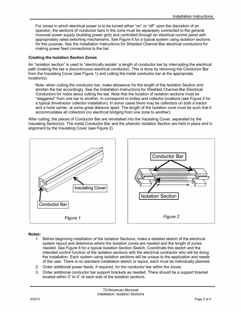
An “isolation section” is used to “electrically isolate” a length of conductor bar by interrupting the electrical path (making the bar a discontinuous electrical conductor). This is done by removing the Conductor Bar from the Insulating Cover (see Figure 1) and cutting the metal conductor bar at the appropriate location(s).
Note: when cutting the conductor bar, make allowance for the length of the Isolation Section and shorten the bar accordingly. See the Installation Instructions for Shielded Channel-Bar Electrical Conductors for notes about cutting the bar. Note that the location of isolation sections must be “staggered” from one bar to another, to correspond to trolley and collector locations (see Figure 5 for a typical drivetractor collector installation). In some cases there may be collectors on both a tractor and a hoist carrier, at some great distance apart. The length of the isolation zone must be such that it accommodates all collectors (no electrical bridging from one zone to another).
After cutting, the pieces of Conductor Bar are reinstalled into the Insulating Cover, separated by the Insulating Section(s). The metal Conductor Bar and the phenolic Isolation Section are held in place and in alignment by the Insulating Cover (see Figure 2).
Notes:
1. Before beginning installation of the Isolation Sections, make a detailed sketch of the electrical system layout and determine where the isolation zones are needed and the length of zones needed. See Figure 6 for a typical Isolation Section Sketch. Coordinate this sketch and the intended control function of the isolation sections with the electrical contractor who will be doing the installation. Each system using isolation sections will be unique to the application and needs of the user. There is no standard installation sketch or layout, each must be individually planned.
2. Order additional power feeds, if required, for the conductor bar within the zones.
3. Order additional conductor bar support brackets as needed. There should be a support bracket located within 3” to 4” of each side of the isolation sections.
Figure 1
Figure 2

Installation Instructions
TC/American Monorail
Installation: Isolation Sections 4/2013 Page 3 of 4
4. The shape of the Isolation Section allows it to fit into the Insulating Cover and provide a common path for the Collector Shoe to follow the conductor bar without interruption. Verify that the transition from conductor bar to isolation section is smooth and free of burrs.
5. Drivetractors, Hoist Carriers, Cranes or other powered equipment with electrical collectors on a zoned conductor bar system will lose electrical power as the collector shoe(s) passes across the isolation section. This will interrupt power to equipment controls, and may cause variable frequency drives to fault out (may require controls to be cycled on/off to reset and clear the fault).
6. The standard TC/American Monorail collector shoe length is shown in Figure 3. Provide an isolation Section length to match (or use a combination of Isolation Sections and conductor bar) to prevent “bridging” the collector shoe from one conductor bar segment across the isolation section to the adjacent conductor bar segment. Note: if Tandem Head Collectors are used (see Figure 4), the length of the isolation segment in the conductor bar must be adjusted accordingly (also see TC/A catalog, Electrification Section).
7. The actual installed location of Isolation Sections will depend upon the length of the carrier, the location of collectors on the carrier, and the distance the carrier requires to come to a stop (depends upon type of drive reducer, with or without brakes, travel speed, etc.). All collectors must cross onto the isolation sections at the same time.
8. Do not install isolation sections in the ground bar.
9. Carefully check the phasing of the conductor bars after installation is finished to assure that phasing is consistent throughout the entire system, including within switches and other equipment in the system.
Figure 3
Figure 4
Figure 5

Installation Instructions
TC/American Monorail
Installation: Isolation Sections 4/2013 Page 4 of 4
Typical Isolation Sketch Layout Shown in Figure 6 is a typical Isolation Section Sketch.
This is for a monorail system with switches and curves, with isolation sections on either side of the switch. Limit switches on the monorail switch, connected through the switch controls, turn power on and off to the conductor bars. This system of isolation sections and powered bars provides a “baffle” to prevent a carrier from approaching the switch when the moveable section of the switch is not in the correct position.
In this application, the isolation sections served as a “break” in the conductor bars.
Note: limit switches on the monorail switches are not standard. Contact your sales representative for pricing.
TC/American Monorail Systems, Inc. 12070 43rd St. NE
St. Michael, MN 55376 763-497-7000
Figure 6