installation of allfa europe premium...
TRANSCRIPT
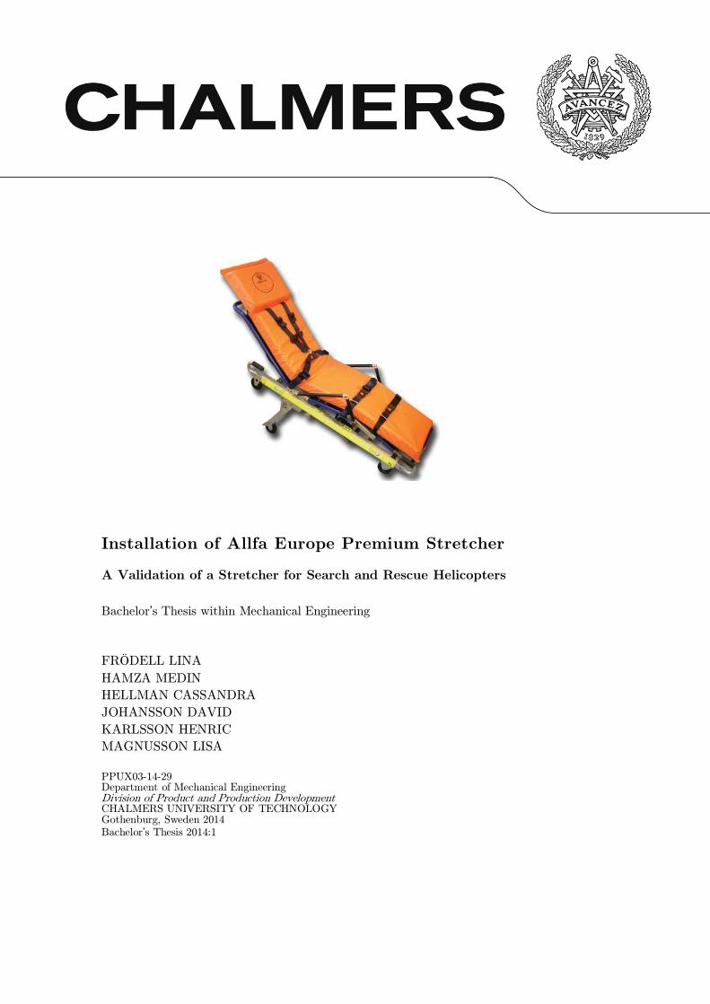
Installation of Allfa Europe Premium Stretcher
A Validation of a Stretcher for Search and Rescue Helicopters
Bachelor’s Thesis within Mechanical Engineering
FRÖDELL LINA
HAMZA MEDIN
HELLMAN CASSANDRA
JOHANSSON DAVID
KARLSSON HENRIC
MAGNUSSON LISA
PPUX03-14-29 Department of Mechanical Engineering Division of Product and Production Development CHALMERS UNIVERSITY OF TECHNOLOGY Gothenburg, Sweden 2014
Bachelor’s Thesis 2014:1

Installation of Allfa Europe Premium stretcher
A validation of a stretcher for search and rescue helicopters
Bachelor’s Thesis within Mechanical Engineering
FRÖDELL LINA
HAMZA MEDIN
HELLMAN CASSANDRA
JOHANSSON DAVID
KARLSSON HENRIC
MAGNUSSON LISA
© LINA FRÖDELL, MEDIN HAMZA, CASSANDRA HELLMAN, DAVID JOHANSSON,
HENRIC KARLSSON & LISA MAGNUSSON, 2014
Kandidatarbete/Institutionen för produkt- och produktionsutveckling,
Chalmers tekniska högskola 2014:1
Department of Mechanical Engineering
Division of Product and Production Development
Chalmers University of Technology
SE-412 96 Göteborg
Sweden
Telephone: + 46 (0)31-772 1000
Cover:
Allfa Europe Premium stretcher
(http://www.fernonorden.se/ferno/frontend/mediabank/676/allfa-eu-2008-med-ny-armst-d-
jpg-cmyk_ml.jpg)


Preface
This bachelor’s thesis was initialised by the company Heli-One and carried out during the
period January to May in 2014 at the division of Product and Production Development at
Chalmers University of Technology.
We would like to thank Heli-One for giving us this opportunity to work with an actual
project and at the same time improves our engineering competences. We are all very
grateful for the welcoming in Stavanger and for the introduction of the project. We would
specially like to thank Anders Pettersson and Cato Strandskog at Heli-One for their
guidance and help throughout the project, it have been truly appreciated.
Our supervisor, Sara Caprioli, has been a big support for us and helped throughout the
project and we thank her for her interest and dedication. We would also like to thank our
examiner, Kristina Wärmefjord, for the guidance.
We appreciate the welcoming and participating from the manufacture Ferno Norden and
for lending us the stretcher. We are also grateful to the ambulance staff in Sisjön and the
helicopter ambulance staff in Säve for answering all our questions and demonstrate how
they work with the stretcher. We would also like to thank a search and rescue contact for
answering to our questions.
Finally, we would like to thank everyone who helped us during this project.
Gothenburg May 2014
Lina Frödell, Medin Hamza, Cassandra Hellman,
David Johansson, Henric Karlsson & Lisa Magnusson

Abstract
The aim of this project was to determine whether the stretcher Allfa Europe Premium
would be able to meet the requirements in accordance to the regulations of European
Aviation Safety Agency for installation in a search and rescue helicopter. To fulfil the
regulations four different tasks had to be done; make a 3D-model of the stretcher,
validation for certification, strength analysis and development of a concept for a fixation
system. The 3D-model was created by using reverse engineering through disassembly and
analysis of the stretcher. The computational model employed for strength analysis of the
stretcher features only the load bearing part. To validate the trustworthiness of the
numerical simulation handbook calculations based on linear elastic beam theory were
performed. The results from the numerical simulation and handbook calculations show that
the stretcher withstands the loads according to the regulations. Apart from the
requirements on the loads, there are other requirements that the stretcher must fulfil. The
paragraphs stating those requirements were investigated and formulated and are a basis for
the certification. This combined with further analysis indicates that the stretcher would be
able to fulfil certification requirements in the future. As a final task a fixation system for
installation of the stretcher in a helicopter was developed.

Sammandrag
Projektets syfte var att undersöka huruvida båren Allfa Europe Premium uppfyller de krav
som ställs av European Aviation Safety Agency för att kunna installera den i en search and
rescue-helikopter samt att skapa en fullt dynamisk 3D-modell. Projektet omfattade fyra
olika deluppgifter där samtliga genomfördes med hänsyn till regelverket. Uppgifterna var
följande: Ta fram en 3D-modell av båren, genomföra en validering inför certifiering, utföra
en hållfasthetsanalys samt utveckla ett koncept för en infästningsanordning. 3D-modellen
togs fram med hjälp av reverse engineering genom att demontera och analysera en befintlig
bår. Den lastbärande delen av 3D-modellen importerades till ett simuleringsprogram där en
kontroll utfördes för att undersöka om strukturen klarar av de laster som krävs.
Beräkningarna som utfördes i simuleringsprogrammet validerades med handberäkningar för
att styrka trovärdigheten. Resultatet av beräkningarna visar att båren klarar av de
påfrestningarna som anges i regelverket. Förutom reglerna om lastfallen tar regelverket upp
flera andra paragrafer som båren måste klara av. Dessa undersöktes och lade grunden för en
validering som senare kan utvecklas för att göra en certifiering av båren. Resultatet av
valideringen indikerar att båren kommer klara en framtida certifiering. Vid sidan av detta
togs ett förslag fram på ett infästningssystem för att kunna fästa båren i helikoptern.

Notations
This is a list of all the abbreviations and letters used in the thesis.
Abbreviations
ANSYS Engineering simulation software
CAD Computer-aided design
CES Cambridge Engineering Selector
CS Certification Specification
EASA European Aviation Security Agency
Eurocode 9 DD ENV 1999-1-1:2000
FAA Federal Aviation Agency
FEM Finite element method
ISO International Organization for Standardization
LCA Life Cycle Assessment
MMPDS Metallic Materials Properties Development and Standardization
RE Reverse Engineering
SAR Search and Rescue
Roman upper case letters
[mm2] Gross area of the cross section
[MPa] Young’s modulus
[mm4] Moment of inertia
[-] Effective length factor
[mm] Length of beam
[mm] Critical length
[Nmm] Moment in general
[N] Elastic critical load; axial force
[N] Design value of the compressive force
[mm3] Section modulus
Roman lower case letters
[mm] Width
[mm] Height
[mm] Eccentricity in Y direction
[mm] Eccentricity in Z direction
[MPa] Characteristic strength for bending and overall yielding in tension and
compression
[MPa] 0.2% proof strength
[MPa] Characteristic strength for the local capacity of a net section in tension or
compression

[MPa] Ultimate tensile strength
[mm/s2]Gravitational acceleration 9810
[mm] Cross-sectional height
[mm] Radius of gyration
[mm] Cross section radius of gyration
[mm] Thickness of cross section
Greek upper case letters
[-] Reduction factor
Greek lower case letters
[-] Shape factor; Imperfection factor
[-] Slenderness parameter
[-] Buckling factor
[-] Partial safety factor
[mm] Deflection
[-] √ ⁄
[-] Efficiency
[-] Fitting factor
[-] Slenderness ratio
[-] Limit of the horizontal plateau
ʋ [-] Poisson’s ratio
[-] Factor of the distance to the deflection point
[kg/mm3] Density
[MPa] Stress
[-] Rotation; Slope; Ratio
[-] Beam columns without localized weld factor

Table of Contents
1 Introduction ............................................................................... 17
1.1 Background ......................................................................................... 17
1.2 Aim...................................................................................................... 17
1.3 Assignment .......................................................................................... 18
1.4 Limitations .......................................................................................... 18
1.5 Disposition........................................................................................... 18
1.6 Method ................................................................................................ 19
3D-modelling ............................................................................. 19 1.6.1
Validation for EASA ................................................................. 19 1.6.2
Strength Analysis ...................................................................... 19 1.6.3
Fixation System ........................................................................ 19 1.6.4
2 3D – Modelling ........................................................................... 20
2.1 Method ................................................................................................ 20
2.2 Tolerances ........................................................................................... 20
2.3 Functions............................................................................................. 21
2.4 Drawings ............................................................................................. 21
2.5 Results ................................................................................................. 21
2.6 Discussion ............................................................................................ 22
3 Validation ................................................................................... 23
3.1 Method ................................................................................................ 23
3.2 Paragraph Study ................................................................................. 23
3.3 Results ................................................................................................. 23
3.4 Discussion ............................................................................................ 26
CS 29 Subpart C - Strength Requirements ............................... 26 3.4.1
CS 29 Subpart D – Design and Construction ........................... 27 3.4.2
3.5 Conclusion ........................................................................................... 29
4 Strength Analysis ....................................................................... 30
4.1 Theory ................................................................................................. 32
4.2 Method ................................................................................................ 32
Mass of the Stretcher ................................................................ 33 4.2.1
Cross Section for Handbook Calculations ................................. 33 4.2.2
4.3 Deflection, Normal Stress and Buckling According to Linear Beam Theory 35
Deflection and Normal Stress of Main Beam due to Load Case 136 4.3.1
Deflection and Normal Stress of Joist due to Load Case 1....... 38 4.3.2
Deflection and Normal Stress of Main Beam due to Load Case 239 4.3.3
One Point Load due to Load Case 5 ......................................... 40 4.3.4
Buckling .................................................................................... 42 4.3.5
4.4 Buckling According to Eurocode 9 ..................................................... 45
4.5 Numerical Simulation .......................................................................... 45
3D-Model ................................................................................... 45 4.5.1
Loads and Boundary Conditions ............................................... 46 4.5.2
Element Definition .................................................................... 47 4.5.3
Mesh Convergence Study .......................................................... 47 4.5.4
Choice of Materials ................................................................... 54 4.5.5
Interpreting the Results ............................................................ 54 4.5.6
4.6 Results ................................................................................................. 54
Deflection, Normal Stress and Buckling According to Linear Beam Theory4.6.1
54
Eurocode 9 ................................................................................. 57 4.6.2
Numerical Simulation ................................................................ 57 4.6.3
4.7 Discussion ............................................................................................ 65
Handbook Calculations ............................................................. 66 4.7.1
Numerical Simulation ................................................................ 67 4.7.2
4.8 Conclusion ........................................................................................... 70
4.9 Optimisation ....................................................................................... 70
5 Fixation System .......................................................................... 78
5.1 Method ................................................................................................ 78
Attachments .............................................................................. 79 5.1.1
5.2 Black Box and Function Structure ..................................................... 79
5.3 Requirement Specification................................................................... 81
5.4 Brainstorming ..................................................................................... 82
Concept A – Ambulance Fixation ............................................ 82 5.4.1
Concept B – The Pinball .......................................................... 82 5.4.2
Concept C – The Sideway ........................................................ 82 5.4.3
Concept D – The Pit ................................................................ 83 5.4.4
Concept E – The Taxi .............................................................. 83 5.4.5
Concept F – The Claw .............................................................. 83 5.4.6
Concept G – Helicopter Fixation .............................................. 84 5.4.7
Concept 1 – The Lift................................................................. 84 5.4.8
Concept 2 – The Slide ............................................................... 85 5.4.9
Concept 3 – The Rail ................................................................ 85 5.4.10
Concept 4 – The Rotation ........................................................ 85 5.4.11
5.5 Matrices ............................................................................................... 86
5.6 Results ................................................................................................. 87
Fixation Point 1 ........................................................................ 87 5.6.1
Fixation Point 2 ........................................................................ 88 5.6.2
Steering Device .......................................................................... 89 5.6.3
Materials and Manufacturing .................................................... 90 5.6.4
Achieved Requirement Specification. ........................................ 91 5.6.5
5.7 Discussion ............................................................................................ 92
5.8 Further Development .......................................................................... 92
6 Discussion ................................................................................... 94
6.1 Reflection of Method ........................................................................... 95
7 Conclusion .................................................................................. 96
8 Recommendations ....................................................................... 97

17
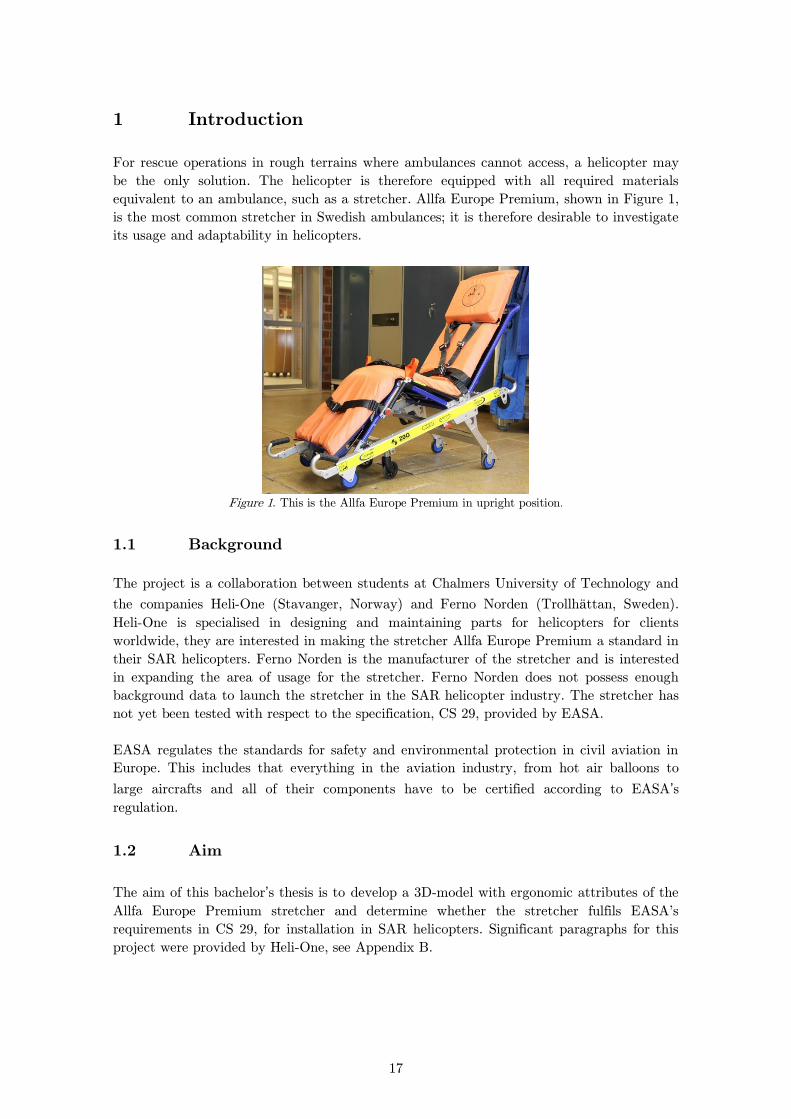
1 Introduction
For rescue operations in rough terrains where ambulances cannot access, a helicopter may
be the only solution. The helicopter is therefore equipped with all required materials
equivalent to an ambulance, such as a stretcher. Allfa Europe Premium, shown in Figure 1,
is the most common stretcher in Swedish ambulances; it is therefore desirable to investigate
its usage and adaptability in helicopters.
Figure 1. This is the Allfa Europe Premium in upright position.
1.1 Background
The project is a collaboration between students at Chalmers University of Technology and
the companies Heli-One (Stavanger, Norway) and Ferno Norden (Trollhättan, Sweden).
Heli-One is specialised in designing and maintaining parts for helicopters for clients
worldwide, they are interested in making the stretcher Allfa Europe Premium a standard in
their SAR helicopters. Ferno Norden is the manufacturer of the stretcher and is interested
in expanding the area of usage for the stretcher. Ferno Norden does not possess enough
background data to launch the stretcher in the SAR helicopter industry. The stretcher has
not yet been tested with respect to the specification, CS 29, provided by EASA.
EASA regulates the standards for safety and environmental protection in civil aviation in
Europe. This includes that everything in the aviation industry, from hot air balloons to
large aircrafts and all of their components have to be certified according to EASA’s
regulation.
1.2 Aim
The aim of this bachelor’s thesis is to develop a 3D-model with ergonomic attributes of the
Allfa Europe Premium stretcher and determine whether the stretcher fulfils EASA's
requirements in CS 29, for installation in SAR helicopters. Significant paragraphs for this
project were provided by Heli-One, see Appendix B.

18
1.3 Assignment
In order to analyse the stretcher’s suitability, the following tasks are covered:
Development of a 3D-model of the stretcher with all its dynamic functions.
Validation for certification of the stretcher according to EASA regulations.
Strength analysis of the stretcher with respect to given ultimate static loads using
finite element method. The analysis includes handbook calculations based on
linear beam theory and numerical simulations.
Identify and analyse different fixation systems and develop a final fixation system
concept for the stretcher.
1.4 Limitations
The strength analysis does not take fatigue and wear issues or vibrational and dynamic
loads into account. The model used for the numerical simulations features the load bearing
part of the stretcher, see Figure 2.
Figure 2. The load bearing part
The development of the fixation system does not take the fixation between the system and
the helicopter into account. By not taking a certain helicopter interface into account one
expands the opportunity of system installation into several helicopter types.
1.5 Disposition
The project is divided into four sections, it has been appropriate to divide the report after
these sections to make it as easy to read as possible. Every section has the same structure
with its own introduction/theory, method, result and discussion. Finally, the report
includes a discussion, conclusion and recommendation for the whole project.
The four sections are:
Chapter 2 - 3D-Modelling
Chapter 3 - Validation for Certification
Chapter 4 - Strength Analysis
Chapter 5 - Fixation System
19
1.6 Method
How to work with 3D-modelling is very different from how to perform a strength analysis
therefore follows a short introduction of the methods below. A more detailed method is
presented in each chapter.
3D-modelling 1.6.1
The 3D-model is developed through reverse engineering; a real full-scale stretcher provided
by Ferno Norden was used as background material for sizes, shapes and functions of the
stretcher to be represented in the model. The CAD software used for this was Autodesk
Inventor 2014.
Validation for EASA 1.6.2
The validation of the stretcher is achieved by detailed studies of the EASA regulations
chapter CS-29, Large Rotorcrafts, book 1 and book 2. Book 1 describes the paragraphs and
book 2 describes how the paragraphs should be interpreted. FAA, which is the
corresponding American version of EASA, is used as a complement.
Strength Analysis 1.6.3
According to EASA the stretcher has to withstand loads in several directions and in
different conditions due to the different scenarios that the helicopter can be subjected to in
case of crash landing or safety landing. The strength analysis includes handbook
calculations as well as numerical simulations, following directives from Heli-One. Linear
buckling analysis with respect to critical loads is also performed. The method for the
calculations follows design practices according to linear beam theory and Eurocode 91. The
software used for the numerical stress-analysis was Autodesk Mechanical Simulations 2014.
Fixation System 1.6.4
In order to fulfil the EASA requirements in CS 29, the stretcher needs to be fastened inside
the helicopter in order to not cause any injuries on occupants or damage to the surrounding
structure. The fixation system is developed both by conventional engineering and reverse
engineering, which includes both searching for existing products on the market and through
generating new ideas. Conventional engineering and Reverse engineering were obvious
chosen methods for this part of the project because they are commonly known for product
development.
1 British Standards Institution, Eurocode 9, DD ENV 1999-1-1:2000
20
2 3D – Modelling
The manufacturing company, Ferno Norden needs a 3D-model of the stretcher for
demonstration to their customers. They also lack models of the individually components,
which can be necessary when searching for spare parts and for maintenance. Heli-One
develops the interior for the SAR helicopter and is therefore interested in implementing the
3D-model of stretcher in the SAR interior. This chapter describes the process of developing
the 3D-model.
2.1 Method
A full-sized stretcher, lend by Ferno Norden was used as the base for creating the 3D-
model. All different parts of the stretcher were constructed in the 3D-modelling program
Autodesk Inventor 2014 and then assembled to form a complete model.
The stretcher was disassembled to identify all the individual parts. As the stretcher consists
of over 150 unique parts it required a system to keep track of all these. All of the individual
parts obtained its own article number. The Bill of Material, BOM, illustrates a list of these
parts. The list was created with the software BOM Tools Pro. Drawings of every single
component except from screws, nuts and plates were made as a complement.
Each part was separately created in the 3D-model program and later assembled. Constrains
were added to assemble the stretcher and make it fully dynamic. Information about
materials for the critical components was provided by the manufacturer. For parts where no
material information was provided, assumptions were made based on material properties.
Measurements of the components were made by a calliper, which resulted in relatively large
tolerance for the dimensions. This will be discussed in chapter 2.2. Working with this type
of method is called reverse engineering and the philosophy behind this is described as
below:
“In the fields of mechanical engineering and industrial manufacturing the term Reverse
Engineering refers to the process of creating engineering design data from existing parts
and/or assemblies. While conventional engineering transforms engineering concepts and
models into real parts, in the reverse engineering approach real parts are transformed into
engineering models and concepts.”2
2.2 Tolerances
Tolerances are essential to the design data because it immediately affect the manufacturing
of the part. The reverse engineering design will in most cases differ from the original part
that was examined in the beginning, therefore the importance of tolerances. High
geometrical and dimensional precision directly indicates higher quality to the product but
2 Kaisarlis, George J. A Systematic Approach for Geometrical and Dimensional Tolerancing in Reverse
Engineering, 2012
21
increases the cost.3
Two different types of tolerances had to be considered; manufacturing tolerance and
measurement tolerance. ISO standard tolerances were not considered due to inaccessibility.
When a vernier calliper and a steel rule were used, an accuracy of 1mm was achieved on
non-critical dimensions. The critical dimensions, such as the cross sections on the beams,
were measured with a dial calliper with an accuracy of 0.5mm.
The stretcher may contain components with a wider manufacturing tolerance than
measurement tolerance. According to the manufacturer almost every manufacturing
tolerance are narrower than the measurement tolerances, 1mm for non-critical components
and 0.5mm for critical components.
2.3 Functions
The stretcher is versatile and has many different functions that facilitate for the paramedics
and also make it more comfortable for the patient. Ergonomic attributes were included in
the 3D-model and are described below. Pictures of the parts and functions are presented in
Appendix A and Appendix H.
Both the backrest and footrest are height adjustable so that the patient can sit
and lay in different positions.
Flywheels and assistant wheels are installed to make it easier to move and run
the stretcher on rough ground.
Adjustable handles both in front and back of the stretcher. They can be
adjusted for every paramedic that is carrying the stretcher and thereby
facilitate their work.
A yoke is installed so that the paramedics easier can lift the stretcher when
walking in staircases.
Side handles used when the stretcher needs to be lifted by several people.
Armrests for the patient.
2.4 Drawings
Drawings of all parts except nuts, screws and plates were made. They were extracted from
the 3D-models according to ISO standard with guidelines from Heli-One. The dimensions of
the drawings were made with baseline dimension.
2.5 Results
This part of the project resulted in a 3D-model including all of the functions described in
3 Kaisarlis, George J. A Systematic Approach for Geometrical and Dimensional Tolerancing in Reverse
Engineering, 2012
22
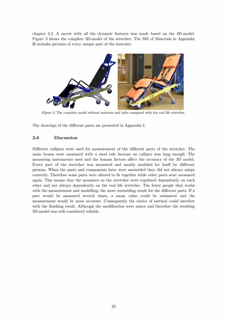
chapter 2.3. A movie with all the dynamic features was made based on the 3D-model.
Figure 3 shows the complete 3D-model of the stretcher. The Bill of Materials in Appendix
H includes pictures of every unique part of the stretcher.
Figure 3. The complete model without mattress and belts compared with the real life stretcher.
The drawings of the different parts are presented in Appendix I.
2.6 Discussion
Different callipers were used for measurement of the different parts of the stretcher. The
main beams were measured with a steel rule because no calliper was long enough. The
measuring instruments used and the human factors affect the accuracy of the 3D model.
Every part of the stretcher was measured and mostly modeled for itself by different
persons. When the parts and components later were assembled they did not always adapt
correctly. Therefore some parts were altered to fit together while other parts were measured
again. This means that the measures on the stretcher were regulated dependently on each
other and not always dependently on the real life stretcher. The fewer people that works
with the measurement and modelling; the more resembling result for the different parts. If a
part would be measured several times, a mean value could be estimated and the
measurement would be more accurate. Consequently the choice of method could interfere
with the finishing result. Although the modification were minor and therefore the resulting
3D-model was still considered reliable.
23
3 Validation
The stretcher has to be certified according to the certification specification, CS, chapter 29
in EASA, in order to be installed in a helicopter. The certification has to be executed by
the agency or by an authorized company such as Heli-One. This chapter provides a
preliminary validation that could be used in a certification process.
3.1 Method
The paragraphs relevant for the stretcher are described in Appendix B. The selected
paragraphs were carefully studied and construed using AC 29, Advisory Circular from FAA
that describes how to interpret the paragraphs in CS 29. In order to ensure that all
paragraphs were reviewed, a table was made where each paragraph can be ticked off if the
requirement was met. The same requirements were fulfilled by different paragraphs in
certain cases and were therefore referred to each other. The conclusions and
recommendations can be used by the authorized company later in the certification process.
Recommendations are implemented for cases when the stretcher does not qualify or need
additional tests to ensure its suitability in the helicopter. The performed controls were to
examine the material properties both analytically and with calculations to determine
whether it is within the range of the requirements. Therefore it was necessary to use data
from strength analysis, which is presented in chapter 4.
3.2 Paragraph Study
The paragraphs in EASA, CS 29, could sometimes be ambiguous and to determine how the
paragraphs should be interpreted they were discussed in order to come to conclusions. Even
regularly contact with Heli-One was held to make sure that the paragraphs was correctly
interpreted. Daily discussions were held to make sure all calculations were performed
properly and right forces were used according to the paragraphs.
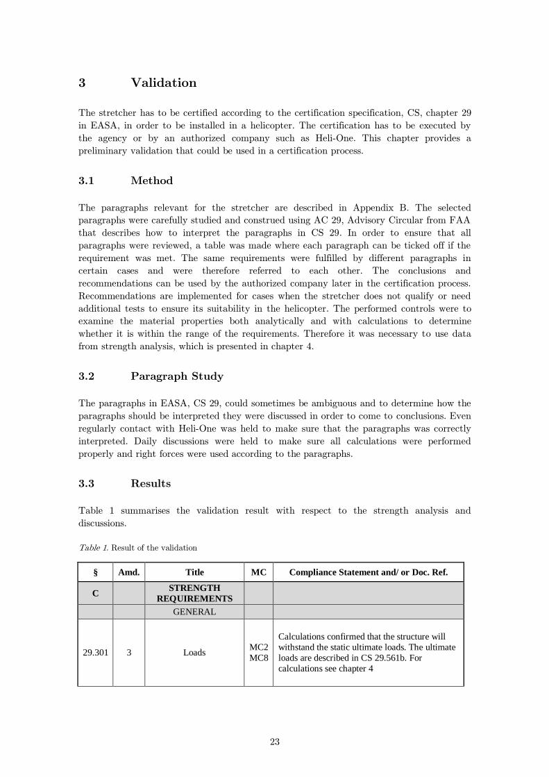
3.3 Results
Table 1 summarises the validation result with respect to the strength analysis and
discussions.
Table 1. Result of the validation
§ Amd. Title MC Compliance Statement and/ or Doc. Ref.
C STRENGTH
REQUIREMENTS
GENERAL
29.301 3 Loads MC2
MC8
Calculations confirmed that the structure will
withstand the static ultimate loads. The ultimate
loads are described in CS 29.561b. For
calculations see chapter 4
24
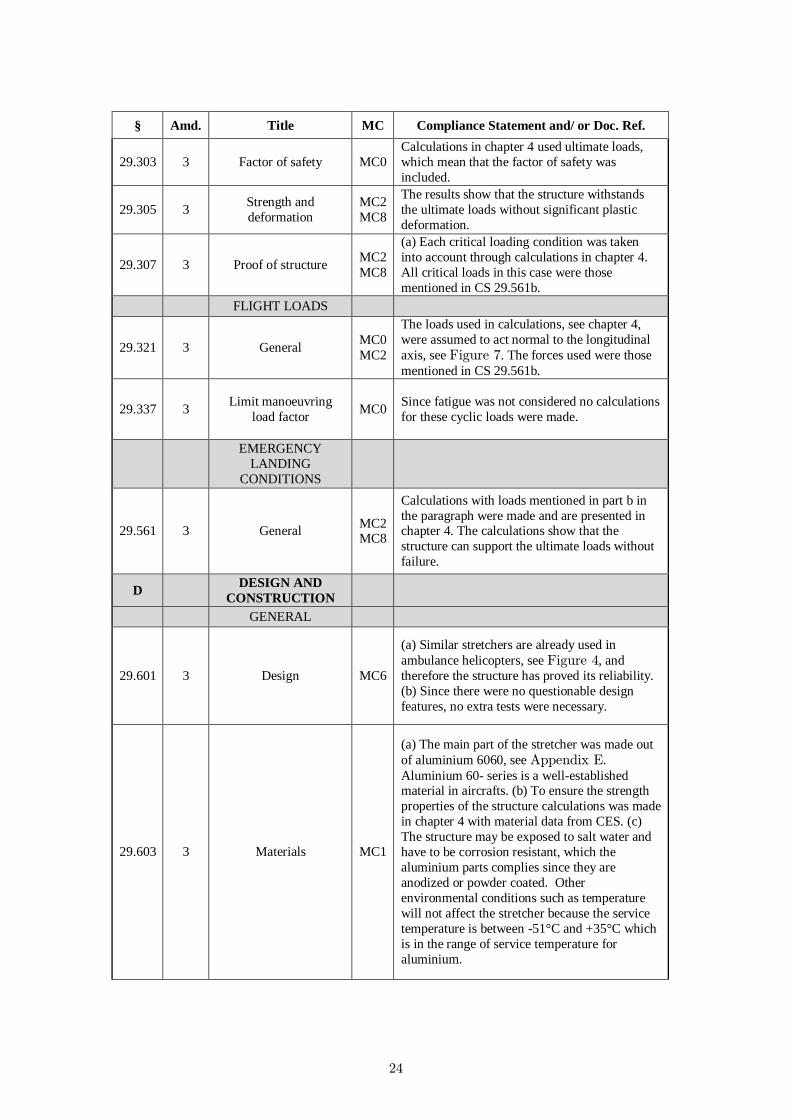
§ Amd. Title MC Compliance Statement and/ or Doc. Ref.
29.303 3 Factor of safety MC0
Calculations in chapter 4 used ultimate loads,
which mean that the factor of safety was
included.
29.305 3 Strength and
deformation
MC2
MC8
The results show that the structure withstands
the ultimate loads without significant plastic
deformation.
29.307 3 Proof of structure MC2
MC8
(a) Each critical loading condition was taken
into account through calculations in chapter 4.
All critical loads in this case were those
mentioned in CS 29.561b.
FLIGHT LOADS
29.321 3 General MC0
MC2
The loads used in calculations, see chapter 4,
were assumed to act normal to the longitudinal
axis, see Figure 7. The forces used were those
mentioned in CS 29.561b.
29.337 3 Limit manoeuvring
load factor MC0
Since fatigue was not considered no calculations
for these cyclic loads were made.
EMERGENCY
LANDING
CONDITIONS
29.561 3 General MC2 MC8
Calculations with loads mentioned in part b in
the paragraph were made and are presented in chapter 4. The calculations show that the
structure can support the ultimate loads without
failure.
D DESIGN AND
CONSTRUCTION
GENERAL
29.601 3 Design MC6
(a) Similar stretchers are already used in
ambulance helicopters, see Figure 4, and
therefore the structure has proved its reliability.
(b) Since there were no questionable design
features, no extra tests were necessary.
29.603 3 Materials MC1
(a) The main part of the stretcher was made out
of aluminium 6060, see Appendix E.
Aluminium 60- series is a well-established material in aircrafts. (b) To ensure the strength
properties of the structure calculations was made
in chapter 4 with material data from CES. (c)
The structure may be exposed to salt water and
have to be corrosion resistant, which the
aluminium parts complies since they are
anodized or powder coated. Other
environmental conditions such as temperature
will not affect the stretcher because the service
temperature is between -51°C and +35°C which
is in the range of service temperature for
aluminium.
25
§ Amd. Title MC Compliance Statement and/ or Doc. Ref.
29.605 3 Fabrication methods MC1
MC2
(a) One pair of the outer attachment was
positioned on a welded part, see Figure 5 and
could therefore be critical. (b) All the fabrication
methods used to produce the stretcher, e.g.
extruding, are well known.
29.607 3 Fasteners MC2
(a) There is no single fastener in the
constructions that can jeopardies the flight
operation, which means that only one locking
device is necessary. (b)The stretcher will be
attached to the cabin floor, which means that it
will be no rotating parts and therefore self-
locking nuts may be used.
29.609 3 Protection of structure MC1
MC2
(a) The bearing parts of the stretcher are
anodized and the seat frame, see the blue parts
in Appendix A, is powder coated. This is made
to improve the corrosion resistance (b) Most of
the structure is made in a way that prevents
water accumulation. Two critical parts, 0024
and 0025, where water could be accumulated
can be found in Appendix H.
29.613 3
Material strength
properties and design
values
MC0
MC2
MC8
(a) As mentioned in compliance with CS 29.603
all the materials used are well known and are
suitable for their purpose. (d) All material data
used in the calculations are given in Appendix E. (e) No materials are unknown for the
helicopter industry and therefore no specimen
tests were necessary.
29.619 3 Special factors MC0 The only needed special factor was the fitting
factor which is described in CS 29.625
29.621 3 Casting factors There are no significant castings on the
stretcher.
29.623 3 Bearing factors The construction does not have any bearings.
29.625 3 Fitting factors MC2
(d) The loads, from CS 29.561b, in the
calculations in chapter 4 were multiplied by a
fitting factor of 1.33 according to part d in the
paragraph.
PERSONNEL AND
CARGO
ACCOMMODATIONS
26
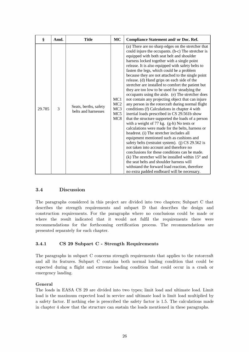
§ Amd. Title MC Compliance Statement and/ or Doc. Ref.
29.785 3 Seats, berths, safety
belts and harnesses
MC1
MC2
MC3
MC5
MC8
(a) There are no sharp edges on the stretcher that
could injure the occupants. (b-c) The stretcher is
equipped with both seat belt and shoulder
harness locked together with a single point
release. It is also equipped with safety belts to
fasten the legs, which could be a problem
because they are not attached to the single point
release. (d) Hand grips on each side of the
stretcher are installed to comfort the patient but
they are too low to be used for steadying the occupants using the aisle. (e) The stretcher does
not contain any projecting object that can injure
any person in the rotorcraft during normal flight
conditions (f) Calculations in chapter 4 with
inertial loads prescribed in CS 29.561b show
that the structure supported the loads of a person
with a weight of 77 kg. (g-h) No tests or
calculations were made for the belts, harness or
headrest. (i) The stretcher includes all
equipment mentioned such as cushions and
safety belts (restraint system). (j) CS 29.562 is not taken into account and therefore no
conclusions for these conditions can be made.
(k) The stretcher will be installed within 15° and
the seat belts and shoulder harness will
withstand the forward load reaction, therefore
no extra padded endboard will be necessary.
3.4 Discussion
The paragraphs considered in this project are divided into two chapters; Subpart C that
describes the strength requirements and subpart D that describes the design and
construction requirements. For the paragraphs where no conclusions could be made or
where the result indicated that it would not fulfil the requirements there were
recommendations for the forthcoming certification process. The recommendations are
presented separately for each chapter.
CS 29 Subpart C - Strength Requirements 3.4.1
The paragraphs in subpart C concerns strength requirements that applies to the rotorcraft
and all its features. Subpart C contains both normal loading condition that could be
expected during a flight and extreme loading condition that could occur in a crash or
emergency landing.
General
The loads in EASA CS 29 are divided into two types; limit load and ultimate load. Limit
load is the maximum expected load in service and ultimate load is limit load multiplied by
a safety factor. If nothing else is prescribed the safety factor is 1.5. The calculations made
in chapter 4 show that the structure can sustain the loads mentioned in these paragraphs.
27
Emergency Landing Conditions
This part describes the loading condition in the worst case scenario; a crash. All occupants
and each item of mass should be restraint in a way that supports 4 g upwards, 16 g
forward, 8 g sideward, 20 g downward and 1.5 g rearward in a crash. The structure has to
be able to support these loading conditions without ultimate failures. The results of the
calculations indicated that the structure would be able to withstand these emergency
landing conditions. The numerical model features the load bearing part of the stretcher and
does not take the interface between the stretcher and the surrounding into account. A draft
of a fixation system for the interface is presented in chapter 5 but it has not been validated
with respect to the strength requirements.
CS 29 Subpart D – Design and Construction 3.4.2
Subpart D includes information about the design features such as materials and fabrication
methods. The paragraphs describe procedures to control the suitability of materials and
new design features and also the safety factors that were used in the calculations.
General
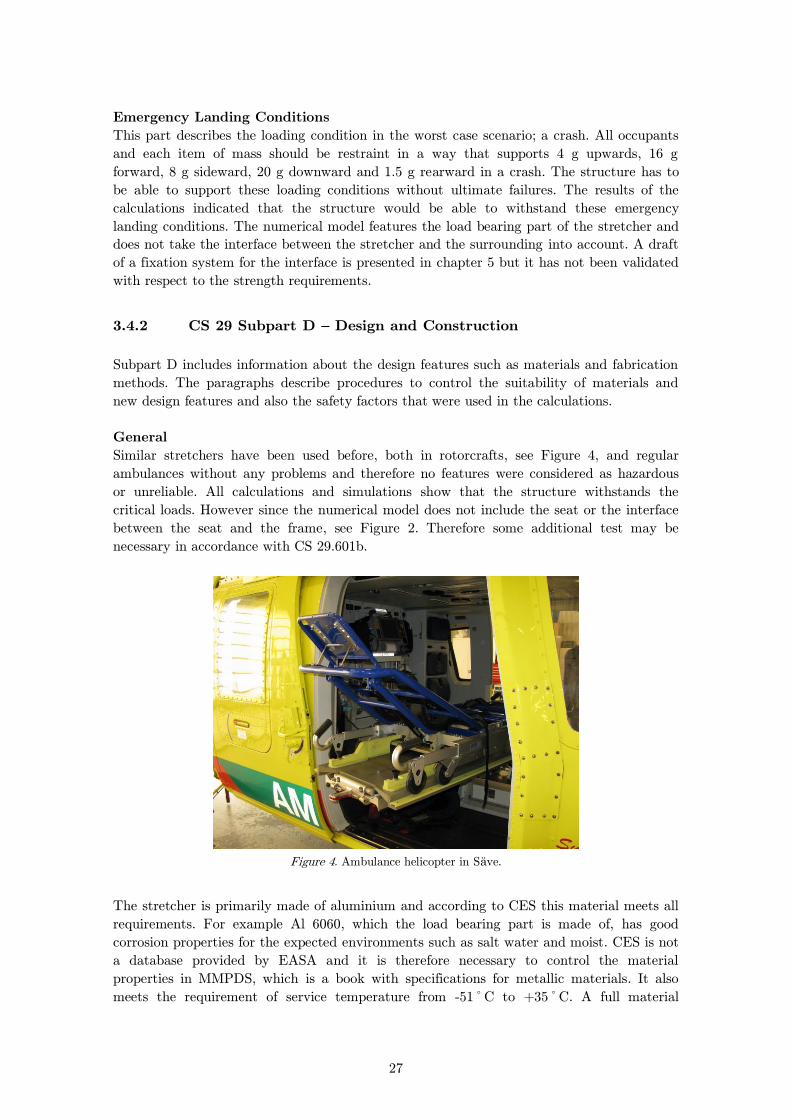
Similar stretchers have been used before, both in rotorcrafts, see Figure 4, and regular
ambulances without any problems and therefore no features were considered as hazardous
or unreliable. All calculations and simulations show that the structure withstands the
critical loads. However since the numerical model does not include the seat or the interface
between the seat and the frame, see Figure 2. Therefore some additional test may be
necessary in accordance with CS 29.601b.
Figure 4. Ambulance helicopter in Säve.
The stretcher is primarily made of aluminium and according to CES this material meets all
requirements. For example Al 6060, which the load bearing part is made of, has good
corrosion properties for the expected environments such as salt water and moist. CES is not
a database provided by EASA and it is therefore necessary to control the material
properties in MMPDS, which is a book with specifications for metallic materials. It also
meets the requirement of service temperature from -51ºC to +35ºC. A full material
28
specification can be found in Appendix E. Another argument that verifies the suitability for
this material is that similar aluminium alloys are commonly used in rotorcrafts with good
results. Although aluminium 6060 meets the material requirements, it will be appropriate to
control the structure at every service time to ensure that the material has not deteriorated.
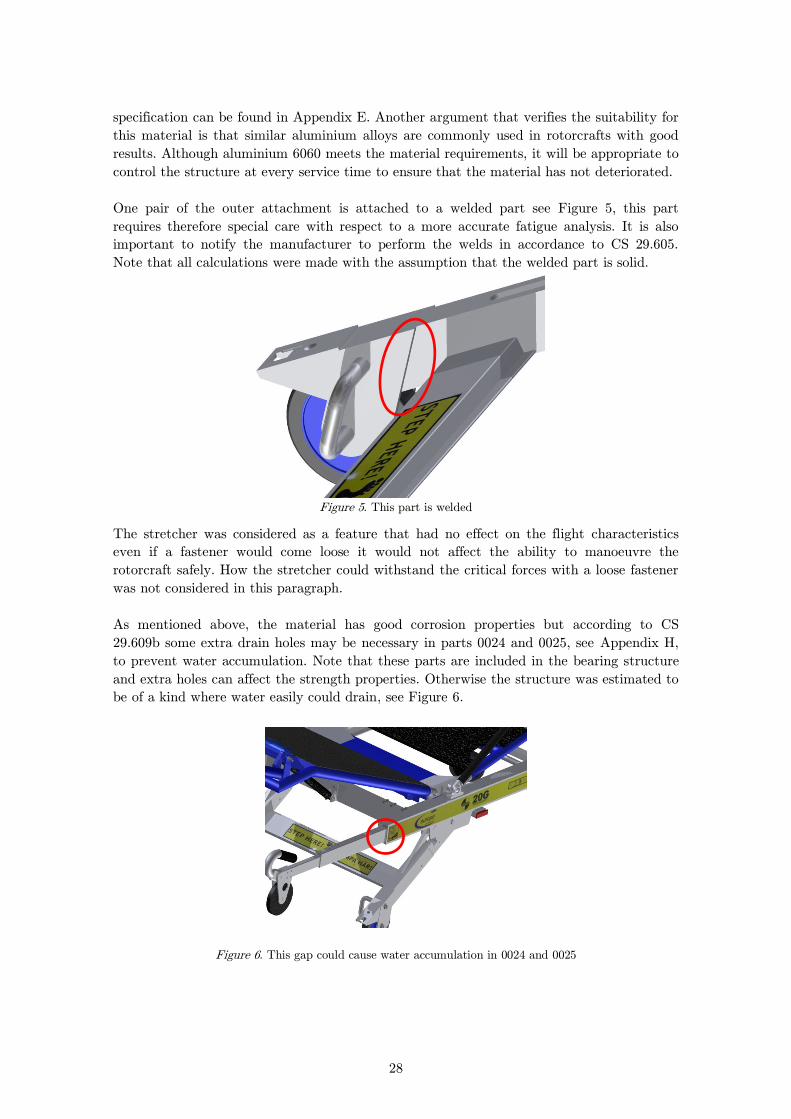
One pair of the outer attachment is attached to a welded part see Figure 5, this part
requires therefore special care with respect to a more accurate fatigue analysis. It is also
important to notify the manufacturer to perform the welds in accordance to CS 29.605.
Note that all calculations were made with the assumption that the welded part is solid.
Figure 5. This part is welded
The stretcher was considered as a feature that had no effect on the flight characteristics
even if a fastener would come loose it would not affect the ability to manoeuvre the
rotorcraft safely. How the stretcher could withstand the critical forces with a loose fastener
was not considered in this paragraph.
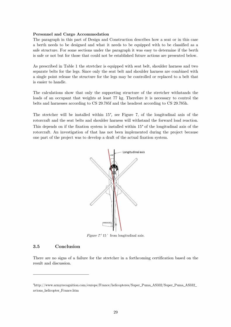
As mentioned above, the material has good corrosion properties but according to CS
29.609b some extra drain holes may be necessary in parts 0024 and 0025, see Appendix H,
to prevent water accumulation. Note that these parts are included in the bearing structure
and extra holes can affect the strength properties. Otherwise the structure was estimated to
be of a kind where water easily could drain, see Figure 6.
Figure 6. This gap could cause water accumulation in 0024 and 0025
29
Personnel and Cargo Accommodation
The paragraph in this part of Design and Construction describes how a seat or in this case
a berth needs to be designed and what it needs to be equipped with to be classified as a
safe structure. For some sections under the paragraph it was easy to determine if the berth
is safe or not but for those that could not be established future actions are presented below.
As prescribed in Table 1 the stretcher is equipped with seat belt, shoulder harness and two
separate belts for the legs. Since only the seat belt and shoulder harness are combined with
a single point release the structure for the legs may be controlled or replaced to a belt that
is easier to handle.
The calculations show that only the supporting structure of the stretcher withstands the
loads of an occupant that weights at least 77 kg. Therefore it is necessary to control the
belts and harnesses according to CS 29.785f and the headrest according to CS 29.785h.
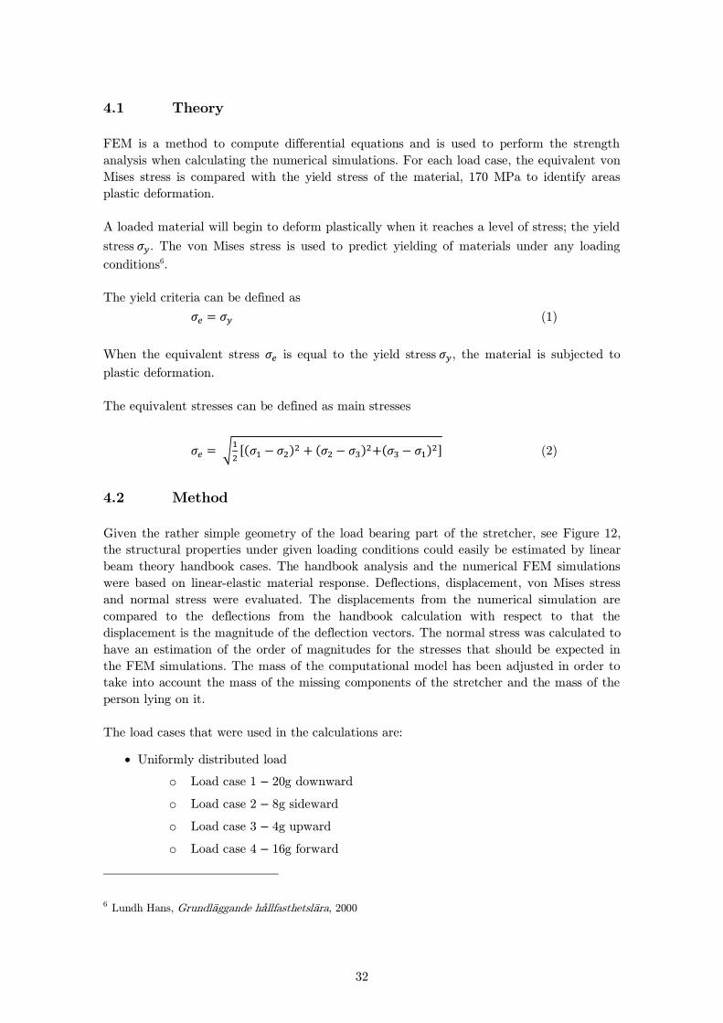
The stretcher will be installed within 15°, see Figure 7, of the longitudinal axis of the
rotorcraft and the seat belts and shoulder harness will withstand the forward load reaction.
This depends on if the fixation system is installed within 15° of the longitudinal axis of the
rotorcraft. An investigation of that has not been implemented during the project because
one part of the project was to develop a draft of the actual fixation system.
Figure 7.4 15º from longitudinal axis.
3.5 Conclusion
There are no signs of a failure for the stretcher in a forthcoming certification based on the
result and discussion.
4http://www.armyrecognition.com/europe/France/helicopteres/Super_Puma_AS332/Super_Puma_AS332_
avions_helicopter_France.htm

30
4 Strength Analysis
To become certified by EASA, there are requirements on the stretcher’s strength that must
be met. This part of the project focused on proving that the stretcher would meet these
requirements and withstand various loads in different directions. The strength analysis is
based on handbook calculations and numerical FEM simulations. It was discussed whether
the stretcher would be approved for use in helicopters or if adjustments are needed.
The paragraphs CS 29.301, CS 29.561 and CS 29.625 in EASA are relevant for structural
analysis. According to CS 29.301 limit load and ultimate loading conditions have to be
considered. Under limit loading conditions, the structure shall not undergo plastic
deformation and under ultimate loading conditions the structure shall not buckle or
undergo ultimate failure. The ultimate loads are the maximum loads that the beam can be
subjected to. Therefore only the ultimate load is considered for the strength analysis. If the
structure would show plastic deformation for ultimate loads the case would have to be
studied for whether the beam would buckle or be subjected to ultimate failure and checked
against any plastic deformation when subjected to limit loads.
According to CS 29.561 the stretcher must be designed to handle ultimate inertial load
factors in a crash landing, see Figure 8. The directions of the loads are shown in Figure 9,
Figure 10 and Figure 11. The stretcher will not be subjected to the loads at the same time
and the figures only describe the direction.
Figure 8. The paragraph CS 29.561, section (b)
According to CS 29.625 the inertia forces prescribed in CS 29.561b must be multiplied by a
fitting factor of 1.33 ( ). See equation (7).
CS 29.561 (b)
The structure must be designed to give each occupant every reasonable
chance of escaping serious injury in a crash landing when:
(1) Proper use is made of seats, belts, and other safety design provisions;
(2) The wheels are retracted (where applicable); and
(3) Each occupant and each item of mass inside the cabin that could injure
an occupant is restrained when subjected to the following ultimate inertial
load factors relative to the surrounding structure:
(i) Upward 4 g
(ii) Forward 16 g
(iii) Sideward 8 g
(iv) Downward 20 g, after the intended displacement of the seat device
(v) Rearward 1.5 g

31
Figure 9 5. The helicopter and stretcher in direction x,y
Figure 10 6. The helicopter and stretcher in direction z,x
Figure 11 6. The helicopter and stretcher in direction z,y
5http://www.armyrecognition.com/europe/France/helicopteres/Super_Puma_AS332/Super_Puma_AS332_
avions_helicopter_France.htm
8g 8g
16g
1.5g
x
y
20g
4g
16g 1.5g
z
x
20g
4g
8g 8g
z
y
32
4.1 Theory
FEM is a method to compute differential equations and is used to perform the strength
analysis when calculating the numerical simulations. For each load case, the equivalent von
Mises stress is compared with the yield stress of the material, 170 MPa to identify areas
plastic deformation.
A loaded material will begin to deform plastically when it reaches a level of stress; the yield
stress . The von Mises stress is used to predict yielding of materials under any loading
conditions6.
The yield criteria can be defined as
(1)
When the equivalent stress is equal to the yield stress , the material is subjected to
plastic deformation.
The equivalent stresses can be defined as main stresses
√
[( ) ( ) ( ) ] (2)
4.2 Method
Given the rather simple geometry of the load bearing part of the stretcher, see Figure 12,
the structural properties under given loading conditions could easily be estimated by linear
beam theory handbook cases. The handbook analysis and the numerical FEM simulations
were based on linear-elastic material response. Deflections, displacement, von Mises stress
and normal stress were evaluated. The displacements from the numerical simulation are
compared to the deflections from the handbook calculation with respect to that the
displacement is the magnitude of the deflection vectors. The normal stress was calculated to
have an estimation of the order of magnitudes for the stresses that should be expected in
the FEM simulations. The mass of the computational model has been adjusted in order to
take into account the mass of the missing components of the stretcher and the mass of the
person lying on it.
The load cases that were used in the calculations are:
Uniformly distributed load
o Load case 1 – 20g downward
o Load case 2 – 8g sideward
o Load case 3 – 4g upward
o Load case 4 – 16g forward
6 Lundh Hans, Grundläggande hållfasthetslära, 2000
33
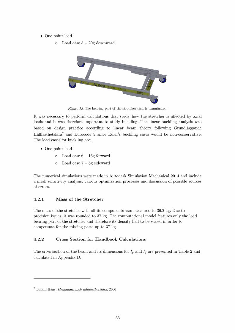
One point load
o Load case 5 – 20g downward
Figure 12. The bearing part of the stretcher that is examinated.
It was necessary to perform calculations that study how the stretcher is affected by axial
loads and it was therefore important to study buckling. The linear buckling analysis was
based on design practice according to linear beam theory following Grundläggande
Hållfasthetslära7 and Eurocode 9 since Euler’s buckling cases would be non-conservative.
The load cases for buckling are:
One point load
o Load case 6 – 16g forward
o Load case 7 – 8g sideward
The numerical simulations were made in Autodesk Simulation Mechanical 2014 and include
a mesh sensitivity analysis, various optimisation processes and discussion of possible sources
of errors.
Mass of the Stretcher 4.2.1
The mass of the stretcher with all its components was measured to 36.2 kg. Due to
precision issues, it was rounded to 37 kg. The computational model features only the load
bearing part of the stretcher and therefore its density had to be scaled in order to
compensate for the missing parts up to 37 kg.
Cross Section for Handbook Calculations 4.2.2
The cross section of the beam and its dimensions for and are presented in Table 2 and
calculated in Appendix D.
7 Lundh Hans, Grundläggande hållfasthetslära, 2000

34
Figure 13. The cross section of the main beam divided in parts.
∑ (3)
(4)
The cross-section of the joist is given in Figure 14.
Figure 14. The cross section of the joist
(5)
Table 2 summarises cross-sectional data and material properties.
29 15,5
4.5
49
2.5 2.5
30
53
2.5
y-axis
z-axis
y-axis
z-axis
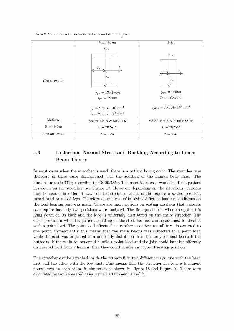
35
Table 2. Materials and cross sections for main beam and joist.
Main beam Joist
Cross section
Material SAPA EN AW 6060 T6 SAPA EN AW 6060 F22.T6
E-modulus
Poisson’s ratio ʋ = 0.33 ʋ = 0.33
4.3 Deflection, Normal Stress and Buckling According to Linear
Beam Theory
In most cases when the stretcher is used, there is a patient laying on it. The stretcher was
therefore in these cases dimensioned with the addition of the human body mass. The
human’s mass is 77kg according to CS 29.785g. The most ideal case would be if the patient
lies down on the stretcher, see Figure 17. However, depending on the situations, patients
may be seated in different ways on the stretcher which might require a seated position,
raised head or raised legs. Therefore an analysis of implying different loading conditions on
the load bearing part was made. There are many options on seating positions that patients
can require but only two positions were analysed. The first position is when the patient is
lying down on its back and the load is uniformly distributed on the entire stretcher. The
other position is when the patient is sitting on the stretcher and can be assumed to affect it
with a point load. The point load affects the stretcher most because all force is centered to
one point. Consequently this means that the main beams was subjected to a point load
while the joist was subjected to a uniformly distributed load but only for joist beneath the
buttocks. If the main beams could handle a point load and the joist could handle uniformly
distributed load from a human; then they could handle any type of seating position.
The stretcher can be attached inside the rotorcraft in two different ways, one with the head
first and the other with the feet first. This means that the stretcher has four attachment
points, two on each beam, in the positions shown in Figure 18 and Figure 20. These were
calculated as two separated cases named attachment 1 and 2.
y
z
yTP
zTP
y
z
yTP
zTP
36
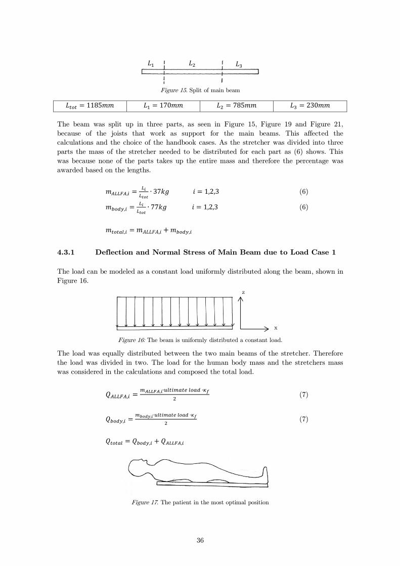
Figure 15. Split of main beam
The beam was split up in three parts, as seen in Figure 15, Figure 19 and Figure 21,
because of the joists that work as support for the main beams. This affected the
calculations and the choice of the handbook cases. As the stretcher was divided into three
parts the mass of the stretcher needed to be distributed for each part as (6) shows. This
was because none of the parts takes up the entire mass and therefore the percentage was
awarded based on the lengths.
(6)
(6)
Deflection and Normal Stress of Main Beam due to Load Case 1 4.3.1
The load can be modeled as a constant load uniformly distributed along the beam, shown in
Figure 16.
Figure 16: The beam is uniformly distributed a constant load.
The load was equally distributed between the two main beams of the stretcher. Therefore
the load was divided in two. The load for the human body mass and the stretchers mass
was considered in the calculations and composed the total load.
(7)
(7)
Figure 17. The patient in the most optimal position
𝐿 𝐿 𝐿
z
x
37
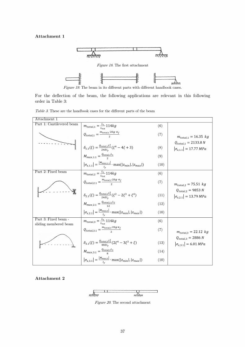
Attachment 1
Figure 18. The first attachment
Figure 19. The beam in its different parts with different handbook cases.
For the deflection of the beam, the following applications are relevant in this following
order in Table 3:
Table 3. These are the handbook cases for the different parts of the beam
Attachment 1
Part 1: Cantilevered beam
(6)
(7)
( )
( ) (8)
(9)
| | | |
(| | | |) (10)
| |
Part 2: Fixed beam
(6)
(7)
( )
( ) (11)
(12)
| | | |
(| | | |) (10)
| |
Part 3: Fixed beam -
sliding membered beam
(6)
(7)
( )
( ) (13)
(14)
| | | |
(| | | |) (10)
| |
Attachment 2
Figure 20. The second attachment
38
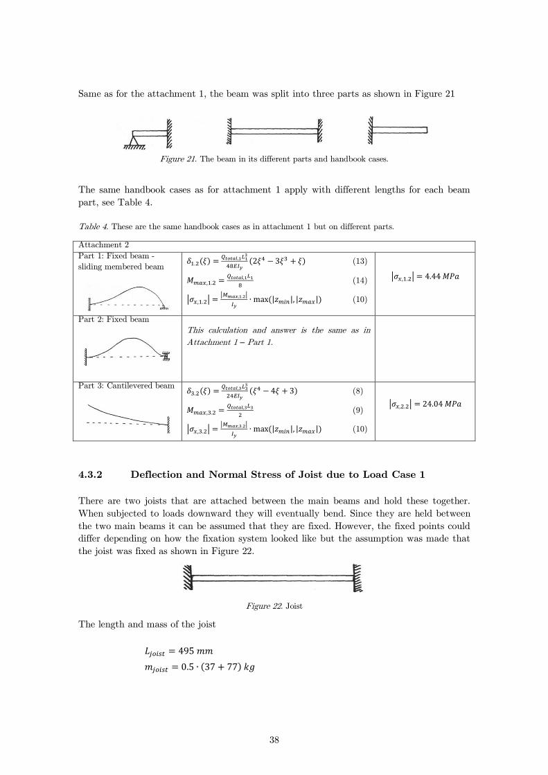
Same as for the attachment 1, the beam was split into three parts as shown in Figure 21
Figure 21. The beam in its different parts and handbook cases.
The same handbook cases as for attachment 1 apply with different lengths for each beam
part, see Table 4.
Table 4. These are the same handbook cases as in attachment 1 but on different parts.
Attachment 2
Part 1: Fixed beam -
sliding membered beam
( )
( ) (13)
(14)
| | | |
(| | | |) (10)
| |
Part 2: Fixed beam
This calculation and answer is the same as in
Attachment 1 – Part 1.
Part 3: Cantilevered beam
( )
( ) (8)
(9)
| | | |
(| | | |) (10)
| |
Deflection and Normal Stress of Joist due to Load Case 1 4.3.2
There are two joists that are attached between the main beams and hold these together.
When subjected to loads downward they will eventually bend. Since they are held between
the two main beams it can be assumed that they are fixed. However, the fixed points could
differ depending on how the fixation system looked like but the assumption was made that
the joist was fixed as shown in Figure 22.
Figure 22. Joist
The length and mass of the joist
( )

39
The mass for the whole stretcher is 37kg and the joists would in reality not alone be
subjected to the entire mass. The load would be distributed over both the joists and the
main beams. For these calculations the two joists were subjected to loads calculated with
half of the mass since it would be closer to the maximum loads they supposed to manage.
The calculations for the deflection of the joist are shown in Table 5.
Table 5. The deflection of the joist
Joist
Fixed beam
( )
( ) (11)
(12)
| | | |
(| | | |) (10)
| |
Deflection and Normal Stress of Main Beam due to Load Case 2 4.3.3
For the deflection of the beam sideward, the handbook cases are the same. The difference
was that the cases considered bending round the z-axis. For this case, the direction of the
load is sideward and is described in Figure 9 and Figure 10. Figure 23 below shows the
principle for how the beam is subjected to the load. The different calculations are presented
in Table 6 and Table 7.
Figure 23. A simplified sketch for the direction of the load.
Attachment 1
Table 6. The handbook cases for the beam in attachment 1
Attachment 1 - sideward Part 1: Cantilevered beam
(7)
( )
( ) (8)
(9)
| | | |
(| | | |) (10)
| |
Part 2: Fixed beam
(7)
( )
( ) (11)
(12)
| | | |
(| | | |) (10)
| |
y
x
z

40
Part 3: Fixed beam -
sliding membered beam
(7)
( )
( ) (13)
(14)
| | | |
(| | | |) (10)
| |
Attachment 2
Table 7. The differences for attachment 2
Attachment 2 - sideward
Part 1: Fixed beam -
sliding membered beam
( )
( ) (13)
(14)
| | | |
(| | | |) (10)
| |
Part 2: Fixed beam
This calculation and answer is the same as in
attachment 1.
Part 3: Cantilevered beam
( )
( ) (8)
(9)
| | | |
(| | | |) (10)
| |
One Point Load due to Load Case 5 4.3.4
In this case the patient would sit with the head and legs raised from the seat, see Figure 24.
The weight from the human is centered at one point, at the buttocks. This is the worst case
when the beam is loaded in only one place. This case was studied for both the main beam
and the joist. The case with the joist was calculated with the assumption that the loads
from the human and the stretcher itself were subjected to it as a uniformly distributed load,
but only for the joist beneath the buttocks. In reality the joist is not directly underneath
the buttocks, and was scaled as described below. If the deflection is non-critical it would
show that the joist withstands any kind of seating because in reality it would never be
subjected to such loads.
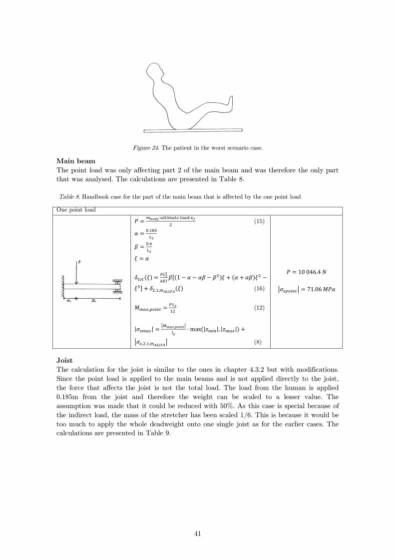
41
Figure 24. The patient in the worst scenario case.
Main beam
The point load was only affecting part 2 of the main beam and was therefore the only part
that was analysed. The calculations are presented in Table 8.
Table 8. Handbook case for the part of the main beam that is affected by the one point load
One point load
(15)
( )
[( ) ( )
] ( ) (16)
(12)
| | | |
(| | | |)
| | (8)
| |
Joist
The calculation for the joist is similar to the ones in chapter 4.3.2 but with modifications.
Since the point load is applied to the main beams and is not applied directly to the joist,
the force that affects the joist is not the total load. The load from the human is applied
0.185m from the joist and therefore the weight can be scaled to a lesser value. The
assumption was made that it could be reduced with 50%. As this case is special because of
the indirect load, the mass of the stretcher has been scaled 1/6. This is because it would be
too much to apply the whole deadweight onto one single joist as for the earlier cases. The
calculations are presented in Table 9.
42
Table 9. Handbook case for the joist that is affected by the one point load
Joist – Uniformly distributed load
Fixed beam
(
) (7)
( )
( ) (11)
(12)
| | | |
(| | | |) (10)
| |
Buckling 4.3.5
According to EASA, CS 29, it is required that the beams will not buckle when they are
subjected to ultimate loads. To show that the beams are suitable, the critical load - had
to be calculated by using Euler’s buckling cases and then compared to the ultimate loads.
The loads are assumed to be one point loads affecting the center of gravity. If these were
greater than, , the beam would buckle which is not acceptable.8 It must be taken into
account that the beam will normally buckle earlier in reality than what linear buckling
predicts. Therefore, design practices that compensate for this must be followed.
These calculations were made with the total mass of 114kg with the forward acceleration
16g, affecting the main beams, and for the sideward acceleration 8g, affecting the joists.
Buckling for the Main Beams due to Load Case 4
To determinate that the requirements were met it was compulsory to study three different
buckling cases that depended on the attachment. Given that the fixation system was not
developed it was necessary to study each of these three cases and not only the worst.
The calculations were only made for attachment 1, see Figure 18. This was because if the
calculations show that the beams will not buckle for these cases the other cases for
attachment 2, see Figure 20, is similar enough that the assumption could be made that
these would not buckle either.
The procedure for design practice on how was determined is as follows:
The force that occurs from the acceleration 16g on the main beams is
(7)
Buckling stress for plastic deformation is defined as
8 Lundh Hans, Grundläggande hållfasthetslära, 2000
43
(17)
The free buckling length for Euler buckling is defined as
(18)
The free buckling length takes the elasticity of the fixed attachments into
consideration and can be found in table 69. Free buckling length of the Euler buckling
differs for different Euler cases. can also be found in the same table.
The slenderness ratio must be found to determinate the buckling stress . The slenderness
ratio is defined as:
(19)
Where is the cross section radius of gyration is given by:
√
(20)
Cross section area
Moment of Inertia
is found in figure 17.310 with the slenderness ratio for aluminum alloy.
(21)
To show that buckling does not occur for the case this must apply:
(22)
9 Lundh Hans, Grundläggande hållfasthetslära, 2000 10 Sundström, Bengt. Handbok och Formelsamling i hållfasthetslära, 1998
44
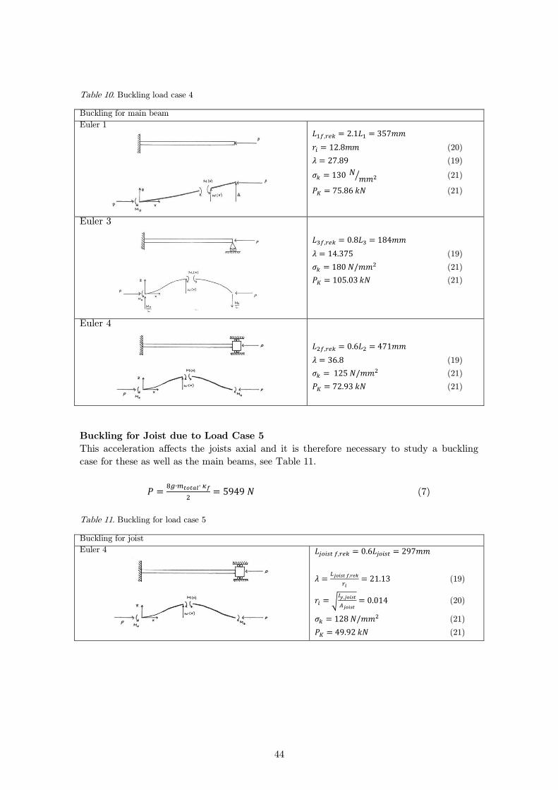
Table 10. Buckling load case 4
Buckling for main beam
Euler 1
(20)
(19)
⁄ (21)
(21)
Euler 3
(19)
(21)
(21)
Euler 4
(19)
(21)
(21)
Buckling for Joist due to Load Case 5
This acceleration affects the joists axial and it is therefore necessary to study a buckling
case for these as well as the main beams, see Table 11.
(7)
Table 11. Buckling for load case 5
Buckling for joist
Euler 4
(19)
√
(20)
(21)
(21)
45
4.4 Buckling According to Eurocode 9
When a strength analysis is performed, it is essential to look at how loads will affect the
design and how it will meet the requirements that are set. Eurocode 9 was used to check
the various buckling cases. This is useful when studying how flexural buckling and lateral
torsional buckling influence the beam. What differ these calculations from the previous ones
is the additional use of factors that take into account the imperfections that occur in
aluminum structures. These cases consider checking members that are subjected to a
combination of axial force and major axis or minor axis bending. 11
Eurocode 9 describes how to perform a buckling check. This indicates whether a specific
value is greater or lesser than one, if the value is greater than one the stretcher is
considered unsafe but if the value is lesser than one; it is considered safe. At first the cross
section was classified, by defining a beta factor that depends on the length and thickness of
the cross sections. Some factors compensate for whether the material is heat-treated or
welded. Considering members that are subjected to compressive forces may have reduced
resistance because of local buckling of slender elements. It is therefore important to
calculate reductions factors that increased with flexural buckling and lateral-torsional
buckling. All of this was then used in the buckling check that determined if the stretcher
was safe or not:
(
)
((
)
(
)
)
(23)
A buckling check for the main beam and the joist is presented in Appendix D.
4.5 Numerical Simulation
Below follows a step by step description on how the numerical simulations were done and
which assumptions that were made.
3D-Model 4.5.1
The computational model, see Figure 25, features only the load bearing part of the
stretcher with the most necessary parts. Parts that do not contribute to stiffness properties
were removed from the load bearing part to make the simulations more effective.
11 British Standards Institution, Eurocode 9, DD ENV 1999-1-1:2000

46
Figure 25. 3D-dummy model
Loads and Boundary Conditions 4.5.2
The densities of the different materials were increased with a factor so that the models
mass was equal to the mass of the stretcher with all its components including the person
mass. The calculations below show how the density of the computational model was scaled
to take into account missing parts and person mass.
(24)
is the density without humans mass.
( )
(25)
is the new density with the factor of
( )
For the case with one point load the main beams were loaded with nodal forces as seen in
Figure 26.
Figure 26. The arrows show where the nodal forces were applied.
Another assumption was that the boundary conditions were set as fixed on the joints that
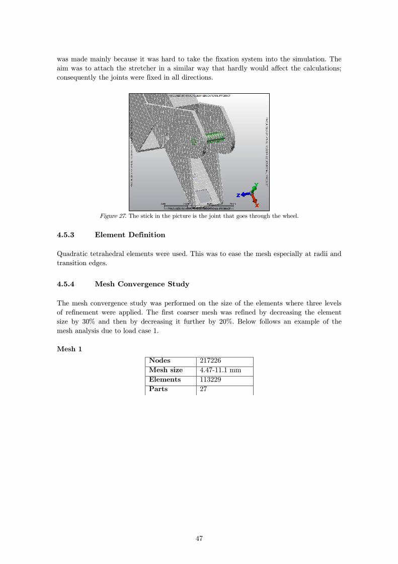
go through the wheels of the stretcher, see Figure 27. This is not how it looks like in reality
because these four points will never be attached on the fixation system. This assumption
47
was made mainly because it was hard to take the fixation system into the simulation. The
aim was to attach the stretcher in a similar way that hardly would affect the calculations;
consequently the joints were fixed in all directions.
Figure 27. The stick in the picture is the joint that goes through the wheel.
Element Definition 4.5.3
Quadratic tetrahedral elements were used. This was to ease the mesh especially at radii and
transition edges.
Mesh Convergence Study 4.5.4
The mesh convergence study was performed on the size of the elements where three levels
of refinement were applied. The first coarser mesh was refined by decreasing the element
size by 30% and then by decreasing it further by 20%. Below follows an example of the
mesh analysis due to load case 1.
Mesh 1
Nodes 217226
Mesh size 4.47-11.1 mm
Elements 113229
Parts 27
48
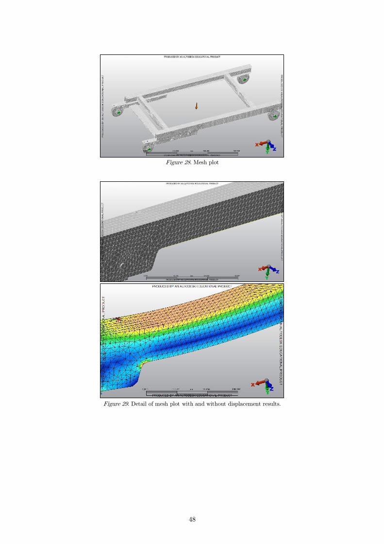
Figure 28. Mesh plot
Figure 29. Detail of mesh plot with and without displacement results.
49
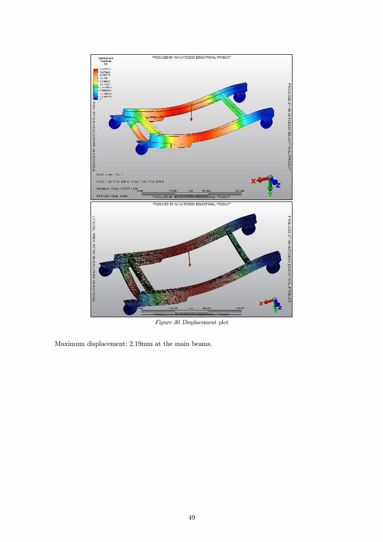
Figure 30. Displacement plot
Maximum displacement: 2.19mm at the main beams.

50
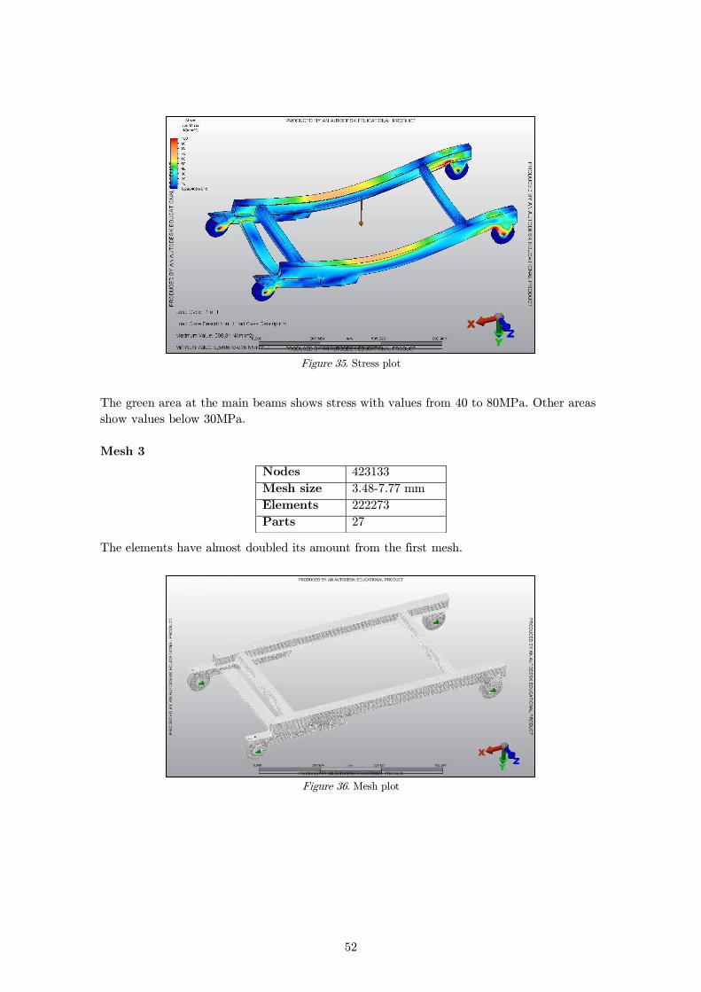
Figure 31. Stress plot
Stresses at the main beams show values from 30 to 70MPa. Other areas show values below
30MPa.
Mesh 2
The elements have now increased with 30% from previous mesh.
Nodes 326124
Mesh size 4.0-9.1 mm
Elements 170834
Parts 27
51
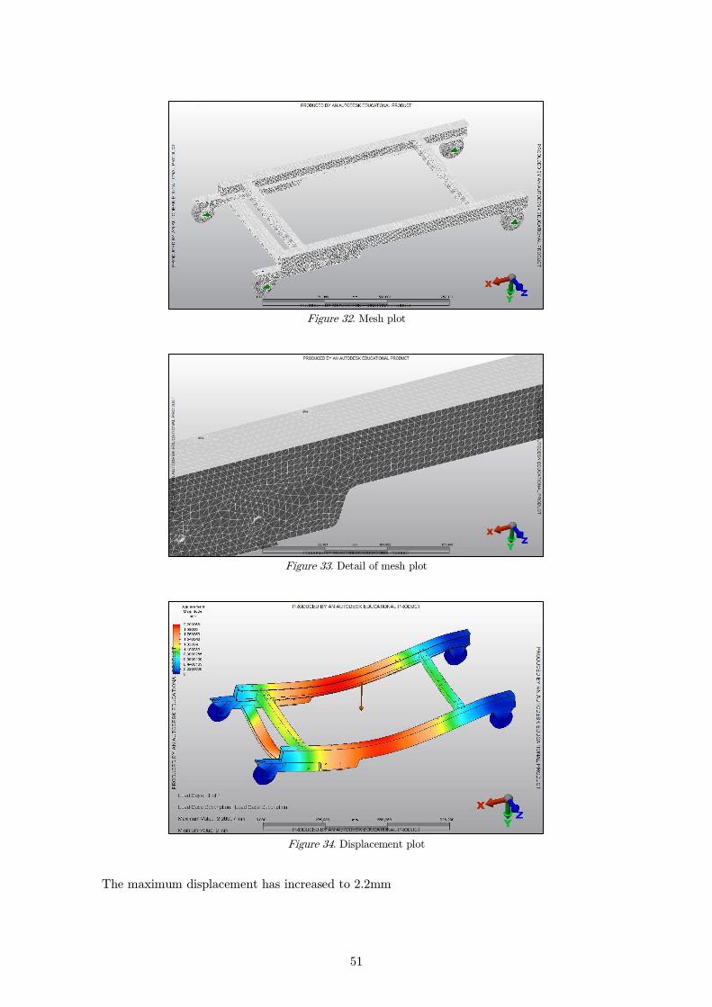
Figure 32. Mesh plot
Figure 33. Detail of mesh plot
Figure 34. Displacement plot
The maximum displacement has increased to 2.2mm
52
Figure 35. Stress plot
The green area at the main beams shows stress with values from 40 to 80MPa. Other areas
show values below 30MPa.
Mesh 3
The elements have almost doubled its amount from the first mesh.
Figure 36. Mesh plot
Nodes 423133
Mesh size 3.48-7.77 mm
Elements 222273
Parts 27
53
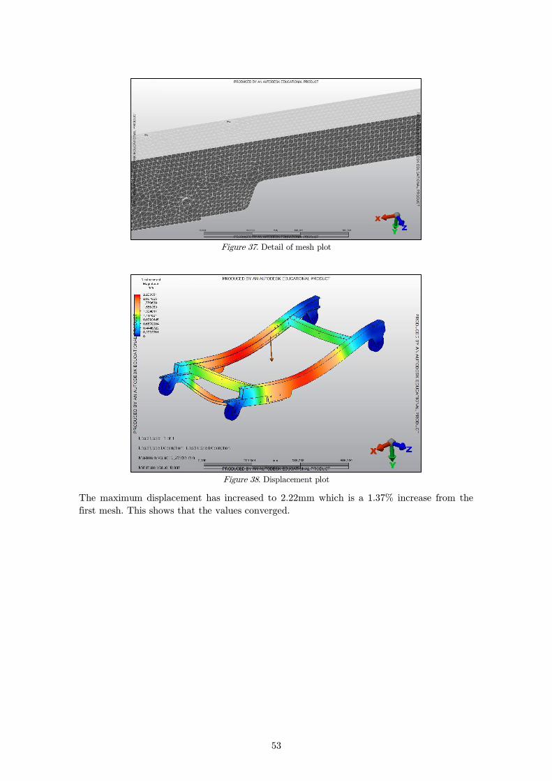
Figure 37. Detail of mesh plot
Figure 38. Displacement plot
The maximum displacement has increased to 2.22mm which is a 1.37% increase from the
first mesh. This shows that the values converged.
54
Figure 39. Stress plot
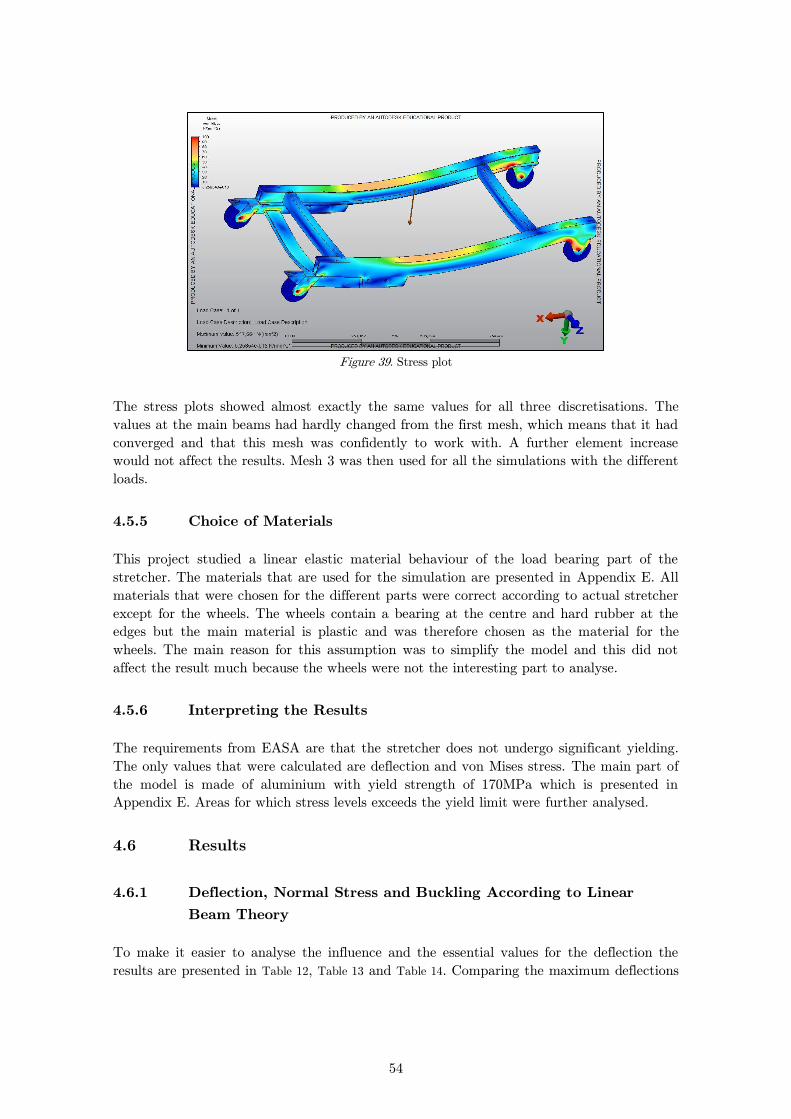
The stress plots showed almost exactly the same values for all three discretisations. The
values at the main beams had hardly changed from the first mesh, which means that it had
converged and that this mesh was confidently to work with. A further element increase
would not affect the results. Mesh 3 was then used for all the simulations with the different
loads.
Choice of Materials 4.5.5
This project studied a linear elastic material behaviour of the load bearing part of the
stretcher. The materials that are used for the simulation are presented in Appendix E. All
materials that were chosen for the different parts were correct according to actual stretcher
except for the wheels. The wheels contain a bearing at the centre and hard rubber at the
edges but the main material is plastic and was therefore chosen as the material for the
wheels. The main reason for this assumption was to simplify the model and this did not
affect the result much because the wheels were not the interesting part to analyse.
Interpreting the Results 4.5.6
The requirements from EASA are that the stretcher does not undergo significant yielding.
The only values that were calculated are deflection and von Mises stress. The main part of
the model is made of aluminium with yield strength of 170MPa which is presented in
Appendix E. Areas for which stress levels exceeds the yield limit were further analysed.
4.6 Results
Deflection, Normal Stress and Buckling According to Linear 4.6.1
Beam Theory
To make it easier to analyse the influence and the essential values for the deflection the
results are presented in Table 12, Table 13 and Table 14. Comparing the maximum deflections

55
can provide conclusions considering the stiffness of the structure. The stresses are presented
for comparison with the numerical simulation analysis.
The results for buckling are presented in data tables. For buckling according to linear beam
theory the value for is the greatest value allowed before the beam would buckle. The
value is the calculated load that the beam is subjected to. Comparing these to each other
show if is greater than , and if that is the case, it would be safe against buckling.
To illustrate the maximum deflection of the handbook calculations which occurred due to
load case 2 for attachment 2 in Part 2, fixed beam, it is presented in Figure 40.
Figure 40. Maximum deflection for handbook calculation.
Table 12. Deflection and Normal Stress due to Load Case 1
Main Beam Deflection and normal
stress
Attachment 1 - Part 1: Cantilevered Beam
| |
Attachment 1 - Part 2: Fixed Beam
| |
Attachment 1 - Part 3: Fixed Beam – Sliding Membered
Beam
| |
Attachment 2 – Part 1: Fixed Beam – Sliding Membered
Beam
| |
Attachment 2 – Part 2: Fixed Beam
| |
Attachment 2 – Part 3: Cantilevered Beam
| |

56
Joist Deflection and normal
stress
| |
Table 13. Deflection and Normal Stress due to Load Case 2
Main Beam Deflection and normal
stress
Attachment 1 - Part 1: Cantilevered Beam
| |
Attachment 1 - Part 2: Fixed Beam
| |
Attachment 1 - Part 3: Fixed Beam – Sliding Membered
Beam
| |
Attachment 2 – Part 1: Fixed Beam – Sliding Membered
Beam
| |
Attachment 2 – Part 2: Fixed Beam
| |
Attachment 2 – Part 3: Cantilevered Beam
| |
Table 14. One Point Load due to Load Case 5
Main beam Deflection and stress
| |
Joist Deflection and stress
| |
Buckling
Table 15. The table shows if P˂Pk
Main beam - Euler 1 Yes
Main beam - Euler 3 Yes
Main beam - Euler 4 Yes
Joist - Euler 4 Yes
As shown in Table 15 there is no risk for buckling for any of the cases.

57
Eurocode 9 4.6.2
Buckling
For buckling according to Eurocode 9 a buckling check was performed. The value in Table
16 is the value calculated from the buckling check. If the value is greater than or equal to
one the beam is considered unsafe but if the value is less than one the beam is considered
safe.
Table 16. The table shows if the beam is safe or unsafe.
Value Safe?
Main beam - Euler 1 0.55 Yes
Main beam - Euler 2 0.55 Yes
Main beam - Euler 3 0.7 Yes
Joist - Euler 4 0.48 Yes
Numerical Simulation 4.6.3
The results of the numerical simulations are presented here. Equivalent von Mises stress
values are compared with the yield strength of the material, 170Mpa.
Displacement and Stress due to Load Case 1
Table 17. Applied force
Acceleration due to body force 9814.56 mm/s2
X multiplier 0
Y multiplier 26.60
Z multiplier 0
The multiplier is defined as:

58
Figure 41. Displacement plot
Maximum displacement: 2.22mm at the main beams.
Figure 42. Stress plot
The von Mises stress in the structure is mainly between 30 and 80Mpa. Stress
concentration areas (in which the equivalent von Mises stress exceeds the yield limit)
appear in the following locations:

59
Figure 43. The stress around the hole is 255MPa
Figure 44. The stress at the sharp edges is 312MPa
Figure 45. There are trails that run through the bottom of the main beams. The stress values at these
trails are near 550MPa.
Displacement and Stress due to Load Case 2
Table 18. Applied load
Acceleration due to body force 9814.56 mm/s2
X multiplier 0
Y multiplier 0
Z multiplier 10.64
The multiplier is defined as:
60
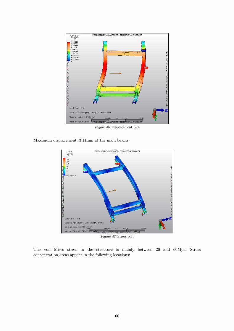
Figure 46. Displacement plot
Maximum displacement: 3.11mm at the main beams.
Figure 47. Stress plot
The von Mises stress in the structure is mainly between 20 and 60Mpa. Stress
concentration areas appear in the following locations:
61
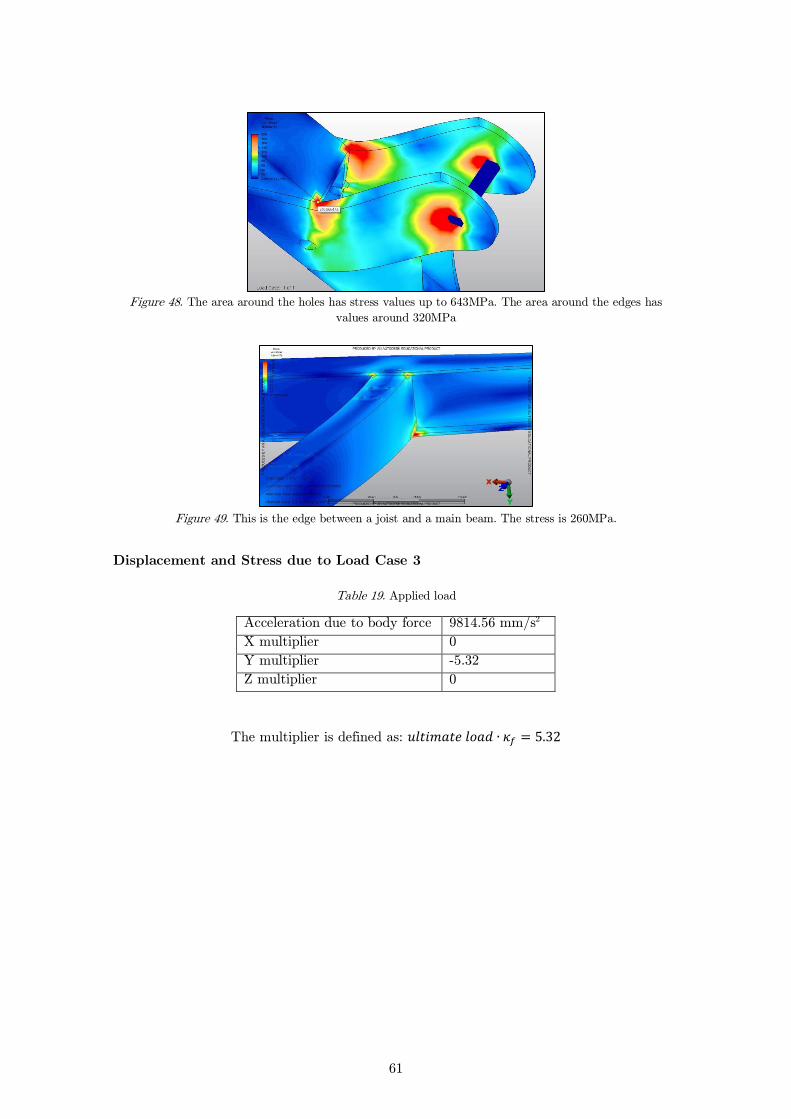
Figure 48. The area around the holes has stress values up to 643MPa. The area around the edges has
values around 320MPa
Figure 49. This is the edge between a joist and a main beam. The stress is 260MPa.
Displacement and Stress due to Load Case 3
Table 19. Applied load
Acceleration due to body force 9814.56 mm/s2
X multiplier 0
Y multiplier -5.32
Z multiplier 0
The multiplier is defined as:
62
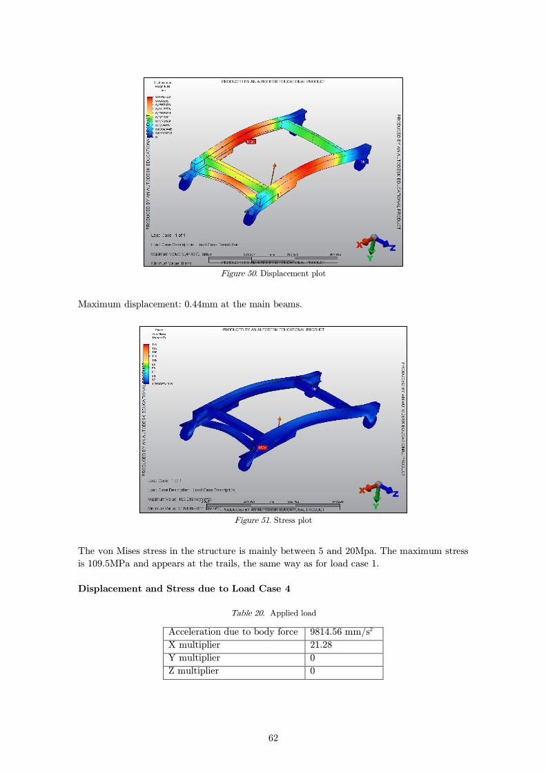
Figure 50. Displacement plot
Maximum displacement: 0.44mm at the main beams.
Figure 51. Stress plot
The von Mises stress in the structure is mainly between 5 and 20Mpa. The maximum stress
is 109.5MPa and appears at the trails, the same way as for load case 1.
Displacement and Stress due to Load Case 4
Table 20. Applied load
Acceleration due to body force 9814.56 mm/s2
X multiplier 21.28
Y multiplier 0
Z multiplier 0
63
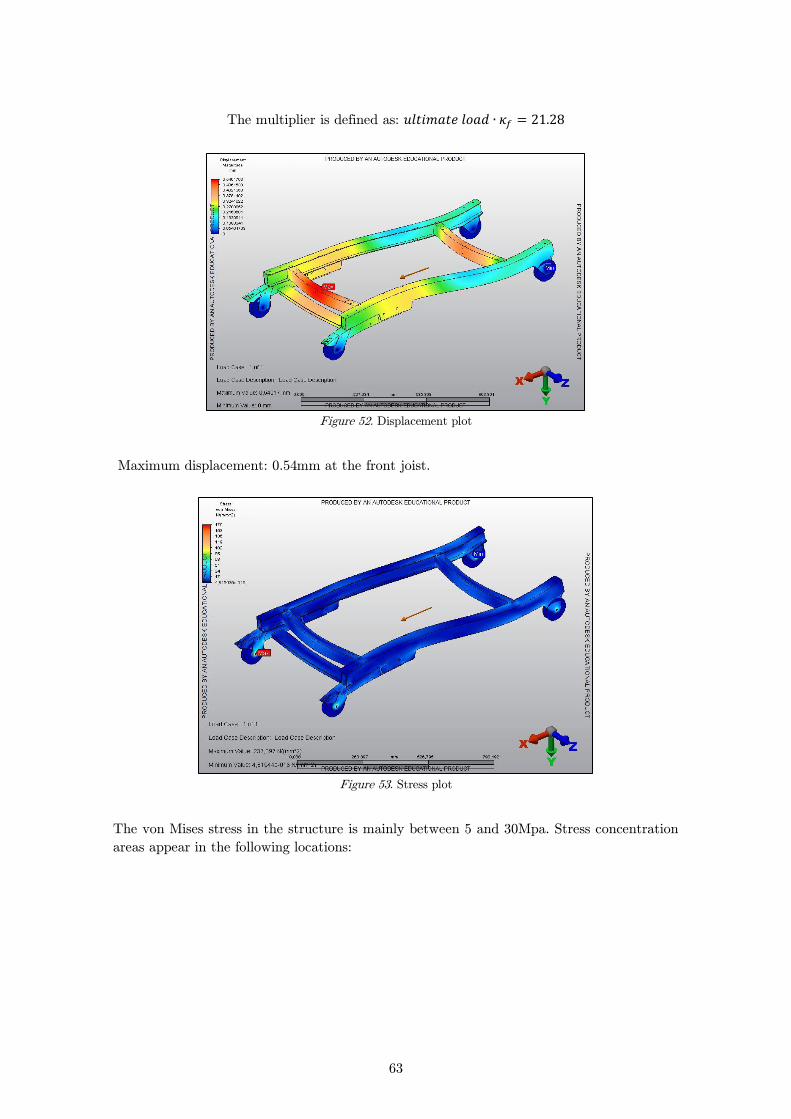
The multiplier is defined as:
Figure 52. Displacement plot
Maximum displacement: 0.54mm at the front joist.
Figure 53. Stress plot
The von Mises stress in the structure is mainly between 5 and 30Mpa. Stress concentration
areas appear in the following locations:

64
Figure 54. The stress around the hole is 234MPa, which is the maximum stress value for the whole model.
Figure 55. The stress at the edges is around 120MPa
One Point Load due to Load Case 5
In this case, the load was applied differently and only the greatest load which depends on
20g acceleration was studied. The forces that are applied are calculated the same way as in
chapter 4.3.4 one point load.
(15)

65
Figure 56. Displacement plot. The arrows show where the point load is applied.
Maximum displacement: 3.15mm at the main beams where the force is loaded.
Figure 57. Stress plot
The beams are more affected than before. The area near where the load is applied shows
stress values from 60 to 120MPa. The area where the load is applied shows stress values up
to 910MPa. Other stress concentrations appear in the same way as in load case 1.
4.7 Discussion
The normal stress is calculated for comparison between numerical simulation and handbook
calculations. The normal stresses should have similar values within reasonable limits and
thereby validate the calculations. The values in the results show that this is true and the
specific stresses for each case did not differ significantly between the numerical simulation
and the handbook calculations. The stress values range between 4 and 120 MPa for all
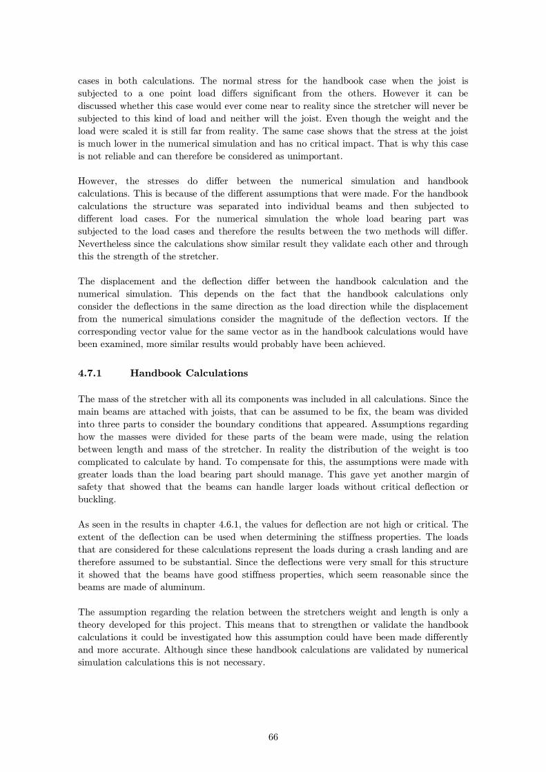
66
cases in both calculations. The normal stress for the handbook case when the joist is
subjected to a one point load differs significant from the others. However it can be
discussed whether this case would ever come near to reality since the stretcher will never be
subjected to this kind of load and neither will the joist. Even though the weight and the
load were scaled it is still far from reality. The same case shows that the stress at the joist
is much lower in the numerical simulation and has no critical impact. That is why this case
is not reliable and can therefore be considered as unimportant.
However, the stresses do differ between the numerical simulation and handbook
calculations. This is because of the different assumptions that were made. For the handbook
calculations the structure was separated into individual beams and then subjected to
different load cases. For the numerical simulation the whole load bearing part was
subjected to the load cases and therefore the results between the two methods will differ.
Nevertheless since the calculations show similar result they validate each other and through
this the strength of the stretcher.
The displacement and the deflection differ between the handbook calculation and the
numerical simulation. This depends on the fact that the handbook calculations only
consider the deflections in the same direction as the load direction while the displacement
from the numerical simulations consider the magnitude of the deflection vectors. If the
corresponding vector value for the same vector as in the handbook calculations would have
been examined, more similar results would probably have been achieved.
Handbook Calculations 4.7.1
The mass of the stretcher with all its components was included in all calculations. Since the
main beams are attached with joists, that can be assumed to be fix, the beam was divided
into three parts to consider the boundary conditions that appeared. Assumptions regarding
how the masses were divided for these parts of the beam were made, using the relation
between length and mass of the stretcher. In reality the distribution of the weight is too
complicated to calculate by hand. To compensate for this, the assumptions were made with
greater loads than the load bearing part should manage. This gave yet another margin of
safety that showed that the beams can handle larger loads without critical deflection or
buckling.
As seen in the results in chapter 4.6.1, the values for deflection are not high or critical. The
extent of the deflection can be used when determining the stiffness properties. The loads
that are considered for these calculations represent the loads during a crash landing and are
therefore assumed to be substantial. Since the deflections were very small for this structure
it showed that the beams have good stiffness properties, which seem reasonable since the
beams are made of aluminum.
The assumption regarding the relation between the stretchers weight and length is only a
theory developed for this project. This means that to strengthen or validate the handbook
calculations it could be investigated how this assumption could have been made differently
and more accurate. Although since these handbook calculations are validated by numerical
simulation calculations this is not necessary.
67
Buckling
Only attachment 1 was taken into consideration as mentioned previously. Because of the
deflection results that show that the difference between attachment 1 and 2 are negligible
and if the stretcher can handle the loads for attachment 1, it would undoubtedly handle the
loads for attachment 2 as well. It was therefore no idea to calculate buckling for attachment
2.
The values in the results according to linear beam theory are far below the critical values,
which show that there is no risk of buckling rather that the forces could be much larger
without any significant impact. The calculations from Eurocode 9 shows similar results,
which also indicates that all the beams are safe from buckling and they are also far below
the critical values. These results are perfectly reasonable considering the forces acting on
the stretcher.
The two methods differ in quite a few ways but they are both based on the same principle.
This principle compensates for the fact that predictions based on the analytical critical load
according Euler's buckling cases are non-conservative. Both methods therefore treat
buckling analysis from a more practical perspective and also the material, aluminum, is
taken into account. However the main differences are the various factors used for the
calculations. In the buckling check according to Eurocode 9 many different factors were
taken into account, for example factors for welding and imperfection. This is what makes
the method more precise and accurate. Linear beam theory on the other hand looks at
practical calculations as well but does not use as many safety factors. However it uses a
table to find the tension and since this is the maximum tension allowed before buckling it
can be used to calculate the critical load. It is therefore difficult to know which type of
factors that are included in the table and if they can represent those that are used in
Eurocode 9.
Numerical Simulation 4.7.2
The results from the simulation show values in all cases as the stress of the main part of
the model barely gets higher than 100MPa. It could therefore be established that the
structure does not present significant yielding. However, as the results show, it appeared a
few stress concentrations at certain points. These can be neglected in the stress calculations
since a static strength analysis is performed. Local plastic deformation will take place in
these areas and the stress will redistribute. This does not impact the static strength but
these stress concentrations can be misleading in the results, it is therefore important to
analyse and discuss why they emerge.
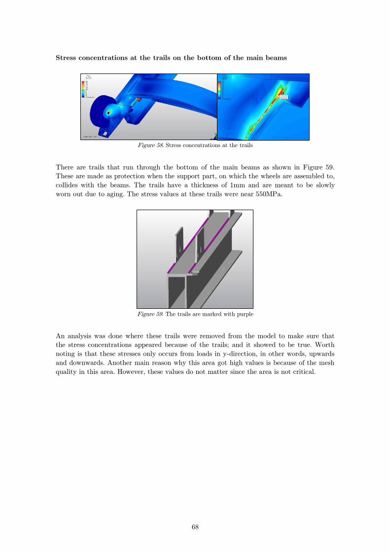
68
Stress concentrations at the trails on the bottom of the main beams
Figure 58. Stress concentrations at the trails
There are trails that run through the bottom of the main beams as shown in Figure 59.
These are made as protection when the support part, on which the wheels are assembled to,
collides with the beams. The trails have a thickness of 1mm and are meant to be slowly
worn out due to aging. The stress values at these trails were near 550MPa.
Figure 59. The trails are marked with purple
An analysis was done where these trails were removed from the model to make sure that
the stress concentrations appeared because of the trails; and it showed to be true. Worth
noting is that these stresses only occurs from loads in y-direction, in other words, upwards
and downwards. Another main reason why this area got high values is because of the mesh
quality in this area. However, these values do not matter since the area is not critical.

69
Stress concentrations around the holes at the wheels
Figure 60. Stress concentration around the holes
These areas showed to be critical for loads in all directions. In Figure 60, the picture to the
right is the stress plot from the 8g load which shows very high stresses around the holes
where the wheels are attached. The main reason for this is that the boundary condition is
set at the joint that holds up the wheel, the blue stick in the right picture. As mentioned
before, this is not how it will work in reality. The wheels are attached in a different way, as
seen in Figure 61 below, this means that the stretcher will have four attachment points.
This concludes that the area around the wheels will not be subjected with as much load as
the results show. Therefore further studies together with fixation system is needed.
Figure 61. This is how it looks like in reality. The outer attachment will be fixed in the fixation system
which does not allow the stretcher to move.
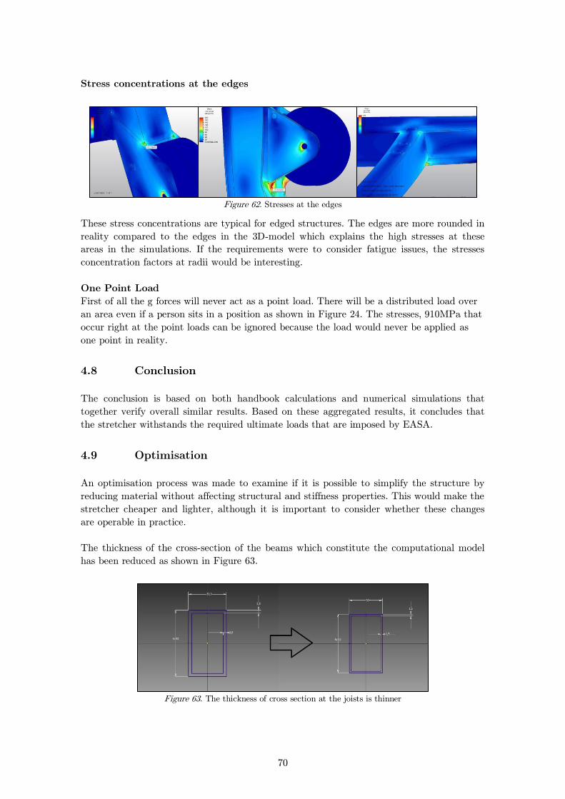
70
Stress concentrations at the edges
Figure 62. Stresses at the edges
These stress concentrations are typical for edged structures. The edges are more rounded in
reality compared to the edges in the 3D-model which explains the high stresses at these
areas in the simulations. If the requirements were to consider fatigue issues, the stresses
concentration factors at radii would be interesting.
One Point Load
First of all the g forces will never act as a point load. There will be a distributed load over
an area even if a person sits in a position as shown in Figure 24. The stresses, 910MPa that
occur right at the point loads can be ignored because the load would never be applied as
one point in reality.
4.8 Conclusion
The conclusion is based on both handbook calculations and numerical simulations that
together verify overall similar results. Based on these aggregated results, it concludes that
the stretcher withstands the required ultimate loads that are imposed by EASA.
4.9 Optimisation
An optimisation process was made to examine if it is possible to simplify the structure by
reducing material without affecting structural and stiffness properties. This would make the
stretcher cheaper and lighter, although it is important to consider whether these changes
are operable in practice.
The thickness of the cross-section of the beams which constitute the computational model
has been reduced as shown in Figure 63.
Figure 63. The thickness of cross section at the joists is thinner

71
Another detail that was easy to reduce at the same time was the pedal in the support part
to see if it was necessary to have such a big pedal as before. The comparisons of the pedals
are seen in Figure 64.
Figure 64. The pedal to the right is narrower
The old pedal had a volume of 368706mm3 and the new one have a volume of 102201mm3.
The new mass of the model is 5.85kg which is a material reduction by 22%.
Displacement and Stress due to Load Case 1
Figure 65. Displacement plot
Maximum displacement: 8mm at the pedal, see Figure 65.
The displacement at the main beams is approximately 2.6mm. The beams were bent similar
to the original while the pedal was bent much more now when it is smaller.
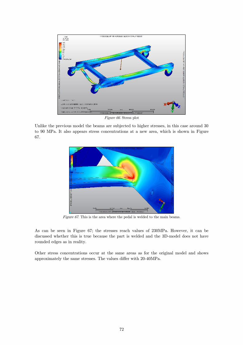
72
Figure 66. Stress plot
Unlike the previous model the beams are subjected to higher stresses, in this case around 30
to 90 MPa. It also appears stress concentrations at a new area, which is shown in Figure
67.
Figure 67. This is the area where the pedal is welded to the main beams.
As can be seen in Figure 67; the stresses reach values of 230MPa. However, it can be
discussed whether this is true because the part is welded and the 3D-model does not have
rounded edges as in reality.
Other stress concentrations occur at the same areas as for the original model and shows
approximately the same stresses. The values differ with 20-40MPa.

73
Displacement and Stress due to Load Case 2
Figure 68. Displacement plot
Maximum displacement: 4.98mm at the main beams - an increase with 2.74mm from the
original model.
Figure 69. Stress plot
The plot shows the same values on the beams as for the original model. The same stress
concentrations appears but with higher values. The stresses near the joints for the wheels
have values up to 987MPa, and other edges have values around 350MPa.
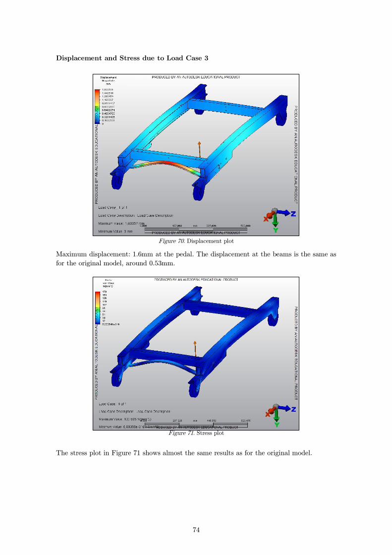
74
Displacement and Stress due to Load Case 3
Figure 70. Displacement plot
Maximum displacement: 1.6mm at the pedal. The displacement at the beams is the same as
for the original model, around 0.53mm.
Figure 71. Stress plot
The stress plot in Figure 71 shows almost the same results as for the original model.

75
Displacement and Stress due to Load Case 4
Figure 72. Displacement plot
Maximum displacement: 0.67mm at the front joist and at the pedal. The deflection has
increased with about 0.28mm from the original.
Figure 73. Stress plot
No noticeable difference from the original model was observed which indicates that there is
no major difference between the results where the stresses at the main beams are between 5
to 30MPa. The same stress concentrations occur as for the original model.

76
One Point Load due to Load Case 5
Figure 74. Displacement plot
Maximum displacement: 4.09mm at the main beams where the force is loaded; an increase
with 0.99mm from the original model.
Figure 75. Stress plot
As the plot can tell, there are very high stress values where the force is placed; almost three
times higher than the original. This is obviously because of the thickness decrease at the
beams.
Discussion
The result for the optimisation shows higher stress and displacement values than the
original model. When analysing the whole structure it would still be allowed to reduce the
materials and still get acceptable results. But there are some areas that might get critical
when they are made thinner. These areas are where the pedal is welded when applying 20g
downward and the area around the holes at the wheels when applying 8g sideward. The
77
stiffness at these areas is clearly reduced. However it may be discussed how important the
pedal is to stiffness property for the load bearing part. It is also hard to determinate if the
area around the hole would be able to stand against failure or undergo significant yielding
because in reality, the boundary values are set in a different way. But to be sure, it is not
recommended to make these areas that thin and non-linear simulations could therefore be
an interesting future approach to further study weight reduction.
However it is a question about the manufacturing restrictions and user friendliness for the
customer. When reducing the material of a product it is important to check the
manufacturing restrictions that may be a hold back for the new construction, especially
when it comes to such thin constructions. The material reduction might also give negative
effect on the user friendliness for the customer. For example, the reason for the size of the
pedal may be made because it will be easier for the staff to use the stretcher and making it
smaller might cause problems.

78
5 Fixation System
The stretcher is the tool that helps the paramedics to carry an injured person in and out
from the helicopter, it is therefore important to make it as easy as possible for the
paramedics to attach and detach it in the helicopter. The stretcher is placed preferably
where the orange parts are located in Figure 76. As the figure shows, the stretcher is
surrounded by objects in the helicopter that gives limited access to manage it. When the
stretcher is unnecessary for the helicopter operation it is desirable to use its space for cargo.
Consequently it is convenient to design the fixation system to be as low as possible to not
take up unnecessary space. This also reduces the different ways the attachment can be
designed and all the concepts in 5.4 are taking these limitations into account. In this
chapter the developing process is shown and a final concept is presented.
Figure 76. Interior of the helicopter.
5.1 Method
Several tools were used to develop the fixation system for the stretcher. First of all a
requirement specification was produced, based on that concepts for both positioning and
locking were generated through brainstorming. All concepts were compiled to a
morphological matrix and an evaluation process was made. The first step was to make an
elimination matrix to eliminate the concepts that for different reasons were not realisable.
The next step in the process was to rank the concepts. This was done by making two Pugh
matrices, which were based on the requirement. By considered the result in both matrices a
final concept was developed. To evaluate the material and manufacturing method of the
final concept a LCA was performed with several assumptions. These are presented in the
following list:
Traveling distance of 240km/day.
365 flight days/year.
The same construction of the fixation system was used for both titanium and
aluminium.
To enhance the understanding of working with the stretcher in reality and how it is used,
study visits at the ambulance helicopter base in Säve, the ambulance division at
Sahlgrenska University Hospital and the stretcher manufacturer Ferno Norden were
organised. The choice of the visits was made to get diverse input from different users. To

79
find out what the SAR crew thought about working with the Allfa Europe Premium
stretcher an interview was held.
Attachments 5.1.1
Further on, the following names are used to describe the different attachments on the
stretcher: The inner attachment and the outer attachment. See Figure 77 and Figure 78.
Figure 77. The inner attachment.
Figure 78. The outer attachment
5.2 Black Box and Function Structure
In the beginning of the development process a hypothetic black box, Figure 79, and
function structure, Figure 80, were made. The hypothetic black box and the function
structure are tools which help to develop the fixation system in an open-minded way
without the influence of existing products12. The black-box describes inputs and outputs to
the fixation system and the function structure describes more in detail the assumed steps
for the function of the fixation system.
12 Söderberg, Rikard. Produktarkitektur, lecture 2013-10-28
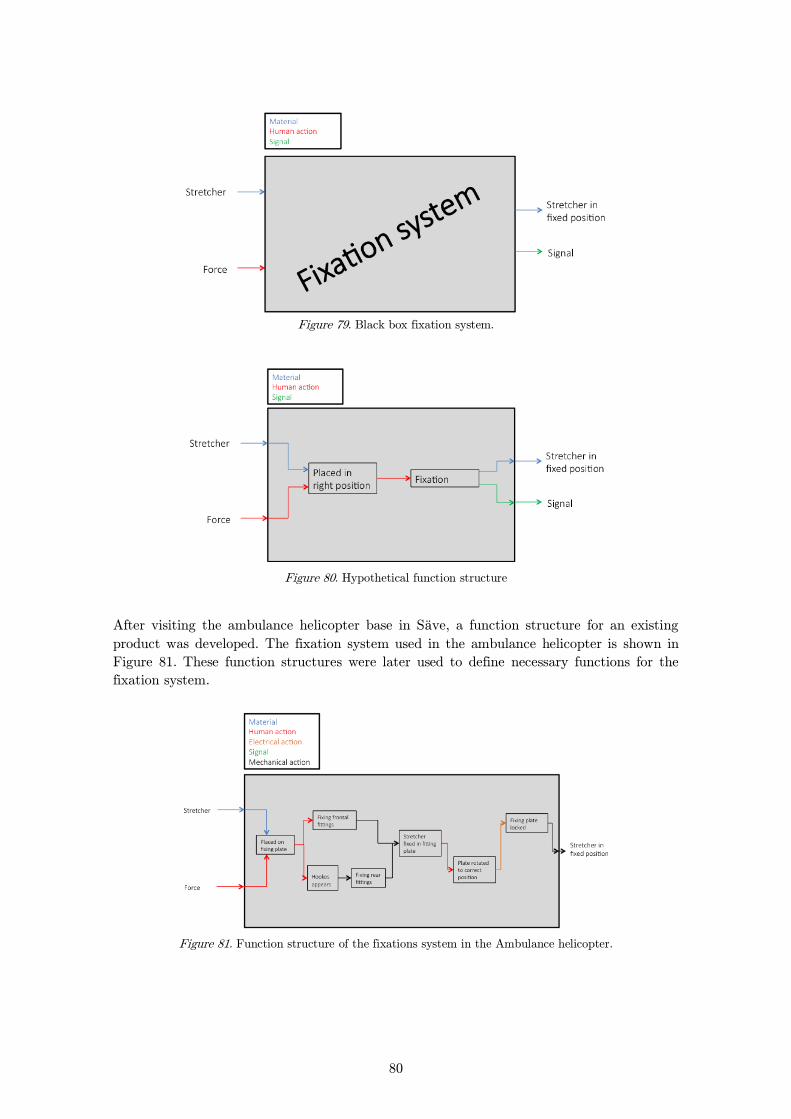
80
Figure 79. Black box fixation system.
Figure 80. Hypothetical function structure
After visiting the ambulance helicopter base in Säve, a function structure for an existing
product was developed. The fixation system used in the ambulance helicopter is shown in
Figure 81. These function structures were later used to define necessary functions for the
fixation system.
Figure 81. Function structure of the fixations system in the Ambulance helicopter.

81
5.3 Requirement Specification
The specification contains requirements and requests that define the groundings for the
product. To define these, requirements from EASA, CS 29, and information from Heli-one,
paramedics and helicopter crew from Gothenburg were considered and the requests were
graded based on significance on a scale from 1 to 5, where 5 is the most significant. A
description on the control method for the requests and requirements was also presented.
The result can be seen in the Table 21.
Table 21. The table shows the requirements and the requests that the fixations system must have.
Requirement Specification
Requirement/request Control method Value Requirement/Request Weight
EASA
Comply with certification
requirement (EASA CS
29)
Calculation, test - Requirement -
Size
Weight Calculation 40 kg Requirement -
Weight Calculation 20 kg Request 4
Time between service Calculation, test 1 year Requirement -
Maximum height Calculation 200mm Requirement -
Time
Installation time for
stretcher Evaluation 15s Requirement -
Installation time for
stretcher Evaluation 5s Request 2
Demount of stretcher Evaluation 20s Requirement -
Demount of stretcher Evaluation 7s Request 2
Service life Calculation, test 10 years Requirement -
Environment
Ability to separate
materials at disposal Evaluation 95% Request 1
Number of components Calculation 20 Request 2
Maximum number of
different materials Calculation 5 Request 1
Features
Possibility to strap cargo Evaluation - Requirement -
Possibility to place the
stretcher in two directions Evaluation - Requirement -
Possibility to place the
stretcher in two locations Evaluation - Requirement -
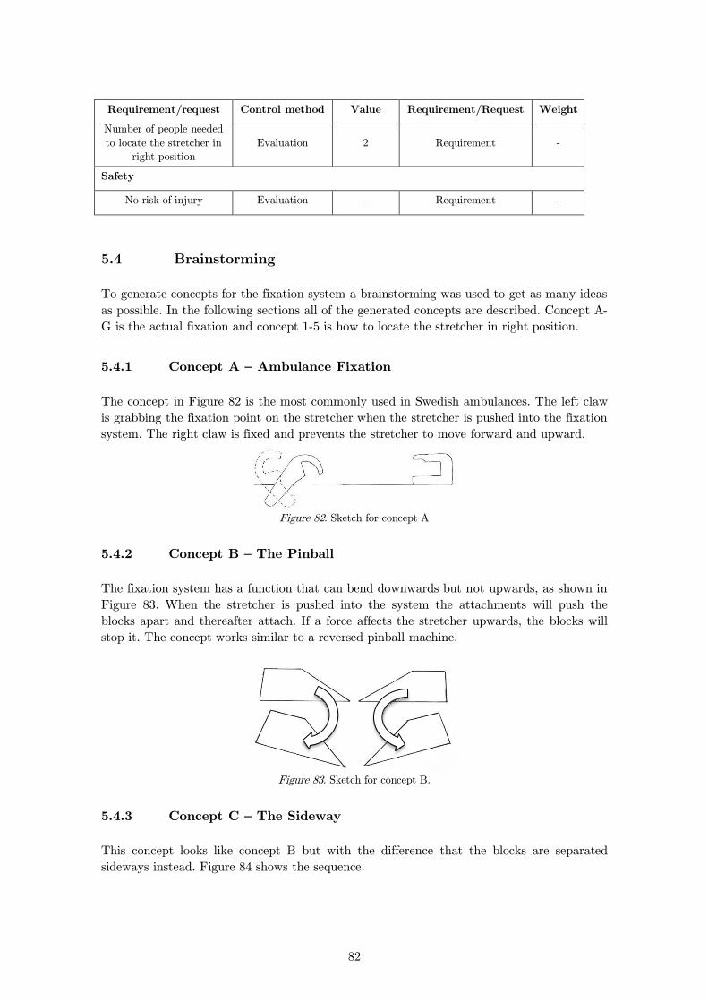
82
Requirement/request Control method Value Requirement/Request Weight
Number of people needed
to locate the stretcher in
right position
Evaluation 2 Requirement -
Safety
No risk of injury Evaluation - Requirement -
5.4 Brainstorming
To generate concepts for the fixation system a brainstorming was used to get as many ideas
as possible. In the following sections all of the generated concepts are described. Concept A-
G is the actual fixation and concept 1-5 is how to locate the stretcher in right position.
Concept A – Ambulance Fixation 5.4.1
The concept in Figure 82 is the most commonly used in Swedish ambulances. The left claw
is grabbing the fixation point on the stretcher when the stretcher is pushed into the fixation
system. The right claw is fixed and prevents the stretcher to move forward and upward.
Figure 82. Sketch for concept A
Concept B – The Pinball 5.4.2
The fixation system has a function that can bend downwards but not upwards, as shown in
Figure 83. When the stretcher is pushed into the system the attachments will push the
blocks apart and thereafter attach. If a force affects the stretcher upwards, the blocks will
stop it. The concept works similar to a reversed pinball machine.
Figure 83. Sketch for concept B.
Concept C – The Sideway 5.4.3
This concept looks like concept B but with the difference that the blocks are separated
sideways instead. Figure 84 shows the sequence.
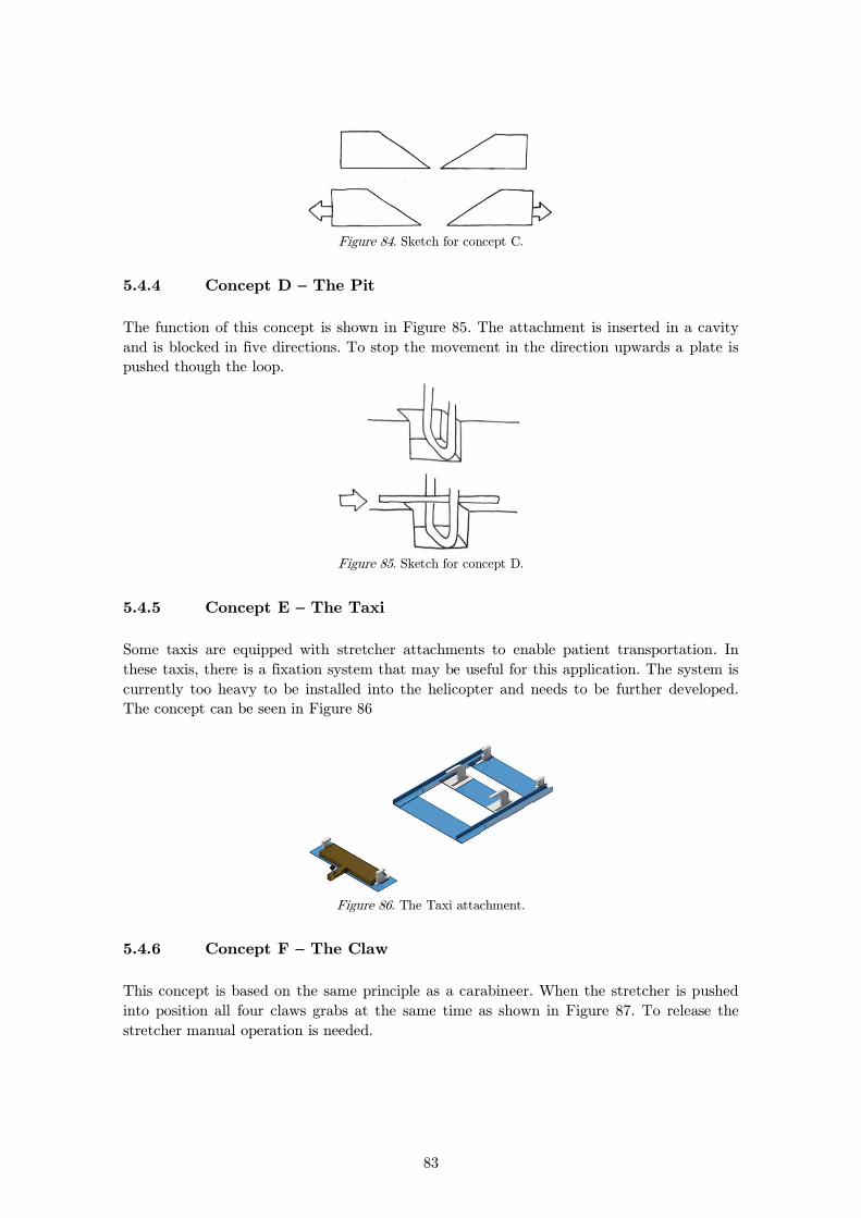
83
Figure 84. Sketch for concept C.
Concept D – The Pit 5.4.4
The function of this concept is shown in Figure 85. The attachment is inserted in a cavity
and is blocked in five directions. To stop the movement in the direction upwards a plate is
pushed though the loop.
Figure 85. Sketch for concept D.
Concept E – The Taxi 5.4.5
Some taxis are equipped with stretcher attachments to enable patient transportation. In
these taxis, there is a fixation system that may be useful for this application. The system is
currently too heavy to be installed into the helicopter and needs to be further developed.
The concept can be seen in Figure 86
Figure 86. The Taxi attachment.
Concept F – The Claw 5.4.6
This concept is based on the same principle as a carabineer. When the stretcher is pushed
into position all four claws grabs at the same time as shown in Figure 87. To release the
stretcher manual operation is needed.

84
Figure 87. Sketch for concept F.
Concept G – Helicopter Fixation 5.4.7
The fixation system in one of the ambulance helicopters at Säve has the following functions.
The first fixation, see Figure 88, is similar to concept F with the same principle as a
carabineer. The second fixation is the same as in concept A and E, with the exception that
it can be pushed down under the floor to make room for the rest of the stretcher. See
Figure 89.
Figure 88. The stretcher attached to the fixation system.
Figure 89. Concept for fixation system
Concept 1 – The Lift 5.4.8
The position of the stretcher makes it difficult for the paramedics to roll or drag it on the
floor in the helicopter. The blue container, see Figure 76, is blocking the path from entrance
or exit to the stretcher’s attachment position. The container is surrounded by high edges
and consequently the stretcher must be lifted over the edges and thereafter be lowered
down into the fixation system vertically, see Figure 90.
Figure 90. Sketch for concept 1.
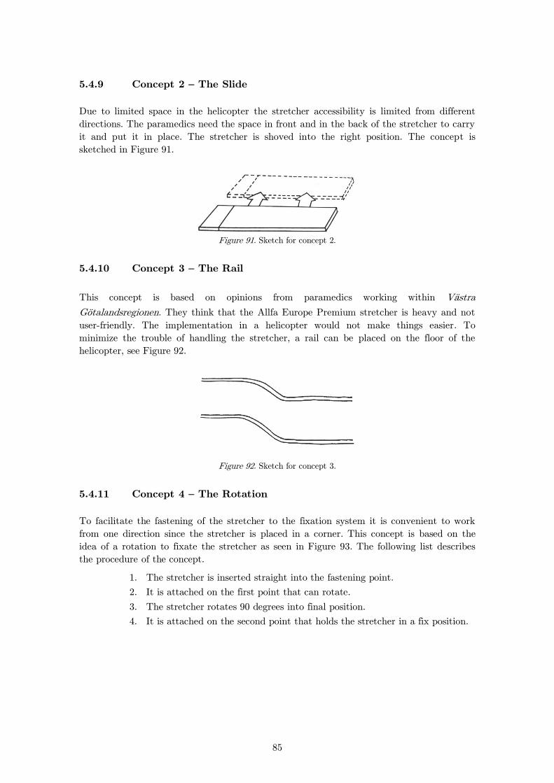
85
Concept 2 – The Slide 5.4.9
Due to limited space in the helicopter the stretcher accessibility is limited from different
directions. The paramedics need the space in front and in the back of the stretcher to carry
it and put it in place. The stretcher is shoved into the right position. The concept is
sketched in Figure 91.
Figure 91. Sketch for concept 2.
Concept 3 – The Rail 5.4.10
This concept is based on opinions from paramedics working within Västra
Götalandsregionen. They think that the Allfa Europe Premium stretcher is heavy and not
user-friendly. The implementation in a helicopter would not make things easier. To
minimize the trouble of handling the stretcher, a rail can be placed on the floor of the
helicopter, see Figure 92.
Figure 92. Sketch for concept 3.
Concept 4 – The Rotation 5.4.11
To facilitate the fastening of the stretcher to the fixation system it is convenient to work
from one direction since the stretcher is placed in a corner. This concept is based on the
idea of a rotation to fixate the stretcher as seen in Figure 93. The following list describes
the procedure of the concept.
1. The stretcher is inserted straight into the fastening point.
2. It is attached on the first point that can rotate.
3. The stretcher rotates 90 degrees into final position.
4. It is attached on the second point that holds the stretcher in a fix position.

86
Figure 93. Sketch
5.5 Matrices
Morphological Matrix
A morphological matrix is a commonly used tool to illustrate how to combine the different
sub concepts into full concepts13. In Table 22 all the earlier described concepts are
presented in a morphological matrix. How these concepts can be combined is shown in
Appendix F, where “x” means that the concepts can be combined.
Table 22. Morphological Matrix.
Elimination Matrix
The elimination matrix is used to eliminate unrealisable concepts, or those concepts that
clearly would not meet all requirements.14 The first step in the elimination process was to
use an Elimination matrix, which can be found in Appendix F. The reasons why some
concepts were eliminated are presented in “Comments”. After the elimination, 8 concepts
were remaining.
13 Lindstedt, Per and Burenius, Jan ; The Value Model, 2003. 14 Lindstedt, Per and Burenius, Jan ; The Value Model, 2003.
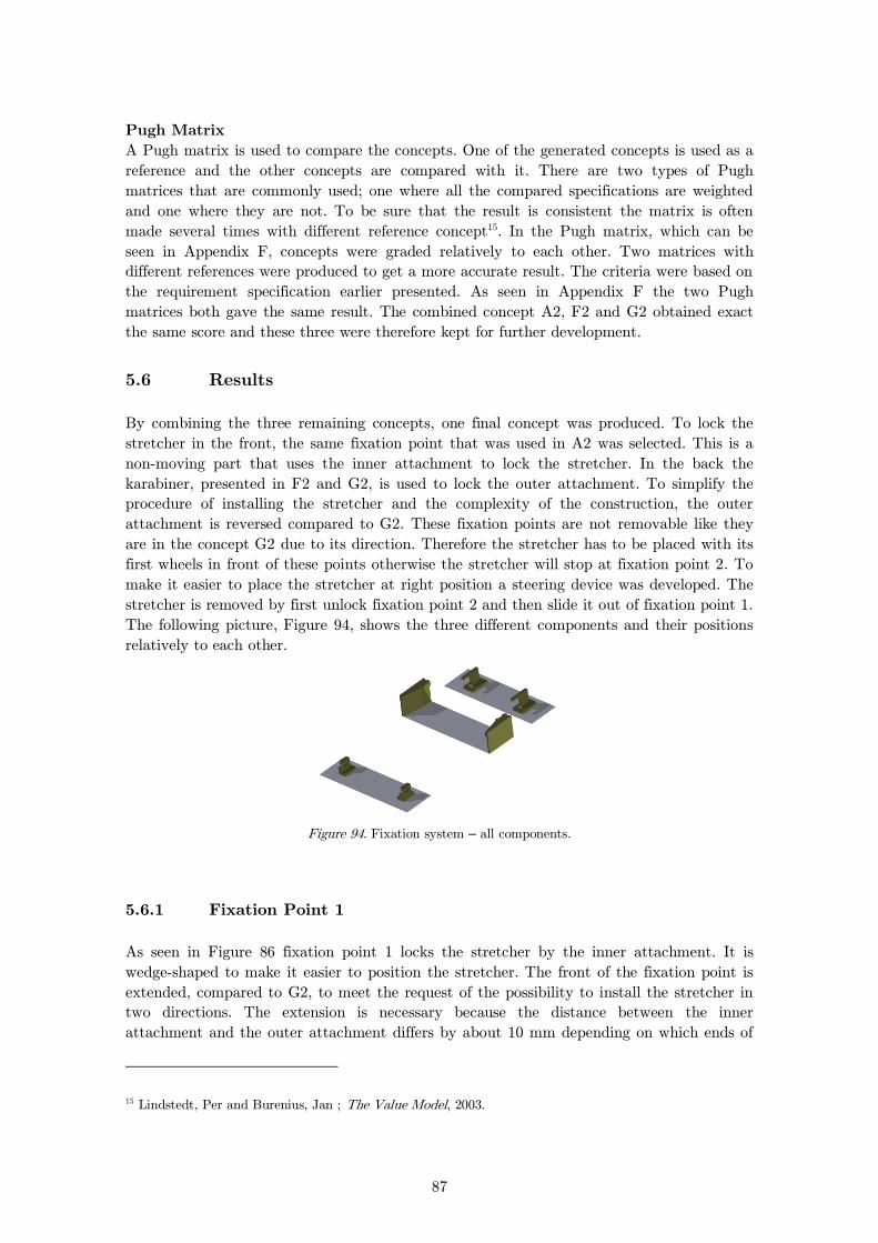
87
Pugh Matrix
A Pugh matrix is used to compare the concepts. One of the generated concepts is used as a
reference and the other concepts are compared with it. There are two types of Pugh
matrices that are commonly used; one where all the compared specifications are weighted
and one where they are not. To be sure that the result is consistent the matrix is often
made several times with different reference concept15. In the Pugh matrix, which can be
seen in Appendix F, concepts were graded relatively to each other. Two matrices with
different references were produced to get a more accurate result. The criteria were based on
the requirement specification earlier presented. As seen in Appendix F the two Pugh
matrices both gave the same result. The combined concept A2, F2 and G2 obtained exact
the same score and these three were therefore kept for further development.
5.6 Results
By combining the three remaining concepts, one final concept was produced. To lock the
stretcher in the front, the same fixation point that was used in A2 was selected. This is a
non-moving part that uses the inner attachment to lock the stretcher. In the back the
karabiner, presented in F2 and G2, is used to lock the outer attachment. To simplify the
procedure of installing the stretcher and the complexity of the construction, the outer
attachment is reversed compared to G2. These fixation points are not removable like they
are in the concept G2 due to its direction. Therefore the stretcher has to be placed with its
first wheels in front of these points otherwise the stretcher will stop at fixation point 2. To
make it easier to place the stretcher at right position a steering device was developed. The
stretcher is removed by first unlock fixation point 2 and then slide it out of fixation point 1.
The following picture, Figure 94, shows the three different components and their positions
relatively to each other.
Figure 94. Fixation system – all components.
Fixation Point 1 5.6.1
As seen in Figure 86 fixation point 1 locks the stretcher by the inner attachment. It is
wedge-shaped to make it easier to position the stretcher. The front of the fixation point is
extended, compared to G2, to meet the request of the possibility to install the stretcher in
two directions. The extension is necessary because the distance between the inner
attachment and the outer attachment differs by about 10 mm depending on which ends of
15 Lindstedt, Per and Burenius, Jan ; The Value Model, 2003.
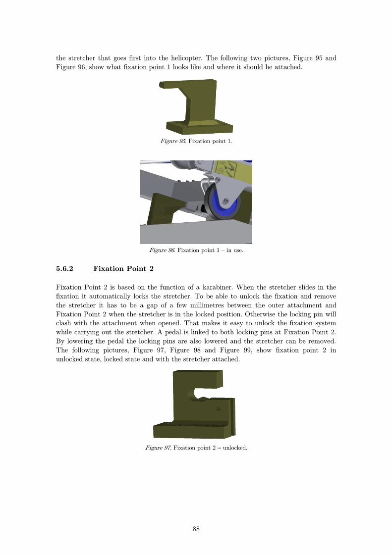
88
the stretcher that goes first into the helicopter. The following two pictures, Figure 95 and
Figure 96, show what fixation point 1 looks like and where it should be attached.
Figure 95. Fixation point 1.
Figure 96. Fixation point 1 – in use.
Fixation Point 2 5.6.2
Fixation Point 2 is based on the function of a karabiner. When the stretcher slides in the
fixation it automatically locks the stretcher. To be able to unlock the fixation and remove
the stretcher it has to be a gap of a few millimetres between the outer attachment and
Fixation Point 2 when the stretcher is in the locked position. Otherwise the locking pin will
clash with the attachment when opened. That makes it easy to unlock the fixation system
while carrying out the stretcher. A pedal is linked to both locking pins at Fixation Point 2.
By lowering the pedal the locking pins are also lowered and the stretcher can be removed.
The following pictures, Figure 97, Figure 98 and Figure 99, show fixation point 2 in
unlocked state, locked state and with the stretcher attached.
Figure 97. Fixation point 2 – unlocked.
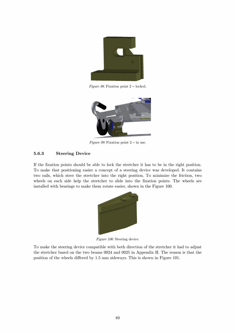
89
Figure 98. Fixation point 2 – locked.
Figure 99. Fixation point 2 – in use.
Steering Device 5.6.3
If the fixation points should be able to lock the stretcher it has to be in the right position.
To make that positioning easier a concept of a steering device was developed. It contains
two rails, which steer the stretcher into the right position. To minimize the friction, two
wheels on each side help the stretcher to slide into the fixation points. The wheels are
installed with bearings to make them rotate easier, shown in the Figure 100.
Figure 100. Steering device.
To make the steering device compatible with both direction of the stretcher it had to adjust
the stretcher based on the two beams 0024 and 0025 in Appendix H. The reason is that the
position of the wheels differed by 1.5 mm sideways. This is shown in Figure 101.
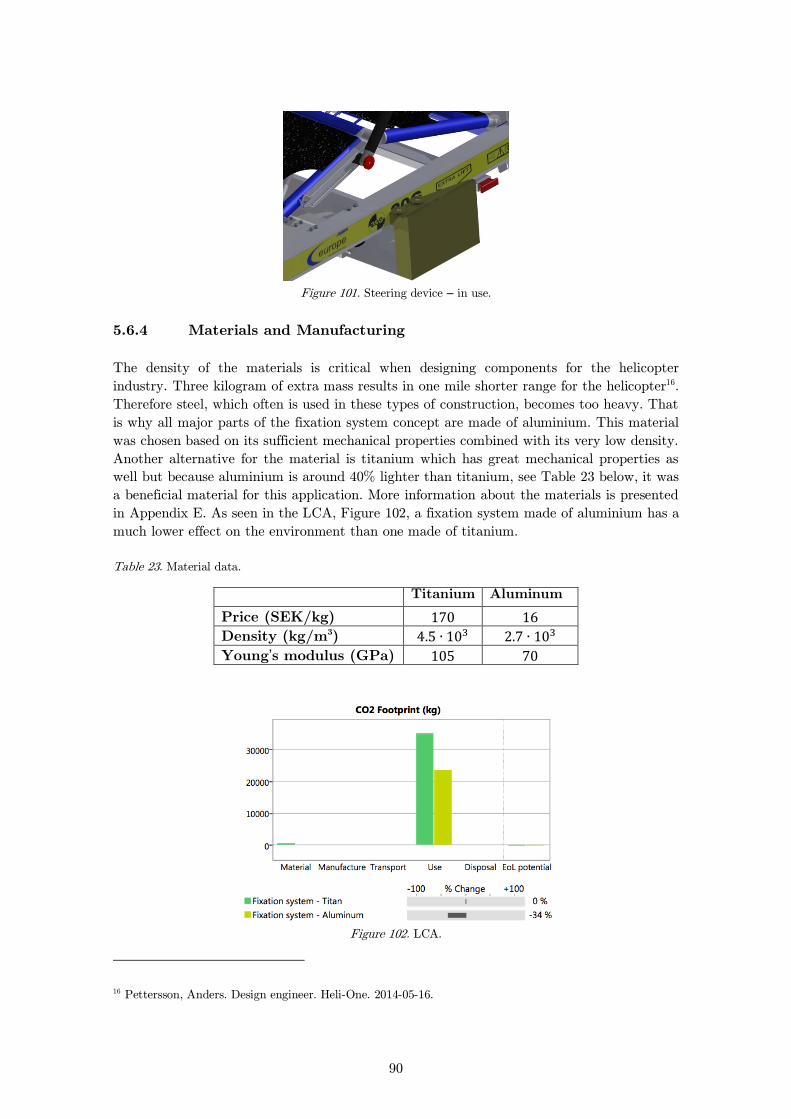
90
Figure 101. Steering device – in use.
Materials and Manufacturing 5.6.4
The density of the materials is critical when designing components for the helicopter
industry. Three kilogram of extra mass results in one mile shorter range for the helicopter16.
Therefore steel, which often is used in these types of construction, becomes too heavy. That
is why all major parts of the fixation system concept are made of aluminium. This material
was chosen based on its sufficient mechanical properties combined with its very low density.
Another alternative for the material is titanium which has great mechanical properties as
well but because aluminium is around 40% lighter than titanium, see Table 23 below, it was
a beneficial material for this application. More information about the materials is presented
in Appendix E. As seen in the LCA, Figure 102, a fixation system made of aluminium has a
much lower effect on the environment than one made of titanium.
Table 23. Material data.
Titanium Aluminum
Price (SEK/kg)
Density (kg/m3)
Young’s modulus (GPa)
Figure 102. LCA.
16 Pettersson, Anders. Design engineer. Heli-One. 2014-05-16.
91
Achieved Requirement Specification. 5.6.5
As seen in Table 24 most of the requests and requirements are met but a few have to be
further investigated. Green means met and grey means further investigation needed.
Table 24. Achieved Requirement specification.
Achieved Requirement Specification
Requirement/request Requested
value Met/Not
met Comment
Real value
EASA
Comply with certification requirement (EASA
CS.29) - ? See chapter 5.7
Size
Weight 40 kg
According to 3D-model 12kg
Weight 20 kg
According to 3D-model 12kg
Time between service 1 year ? See chapter 5.7
Maximum height 200mm
According to 3D-model 140mm
Time
Installation time for stretcher
15s
Estimated value ˂5s
Installation time for stretcher
5s
Estimated value ˂5s
Demount of stretcher 20s
Estimated value ˂7s
Demount of stretcher 7s
Estimated value ˂7s
Service life 10 years ? See chapter 5.7
Enviroment
Ability to separate materials at disposal
95%
Estimated value according to 3D-model ˃95%
Number of components 20
According to 3D-model 20
Maximum number of different materials
5
According to 3D-model 4
Features
Possibility to strap cargo - ? See chapter 5.7
Possibility to place the stretcher in two directions
-
According to 3D-model
Possibility to place the stretcher in two locations
in the helicopter -
According to 3D-model
92
Requirement/request Requested
value Met/Not
met Comment
Real value
Number of people needed to locate the stretcher in
right position 2
Estimated value
according to 3D-model 2
Safety
No risk of injury -
No risk detected
5.7 Discussion
In the development of the fixation system the concepts were eliminated despite inadequate
information depending on lack of resources. With more resources it would have been
appropriate to perform deeper analyses of the concepts in form of calculations and
prototypes and a better and more complete concept could have been developed.
To minimize the error in the LCA, the same distance was used for both titanium and
aluminium. If the traveling distance would change, a different result would be achieved but
the relationship between the two materials would be intact. However it might be possible
to, as described earlier, minimize the reinforcements when choosing titanium. In that case
titanium probably would perform better in the LCA.
The manufacturing cost was not considered when the ideas of a fixation system were
developed. This decision was based on the normally large cost for certification of equipment
placed in a helicopter. Thereby the manufacturing cost is a minor cost in the project.
5.8 Further Development
Because of time limitation some analysis could not be performed. The following sections
present a recommended further development process and a discussion of used methods.
Next step in the development process is to determine the optimal shape of the components
as well as the exact function of the unlocking pedal. All requirements from EASA have to
be considered to get the fixation system certified for use in helicopters. To do so a strength
analysis among other things has to be done. An idea that has not been further investigated
is to cover the outside of fixation point 1 with rubber to minimize the wear of both the
stretcher and the fixation point. It might also help the stretcher to be in place without
cause unwanted vibrations. An analysis of service life and time between services has to be
done to see if the fixation system meets the requests and requirements earlier presented in
the requirement specification.
Since it is of high importance due to lack of space in SAR helicopters, the possibility to
strap cargo onto the fixation system needs to be examined more. One way to make that
possible is to make holes in the fixation points. How that would affect the mechanical
properties of the construction needs to be analysed.
93
The final material and manufacturing process also needs to be determined. By using
titanium instead of aluminium the reinforcements of the fixation points could be minimized
and thereby save weight. Titanium has a disadvantage compared to aluminium though; it is
much more expensive, as seen in Table 23. According to all analyses that were made
aluminium is a better choice than titanium but to be completely sure, further investigation
is recommended.
To minimize the risk of problem when the fixation system is in use, feedback from the users
is crucial to get knowledge about the problems as early as possible.
94
6 Discussion
After the visit at Heli-One in Stavanger, Norway, it turned out that the project was
different and larger than expected, for example the importance of EASA requirements was
not considered before the visit. In order to organise the project a project plan, see Appendix
G, was made. Even though the project became wider, the project plan turned out to be
reasonable because most of the tasks were done in right order and according to the time
frame that was set for each task. Furthermore some additional tools were presented by
Heli-One several weeks after set up of the project, for example Eurocode, caused some
adjustments to the project plan. These tools were given as a help to deepen the study and
make it more accurate but at the same time it also increased the workload. Furthermore
some of the parts could have been more overlapped, for example the EASA study could
have started earlier to gain greater understanding of the regulations before the strength
analysis started, this to support the calculations with necessary information.
The project was divided into four parts since these differed considerable from each other.
This allowed for the examination of each part to be more profound. This also applies to the
report and its disposition since it was divided as well but they were still supposed to be
linked together. Therefore it is important to reflect on how the different parts depend on
each other’s requirements and results. This implies that an error in one of the sections
would affect the result in all the others and thereby alter the result of the whole project.
The error in measurements that occurred in the creating of the 3D-model could cause
deviations between the results from the strength analysis and the real strength properties of
the stretcher. Even the error from the adjustment in the assembly could cause deviation in
the strength analysis. However this should not be a problem because the load bearing
structure and the critical parts were measured more precise than the rest of the parts. This
also means that the design of the 3D-model will differ from the reality. With respect to
limited computer power some simplifications of the structure in the 3D-model had to be
done. This could be the reason why such high stresses occur in some parts. It could also
depend on the difficulties with mesh refinement caused by limitations in the software. The
high stresses caused uncertainties when verifying the stretcher according to EASA but after
discussions with the supervisors the conclusion was that these stresses would not occur in
reality. In order to obtain a more reliable stress distribution from the numerical simulations
a more accurate modelling and meshing would be required, such as definition of radii and
contact conditions.
All the assumptions in the strength analysis section are based on knowledge from three
years studying mechanical engineering. These assumptions were discussed with supervisors
and Heli-One, although it is important to reflect how these assumptions would differ made
by another perpetrator.
The paragraphs in EASA are very clear about the material specifications and the
fabrication methods. It was very hard to find approved specifications but different sources
have been compared and they showed similar properties. Therefore this should not affect
the results of the calculations but the material specification is still not reliable enough to
use in a certification. In the validation for certification an assumption was made that the
stretcher would be installed within 15° of the longitudinal axis of the rotorcraft, see Table

95
1. This depends on the installation of the fixation system. If the system is slanted installed
the stretcher will also be slanted and this paragraph in EASA needs to be reconsidered. The
material and fabrication method of the fixation system will affect the verification; especially
if casting is chosen as fabrication method, which it probably will be.
6.1 Reflection of Method
A requirement was that the software Autodesk Mechanical Simulations had to be used.
This might have contributed to that various features that had been good to use in this case
not were considered. If software for example ANSYS, which is a preselected program at
Chalmers University of Technology, had been used some of these problems could have been
eliminated. The computer did not have enough performance to run complex simulations
with too many equations due to a high number of elements. An example was that the
computer could not handle an increased number of elements with a further 30% from the
last mesh level in the mesh analysis. Consequently this resulted in a delay in the project
plan. Better computer capacity would have been desirable for the 3D-modelling as well
because some dynamic functions were hard to demonstrate with the computers provided by
the university.
The usage of reverse engineering and conventional was a good choice for both 3D-modelling
and in the development of the fixation system. This is because they are well established
methods both among companies and for education. For example the division of Product and
Production development advocates reverse engineering for these kinds of projects. Therefore
these methods could be considered as trustworthy. The usages of matrices, Pugh,
Morphological and elimination, which can be found in Appendix F are not completely
unprejudiced. Even if these kinds of matrices are great tools, they are still not entirely
reliable. This depends on lack of information and resources for building prototypes for each
concept.
The two theoretical methods used in the strength analysis for buckling are both well
established. Grundläggande hållfasthetslära is used as course literature at many of the
courses in solid mechanics at Chalmers University of Technology. Eurocode is produced by
European Committee for Standardisation and is thereby a reliable working method.

96
7 Conclusion
As mentioned in chapter 1.2 the aim of this project was to produce a fully dynamic 3D-
model and investigate whether the stretcher meets the requirements to be used in large
rotorcrafts. A 3D-model was made to virtually demonstrate all the functions of the
stretcher. Parts of the model were also used in finite element simulations. The strength
analysis was made in accordance with EASA regulations and show that the stretcher would
withstand required loads in CS 29.561b. To ensure the credibility of the strength analysis
both handbook calculations and numerical simulations were performed. The stress results
show good agreement with each other based on the fact that the results from the handbook
calculations are of the same scale of magnitude as the results from the numerical
simulations. The two buckling checks show similar results, which indicate that the theses
results are reliable as well. The strength analysis did only consider the load bearing part
and not the seat of the stretcher or fixation system and the interface between the helicopter
and the fixation system. The project only resulted in a concept for the fixation system.
The project was successful in developing the 3D-model with all dynamic functions. A
preliminary study of the requirements in EASA gives indication of the fact that the
stretcher would fulfil certification requirements. All paragraphs that could not be fulfilled
with simple calculations or tests were discussed with a compliance verification engineer at
Heli-One until a conclusion was reached and therefore the results of the verification are
considered reliable.

97
8 Recommendations
The results from the strength analysis and the discussed paragraphs indicate that the
stretcher would be properly installed in the helicopter, but to be able to certify the
stretcher the following list of tasks is recommended.
Investigate the strength of the fixation system.
Determine the optimal shape, material and fabrication method of the fixation system.
Make calculations or suitable test on the seat of the stretcher to make sure that it
will not come loose during a flight or in a crash.
Find an approved material specification.
Control the welded parts to ensure the strength.
Fatigue analysis for stretcher and fixation system.
Examine if drain holes are necessary and in that case analyse the strength of the new
structure.
Analyse the suitability of the belts and harnesses used on the stretcher, both with
respect to strength and with respect to CS 29.785c which states that seat belts and
harnesses should be connected with a single point release. The visit at S ve’s
ambulance helicopter showed they use an older version of the Allfa Europe but the
belts and harness was replaced with a restraining system from the company Schroth
racing17, see Figure 103, who usually makes harnesses and other restraining systems
to racing cars.
Figure 103. Seat belt and shoulder harness with single point release.
The stretcher has some optimisation potential, both in the design and in the
manufacturing. The recommendations are listed below.
Reduce the thicknesses of the main beams as mentioned in chapter 4.9. These
reductions have to be controlled with respect to eventually manufacturing problems
and user friendliness.
17 Schroth Safety Products (1946)
98
Investigate how other cross sections will withstand the required loads and how much
weight that could be eliminated.
Use more standardised components in especially the screws and nuts.

99
Bibliography
British Standards Institution, Eurocode 9: Design of aluminium structure – Del 1-1:
General rules – General rules and rules for building (DD ENV 1999-1-1:2000), BSi, 2000,
ICS 91.010.30; 91.080.10
European Aviation Safety Agency, Certification Specifications for Large Rotorcraft: CS-29.
Amendment 3. European Aviation Safety Agency, 2012
Kaisarlis George J., A Systematic Approach for Geometrical and Dimensional Tolerancing
in Reverse Engineering, Reverse Engineering - Recent Advances and Applications, Dr. A.C.
Telea (Ed.), ISBN: 978-953- 51-0158-1, InTech, Available from:
http://www.intechopen.com/books/reverse-engineering-recent-advances- and-
applications/a-systematic-approach-for-geometrical-and-dimensional-tolerancing-in-reverse-
engineering, 2012, (2014-05-07)
Lindstedt, Per and Burenius, Jan; The Value Model, Kullavik: Nimba AB, 2003.
Lundh Hans, Grundläggande hållfasthetslära. Ed. 2. Institutionen för hållfasthetslära, KTH
Stockholm, 2000
Schroth Saftey Products, Restraint systems, http://english.schroth.com/, (2014-05-14)
Sundström Bengt, Handbok och formelsamling i Hållfasthetslära. Ed. 1. Institutionen för
hållfasthetslära, KTH Stockholm, 1998
Söderberg, Rikard; Professor at the division of Product and Production Development,
Chalmers University of Technology. Produktarkitektur, lecture 2013-10-28

I
Appendix A
The figures below show the stretcher in different angles and in different positions.

II

III
Appendix B
EASA Certification Specification 29
Subpart C – Strength Requirement
GENERAL
CS 29.301 Loads
(a) Strength requirements are specified in
terms of limit loads (the maximum loads to be
expected in service) and ultimate loads (limit
loads multiplied by prescribed factors of safety).
Unless otherwise provided, prescribed loads are
limit loads.
(b) Unless otherwise provided, the specified
air, ground, and water loads must be placed in
equilibrium with inertia forces, considering each
item of mass in the rotorcraft. These loads must
be distributed to closely approximate or
conservatively represent actual conditions.
(c) If deflections under load would
significantly change the distribution of external or
internal loads, this redistribution must be taken
into account.
CS 29.303 Factor of safety
Unless otherwise provided, a factor of safety of
1.5 must be used. This factor applies to external
and inertia loads unless its application to the
resulting internal stresses is more conservative.
CS 29.305 Strength and deformation
(a) The structure must be able to support
limit loads without detrimental or permanent
deformation. At any load up to limit loads, the
deformation may not interfere with safe operation.
(b) The structure must be able to support
ultimate loads without failure. This must be
shown by:
(1) Applying ultimate loads to the
structure in a static test for at least 3 seconds; or
(2) Dynamic tests simulating actual
load application.
CS 29.307 Proof of structure
(a) Compliance with the strength and
deformation requirements of this Subpart must be
shown for each critical loading condition
accounting for the environment to which the
structure will be exposed in operation. Structural
analysis (static or fatigue) may be used only if the
structure conforms to those for which experience
has shown this method to be reliable. In other
cases, substantiating load tests must be made.
(b) Proof of compliance with the strength
requirements of this Subpart must include:
(1) Dynamic and endurance tests of
rotors, rotor drives, and rotor controls;
(2) Limit load tests of the control
system, including control surfaces;
(3) Operation tests of the control
system;
(4) Flight stress measurement tests;
(5) Landing gear drop tests; and
(6) Any additional tests required for
new or unusual design features.
FLIGHT LOADS
CS 29.321 General (a) The flight load factor must be assumed to
act normal to the longitudinal axis of the
rotorcraft, and to be equal in magnitude and
opposite in direction to the rotorcraft inertia load
factor at the centre of gravity.
(b) Compliance with the flight load
requirements of this Subpart must be shown:
(1) At each weight from the design
minimum weight to the design maximum
weight; and
(2) With any practical distribution of
disposable load within the operating limitations
in the rotorcraft flight manual.
CS 29.337 Limit manoeuvring load factor
The rotorcraft must be designed for –
(a) A limit manoeuvring load factor ranging
from a positive limit of 3.5 to a negative limit of
-1.0; or
(b) Any positive limit manoeuvring load
factor not less than 2.0 and any negative limit
manoeuvring load factor of not less than –0.5 for
which:
(1) The probability of being exceeded
is shown by analysis and flight tests to be
extremely remote; and
(2) The selected values are appropriate
to each weight condition between the design
maximum and design minimum weights.
EMERGENCY LANDING CONDITIONS
CS 29.561 General
(a) The rotorcraft, although it may be
damaged in emergency landing conditions on land
or water, must be designed as prescribed in this
paragraph to protect the occupants under those
conditions.
(b) The structure must be designed to give
each occupant every reasonable chance of
escaping serious injury in a crash landing when:
(1) Proper use is made of seats, belts,
and other safety design provisions;
(2) The wheels are retracted (where
applicable); and
(3) Each occupant and each item of
IV
mass inside the cabin that could injure an
occupant is restrained when subjected to the
following ultimate inertial load factors relative
to the surrounding structure:
(i) Upward – 4 g
(ii) Forward – 16 g
(iii) Sideward – 8 g
(iv) Downward – 20g, after the
intended displacement of the seat device
(v) Rearward – 1.5 g.
(c) The supporting structure must be
designed to restrain under any ultimate inertial
load factor up to those specified in this paragraph,
any item of mass above and/or behind the crew
and passenger compartment that could injure an
occupant if it came loose in an emergency
landing. Items of mass to be considered include,
but are not limited to, rotors, transmission and
engines. The items of mass must be restrained for
the following ultimate inertial load factors:
(1) Upward – 1.5 g
(2) Forward – 12 g
(3) Sideward – 6 g
(4) Downward – 12 g
(5) Rearward – 1.5 g.
(d) Any fuselage structure in the area of
internal fuel tanks below the passenger floor level
must be designed to resist the following ultimate
inertia factors and loads, and to protect the fuel
tanks from rupture, if rupture is likely when those
loads are applied to that area:
(1) Upward – 1.5 g
(2) Forward – 4.0 g
(3) Sideward – 2.0 g
(4) Downward – 4.0 g
Subpart D – Design and Construction
GENERAL
CS 29.601 Design
(a) The rotorcraft may have no design features
or details that experience has shown to be hazardous
or unreliable.
(b) The suitability of each questionable design
detail and part must be established by tests.
CS 29.603 Materials
The suitability and durability of materials used
for parts, the failure of which could adversely affect
safety, must –
(a) Be established on the basis of experience or
tests;
(b) Meet approved specifications that ensure
their having the strength and other properties
assumed in the design data; and
(c) Take into account the effects of
environmental conditions, such as temperature and
humidity, expected in service.
CS 29.605 Fabrication methods
(a) The methods of fabrication used must
produce consistently sound structures. If a
fabrication process (such as gluing, spot welding, or
heattreating)
requires close control to reach this
objective, the process must be performed according
to an approved process specification.
(b) Each new aircraft fabrication method must
be substantiated by a test program.
CS 29.607 Fasteners
(a) Each removable bolt, screw, nut, pin or
other fastener whose loss could jeopardise the safe
operation of the rotorcraft must incorporate two
separate locking devices. The fastener and its
locking devices may not be adversely affected by the
environmental conditions associated with the
particular installation.
(b) No selflocking
nut may be used on any
bolt subject to rotation in operation unless a
nonfriction
locking device is used in addition to the selflocking
device.
CS 29.609 Protection of structure
Each part of the structure must:
(a) Be suitably protected against deterioration
or loss of strength in service due to any cause,
including:
(1) Weathering;
(2) Corrosion; and
(3) Abrasion; and
(b) Have provisions for ventilation and
drainage where necessary to prevent the
accumulation of corrosive, flammable, or noxious
fluids.
CS 29.613 Material strength properties
and design values
(a) Material strength properties must be based
on enough tests of material meeting specifications to
establish design values on a statistical basis.
(b) Design values must be chosen to minimise
the probability of structural failure due to material
variability. Except as provided in subparagraphs (d)
and (e), compliance with this paragraph must be
shown by selecting design values that assure
material strength with the following probability:
(1) Where applied loads are eventually
distributed through a single member within an
assembly, the failure of which would result in
loss of structural integrity of the component,
99%
V
probability with 95% confidence; and
(2) For redundant structures, those in
which the failure of individual elements would
result in applied loads being safely distributed to
other loadcarrying members, 90% probability
with 95% confidence.
(c) The strength, detail design, and fabrication
of the structure must minimise the probability of
disastrous fatigue failure, particularly at points of
stress concentration.
(d) Material specifications must be those
contained in documents accepted by the Agency.
(e) Other design values may be used if a
selection of the material is made in which a
specimen of each individual item is tested before use
and it is determined that the actual strength
properties of that particular item will equal or
exceed those used in design.
CS 29.619 Special factors
(a) The special factors prescribed in CS 29.621
to 29.625 apply to each part of the structure whose
strength is:
(1) Uncertain;
(2) Likely to deteriorate in service before
normal replacement; or
(3) Subject to appreciable variability due
to:
(i) Uncertainties in manufacturing
processes; or
(ii) Uncertainties in inspection
methods.
(b) For each part of the rotorcraft to which CS
29.621 to 29.625 apply, the factor of safety
prescribed in CS 29.303 must be multiplied by a
special factor equal to:
(1) The applicable special factors
prescribed in CS 29.621 to 29.625; or
(2) Any other factor great enough to
ensure that the probability of the part being
under
strength because of the uncertainties specified in
subparagraph (a) is extremely remote.
CS 29.621 Casting factors
(a) General. The factors, tests, and inspections
specified in subparagraphs (b) and (c) must be
applied in addition to those necessary to establish
foundry quality control. The inspections must meet
approved specifications. Subparagraphs (c) and (d)
apply to structural castings except castings that are
pressure tested as parts of hydraulic or other fluid
systems and do not support structural loads.
(b) Bearing stresses and surfaces. The casting
factors specified in subparagraphs (c) and (d):
(1) Need not exceed 1.25 with respect to
bearing stresses regardless of the method of
inspection used; and
(2) Need not be used with respect to the
bearing surfaces of a part whose bearing factor is
larger than the applicable casting factor.
(c) Critical castings. For each casting whose
failure would preclude continued safe flight and
landing of the rotorcraft or result in serious injury to
any occupant, the following apply:
(1) Each critical casting must:
(i) Have a casting factor of not less
than 1.25; and
(ii) Receive 100% inspection by
visual, radiographic, and magnetic particle
(for ferromagnetic materials) or penetrant
(for non ferromagnetic materials) inspection
methods or approved equivalent inspection
methods.
(2) For each critical casting with a casting
factor less than 1.50, three sample castings must be
static tested and shown to meet:
(i) The strength requirements of
CS 29.305 at an ultimate load
corresponding to a casting factor of 1.25;
and
(ii) The deformation requirements
of CS 29.305 at a load of 1.15 times the
limit load.
(d) Non critical castings. For each casting
other than those specified in subparagraph (c), the
following apply:
(1) Except as provided in subparagraphs
(d)(2) and (3), the casting factors and
corresponding inspections must meet the
following table:
Casting factor Inspection
2.0 or greater ……..
Less than 2.0 greater
than 1.5
1.25 through 1.50......
100% visual.
100% visual, and magnetic
particle (ferromagnetic
materials), penetrant (non
ferromagnetic
materials),
or approved equivalent
inspection methods.
100% visual, and magnetic
particle (ferromagnetic
materials), penetrant (non
ferromagnetic
materials),
and radiographic or
approved equivalent
inspection methods.
(2) The percentage of castings inspected
by non visual methods may be reduced below
that specified in subparagraph (d)(1) when an
approved quality control procedure is
established.
(3) For castings procured to a
specification that guarantees the mechanical
properties of the material in the casting and
provides for demonstration of these properties by
test of coupons cut from the castings on a

VI
sampling basis:
(i) A casting factor of 1.0 may be
used; and
(ii) The castings must be inspected
as provided in subparagraph (d)(1) for
casting factors of ‘l.25 to 1.50’ and tested
under subparagraph (c)(2).
CS 29.623 Bearing factors
(a) Except as provided in subparagraph (b),
each part that has clearance (free fit), and that is
subject to pounding or vibration, must have a
bearing factor large enough to provide for the effects
of normal relative motion.
(b) No bearing factor need be used on a part for
which any larger special factor is prescribed.
CS 29.625 Fitting factors
For each fitting (part or terminal used to join one
structural member to another) the following apply:
(a) For each fitting whose strength is not
proven by limit and ultimate load tests in which
actual stress conditions are simulated in the fitting
and surrounding structures, a fitting factor of at least
1.15 must be applied to each part of:
(1) The fitting;
(2) The means of attachment; and
(3) The bearing on the joined members.
(b) No fitting factor need be used:
(1) For joints made under approved
practices and based on comprehensive test data
(such as continuous joints in metal plating,
welded joints, and scarf joints in wood); and
(2) With respect to any bearing surface
for which a larger special factor is used.
(c) For each integral fitting, the part must be
treated as a fitting up to the point at which the
section properties become typical of the member.
(d) Each seat, berth, litter, safety belt, and
harness attachment to the structure must be shown
by analysis, tests, or both, to be able to withstand
the inertia forces prescribed in CS 29.561(b)(3)
multiplied by a fitting factor of 1.33.
PERSONNEL AND CARGO
ACCOMMODATIONS
CS 29.785 Seats, berths, safety belts, and
harnesses
(a) Each seat, safety belt, harness, and adjacent
part of the rotorcraft at each station designated for
occupancy during takeoff and landing must be free
of potentially injurious objects, sharp edges,
protuberances, and hard surfaces and must be
designed so that a person making proper use of these
facilities will not suffer serious injury in an
emergency landing as a result of the inertial factors
specified in CS 29.561(b) and dynamic conditions
specified in CS 29.562.
(b) Each occupant must be protected from
serious head injury by a safety belt plus a shoulder
harness that will prevent the head from contacting
any injurious object except as provided for in CS
29.562(c)(5). A shoulder harness (upper torso
restraint), in combination with the safety belt,
constitutes a torso restraint system as described in
ETSOC114.
(c) Each occupant’s seat must have a combined
safety belt and shoulder harness with a singlepoint
release. Each pilot’s combined safety belt and
shoulder harness must allow each pilot when seated
with safety belt and shoulder harness fastened to
perform all functions necessary for flight operations.
There must be a means to secure belts and
harnesses, when not in use, to prevent interference
with the operation of the rotorcraft and with rapid
egress in an emergency.
(d) If seat backs do not have a firm handhold,
there must be hand grips or rails along each aisle to
let the occupants steady themselves while using the
aisle in moderately rough air.
(e) Each projecting object that would injure
persons seated or moving about in the rotorcraft in
normal flight must be padded.
(f) Each seat and its supporting structure must
be designed for an occupant weight of at least 77 kg
(170 pounds) considering the maximum load factors,
inertial forces, and reactions between the occupant,
seat, and safety belt or harness corresponding with
the applicable flight and ground load conditions,
including the emergency landing conditions of CS
29.561(b). In addition:
(1) Each pilot seat must be designed for
the reactions resulting from the application of
the
pilot forces prescribed in CS 29.397; and
(2) The inertial forces prescribed in CS
29.561(b) must be multiplied by a factor of 1.33
in determining the strength of the attachment of:
(i) Each seat to the structure; and
(ii) Each safety belt or harness to
the seat or structure.
(g) When the safety belt and shoulder harness
are combined, the rated strength of the safety belt
and shoulder harness may not be less than that
corresponding to the inertial forces specified in CS
29.561(b), considering the occupant weight of at
least 77 kg (170 pounds), considering the
dimensional characteristics of the restraint system
installation, and using a distribution of at least a
60% load to the safety belt and at least a 40% load
to the shoulder harness. If the safety belt is capable
of being used without the shoulder harness, the
inertial forces specified must be met by the safety
belt alone.
(h) When a headrest is used, the headrest and
its supporting structure must be designed to resist
the inertia forces specified in CS 29.561, with a 1.33
fitting factor and a head weight of at least 5.9 kg (13
pounds).
(i) Each seating device system includes the
device such as the seat, the cushions, the occupant
restraint system, and attachment devices.
VII
(j) Each seating device system may use design
features such as crushing or separation of certain
parts of the seat in the design to reduce occupant
loads for the emergency landing dynamic conditions
of CS 29.562; otherwise, the system must remain
intact and must not interfere with rapid evacuation
of the rotorcraft.
(k) For the purposes of this paragraph, a litter
is defined as a device designed to carry a non
ambulatory person, primarily in a recumbent
position, into and on the rotorcraft. Each berth or
litter must be designed to withstand the load
reaction of an occupant weight of at least 77 kg (170
pounds) when the occupant is subjected to the
forward inertial factors specified in CS 29.561(b).
A berth or litter installed within 15° or less of the
longitudinal axis of the rotorcraft must be provided
with a padded endboard, cloth diaphragm, or
equivalent means that can withstand the forward
load reaction. A berth or litter oriented greater than
15° with the longitudinal axis of the rotorcraft must
be equipped with appropriate restraints, such as
straps or safety belts, to withstand the forward
reaction. In addition:
(1) The berth or litter must have a
restraint system and must not have corners or
other protuberances likely to cause serious injury
to a person occupying it during emergency
landing conditions; and
(2) The berth or litter attachment and the
occupant restraint system attachments to the
structure must be designed to withstand the
critical loads resulting from flight and ground
load conditions and from the conditions
prescribed in CS 29.561(b). The fitting factor
required by CS 29.625(d) shall be applied.
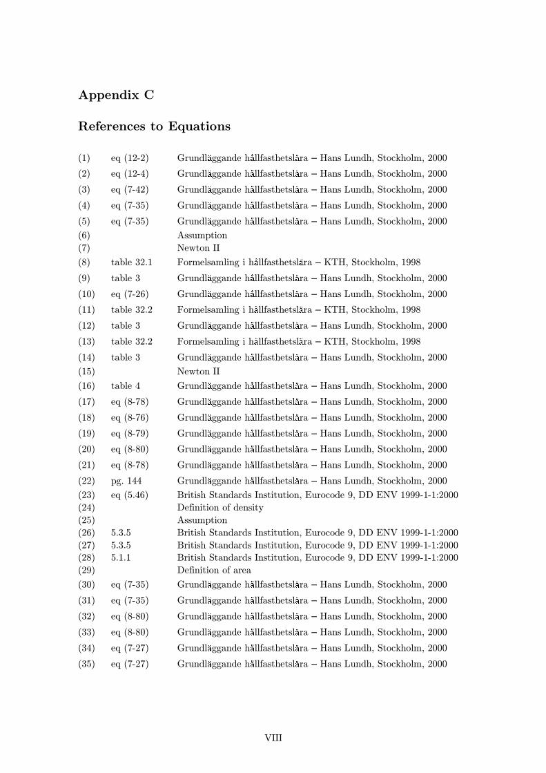
VIII
Appendix C
References to Equations
(1) eq (12-2) Grundl ggande h llfasthetsl ra – Hans Lundh, Stockholm, 2000
(2) eq (12-4) Grundl ggande h llfasthetsl ra – Hans Lundh, Stockholm, 2000
(3) eq (7-42) Grundl ggande h llfasthetsl ra – Hans Lundh, Stockholm, 2000
(4) eq (7-35) Grundl ggande h llfasthetsl ra – Hans Lundh, Stockholm, 2000
(5) eq (7-35) Grundl ggande h llfasthetsl ra – Hans Lundh, Stockholm, 2000
(6) Assumption
(7) Newton II
(8) table 32.1 Formelsamling i h llfasthetsl ra – KTH, Stockholm, 1998
(9) table 3 Grundl ggande h llfasthetsl ra – Hans Lundh, Stockholm, 2000
(10) eq (7-26) Grundl ggande h llfasthetsl ra – Hans Lundh, Stockholm, 2000
(11) table 32.2 Formelsamling i h llfasthetsl ra – KTH, Stockholm, 1998
(12) table 3 Grundl ggande h llfasthetsl ra – Hans Lundh, Stockholm, 2000
(13) table 32.2 Formelsamling i h llfasthetsl ra – KTH, Stockholm, 1998
(14) table 3 Grundl ggande h llfasthetsl ra – Hans Lundh, Stockholm, 2000
(15) Newton II
(16) table 4 Grundl ggande h llfasthetsl ra – Hans Lundh, Stockholm, 2000
(17) eq (8-78) Grundl ggande h llfasthetsl ra – Hans Lundh, Stockholm, 2000
(18) eq (8-76) Grundl ggande h llfasthetsl ra – Hans Lundh, Stockholm, 2000
(19) eq (8-79) Grundl ggande h llfasthetsl ra – Hans Lundh, Stockholm, 2000
(20) eq (8-80) Grundl ggande h llfasthetsl ra – Hans Lundh, Stockholm, 2000
(21) eq (8-78) Grundl ggande h llfasthetsl ra – Hans Lundh, Stockholm, 2000
(22) pg. 144 Grundl ggande h llfasthetsl ra – Hans Lundh, Stockholm, 2000
(23) eq (5.46) British Standards Institution, Eurocode 9, DD ENV 1999-1-1:2000
(24) Definition of density
(25) Assumption
(26) 5.3.5 British Standards Institution, Eurocode 9, DD ENV 1999-1-1:2000
(27) 5.3.5 British Standards Institution, Eurocode 9, DD ENV 1999-1-1:2000
(28) 5.1.1 British Standards Institution, Eurocode 9, DD ENV 1999-1-1:2000
(29) Definition of area
(30) eq (7-35) Grundl ggande h llfasthetsl ra – Hans Lundh, Stockholm, 2000
(31) eq (7-35) Grundl ggande h llfasthetsl ra – Hans Lundh, Stockholm, 2000
(32) eq (8-80) Grundl ggande h llfasthetsl ra – Hans Lundh, Stockholm, 2000
(33) eq (8-80) Grundl ggande h llfasthetsl ra – Hans Lundh, Stockholm, 2000
(34) eq (7-27) Grundl ggande h llfasthetsl ra – Hans Lundh, Stockholm, 2000
(35) eq (7-27) Grundl ggande h llfasthetsl ra – Hans Lundh, Stockholm, 2000
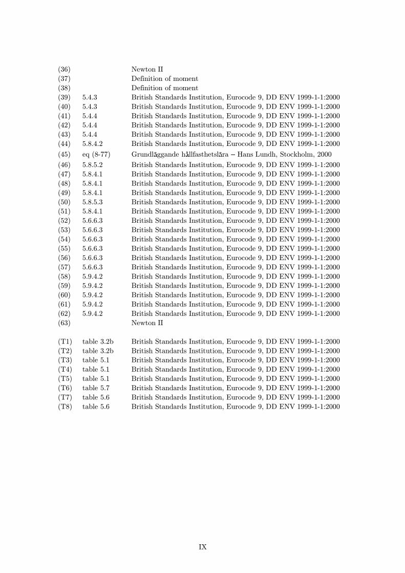
IX
(36) Newton II
(37) Definition of moment
(38) Definition of moment
(39) 5.4.3 British Standards Institution, Eurocode 9, DD ENV 1999-1-1:2000
(40) 5.4.3 British Standards Institution, Eurocode 9, DD ENV 1999-1-1:2000
(41) 5.4.4 British Standards Institution, Eurocode 9, DD ENV 1999-1-1:2000
(42) 5.4.4 British Standards Institution, Eurocode 9, DD ENV 1999-1-1:2000
(43) 5.4.4 British Standards Institution, Eurocode 9, DD ENV 1999-1-1:2000
(44) 5.8.4.2 British Standards Institution, Eurocode 9, DD ENV 1999-1-1:2000
(45) eq (8-77) Grundl ggande h llfasthetsl ra – Hans Lundh, Stockholm, 2000
(46) 5.8.5.2 British Standards Institution, Eurocode 9, DD ENV 1999-1-1:2000
(47) 5.8.4.1 British Standards Institution, Eurocode 9, DD ENV 1999-1-1:2000
(48) 5.8.4.1 British Standards Institution, Eurocode 9, DD ENV 1999-1-1:2000
(49) 5.8.4.1 British Standards Institution, Eurocode 9, DD ENV 1999-1-1:2000
(50) 5.8.5.3 British Standards Institution, Eurocode 9, DD ENV 1999-1-1:2000
(51) 5.8.4.1 British Standards Institution, Eurocode 9, DD ENV 1999-1-1:2000
(52) 5.6.6.3 British Standards Institution, Eurocode 9, DD ENV 1999-1-1:2000
(53) 5.6.6.3 British Standards Institution, Eurocode 9, DD ENV 1999-1-1:2000
(54) 5.6.6.3 British Standards Institution, Eurocode 9, DD ENV 1999-1-1:2000
(55) 5.6.6.3 British Standards Institution, Eurocode 9, DD ENV 1999-1-1:2000
(56) 5.6.6.3 British Standards Institution, Eurocode 9, DD ENV 1999-1-1:2000
(57) 5.6.6.3 British Standards Institution, Eurocode 9, DD ENV 1999-1-1:2000
(58) 5.9.4.2 British Standards Institution, Eurocode 9, DD ENV 1999-1-1:2000
(59) 5.9.4.2 British Standards Institution, Eurocode 9, DD ENV 1999-1-1:2000
(60) 5.9.4.2 British Standards Institution, Eurocode 9, DD ENV 1999-1-1:2000
(61) 5.9.4.2 British Standards Institution, Eurocode 9, DD ENV 1999-1-1:2000
(62) 5.9.4.2 British Standards Institution, Eurocode 9, DD ENV 1999-1-1:2000
(63) Newton II
(T1) table 3.2b British Standards Institution, Eurocode 9, DD ENV 1999-1-1:2000
(T2) table 3.2b British Standards Institution, Eurocode 9, DD ENV 1999-1-1:2000
(T3) table 5.1 British Standards Institution, Eurocode 9, DD ENV 1999-1-1:2000
(T4) table 5.1 British Standards Institution, Eurocode 9, DD ENV 1999-1-1:2000
(T5) table 5.1 British Standards Institution, Eurocode 9, DD ENV 1999-1-1:2000
(T6) table 5.7 British Standards Institution, Eurocode 9, DD ENV 1999-1-1:2000
(T7) table 5.6 British Standards Institution, Eurocode 9, DD ENV 1999-1-1:2000
(T8) table 5.6 British Standards Institution, Eurocode 9, DD ENV 1999-1-1:2000
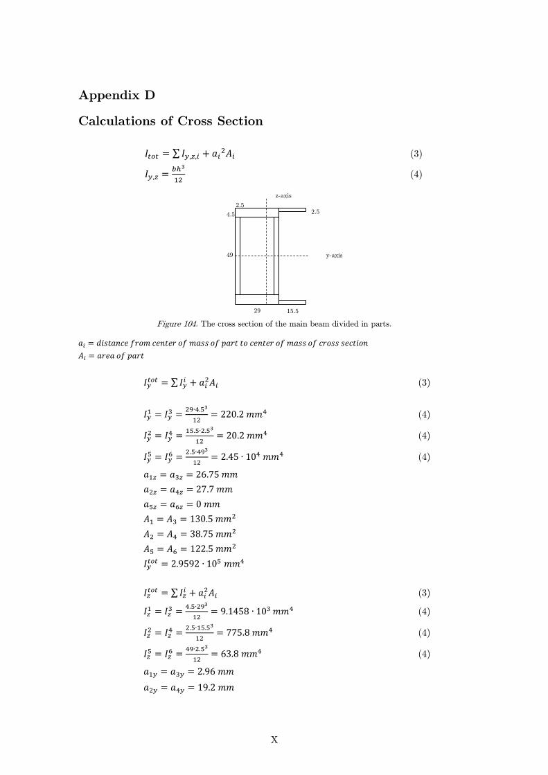
X
Appendix D
Calculations of Cross Section
∑ (3)
(4)
Figure 104. The cross section of the main beam divided in parts.
∑
(3)
(4)
(4)
(4)
∑
(3)
(4)
(4)
(4)
29 15,5
4.5
49
2.5 2.5
y-axis
z-axis

XI
The cross-section of the joist is given in Figure 14.
Figure 105. The cross section of the joist
(5)
30
53
2.5
y-axis
z-axis
XII
Eurocode 9
D.1 General Data
D.1.1 Material Properties
Material
Young’s modulus
⁄
0.2% proof strength
⁄ (T1)
Ultimate strength
⁄ (T2)
is the characteristic strength for bending and overall yielding in tension and compression
and can be defined as follows:
(26)
is the characteristic strength for the local capacity of a net section in tension or
compression and can be defined as follows:
(27)
Partial safety factor:
(28)
D.1.2 Cross Section for Main Beam
A simplification was made for the cross section of the main beam that the two projecting
flanges on the side were removed. The two projecting flanges increase the stiffness and
strength of the system, which means conservative calculations. Instead the cross section
became thin and hollow and it was therefore easier to perform the calculations, see Figure
106.

XIII
Figure 106. Simplified cross section for main beam, compare to Figure 13
Width of section
Depth of section
Wall thickness of the section
Gross area of the section
( ) ( ) (29)
Moment of Inertia
(30)
(31)
Radius of gyration
√
(32)
√
(33)
b
b1
d1 d
t1
t2
z
y

XIV
Shape factor
Section modulus about Y-axis
(34)
Section modulus about X-axis
(35)
D.1.3 Cross Section for Joist
A simplification was made that the cross section was square and that the thickness was
consistent throughout. The smallest thickness was chosen, that is because if the beam
would manage against buckling for the thinner cross section it would manage for the
thicker as well, see Figure 107.
Figure 107. Simplified cross section for joist compared to Figure 14.
Width of section
Depth of section
Wall thickness of the section
b
b1
t
z
y

XV
Gross area of the section
( ) ( ) (29)
Moment of Inertia
(30)
(31)
Radios of gyration
√
(32)
√
(33)
Shape factor
Section modulus about Y-axis
(34)
Section modulus about X-axis
(35)
D.2 Buckling Design of Main Beam
D.2.1 Design Cases
For these calculations only attachment 1 was considered. This was because the differences
between attachment 1 and 2 are not enough to make any significant impact on the results.
For the main beam there were three different cases that were studied, this was because the
beam was separated into three parts as seen in Figure 19 with either dissimilar length or
boundary conditions. The effective length factor depends on the boundary conditions and
this would therefore result in different values of the effective length. The calculations were
considering the worst case scenario, which implicates ultimate loads and added human body
mass.

XVI
Cases
Main beam – Euler 1
Main beam – Euler 3
Main beam – Euler 4
D.2.2 Loads and Moment Values
It is an empirical assumption that the moment about minor axis is taken as 10% of the
moment about major axis.
Design value of the compressive force
(36)
Since there is no predetermined point where the axial load affects, the assumptions is made
that it comes into the centre of the cross section and the eccentricity therefore becomes
zero.
Design value of the moment about YY axis
(37)
Design value of the moment about ZZ axis
(38)
D.2.3 Classification of Cross Section
This classification is performed according to 5.4 in Eurocode 9.
Slenderness parameter
(39)
(40)
√
(41)
Since this member is non heat treated and unwelded
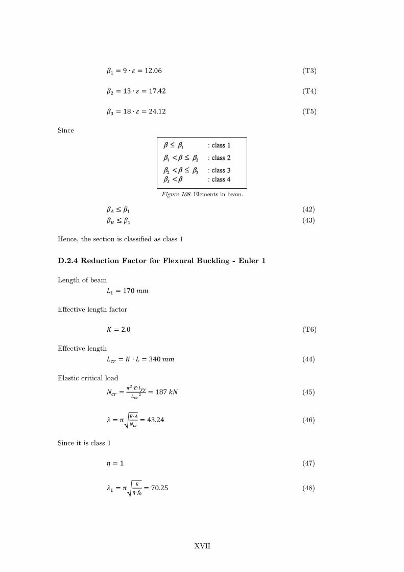
XVII
(T3)
(T4)
(T5)
Since
Figure 108. Elements in beam.
(42)
(43)
Hence, the section is classified as class 1
D.2.4 Reduction Factor for Flexural Buckling - Euler 1
Length of beam
Effective length factor
(T6)
Effective length
(44)
Elastic critical load
(45)
√
(46)
Since it is class 1
(47)
√
(48)

XVIII
(T7)
(T8)
√
(47)
( ( ) ) (50)
Reduction factor for flexural buckling
√( ) (51)
D.2.5 Reduction Factor for Flexural Buckling – Euler 3
(T6)
(44)
(45)
(47)
(48)
(T7)
(T8)
(49)
(50)
Reduction factor for flexural buckling
(51)
D.2.6 Reduction Factor for Flexural Buckling – Euler 4
(T6)
(44)
(45)
(47)
(48)
(T7)
(T8)
(49)
(50)
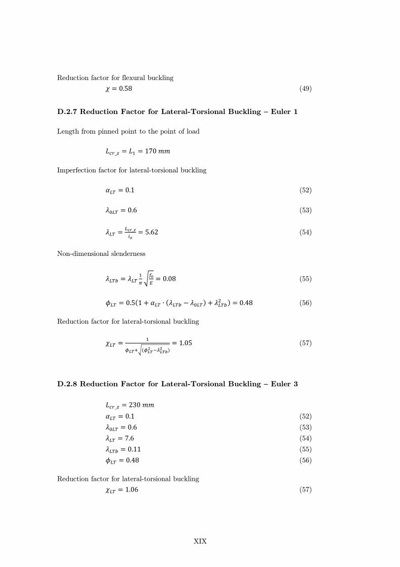
XIX
Reduction factor for flexural buckling
(49)
D.2.7 Reduction Factor for Lateral-Torsional Buckling – Euler 1
Length from pinned point to the point of load
Imperfection factor for lateral-torsional buckling
(52)
(53)
(54)
Non-dimensional slenderness
√
(55)
( ( ) ) (56)
Reduction factor for lateral-torsional buckling
√(
)
(57)
D.2.8 Reduction Factor for Lateral-Torsional Buckling – Euler 3
(52)
(53)
(54)
(55)
(56)
Reduction factor for lateral-torsional buckling
(57)
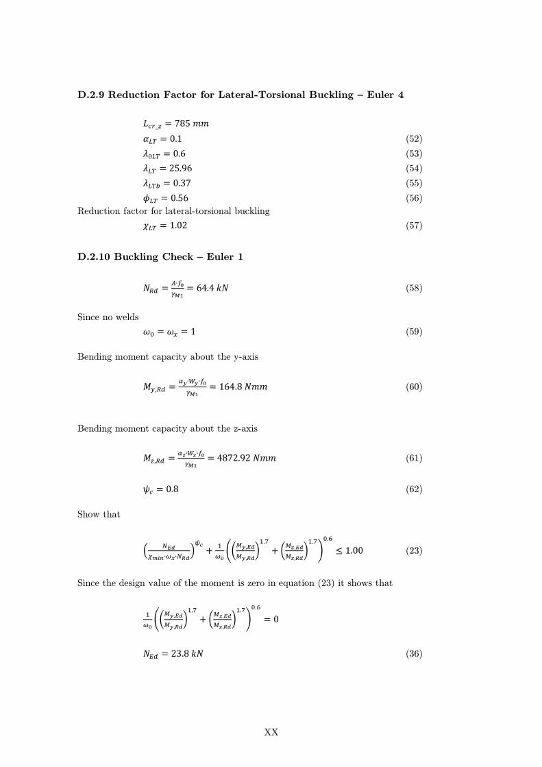
XX
D.2.9 Reduction Factor for Lateral-Torsional Buckling – Euler 4
(52)
(53)
(54)
(55)
(56)
Reduction factor for lateral-torsional buckling
(57)
D.2.10 Buckling Check – Euler 1
(58)
Since no welds
(59)
Bending moment capacity about the y-axis
(60)
Bending moment capacity about the z-axis
(61)
(62)
Show that
(
)
((
)
(
)
)
(23)
Since the design value of the moment is zero in equation (23) it shows that
((
)
(
)
)
(36)
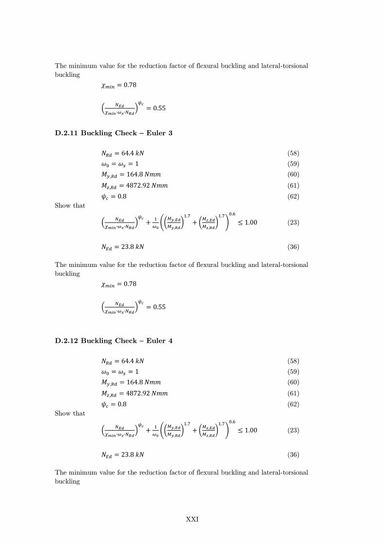
XXI
The minimum value for the reduction factor of flexural buckling and lateral-torsional
buckling
(
)
D.2.11 Buckling Check – Euler 3
(58)
(59)
(60)
(61)
(62)
Show that
(
)
((
)
(
)
)
(23)
(36)
The minimum value for the reduction factor of flexural buckling and lateral-torsional
buckling
(
)
D.2.12 Buckling Check – Euler 4
(58)
(59)
(60)
(61)
(62)
Show that
(
)
((
)
(
)
)
(23)
(36)
The minimum value for the reduction factor of flexural buckling and lateral-torsional
buckling
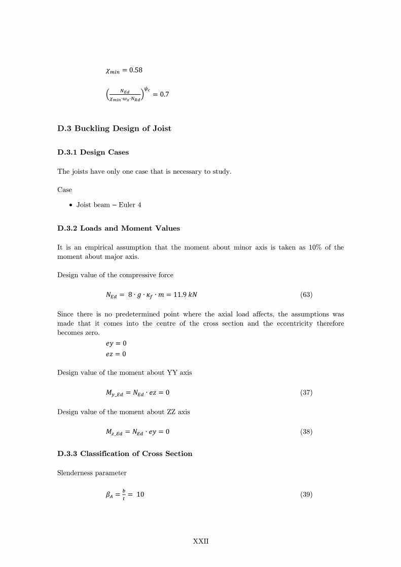
XXII
(
)
D.3 Buckling Design of Joist
D.3.1 Design Cases
The joists have only one case that is necessary to study.
Case
Joist beam – Euler 4
D.3.2 Loads and Moment Values
It is an empirical assumption that the moment about minor axis is taken as 10% of the
moment about major axis.
Design value of the compressive force
(63)
Since there is no predetermined point where the axial load affects, the assumptions was
made that it comes into the centre of the cross section and the eccentricity therefore
becomes zero.
Design value of the moment about YY axis
(37)
Design value of the moment about ZZ axis
(38)
D.3.3 Classification of Cross Section
Slenderness parameter
(39)
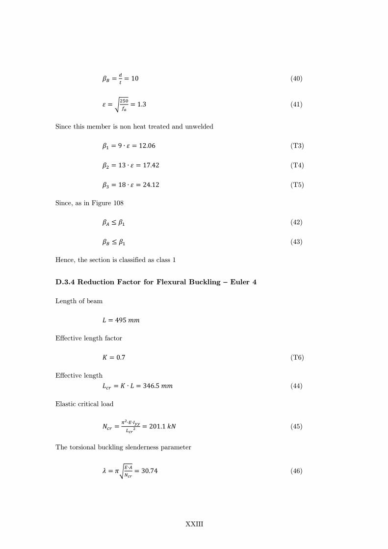
XXIII
(40)
√
(41)
Since this member is non heat treated and unwelded
(T3)
(T4)
(T5)
Since, as in Figure 108
(42)
(43)
Hence, the section is classified as class 1
D.3.4 Reduction Factor for Flexural Buckling – Euler 4
Length of beam
Effective length factor
(T6)
Effective length
(44)
Elastic critical load
(45)
The torsional buckling slenderness parameter
√
(46)

XXIV
Since it is class 1
(47)
√
(48)
Imperfection factors
(T7)
(T8)
Slenderness parameter for buckling
√
(49)
( ( ) ) (50)
Reduction factor for flexural buckling
√( ) (51)
D.3.5 Reduction Factor for Lateral-Torsional Buckling – Euler 4
Length from pinned point to the point of load
Imperfection factor for lateral-torsional buckling
(52)
(53)
(54)
Non-dimensional slenderness
√
(55)
( ( ) ) (56)
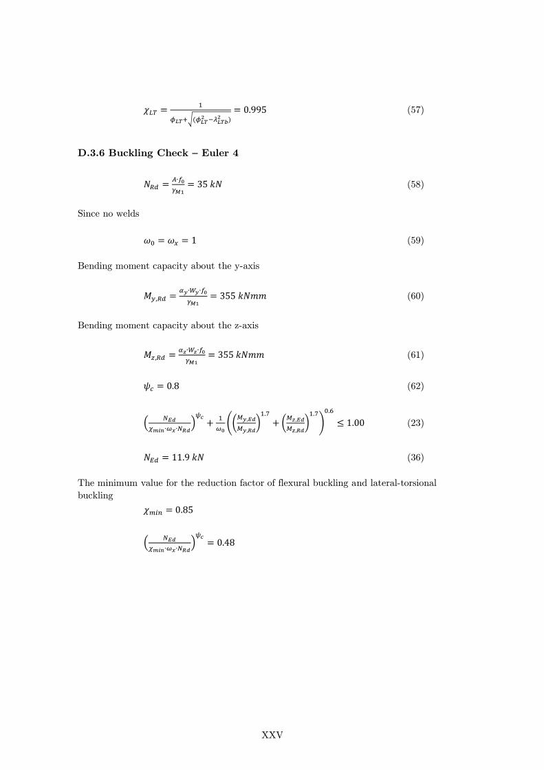
XXV
√(
)
(57)
D.3.6 Buckling Check – Euler 4
(58)
Since no welds
(59)
Bending moment capacity about the y-axis
(60)
Bending moment capacity about the z-axis
(61)
(62)
(
)
((
)
(
)
)
(23)
(36)
The minimum value for the reduction factor of flexural buckling and lateral-torsional
buckling
(
)
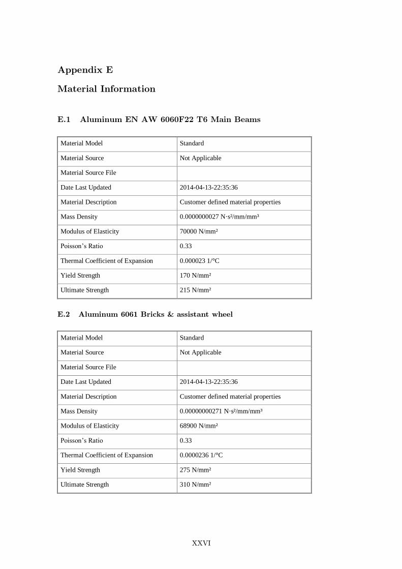
XXVI
Appendix E
Material Information
E.1 Aluminum EN AW 6060F22 T6 Main Beams
Material Model Standard
Material Source Not Applicable
Material Source File
Date Last Updated 2014-04-13-22:35:36
Material Description Customer defined material properties
Mass Density 0.0000000027 N·s²/mm/mm³
Modulus of Elasticity 70000 N/mm²
Poisson’s Ratio 0.33
Thermal Coefficient of Expansion 0.000023 1/°C
Yield Strength 170 N/mm²
Ultimate Strength 215 N/mm²
E.2 Aluminum 6061 Bricks & assistant wheel
Material Model Standard
Material Source Not Applicable
Material Source File
Date Last Updated 2014-04-13-22:35:36
Material Description Customer defined material properties
Mass Density 0.00000000271 N·s²/mm/mm³
Modulus of Elasticity 68900 N/mm²
Poisson’s Ratio 0.33
Thermal Coefficient of Expansion 0.0000236 1/°C
Yield Strength 275 N/mm²
Ultimate Strength 310 N/mm²
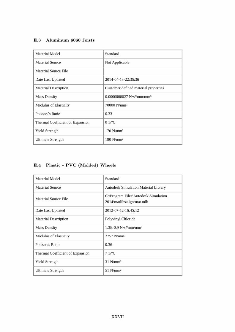
XXVII
E.3 Aluminum 6060 Joists
Material Model Standard
Material Source Not Applicable
Material Source File
Date Last Updated 2014-04-13-22:35:36
Material Description Customer defined material properties
Mass Density 0.0000000027 N·s²/mm/mm³
Modulus of Elasticity 70000 N/mm²
Poisson’s Ratio 0.33
Thermal Coefficient of Expansion 0 1/°C
Yield Strength 170 N/mm²
Ultimate Strength 190 N/mm²
E.4 Plastic - PVC (Molded) Wheels
Material Model Standard
Material Source Autodesk Simulation Material Library
Material Source File C:\Program Files\Autodesk\Simulation
2014\matlibs\algormat.mlb
Date Last Updated 2012-07-12-16:45:12
Material Description Polyvinyl Chloride
Mass Density 1.3E-0.9 N·s²/mm/mm³
Modulus of Elasticity 2757 N/mm²
Poisson's Ratio 0.36
Thermal Coefficient of Expansion 7 1/°C
Yield Strength 31 N/mm²
Ultimate Strength 51 N/mm²

XXVIII
E.5 Steel mild - Joints
Material Model Standard
Material Source Not Applicable
Material Source File
Date Last Updated 2014-04-13-22:35:36
Material Description Customer defined material properties
Mass Density 0.00000000786 N·s²/mm/mm³
Modulus of Elasticity 220000 N/mm²
Poisson's Ratio 0.275
Thermal Coefficient of Expansion 0 1/°C
Yield Strength 207 N/mm²
Ultimate Strength 345 N/mm²
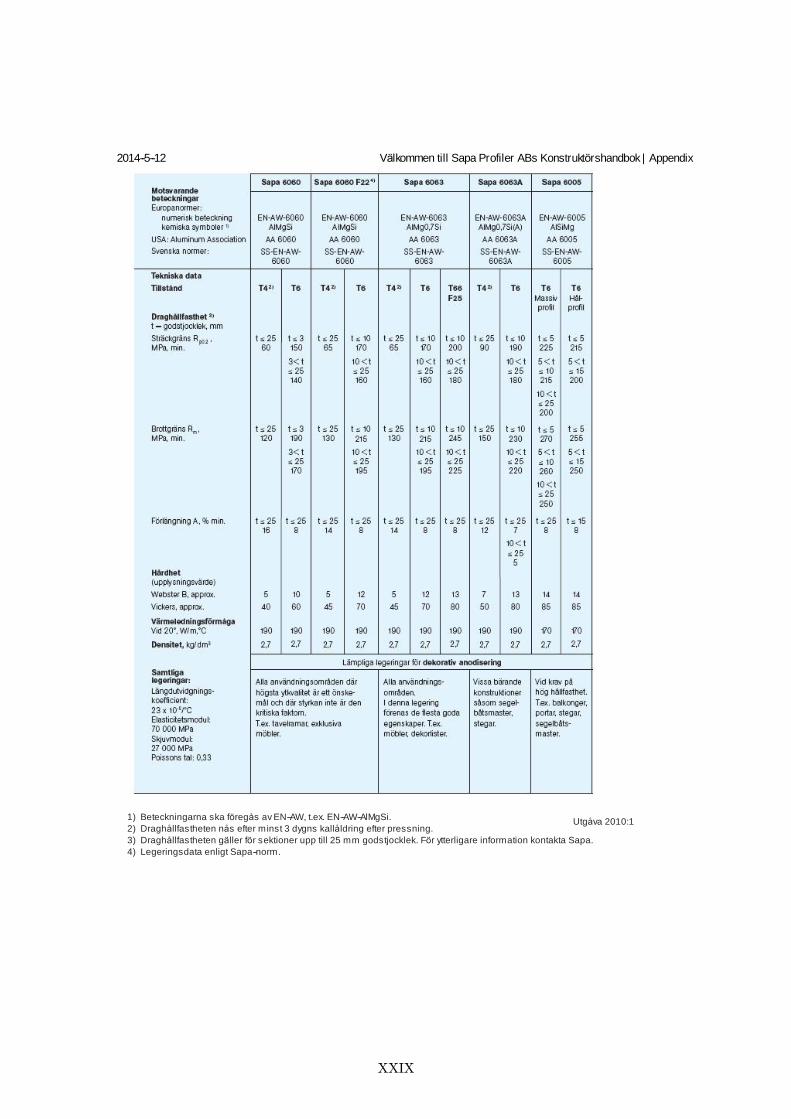
XXIX
2014-5-12 Välkommen till Sapa Profiler ABs Konstruktörshandbok | Appendix
http://handboken.sapagroup.com/konstruktoershandboken/appendix.aspx/print 2/4
Utgåva 2010:1
1) Beteckningarna ska föregås av EN-AW, t.ex. EN-AW-AlMgSi.
2) Draghållfastheten nås efter minst 3 dygns kallåldring efter pressning.
3) Draghållfastheten gäller för sektioner upp till 25 mm godstjocklek. För ytterligare information kontakta Sapa.
4) Legeringsdata enligt Sapa-norm.
XXX
XXXI

XXXII
Appendix F
Matrices
COMBINATION OF CONCEPTS
A B C D E F G
1
x x x
2 x x x x x x x
3 x x x x x x x
4 x x x x x x x

XXXIII
C
ON
CE
PT
S
Mee
t all r
equir
emen
ts
Rea
liza
ble
Safe
Erg
onom
ic
Easy
to u
se
Elimination Matrix
(+) Yes
(-) No
(?) More information is required
Comments Decision
A2 + + + + + Keep
A3 + -
Liquid container
A4 -
Two directions not possible
B1 + + + + + Keep
B2 + + + + + Keep
B3 ? -
Height, Liquid container
B4 -
Two directions not possible
C1 + + + + + Keep
C2 + + + + + Keep
C3 + -
Liquid container
C4 -
Two directions not possible
D1 + + + + + Keep
D2 + + + + + Keep
D3 + -
Liquid container
D4 -
Two directions not possible
E2 + + + + + Keep
E3 + -
Liquid container
E4 -
Two directions not possible
F2 + + + + + Keep
F3 + -
Liquid container
F4 -
Two directions not possible
G2 + + + + + Keep
G3 + -
Liquid container
G4 -
Two directions not possible
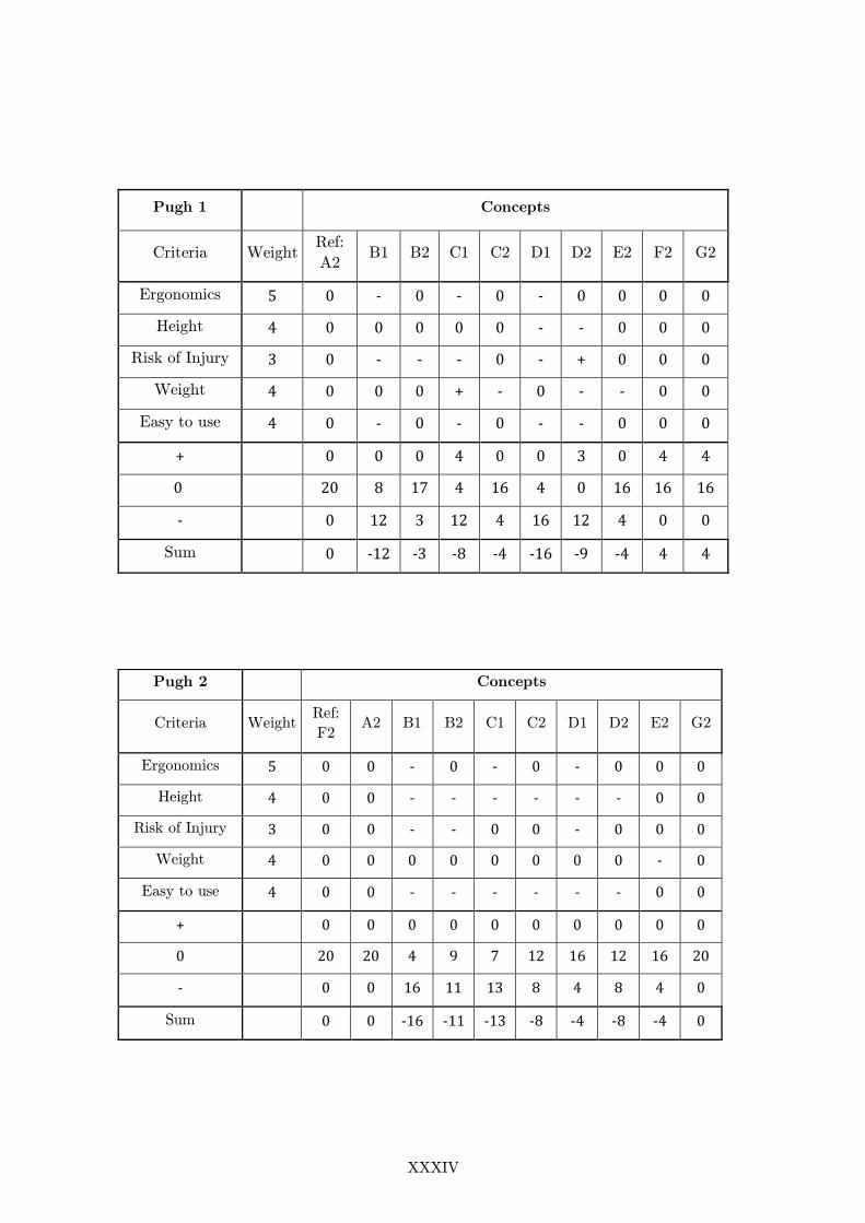
XXXIV
Pugh 1
Concepts
Criteria Weight Ref:
A2 B1 B2 C1 C2 D1 D2 E2 F2 G2
Ergonomics 5 0 - 0 - 0 - 0 0 0 0
Height 4 0 0 0 0 0 - - 0 0 0
Risk of Injury 3 0 - - - 0 - + 0 0 0
Weight 4 0 0 0 + - 0 - - 0 0
Easy to use 4 0 - 0 - 0 - - 0 0 0
+
0 0 0 4 0 0 3 0 4 4
0
20 8 17 4 16 4 0 16 16 16
-
0 12 3 12 4 16 12 4 0 0
Sum
0 -12 -3 -8 -4 -16 -9 -4 4 4
Pugh 2
Concepts
Criteria Weight Ref:
F2 A2 B1 B2 C1 C2 D1 D2 E2 G2
Ergonomics 5 0 0 - 0 - 0 - 0 0 0
Height 4 0 0 - - - - - - 0 0
Risk of Injury 3 0 0 - - 0 0 - 0 0 0
Weight 4 0 0 0 0 0 0 0 0 - 0
Easy to use 4 0 0 - - - - - - 0 0
+
0 0 0 0 0 0 0 0 0 0
0
20 20 4 9 7 12 16 12 16 20
-
0 0 16 11 13 8 4 8 4 0
Sum
0 0 -16 -11 -13 -8 -4 -8 -4 0
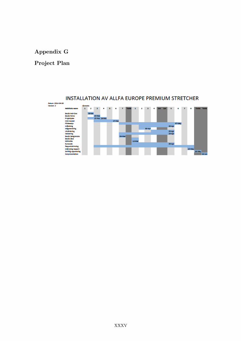
XXXV
Appendix G
Project Plan

XXXVI
Appendix H
Bill of material
The following pages contain the bill of material.
XXXVII
Appendix I
Drawings
The following pages contain drawings of significant parts of the stretcher.