installation of a plasmatron at the belgian nuclear research centre and its use for plasma-wall...
TRANSCRIPT
Installation of a Plasmatron at the
Belgian Nuclear Research Centre and its use for
Plasma-Wall Interaction Studies
I. Uytdenhouwen, J. Schuurmans, M. Decréton, V. MassautSCK●CEN, Mol, Belgium
G. Van OostGhent University, Belgium
Key issues in PWI
Dedicated research facilities
Plasmatron facility VISION I
Conclusion
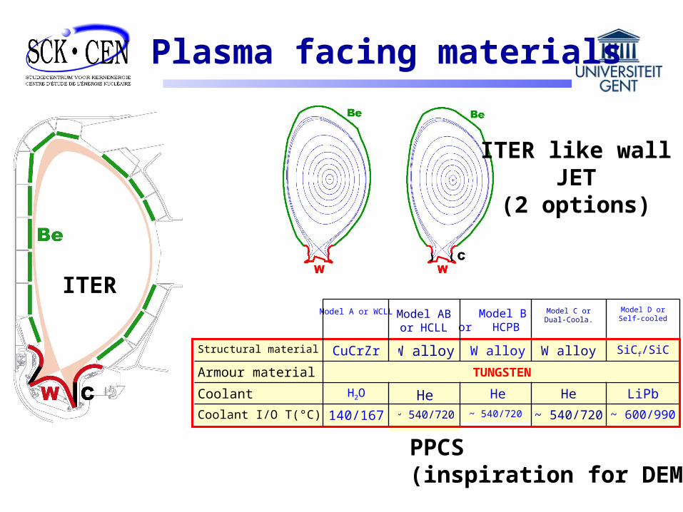
ITER
ITER like wallJET
(2 options)
PPCS (inspiration for DEMO)
W alloy
~ 540/720
He~ 600/990~ 540/720~ 540/720140/167Coolant I/O T(°C)
LiPbHeHeH2OCoolant
Armour material
SiCf/SiCW alloyW alloyCuCrZrStructural material
Model D or Self-cooled
Model C or Dual-Coola.
Model B or HCPB
Model A or WCLL
Model ABor HCLL
TUNGSTEN
Plasma facing materials

Low Z, high oxygen gettering, good thermal conductivity, low solubility for hydrogen
Implantation with D, T (saturated very-near surface layers)
Beryllium
Radiation
Dilution
Loarte A. et al., NF 47 (2007)Causey R.A. et al., Fus. Eng. Des. 61 (2002)
BUT Nuclear reactions breed T, He in bulk High erosion yield
Low melting pointRES (radiation enhanced sublimation) ionized Be in the plasma deposition in divertor area mixed materials issue (alloy formation)

Mixed materials
Atomic percent Tungsten
0 10 20 30 40 50 60 70 80 90 100
Tem
pera
ture
(o
C)
1000
2000
3000
Weight percent Tungsten
0 70 80 90 100
Be W
34
22
o C
LIQUID
Be
12W Be
2W
<1750o C
<2250o C
12
87
o C
Be
22W
~952100 50o C
Stable Be-W alloys
Stable Be-W intermetallics are: ~2200°C (Be2W)
~1500°C (Be12W)
~1300°C (Be22W)
melting points closer to Be than to W!
Baldwin M. et al., J. Nucl. Mat. 363 (2007)
What happens if Be transport into the W bulk is rapid enough that alloy formation is not limited to the near surface?

Low Z (low central radiation, radiation in boundary)Good thermomechanical properties Lack of melting
Graphite
Causey R.A. et al., Fus. Eng. Des. 61 (2002)Shimomura Y., J. Nucl. Mat. 363 (2007)
BUT T retention issue
co-depositions (surface) depositions in gaps n damage (bulk)
Destruction by neutrons High erosion yield
CW
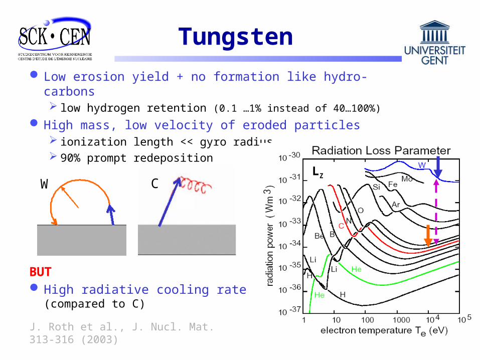
Low erosion yield + no formation like hydro-carbons low hydrogen retention (0.1 …1% instead of 40…100%)
High mass, low velocity of eroded particles ionization length << gyro radius 90% prompt redeposition
J. Roth et al., J. Nucl. Mat. 313-316 (2003)
Tungsten
LZ
BUT High radiative cooling rate
(compared to C)

Only limited concentration in plasma allowed (ppm range) Limit W erosion (transients, sputtering, …) High-Z impurity control by seeding with Ar, Ne
Tungsten
Sputtering yield by D negligible(100-1000 times smaller as for C)
Federici G. et al., J. Nucl. Mat. 313 (2003)
BUT Strongly dominated by
Low-Z intrinsic impurities Higher sputtering by Ar, Ne Mixed materials issue
(even if only one PFM)
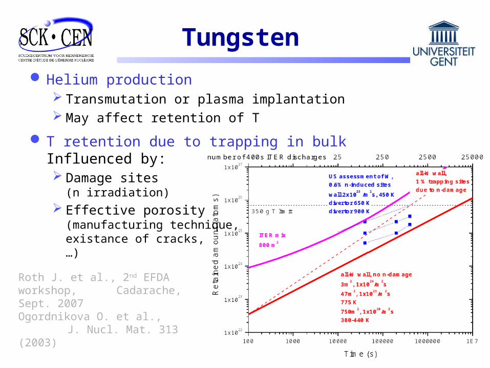
Helium production Transmutation or plasma implantation May affect retention of T
Tungsten
Roth J. et al., 2nd EFDA workshop, Cadarache, Sept. 2007Ogordnikova O. et al.,
J. Nucl. Mat. 313 (2003)
T retention due to trapping in bulkInfluenced by: Damage sites
(n irradiation) Effective porosity
(manufacturing technique, existance of cracks, …)
Tritium retention
Kunz C. et al., J. Nucl. Mat. 367 (2007)
Tritium removal shemes(min. interference with plasma operation & performance) Heating in air or oxygen Laser heating flash lamps He-O glow discharges
Predictions needed for licensing Improvement in trapping/retention modelingneeds to be validated by experiments
Retention diagnostics needed
Minimize T inventory in the co-deposits (material choice, erosion limitation, …)

Other issues
Shimomura Y., J. Nucl. Mat. 363 (2007)
Degradation of in-vessel diagnostic components Dust Material deposition Erosion Neutron damage
Avoidance (material choice, …)
Limitation (removal methods, …)
Dust Major Safety issue for licensing (Be:toxic, C:tritium, W: active) Reaction with water leakage and H production (co-deposits) Reaction with air (vacuum leakage)
Dust generation/characteristics must be understood,
Diagnositcs needed (quantification),
In-situ removal methods
Key issues in PWI
Dedicated research facilities
Plasmatron facility VISION I
Conclusion
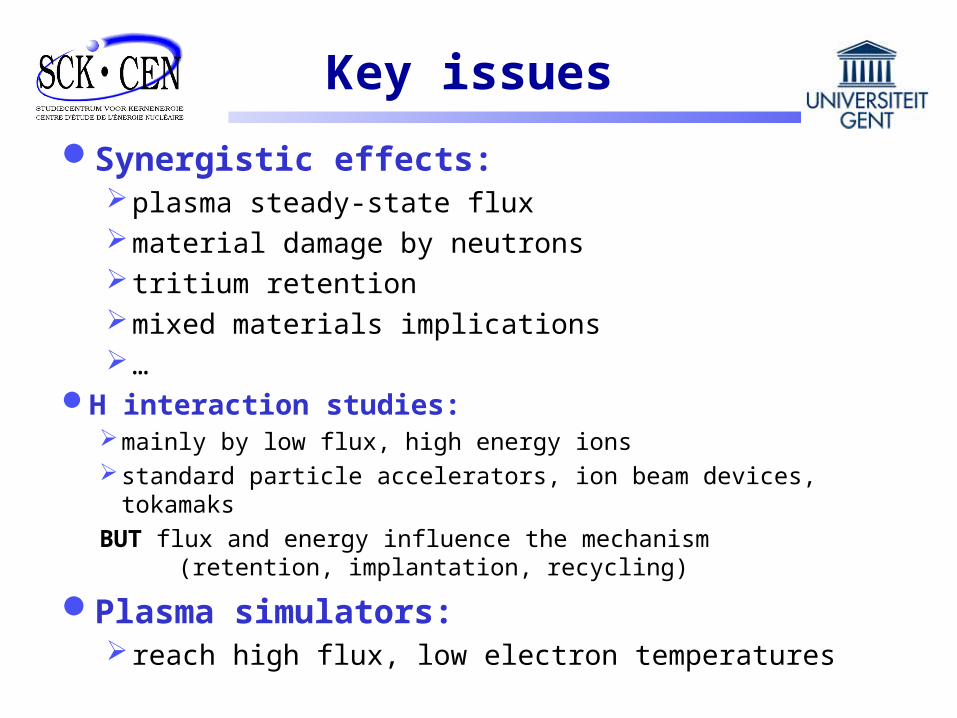
Synergistic effects: plasma steady-state fluxmaterial damage by neutrons tritium retentionmixed materials implications…
Key issues
Plasma simulators: reach high flux, low electron temperatures
H interaction studies:mainly by low flux, high energy ionsstandard particle accelerators, ion beam devices, tokamaks
BUT flux and energy influence the mechanism (retention, implantation, recycling)
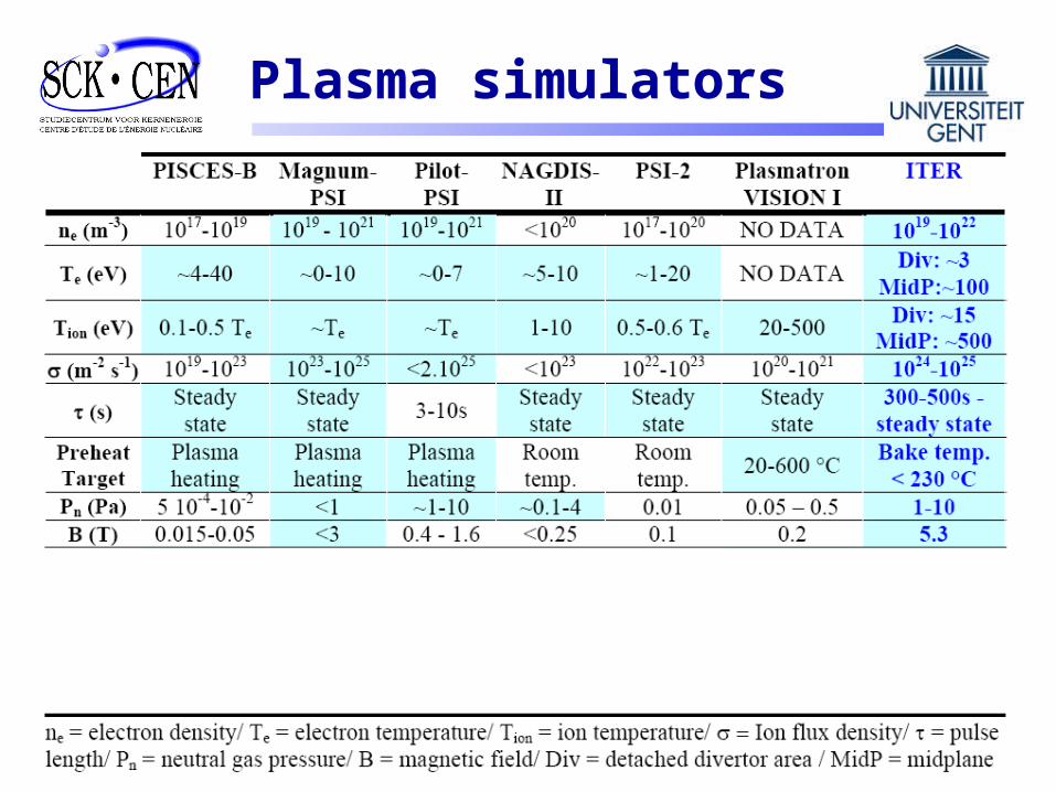
Plasma simulators
SCK•CEN
Due to difficulties inherent to: transportcharacterization
of tritium, beryllium and neutron activated materials
It is advantageous to have devices (Plasmatron VISION I) in-house characterization tools
(tritium lab., beryllium cells, hot cells)knowledge and experience (BR2 matrix, fission, …)
at the same location
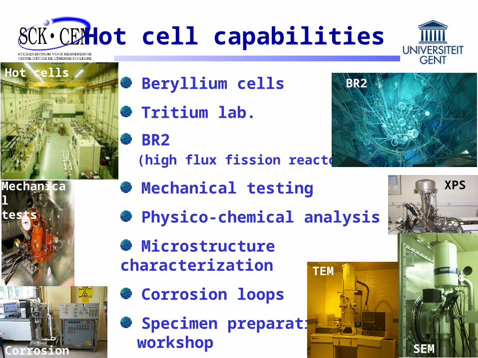
Beryllium cells
Tritium lab.
BR2 (high flux fission reactor)
Mechanical testing
Physico-chemical analysis
Microstructure characterization
Corrosion loops
Specimen preparation workshop
Hot cell capabilities
BR2
XPS
SEM
Mechanical
tests
TEM
Corrosion
Hot cells
Key issues in PWI
Dedicated research facilities
Plasmatron facility VISION I
Conclusion

ETHEL: the JRC experimental program (Ispra, Italy,1993)European Tritium Handling Experimental Laboratory
Shut down ten years agoDue to decommissioning of ETHEL buildings
Contract between SCK•CEN and JRC to transport plasmatronSeveral parts of equipment is missing
(were used for other projects)
Reinstallation at SCK•CEN for fusion applicationsRefurbishment/recovery will be done in 2008Most of technical documents were found in JRC archive
Background / History
New nameplasmatron VISION I
(Versatile Instrument for the Study of ION Interaction I)
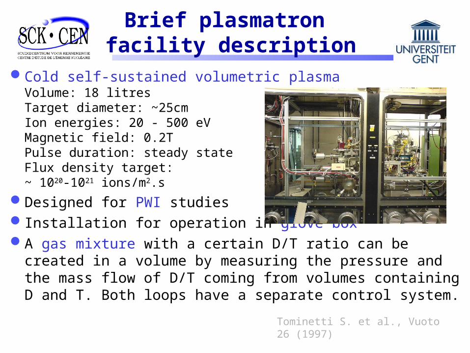
Cold self-sustained volumetric plasmaVolume: 18 litres Target diameter: ~25cm Ion energies: 20 - 500 eVMagnetic field: 0.2T Pulse duration: steady stateFlux density target: ~ 1020-1021 ions/m2.s
Designed for PWI studies Installation for operation in glove boxA gas mixture with a certain D/T ratio can be created in a
volume by measuring the pressure and the mass flow of D/T coming from volumes containing D and T. Both loops have a separate control system.
Brief plasmatron facility description
Tominetti S. et al., Vuoto 26 (1997)
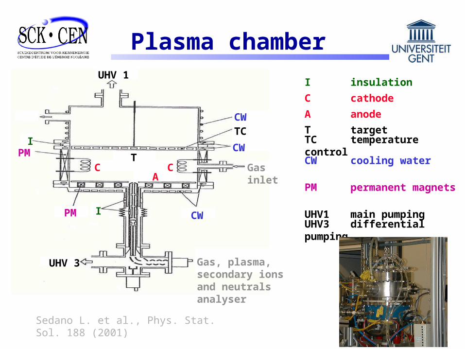
Plasma chamber
Gas, plasma, secondary ions and neutrals analyser
Gas inlet
CW
CW
CW
CW cooling water
TC
TC temperature control
I
I
I insulation
PM
PM
PM permanent magnets
T
T target
C CA
C cathode
A anode
UHV 1
UHV1 main pumping
UHV 3
UHV3 differential pumping
Sedano L. et al., Phys. Stat. Sol. 188 (2001)

Key issues in PWI
Dedicated research facilities
Plasmatron facility VISION I
Conclusion
Conclusion
Key issues determined by synergistic effects (steady state flux, transient loads, neutron damage)
Plasmatron VISION I can address several of these key issues because tritium beryllium neutron irradiated materialscan be studied under high flux densities, low plasma temperatures
PFM requirements for ITER/DEMO
• R&D programme: fabrication feasibility, resilience to neutron damage, activation, …
• BUT performance/use depends also on:T-retention, dust production, resilience to large steady-state fluences, transient loads, surface erosion, material redeposition

Thank you for your attention
Any questions?