installation manual z-100
TRANSCRIPT

EO:7788CR E V 0 1 4/21/16
Z-1002200 lb. Liftgates
80117601
Installation Manual
Phone: 800.411.5685
Fax: 800.411.5684
Waltco Lift Corp.
Corporate Offi ce United States
285 Northeast Ave.Tallmadge, OH 44278P: 330.633.9191F: 330.633.1418
Waltco Lift Corp.
United States
620 Hambledon Ave.City of Industry, CA 91744P: 626.964.0990F: 626.964.0149
Waltco Lift Inc.
Canada
265 Export Blvd.Mississauga, ON L5S 1Y4 P: 800.982.1632


Contents
1. CE marking............................................................................................................ 4
2. General .................................................................................................................. 5
3. Mounting kits, list of ..............................................................................................7
4. Introduction and order of mounting operations .................................................9
5. Installation of support frame ..............................................................................10
6. Installation, hydraulics........................................................................................14
7. Electrical installation...........................................................................................16
8. Installation, platform ...........................................................................................20
9. Installation, cylinders, adjustments...................................................................22
10. Installation, other...............................................................................................25
11. Important information .......................................................................................26
12. Markings, decals................................................................................................27
13. Torque measures ...............................................................................................28
14. Maintenance, lubrication chart.........................................................................29
15. Dismantling ........................................................................................................32
16. Schedules, tables, diagrams ............................................................................33
1. Max power consumption, Loading diagram .............................................34
2. Dimensions for installation ........................................................................35
3. Electric and hydraulic diagram ..................................................................37
4. Connection unit ...........................................................................................41

4
Since 1/1/1995 ZEPRO tail lifts sold to the European market are stamped with a CE mark. This is the manufacturer's guarantee that the product conforms to the European Machinery Directive. Waltco stands behind this guarantee.
The application of the European Machinery Directive is intended to harmonize product safety levels across Europe.
There are some general principals that should be made clear when performing the installation of ZEPRO/Waltco lifts.
Follow the installation instructions. If it is not possible to follow the installation instructions or if modifi cations are required, the modifi cations must be approved by the manufacturer. This is a consequence of the CE marking regulations as it cannot be possible for a manufacturer to certify conformity to the Machinery Directive if the product is subsequently changed without his knowledge or approval. In order for the product's CE marking to remain applicable the forms supplied by ZEPRO/Waltco must be completed in case of modifi cation.
Welding is not necessary unless specifi cally recommended by the manufacturer.
In order to increase security, additional decals, which are diagrammatic and easily understood independent of language will be sent with the lifts. Ensure that these decals are affi xed so that the information contained on them is available for all users of the lift.
Position the control unit to ensure that the operator has a good view of the load, the working area and the loading area, whilst maintaining a safe distance from the risk zone between the platform and the body. Follow the operator’s instructions for use of the control unit and its functions.
1. CE marking

5
The ZEPRO/Waltco-lift is electro-hydraulically driven. An electric motor which gets its power from the truck's ordinary battery drives a hydraulic pump which supplies oil via hoses and pipes to the working hydraulic cylinders. The system is steered by electrical valves.The hydraulic power unit and the control system with all details is built into a separate box. Both systems are easy to reach for service and maintenance.The platform is supported by the lift arm which is very strong and rigid. The under run protection bar is directly attached to the support frame. The platform has a non-slip surface.The lift arm lifting work is done by lift cylinders which have built in safety valves for protection against hose breakage. The lift cylinder circuit is equipped with 1 or 2 electric safety valves, which are leakproof. These safety valves can also act as an extra transport lock for the platform. The valves are built into the cylinders.The platform's tilt function is also provided by cylinders with similar design to the lift cylinders. Tilt cylinders can have one speed operation. The tilt cylinder circuit is also equipped with 1 or 2 electric safety valves. Lifting and tilting up and down speeds are fi xed by the pump capacity. Lowering speed are controlled by a special constant fl ow valve. These valve give the same speed independent of the load.The cylinder piston rods are treated with carbon nitrating which gives them very long life.The hydraulic system is protected with a pressure regulator when lifting or tilting up. Note! This regulator does not prevent overload at
rest position or lowering.
The electric power is taken from the truck's ordinary starter motor. Control current is taken from the dash board. When the control current's isolator (cabin) switch is off, the lift is "locked". Fixed control units are electrically heated to prevent condensation damage to switches. To save current the control current should be switched off when the lift is not used.The lift can also be operated from other, optional units.To ensure safe operation even with very long control cables, the hydraulic unit is equipped with relays. The relays situated in the electrical connection box placed in the support frame steer current directly from the main cable to the valves and the main switch for the motor.The electric motor is equipped with a thermostat which breaks the current if the motor becomes overheated. The motor will stop until it is cool again. The platform can be tilted to all positions from vertical to 10° below the horizontal. It has a mechanical or electric lock which must be activating during transport.
Hydraulic oilA tail lift should operate just as well in tropical as in arctic climates. Heat does not adversely affect the hydraulic oil, however, low temperatures are more critical. Waltco therefore supplies a hydraulic oil that meets the demands across the temperature range. ZEPRO oil (art. no 21963 for 1 litre) is made of a highly refi ned mineral oil, the lubricant additive is free from zinc and gives good protection against component wear. The hydraulic oil’s low temperature properties and high viscosity index allow hydraulic system start in a very cold climate and give reliable functioning with varying temperature conditions. With ZEPRO oil the hydraulic system also receives a very good protection against corrosion.
ZEPRO also has a biologically degradable oil (art.no 22235 for 1 litre) available which is based on a synthetic base oil. This also provides very good properties at low and high temperatures. It is even liquid down to -50° C. Resistance to oxidation is extremely good which gives long lifetime with longer intervals between oil changes. Good fi ltration and air separation together with low density make the oil easy to pump. This minimizes risk for cavitation and development of scum. Contact us for more information.
2. General
Technical description
NOTE: Neither ATF nor HF oil should be used in the ZEPRO hydraulic circuit as they can damage the rub-ber in the sealing kits and reduce their lifetime.

6
Z = Standard model
Max lift capacity x 10 (kg)
Max lift height x 10 (mm) Cylindermodel, SA = Single Acting One Speed Adjustable Tilt Single Acting One Speed Lift
2. General
Lift naming
Some components of the tail lift must be manipulated by other lifting equipment during handling and therefore could represent hazards if their weights exceed the equipment's permitted load. The following are the ranges of weights for various heavy components.
Weights
Cpl. Lift chassis (without platform)
Z-100-110 370 lbs
E.g Z - 100 - 110 SA _ _ _ - _ _ _ - _ _ _ _ _
Lift components (part of cpl. lift chassis).
Support frame Z-100-110/130 85 lbsLift arm Z-100-110 75 lbsMounting bracket cpl. 8.8 lbsHydraulic unit 30.9 lbsLift cylinder -110 17.6 lbs/unit.Tilt cylinder -110 26.5 lbs/unit.Bumper bar cpl. 72.8 lbs
Aluminium platform
Flat 1-3/16 in Laser (PLALAS L)
Alu. platform 36x93 in 129 lbsAlu. platform 47x93 in 172 lbsAlu. platform 60x93 in 207 lbs

7
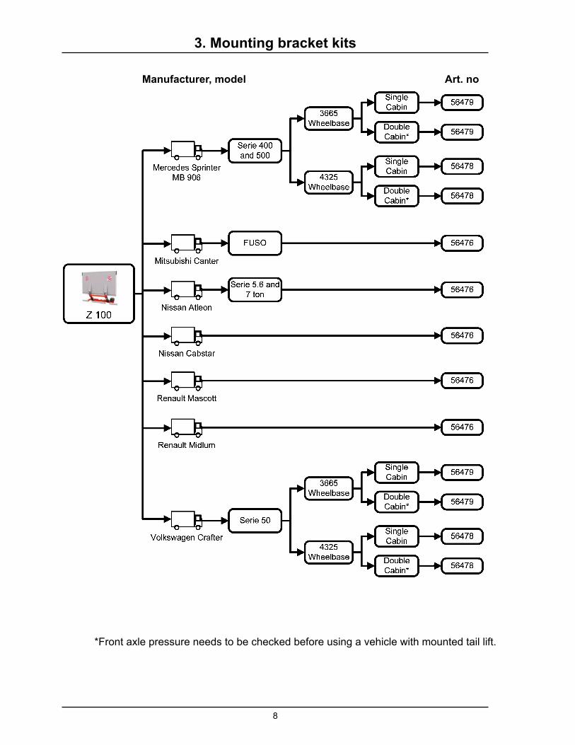
3. Mounting bracket kits
Art. noManufacturer, model
8
3. Mounting bracket kits
Art. noManufacturer, model
*Front axle pressure needs to be checked before using a vehicle with mounted tail lift.

9
4. Introduction and Order of installation operations
Attention! Also refer to the truck manufacturer´s instructions for auxiliary equipment.
WARNING! Installation where a platform or lift arm support surface does NOT reach the ground when
the platform is fully lowered is forbidden.
WARNING! Waltco Z-100 tail-lift can only be mounted with mounting kit supplied or approved by
Waltco.
Order of installation operations
Installation of support frame, standard
• Determine dimensions for installation• Fasten the jig to the rear frame• Position the support frame • Mounting brackets, standard• Loosen the jigInstallation of support frame, with mounting
bracket kit
• Determine dimensions for installation• Fasten the jig to the rear frame• See separate instruction for mounting bracket kit • Loosen the jig
Mounting hydraulics (if not premounted)
• Install hydraulic power unit• Connect the hydraulic hoses
Electrical installation
• Install control units• Connection, control cable• Connection, main power cable
Mounting platform
• Mounting platform• Mounting sealing system• Mounting armstop
Mounting cylinders
• Adjusting the tilt cylinder• Test run
Mounting, other
Mounting decals
Introduction
To make the installation easier it is wise to in advance determine the actual space available for the mounting of the lift.First determine the C-measure and then read off the other distances from the table relevant to the tail lift model.
If a mounting bracket kit is to be used, the dimensions for installation are found in the separate installation instruction for the kit.See a list of available mounting kits.
If standard brackets are used for the installation, the dimensions can be found in the current text and in the last section of this instruction booklet.

10
6-¾
C
1-½D
maxmin
A
max21-¾
43 maxH
C A D
21-¾ 5-¾ 17-¾
19-¾ 5-¼ 20
17-¾ 4-¾ 22
15-¾ 4-½ 23-½
13-¾ 4-¼ 24-¾
11-¾ 4 25-¾
~ 3 in
~ 3 in
5. Installation of support frame
1. Determine the dimensions for
installation
First determine the C-measure and then read off the other distances from the table relevant to the tail lift model. The support frame ought to be positioned as high as possible. Note the measures in the tables.
C-measure is the space between the body fl oor
level and the top of the lift support frame.
This is the most important distance.
When the C-measure is known, the A- and D-
measures may be obtained from a table. D-measure
will determine the horizontal distance which is
required for the tail-lift, and A-measure describes
the distance between the lift arms and the body fl oor
level.
D-measure is the required space for the tail lift,
measured from the back frame of the truck to the
front of the lift support frame (in the direction of the
travel).
Get the D-measure from tables when the C-distance
is known.
A-measure is the space the lift allows for the truck
rear frame, i.e. the distance between the lift arms
and the body fl oor level, when the lift arms are in
the upper position. A-measure depends on the
C-measure.
H- distance is body fl oor height from the ground (when
unloaded), and must be less than tail-lift's max lifting
height.
Installation where a platform or lift arm support
surface does NOT reach the ground when the
platform is fully lowered is forbidden.
NOTE! The mounting brackets are in two pieces
and should be fastened to each other above the
lift support frame by using screws. NOTE: This will
affect the space available between the lift and the
truck frame.
Take this into account when calculating the
C-measure.
Lift height 43 in, Z-100-110
Pic. 1
Pic. 2

11
3. Position the support frame
Place the support frame of the lift under the truck frame and fi t the lift arms to the installation jig. Use the specifi ed platform pivot bolt.
The support frame must be parallel with the chassis frame. If it is diffi cult to get the support frame into the correct position, loosen a hydraulic hose from one lift cylinder to let oil or air out.
For trucks with mounting brackets kits, see separate installation instructions. See list, section 3.
Position the support frame as required under the truck's chassis frame. eg. A wheeled jack can be used.
Mounting jig,
Art. nr. 56338 for Z-100 with sealingArt. nr 56428 for Z-100 without sealling
Measures and pictures, see section 17.2
2. Fasten the jig to the rear frame
Measure out and mark the centre point of the truck's rear frame.
Check the A-measure, to determine if cut-outs are needed in the rear frame. (See marked area in the picture).
Make the cut-outs as required in the rear beam in accordance with the measures for the relevant lift model.
Fasten the jig with bolts or spot weld it to the rear frame so that the centre points line up.
5. Installation of support frame
Pic. 3
Pic. 4
Pic. 5

12
5. Installation of support frame
Minimun overlap:
6-holes
2 nuts
M22 8.8
190 ft lbs Pic. 6
Pic. 7
Pic. 8
Pic. 9
Big bracket
Small bracket
4. Mounting brackets, standard.
The mounting brackets are made up of two parts. One bigger bracket, that should be tightly fastened to the truck body frame. The smaller bracket should be mounted on the lift support frame, and can be adjusted along its width. The two brackets are to be fastened to each other, with as small displacement (forward-backward) as possible.
Preliminarily position the smaller bracket according to picture and fasten the two brackets to each other with screws. Use the washer between bracket and nuts. Check that there is a minimum of 6 holes overlap of the smaller bracket's row of holes.
The smaller bracket can be assembled in different ways depending on the width of the truck frame. The place along the truck frame where the bracket shall be assembled is the trucks frame width.
1. If the width of the truck frame being below 30 in, the brackets shall be installed according to pic. 8 with the U-profi les end plate installed in the journey direction of the truck and the end plate leaning from the middle of the truck. (Pic. 8) 2. If the truck frames width exceeds 37 in shall the smaller brackets be installed according to pic. 9 with the U-profi les end plate installed in the journey direction of the truck and the end plate leaning to the middle of the truck. (Pic. 9)
3. If the truck frames width lies between 30-37 in, the brackets can be installed at an optional way.
End plate
Washer
13
1 2 3
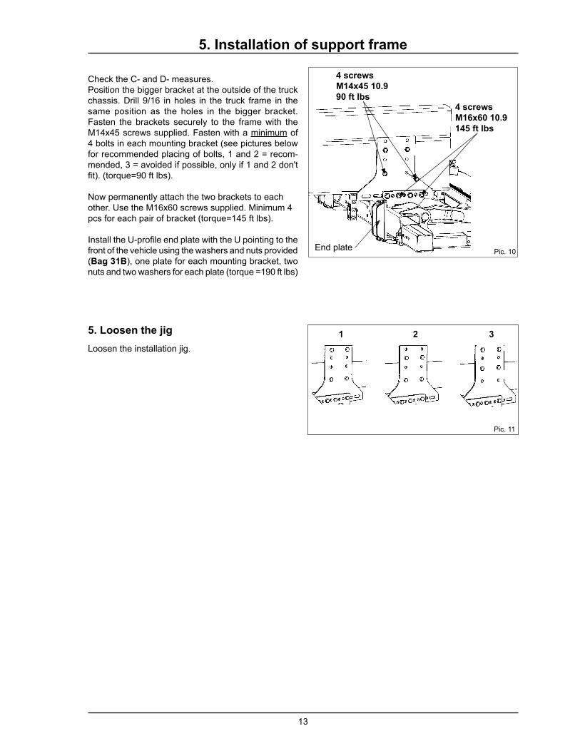
Check the C- and D- measures.Position the bigger bracket at the outside of the truck chassis. Drill 9/16 in holes in the truck frame in the same position as the holes in the bigger bracket. Fasten the brackets securely to the frame with the M14x45 screws supplied. Fasten with a minimum of 4 bolts in each mounting bracket (see pictures below for recommended placing of bolts, 1 and 2 = recom-mended, 3 = avoided if possible, only if 1 and 2 don't fi t). (torque=90 ft lbs).
Now permanently attach the two brackets to each other. Use the M16x60 screws supplied. Minimum 4 pcs for each pair of bracket (torque=145 ft lbs).
Install the U-profi le end plate with the U pointing to the front of the vehicle using the washers and nuts provided (Bag 31B), one plate for each mounting bracket, two nuts and two washers for each plate (torque =190 ft lbs)
5. Loosen the jig
Loosen the installation jig.
4 screws
M14x45 10.9
90 ft lbs4 screws
M16x60 10.9
145 ft lbs
End plate Pic. 10
Pic. 11
5. Installation of support frame
14
P3 P2T
250
9-7/8
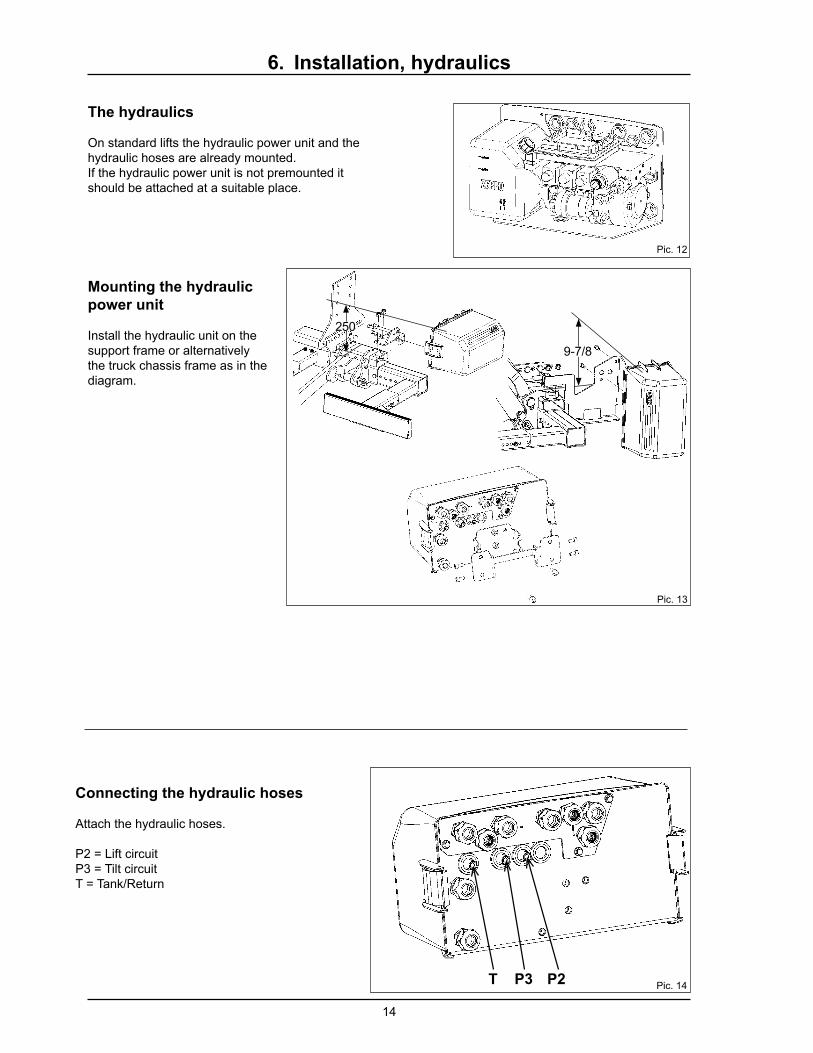
6. Installation, hydraulics
The hydraulics
On standard lifts the hydraulic power unit and the hydraulic hoses are already mounted.If the hydraulic power unit is not premounted it should be attached at a suitable place.
Connecting the hydraulic hoses
Attach the hydraulic hoses.
P2 = Lift circuitP3 = Tilt circuitT = Tank/Return
Mounting the hydraulic
power unit
Install the hydraulic unit on the support frame or alternatively the truck chassis frame as in the diagram.
Pic. 12
Pic. 13
Pic. 14
15
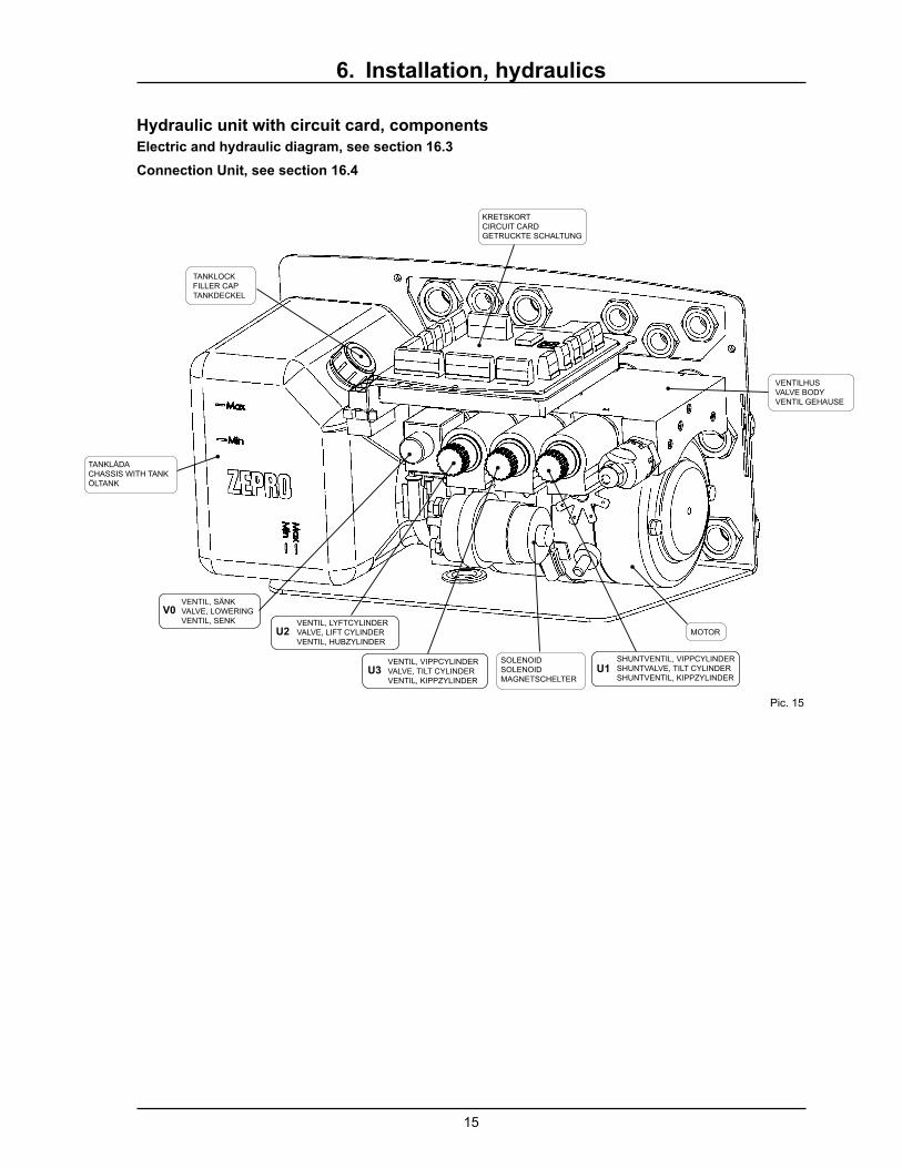
TANKLÅDACHASSIS WITH TANKÖLTANK
TANKLOCKFILLER CAPTANKDECKEL
KRETSKORTCIRCUIT CARDGETRUCKTE SCHALTUNG
VENTILHUSVALVE BODYVENTIL GEHAUSE
MOTOR
SOLENOIDSOLENOIDMAGNETSCHELTER
SHUNTVENTIL, VIPPCYLINDERSHUNTVALVE, TILT CYLINDERSHUNTVENTIL, KIPPZYLINDER
VENTIL, VIPPCYLINDERVALVE, TILT CYLINDERVENTIL, KIPPZYLINDER
U3
VENTIL, LYFTCYLINDERVALVE, LIFT CYLINDERVENTIL, HUBZYLINDER
U2
VENTIL, SÄNKVALVE, LOWERINGVENTIL, SENK
V0
U1
Hydraulic unit with circuit card, components
6. Installation, hydraulics
Electric and hydraulic diagram, see section 16.3
Connection Unit, see section 16.4
Pic. 15

16
1. Mounting control units
Install control units at suitable places, but the position of the control unit should ensure that the operator has a good view of the load, the working area and the loading area, whilst maintaining a safe distance from the risk zone between the platform and the body.
If you must lead a spiral cable up through the fl oor
you must protect it with a sheath.
Fixed control units are normally electrically heated.
The heating cable must be well earthed. Note that
12V (black) and 24 V (red) have different heating
cables.
Note that all cables must be connected from below
so that water can't get into the control units but
condensation can drain out.
7. Electrical installation
Also refer to the truck manufacturer´s electrical instructions.
Drainage pipe should be mounted
according to picture.
Recommended positions for
mounting control units.
2. Connection, control cable
The control cable is connected to the circuit card in
the connection unit (see electric schema).
Install the control current cable from the
dashboard of the truck according to the customer's
requirements. The control current switch should be
located so it is possible to be reached from the earth
10A /15A fuse between the current source and the
switch.
The control current cable is connected to a fi xed
control unit. You can fasten the cable together with
the battery cable to the hydraulic unit.
Spiral cable unit
If you have a spiral cable unit, its cable colors are
different (see electric schema).
If you want an electrically heated spiral cable unit
you can order a 5-part cable and use the blue
conductor for earthing (the white part is nearly grey).
Note that the spiral cable unit must have its fastening
plate for the wall.
Electric schema, see section 16.3
The control current cable; 10A / 15A fuse between
the current source and the switch.
Spiral cabel, 5-part: Art.nr. 21303
Fastening plate: Art.nr. 20302
Pic. 16

17
3. Connection, main power cable
Connect the main power cable to the + pole of the battery. The cable should be protected with a plastic sheath. It must not be fastened together with brake pipes or other electric cables of the truck. When passing through holes the cables must be protected with rubber bushings.
A 160 A (24 V) or 250 A (12 V) fuse is to be installed on the main power cable running from the battery compartment. This acts to protect the electrical systems from overloading and the risk of fi re. The picture below shows proper connection.
Check that the hydraulic unit is well earthed according to truck manufacturer´s instructions.
7. Electrical installation
A 160 A (24 V) or 250 A (12 V) fuse is to be installed on
the main power cable running from the battery compartment.
Note! When passing through holes the cables must be protected with rubber bushings.
Alarm for open platform
The alarm has a red lamp, which lights if the platform is not pressed against the back of the truck.The arrangement is:
*Pressure guard on the tilting system.*Cable to the dashboard.*Fuse.*Warning lamp 12 or 24 V
Testing
Switch the starter key on when the lift platform is tilted up and pressed against the back side. The warning lamp shall not light.Tilt the platform out a little from the back. The lamp shall light.Switch the start key off. The lamp turns off.Switch the starter key on and the lamp shall light.Shut the platform very well and the lamp turns off.
**Note! The fuse should be placed on a well
protected place and as near as possible to the
battery.
Pic. 17
Pic. 18

18
7. Electrical installation
Connection of non-original components on zepro
tail lifts
It has always been forbidden to connect foreign equipment (both electric and hydraulic) on allZepro tail lifts. Using non-original components can affect tail lift safety. If it's really important for you to make such installations please check with the vehicle manufacturers installation instructions and use the trucks capabilities.

19
F
When the platform is installed you should test to run the lift carefully. Check the platform position at the rear frame.
1. Attaching the Platform
Install the platform on the lift arms and the tilt cylin-ders according to pictures. Use the pivot bolts and locking screws supplied.
The platforms overlap (F) is dependent on the type of platform. Please note the values below which are particularly relevant when installing a rubber seal on the body at the top of the platform.
Type Flat 1-3/16
F (in) 2-15/16Body fl oor
8. Mounting, platform and sealing system
NOTE! To get the full opening speed a tilt angle
sensor should be installed according to the
pictures. Note! It's is important that the cable
is turned in the right direction according to
pictures.
Flat 1-3/16 in platform:
Place the angle sensor on the inside of platform
bracket, pic. 20-1.
Conical platform
Place the angle sensor on the outside of platform
bracket, pic. 20-2.
Pic. 19
Pic. 20-1
Pic. 21
Pic. 20-2

20
1-1/2 - 1-9/16
*m
in -
max
4 in
2. Mounting sealing system
Check the space between body fl oor and platform.
The space should be 1-1/2 - 1-9/16 in.
Sealing system (vertical)
Install the profi les for the vertical sealing strips. Note
the position of the lock ears.
The profi les can be fastened with screws, rivets or
welding. The rubber strips are installed after the lock
ears.
The rubber strips are locked by pressing the rails
together.
If upper seal must be installed you must mitre 45
degrees to the vertical profi les for a good fi t.
Sealing system (horizontal)
Install the horizontal aluminium or steel guide bar.
Self-tapping screws delivered. Drill 9/32" holes. Mitre
the rubber against the side seal.
Test run the lift carefully and control its position in re-
lation the to horizontal guide bar. Test run and check.
Raise the platform carefully to vertical position Check
the fi t against the horizontal guide bar.
Transport lock
For CE marked lifts with 2200 lb max lifting capacity and over, ZEPRO/Waltco provides platforms without
transport lock. For other lifts transport locks are installed on the platforms right side.
Electric safety valves can serve as transport locks for platforms. The lock opens automatically when the
down function of the control unit is activated.
The valves are one-way valves which allow oil to fl ow into the cylinders but not out from them unless current
has been supplied to them via the lowering valves. The platform is hence hydraulically locked under
transport.
8. Mounting, platform and sealing system
3. Mounting armstops
Mount armstop* as high as possible on the lift arms,
in the position that the adjustment-screws get a good
surface contact with the truck's rear frame.
If necessary install a stop bar to make a better
contact point for the armstop.
Adjust the two screws so they meet the rear frame/
stop bar at the same time.
If the truck has a mounting bracket kit, see the
separate instructions for this kit regarding the
armstop installation.
NOTE! No welding is allowed on the lift arm!!
For trucks with mounting brackets, see separate installation instructions. See list, section 3.
*the armstop is an optional extra-if required
please order art. nr. 53869 for Z 100 models
Pic. 22
Pic. 23
Pic. 24
21
A
Max 2 in
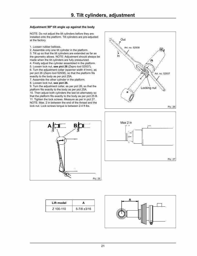
9. Tilt cylinders, adjustment
Adjustment 90º tilt angle up against the body
NOTE: Do not adjust the tilt cylinders before they are installed onto the platform. Tilt cylinders are pre-adjusted at the factory.
1. Loosen rubber bellows.2. Assemble only one tilt cylinder in the platform.3. Tilt up so that the tilt cylinders are extended as far as the geometry allows. NOTE: Adjustment should always be made when the tilt cylinders are fully pressurized. 4. Firstly adjust the cylinder assembled in the platform.5. Loosen lock nut, see pict 26 (Zepro tool 52937).6. Turn the adjustment collar (spanner width 41mm), as per pict 26 (Zepro tool 52938), so that the platform fi ts exactly to the body as per pict 25A.7. Assemble the other cylinder in the platform.8. Loosen lock nut, see pict 26.
9. Turn the adjustment collar, as per pict 26, so that the platform fi ts exactly to the body as per pict 25A.10. Then adjust both cylinders the last bit alternately so that the platform fi ts exactly to the body as per pict 25 B.11. Tighten the lock screws. Measure as per in pict 27. NOTE: Max. 2 in between the end of the thread and the lock nut. Lock screws torque is between 2-4 ft lbs.
Locking nut
Out
In
Art. no. 52937
Art. no. 52938
Pic. 26
Pic. 25
Pic. 27
Lift model A
Z 100-110 5-7/8 ±3/16

22
5
4
2
3
2
3
5
4
Ring
Lock nut
Adjustable collar
Lock screw
Adjustment of tilt down angle.
NOTE! To have the taillift to comply with CE requirements and be safe, it is required that tilt down angle is adjusted to a maximum of 10º.NOTE! It is necessary to fi rst adjustment the 90º tilt angle up against the body before adjusting tilt down angle.
1. Run the lift up so that the lift is at the fl oor level, see pict 28.
2. Loosen the ring's lock screw (2). Screw the ring out in the direction of the platform (3). See pict 29.
3. Tilt down the platform to maximum 10 degrees under horizontal. As per pict 28.
4. Adjust the ring to the top of the cylinder (4).
5. Tighten the lock screw in the ring (5). See pict 30.
Reassemble rubber bellows.Lock screws torque is between 2-4 ft lbs.Note! Both cylinders tilt down angle must be adjusted equally, otherwise there is the risk that the cylinders will break.Test run all functions.
9. Tilt cylinders, adjustment
Pic. 28
Pic. 29
Pic. 30
Pic. 31

23
Bleeding the cylindersFor all lift cylinder models.Fully lower the platform a few times. You may have to lift the truck (eg. hang over a curb) to fully lower the platform.
Concerning tilt cylinder modelsTilt cylinders can be purged of air by closing the platform up against the vehicle body and then opening and tilting all the way down.
9. Mounting cylinders, adjustment, other
3. Side adjustable
2. Immovable
1. Length adjustable
Mounting 3-part bumper bar
The bumper bar contains four length adjustable (1) brackets, two side adjustable (3), two immovable (2) brackets and three aluminium profi les.
Mount the bumper bar according to the pictures. Check that it is positioned within approved dimensions. Max 21-5/8 in between bar and ground when the vehicle is unloaded (25-9/16 in for uplifted bogey). Max 9-1/8 in horizontal distance from axis through centre point of platform bolts to bar. See pictures page 23.
The lateral distance between bumper bar and moving parts of the tail lift must not exceed 1 in. The bumper bar must, in each case, have an effective surface area of at least 54.3in2, see picture
Mount each length adjustable bracket with two bolts M10x100 (8.8), each immovable bracket with two bolts M10x70 (8.8) and each side adjustable bracket with two different bolts one M12x120 and one M8 taptite (8.8) see pic. above. The taptite M8 bolt is used in order to freeze the side adjustable brackets. Tighten M10 bolts to 37 ft lbs, M12 bolts to 50 ft lbs and taptite M8 15 ft lbs
M8 taptite
Pic. 32

24
max 21-9/16 in
max 3-15/16 in
max 9-1/8 in
M8x20 (8.8) 18 ft lbsmin 54 sq in
max 1 inmax 1 in
Standard, bumper bar
10. Mounting, other
Mount the aluminium profi les with 2 bolts M8x20 (8.8) each, tighten to 18 ft lbs. Put the bolt heads into the aluminium profi le, and then position the profi les onto the brackets.
Pic. 34
Pic. 33
Pic. 35
Pic. 36
If the tail lift is equipped with auto tilt must an angle switch be installed at the lift arm.

25
min 1-9/16 in
10º
10º
Repainting
NOTE: If the cylinders are to be repainted, ensure that the cylinder push rod and cover are not painted (this can damage the seals/gaskets). This also applies to rubber bellows if they exists!
Replace the transport plug
During installation the oil tank transport plug should be
removed and replaced
Hydraulic hoses or cables must not be painted, the
paint's solvent can damage the hose's/cables rubber
compound and can adversely affect durability
Moveable parts - free movement
When the fi nal post-installation testing is carried
out, it is important that there is suffi cient clearance
between the cylinders working envelopes and all
fi xed points. During lift operation and cylinder move-
ment there is a risk for confl ict with the sub frame,
truck frame, number plate, lamp holders and even
the mounting brackets when the overhang is very
limited (due to lift arm angle). Hence it is important to
thoroughly check all of these points on both sides.
The fi nal test is performed with the platform at fl oor
height tilted down 10° from the horizontal. The cylin-
ders must have a minimum clearance of 1-9/16 in to
all fi xed points from this position.
11. Important information
Pic. 37
Pic. 38
Pic. 40
Pic 39
Note! The platform must not be tilted down more
than max 10° below the horizontal.

26
We suggest that you stick the yellow/black warning tape along the side edge of the platform to make it more clearly visible when in the horizontal position.
12. Markings, decals
The name plate is installed on the support frame of the tail lift and contains the following information:
-Lift type -Maximum permitted load in kg -Serial number -Year of manufacture -Address and tel. no. of the manufacturer -Country of manufacture -ECE type no. for bumper bar certifi cate (RUPD) and EMC
There is also a similar name plate in the form of a decal which is to be affi xed to the cabin’s door frame to ensure correct product identifi cation.
A "danger area" decal is also to be placed on the
platform warning drivers who are parking cars
behind the vehicle that 5m are necessary to allow for
platform opening and suffi cient manoeuvring space
for loading and unloading goods.
The loading diagram plates should be placed near
the control unit and in a clearly visible position on
the platform. The plate clearly indicates the nominal
loading and the diagram shows the maximum
permitted loading at different positions on the
platform.
Install the warning fl ags with refl ecting strips, as
close to the top and to the side of the platform as
possible, however, ensure that the fl ags will not
detach when the platform reaches the ground.
Crimp the ends of the fl ag profi les
so that the fl ags stay in position.
An operating instructions decal should be placed
next to the main control unit.
A danger zone decal, warning of the danger area
between the platform and the vehicle bed is to be
affi xed on the inside of the vehicle body near to the
spiral cable control, if installed.
Pic. 41
Pic. 43
Pic. 42

27
207 ft lbs
145 ft lbs
37 ft lbs
18 ft lbs
50 ft lbs &
15 ft lbs
18 ft lbs
190 ft lbs
13. Torque values

28
1
2
5
6
48
7
9
10
11
12
3
14. Maintenance, lubrication chart
Grease all bearings and platform locks with LE lubricant 4622 or equivalent.
Greasing at least 8 times / year
1. Right tilt cylinder, lower bearing.2. Right lift cylinder, lower bearing.3. Lift arm right side, lower bearing.4. Left liftc ylinder, lower bearing.5. Left tilt cylinder, lower bearing.6. Lift arm left side, lower bearing.7. Left tilt cylinder, upper bearing.8. Right tilt cylinder, upper bearing.9. Lift arm right side, upper bearing.10. Right lift cylinder, upper bearing.11. Left lift cylinder, upper bearing.12. Lift arm left side, upper bearing.
The hydraulic unit tank is fi lled with a mineral based hydraulic oil (art.no 21963 for 1 litre.) or a biodegradable synthetic oil (art.no 22235 for 1 litre). There is a sticker on the hydraulic unit indicating which type of oil is in the tank.
29
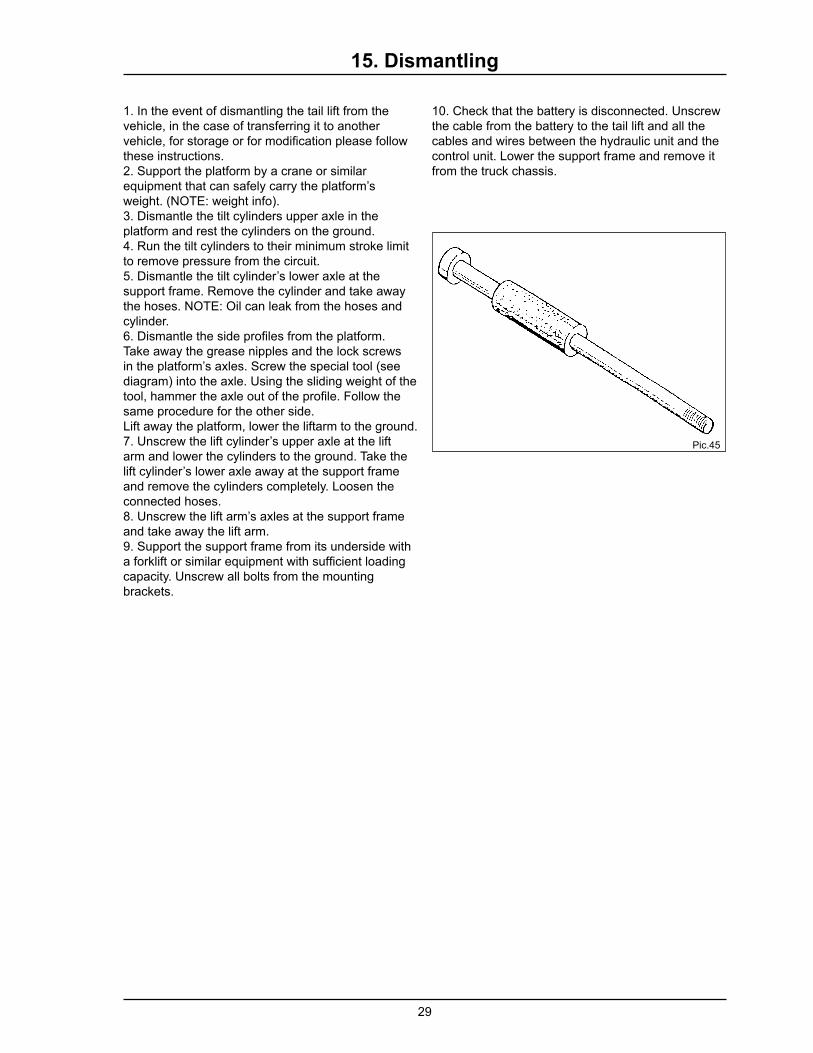
15. Dismantling
10. Check that the battery is disconnected. Unscrew the cable from the battery to the tail lift and all the cables and wires between the hydraulic unit and the control unit. Lower the support frame and remove it from the truck chassis.
1. In the event of dismantling the tail lift from the vehicle, in the case of transferring it to another vehicle, for storage or for modifi cation please follow these instructions.2. Support the platform by a crane or similar equipment that can safely carry the platform’s weight. (NOTE: weight info).3. Dismantle the tilt cylinders upper axle in the platform and rest the cylinders on the ground.4. Run the tilt cylinders to their minimum stroke limit to remove pressure from the circuit.5. Dismantle the tilt cylinder’s lower axle at the support frame. Remove the cylinder and take away the hoses. NOTE: Oil can leak from the hoses and cylinder.6. Dismantle the side profi les from the platform. Take away the grease nipples and the lock screws in the platform’s axles. Screw the special tool (see diagram) into the axle. Using the sliding weight of the tool, hammer the axle out of the profi le. Follow the same procedure for the other side.Lift away the platform, lower the liftarm to the ground.7. Unscrew the lift cylinder’s upper axle at the lift arm and lower the cylinders to the ground. Take the lift cylinder’s lower axle away at the support frame and remove the cylinders completely. Loosen the connected hoses.8. Unscrew the lift arm’s axles at the support frame and take away the lift arm.9. Support the support frame from its underside with a forklift or similar equipment with suffi cient loading capacity. Unscrew all bolts from the mounting brackets.
Pic.45

30
1. Max power consumption, Loading diagram .............................................. 31
2. Dimensions for installation ........................................................................ 32
3. Electric and hydraulic diagram ................................................................. 35
4. Connection unit ........................................................................................ 38
16. Tables, diagrams
31
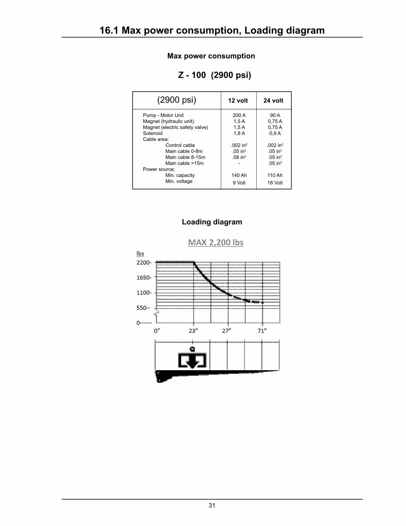
Z - 100 (2900 psi)
12 volt 24 volt
200 A1,5 A1,5 A1,8 A
.002 in2
.05 in2
.08 in2
-
140 Ah
9 Volt
90 A0,75 A0,75 A0,9 A
.002 in2
.05 in2
.05 in2
.05 in2
110 Ah
18 Volt
(2900 psi)
16.1 Max power consumption, Loading diagram
Loading diagram
Max power consumption
Pump - Motor UnitMagnet (hydraulic unit)Magnet (electric safety valve)SolenoidCable area: Control cable Main cable 0-8m Main cable 8-15m Main cable >15mPower source: Min. capacity Min. voltage

32
6-¾
C
1-9/16D
maxmin
A
max21-¾
43 maxH
C A D
21-¾ 5-¾ 17-¾
19-¾ 5-¼ 20
17-¾ 4-¾ 22
15-¾ 4-½ 23-½
13-¾ 4-¼ 24-¾
11-¾ 4 25-¾
For models with lifting height 43"
Z-100-110
16.2 Dimensions for installation
Lifting height 43"

33
Z-100
44.84.9
A max
4.9
8-3/4
7-1/2
3
2-3/1644.84.9
A max
4.9
57-1/2
min 29 - max 39
7-15/16
9-1
/2
27-1/2
min 20-3/16 - max 24-1/8
57-1/2
min 29-½ - 34 max
min 20-3/16 - max 24-1/8
16.2 Dimensions for installation
min 74-3/4 - max 96 (body width 74-3/4 - 102)
min 74-3/4 - max 96 (body width 74-3/4 - 102)

34
Z-100
11
22
33
44
55
66
Denna ritning är Z-Lyftens egendom och skyddad enligt internationellt gällande lag för copyrightoch får ej utan Z-Lyftens skriftliga medgivande kopieras, delges eller obehörigen användas.
This drawing is property of Z-Lyften Produktion AB and is loaned subject to return upon demand. It is notto be reproduced or used directly or indirectly in any way detrimental to the interest of Z-Lyften Produktion AB.
Re
v./R
ev.T
ag
Da
tum
/D
ate
Än
drin
g/
Re
v. nu
mb
er
Infö
rd a
v/R
evise
d b
yK
on
trol./
Ch
ecke
dA
pp
rove
d
A2
00
9-0
1-0
95
98
3M
BM
W
Dä
r an
na
t ej a
ng
es / D
raw
ing
inte
rpre
tatio
n u
nle
ss oth
erw
ise sp
ecifie
d.
All m
ea
sure
s inte
nd
s finish
ed
pro
du
ctA
lla m
ått a
vser fä
rdig
pro
du
kt.B
en
äm
nin
g/T
itle
Ma
teria
l
Dim
en
sion
Da
tum
/ Da
te
Vikt/W
eig
h(kg
)
Ska
la/S
cale
Ko
nstr./D
esig
ne
rK
on
tr./Ch
ecke
d b
yG
od
k./Ap
pro
ved
by
Artike
lnr./S
tock n
r.
Ritn
ing
snr./D
raw
ing
nr.
Bla
d/S
he
et
Fo
rma
t/Size
Re
vision
Fö
r de
nn
a ritn
ing
gä
ller
IS0
tole
ran
ser S
MS
ritreg
ler
To
lera
nse
r/T
ole
ran
ce:
Ytjä
mn
he
t/S
urfa
ce fin
ish:
Sve
ts/We
ldin
g:
1/1
Rita
d/D
raw
n
A H
IAB
bra
nd - p
art o
f Carg
ote
c Corp
ora
tion
Sa
mm
./Use
d o
n:
B2
01
3-0
2-2
26
75
5M
E-
C2
01
3-0
3-1
96
77
6T
H-
D2
01
4-0
4-0
36
95
4T
H1
76
E2
01
4-0
6-2
47
02
5T
H2
07
Ctrl 4
Spira
l
Ctrl 3
Radio
Ctrl 2 C
trl 1
Control Power
Senso
r Pow
er
Ground
INO
UT
Ai 1
Ai 2
Di 1
Di 2
Di 3
Di 4
Di 5
Di 6
PA
-
PA
+
CS
PW
R
CS
+
BEC2H
1
BEC2H
2BECLo
ck
BECLo
ck
U7
U6
U5
U4
U3
U5
U4
U2
U1
U0
Ctrl 6Out
In
Spk-
Spk+
I-
I+
CR
CT
Ctrl 5
Indica
tion
Se a
ppendix in
insta
llatio
n m
anual
Outp
uts
Sensors
F2
01
6-0
2-2
97
23
1M
B-
G2
01
6-0
5-3
07
28
4M
B-
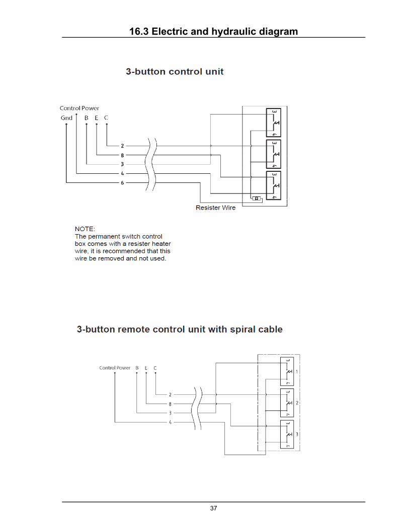
16.3 Electric and hydraulic diagram

35
11
22
33
44
55
66
Denna ritning är Z-Lyftens egendom och skyddad enligt internationellt gällande lag för copyrightoch får ej utan Z-Lyftens skriftliga medgivande kopieras, delges eller obehörigen användas.
This drawing is property of Z-Lyften Produktion AB and is loaned subject to return upon demand. It is notto be reproduced or used directly or indirectly in any way detrimental to the interest of Z-Lyften Produktion AB.
Dä
r an
na
t ej a
ng
es / D
raw
ing
inte
rpre
tatio
n u
nle
ss oth
erw
ise sp
ecifie
d.
All m
ea
sure
s inte
nd
s finish
ed
pro
du
ctA
lla m
ått a
vser fä
rdig
pro
du
kt.B
en
äm
nin
g/T
itle
Ma
teria
l
Dim
en
sion
Da
tum
/ Da
te
Vikt/W
eig
h(kg
)
Ska
la/S
cale
Ko
nstr./D
esig
ne
rK
on
tr./Ch
ecke
d b
yG
od
k./Ap
pro
ved
by
Artike
lnr./S
tock n
r.
Ritn
ing
snr./D
raw
ing
nr.
Bla
d/S
he
et
Fo
rma
t/Size
Re
vision
Fö
r de
nn
a ritn
ing
gä
ller
IS0
tole
ran
ser S
MS
ritreg
ler
To
lera
nse
r/T
ole
ran
ce:
Ytjä
mn
he
t/S
urfa
ce fin
ish:
Sve
ts/We
ldin
g:
1/1
Rita
d/D
raw
n
A H
IAB
bra
nd
- pa
rt of C
arg
ote
c Co
rpo
ratio
n
Sa
mm
./Use
d o
n:
Re
v./R
ev.T
ag
Da
tum
/D
ate
Än
drin
g/
Re
v. nu
mb
er
Infö
rd a
v/R
evise
d b
yK
on
trol./
Ch
ecke
dG
od
k./A
pp
rove
d
A2009-0
1-0
95983
MB
MW
CL
B2013-0
2-2
26755
ME
-C
L
C2013-0
3-1
96776
TH
-C
L
D2014-0
4-0
36954
TH
176C
L
E2014-0
6-2
47025
TH
207
PL
Ctrl 4
Sp
iral
Ctrl 3
Ra
dio
Ctrl 2 C
trl 1
Control Power
Se
nso
r Po
we
r
Ground
INO
UT
Ai 1
Ai 2
Di 1
Di 2
Di 3
Di 4
Di 5
Di 6
PA
-
PA
+
CS
PW
R
CS
+
BEC2H
1
BEC2H
2BECLock
BECLock
U7
U6
U5
U4
U3
U5
U4
U2
U1
U0
Ctrl 6
Out
InSpk-
Spk+
I-
I+
CR
CT
Ctrl 5
Ind
icatio
nS
e a
ppe
ndix in
insta
llatio
n m
anu
al
Ou
tpu
ts
Sensors
F2016-0
2-2
97231
MB
-P
S
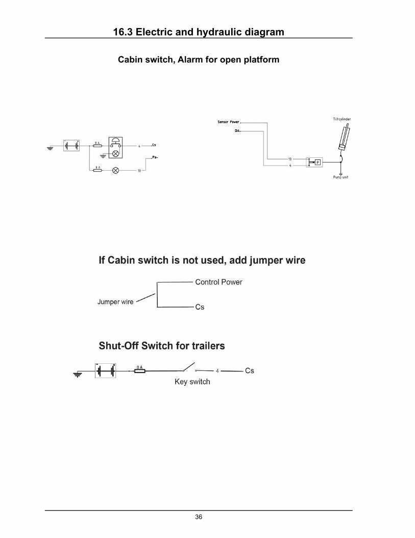
16.3 Electric and hydraulic diagram
Z-100, with hydraulic auto-tilt
36
Cabin switch, Alarm for open platform
16.3 Electric and hydraulic diagram
37
16.3 Electric and hydraulic diagram

38
Platform Lights
Connect the platform lights as shown below. Mount the light sensor as pictured.
From closed to 45 degrees, the warning lights should be turned off.
From 45 degrees to open, the warning lights should be turned on.
39
16.4 Connection unit
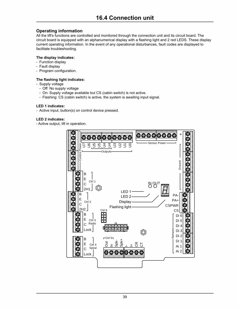
Operating informationAll the lift's functions are controlled and monitored through the connection unit and its circuit board. The circuit board is equipped with an alphanumerical display with a fl ashing light and 2 red LEDS. These display
current operating information. In the event of any operational disturbances, fault codes are displayed to
facilitate troubleshooting.
The display indicates:
- Function display
- Fault display
- Program confi guration.
The fl ashing light indicates:
- Supply voltage
- Off: No supply voltage
- On: Supply voltage available but CS (cabin switch) is not active.
- Flashing: CS (cabin switch) is active, the system is awaiting input signal.
LED 1 indicates:
- Active input, button(s) on control device pressed.
LED 2 indicates:
- Active output, lift in operation.
Ctrl 4Spiral
Ctrl 3Radio
Ctrl 2
Ctrl 1
Co
ntr
ol P
ow
er Sensor Power
Gro
un
d
IN OUT
Ai 2
Ai 1
Di 1
Di 2
Di 3
Di 4
Di 5
Di 6
PA-
PA+
CSPWR
CS
+
B
E
C
2H1
B
E
C
2H2
B
E
C
Lock
B
E
C
Lock
U7
U6
U5
U4
U3
U5
U4
U2
U1
U0
Ctrl 6
Out
In Spk-
Spk+
I- I+ CR
CT
Ctrl 5
Outputs
Se
nso
rs
Display
Flashing light
LED 2
LED 1
40
Information codes
Codes are shown on the display in a sequence. First a letter for identifi cation of information, followed by fi gures or segments for further information and then ending with a pause:
When the CS (cabin switch) is switched on, the current program confi guration (P) is displayed fi rst, followed by confi guration number. The number of volts detected is then displayed and, after this, the current software version (J), followed by version number.
As long as no control device is used, a scrolling sequence is then displayed, with sensor indication (C), followed by 0-6 segments showing which sensors have a signal.
When a control device is used, the control device being used (1-7) is displayed, followed by which button has been pressed, segments B, C, E or X (X symbolises the 4th button on the respective control device (2h1 for fi xed control device 1, 2h2 for fi xed control device 2, lock knob for radio control device and coil control device).
The control devices are symbolised by the fi gures 1-7.
1. Fixed control device 1, including two-hand button 2h12. Fixed control device 2, including two-hand button 2h23. Radio control device, External4. Coil control device5. Truck slider control device6. Radio control device, internal module7. CS (cabin switch)
Once a button has been released, the control system for the current control device is locked for a while to ensure that no other person operates the lift from another control device. During the period the control system is locked for the current control device, its number (1-7) will fl ash on the display. This primarily applies to radio and coil control devices as control devices have such a short locking period that there is hardly time to see the indication.
Coil and radio control devices can be equipped with a locking function. Once the control device has been used, the control system is locked for the current control device until it is unlocked manually from the respective control device's deactivation button. With some confi gurations, however, the coil control device can, for safety reasons, always tilt the platform down in the event of the operator getting shut inside.
16.4 Connection unit

41
Information codes
Identifi cation Code 1Code
2
Code
3Information Other
P(Program
confi guration)
00–99 Cancelled confi guration
- Dividers
12/24 Number of volts detected
J Software version
01–99Version number
1.-7 (Fixed light)Active control device
while operating
1-7Fixed light (1-7) displays active control device during operation.
B C
E X
In
Out
Segment B, C, E or X.
Segments B, C, E or X are illuminated de-pending on which button is pressed
1-7 (Flashing) The control device that the control sys-tem is locked for for a while after opera-
tion completed.1-7
Control device the control system is locked for.
This primarily applies to radio and coil con-trol devices as other control devices have such a short locking period that there is no time to see the indication.
The number will stop fl ashing when one of the current control device's buttons are pressed.
If the control card has been without voltage and receives the voltage again when the CS (cabin switch) is switched on, "7" will fl ash on the display and the control card is locked until the Off/On on the CS is operated.
CSensor indication
Segment
1-6 segments indicate sensors.
On - signal in.
Off -no signal in.
(See electrical and hydraulics diagrams for information about the location of the sensors).
Di1 Di3
Di6 Di4
Di2
Di5
Example of sequence of information codes:
Program confi guration: 01, Voltage detected: 12V, Software version: 02
16.4 Connection unit

42
Fault codes
If a fault arises, the fault code is shown in the display in the form of a letter for identifying the fault, followed by numbers and/or number segments for further information, followed by sensor indication (C) in accord-ance with the previous page.
In fault codes E, F and U, the numbers (1-9) show which control device/output the fault code refers to.
1. Fixed control device 1, including two-hand button 2h12. Fixed control device 2, including two-hand button 2h23. Radio control device, External4. Coil control device5. Truck slider control device6. Radio control device, internal module7. CS (cabin switch)8. Control Power9. Sensor Power
If the system discovers several faults, only the fault code for the fault with the highest priority will be shown automatically. The display is prioritised in the order in the table below, L/H, E, F, U and A. To see all faults, press and hold in button C on the control device. Then the system will browse through the list so that all faults the system has detected are seen.
When the CS is switched off, the system will browse through a list containing the fi ve latest faults detected before the display goes off.
Fault codes
Identifi cation Code 1 Code 2 Code 3 Information Other
L Low battery voltage
07-35 Voltage measured
HHigh battery voltage
07-35 Voltage measured
EControl device
locked
1Fixed control device (incl. two-hand button 2h1 if they are monitored)
2Fixed control device 2 (incl. two-hand button 2h2 if they are monitored)
3 Radio control device, external
4 Coil control device
5 Truck slider control device
6 Radio control device, internal module
7 CS (cabin switch)
Segment
Segments B, C, E or X will flash depending on which button signal locks the control device; a fi xed light indicates pressing the button for trou-bleshooting.
Segments B, C, E or X are illuminated depending on which button locks the control device.
B C
E X
In
Out
FOutput short-circuit-
ed/high current0-9
Which output has short-circuited/has high current.
1-7 Control device, displayed only after the respective output/function has been active.
8 Control power
9 Sensor power
Output not connect-ed/cable breakdown 0-7
Which output is not connected/ has cable breakdown.
Displayed only after the respec-tive output/function has been active.
AInternal fault 0-
Contact support if the lift does not function.
16.4 Connection unit

43
All fault codes can be reset manually by switching On/Off the CS (cabin switch). Fault codes F0-F7 and U0-U7 are reset automatically if the function in question is running (function verifi ed). Fault codes L and H are reset automatically if the battery voltage becomes correct. Fault code E is reset automatically if the control system has not received any signal from the relevant control device for 6 minutes.
Example of sequence of fault codes:
Output No. 3 short-circuited.
Supply voltage
A supply voltage of between 8.0V and 15.0V is regarded by the unit as correct for a 12V system.
A supply voltage of between 18.0V and 29.0V is regarded by the unit as correct for a 24V system.
All functions on the unit cease when the supply voltage is less than 7.0V. If the supply voltage then rises to more than 7.0V, functionality is restored.
Controller 1 (together with 2h1 on certain models) allows emergency operation of the lift at voltages down to 7V or 16V. This takes place at your own risk and only works for a limited time, after which a rest period is required.
16.4 Connection unit
44
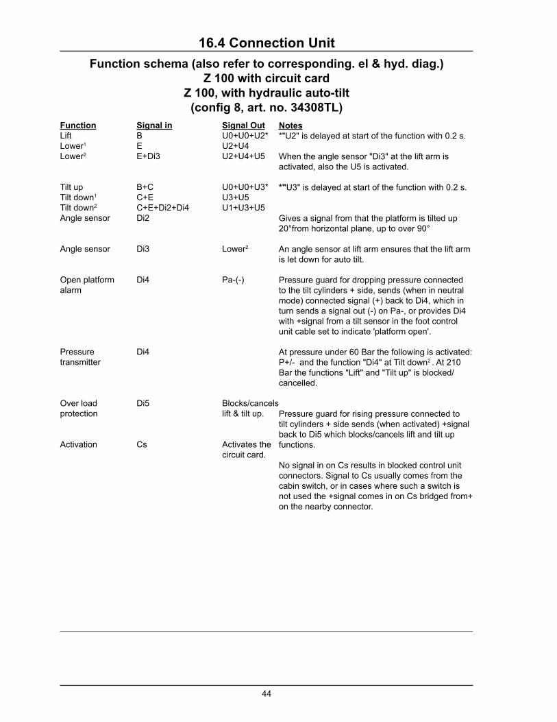
16.4 Connection Unit
Function schema (also refer to corresponding. el & hyd. diag.)
Z 100 with circuit card
Z 100, with hydraulic auto-tilt
(confi g 8, art. no. 34308TL)
Function
LiftLower1 Lower2
Tilt upTilt down1
Tilt down2
Angle sensor
Angle sensor
Open platform alarm
Pressure transmitter
Over load protection
Activation
Signal in
BEE+Di3
B+CC+EC+E+Di2+Di4Di2
Di3
Di4
Di4
Di5
Cs
Signal Out
U0+U0+U2*U2+U4U2+U4+U5
U0+U0+U3*U3+U5U1+U3+U5
Lower2
Pa-(-)
Blocks/cancels lift & tilt up.
Activates the circuit card.
Notes
*"U2" is delayed at start of the function with 0.2 s.
When the angle sensor "Di3" at the lift arm is
activated, also the U5 is activated.
*"U3" is delayed at start of the function with 0.2 s.
Gives a signal from that the platform is tilted up
20°from horizontal plane, up to over 90°
An angle sensor at lift arm ensures that the lift arm
is let down for auto tilt.
Pressure guard for dropping pressure connected
to the tilt cylinders + side, sends (when in neutral
mode) connected signal (+) back to Di4, which in
turn sends a signal out (-) on Pa-, or provides Di4
with +signal from a tilt sensor in the foot control
unit cable set to indicate 'platform open'.
At pressure under 60 Bar the following is activated:
P+/- and the function "Di4" at Tilt down2 . At 210
Bar the functions "Lift" and "Tilt up" is blocked/
cancelled.
Pressure guard for rising pressure connected to
tilt cylinders + side sends (when activated) +signal
back to Di5 which blocks/cancels lift and tilt up
functions.
No signal in on Cs results in blocked control unit
connectors. Signal to Cs usually comes from the
cabin switch, or in cases where such a switch is
not used the +signal comes in on Cs bridged from+
on the nearby connector.

45
IMPORTANT
WARNING Improper operation and maintenance of this liftgate could result in severe personal injury or death.
Read and understand the contents of liftgate Owner’s manual and all warning and operation decals before operating and/or performing maintenance on this liftgate.
For SAFETY information on this liftgate see Chapter 1 of Owner’s manual
80101666 EO7714
Rev 01