installation manual vhf radiotelephone fm-8800d/8800s · 2020-06-12 · d: duplex fm-8800d s:...
TRANSCRIPT

www.furuno.co.jp
All brand and product names are trademarks, registered trademarks or service marks of their respective holders.
Installation Manual VHF RADIOTELEPHONE
FM-8800D/8800S
System Configuration .......................................................................................................................... ii
Equipment Lists ................................................................................................................................ iii
1. Mounting ..................................................................................................................................... 1-1
2. Connections ................................................................................................................................ 2-1
3. Assembling console kit ............................................................................................................... 3-1
Packing Lists ................................................................................................................................... A-1
Outline Drawings ............................................................................................................................. D-1
Interconnection Diagrams ................................................................................................................ S-1

The paper used in this manualis elemental chlorine free.
・FURUNO Authorized Distributor/Dealer
9-52 Ashihara-cho,Nishinomiya, 662-8580, JAPAN
Telephone : +81-(0)798-65-2111
Fax : +81-(0)798-65-4200
A : SEP 2004.Printed in JapanAll rights reserved.
J : MAY 27, 2010Pub. No. IME-56420-J
*00014993218**00014993218*(TOMA ) FM-8800D/S*00014993218**00014993218** 0 0 0 1 4 9 9 3 2 1 8 *

i
SAFETY INSTRUCTIONS
WARNINGHazardous voltage. Can shock, burn or causeserious injury.
Do not work inside the equip-ment unless totally familiarwith electrical circuits.
Turn off the power at the mains switch-board before beginning the installation.Post a warning sign near the switch-board to indicate that power should not be applied while the equipment is beinginstalled.
Electrical shock, serious injury or fire canresult if the power is not turned off or isapplied while the equipment is beinginstalled.
Attach securely protective earth to the ship's body.
The protective earth (grounding) is required to the AC/DC power supply unit to prevent electrical shock.
Confirm that the power supply voltageis compatible with the voltage ratingof the equipment.
Connection to the wrong power supply can cause fire or equipment damage. The voltage rating appears on the labelat the rear of the display unit.
Observe the compass safe distance to prevent deviation of a magneticcompass.
Standardcompass
Steeringcompass
1.45 m
CAUTION
FM-8800S 0.90 m
1.45 mFM-8800D 0.95 m
0.85 mIF-8810 0.55 m
0.75 mIF-8820 0.50 m
1.50 mHS-2003 0.95 m
0.40 mHS-8800 0.30 m
1.20 mRB-8800
0.80 m
1.50 mRB-8810
1.00 m
(W/HS-8800)
(W/HS-8800)
0.90 mPR-240 0.60 m
Do not approach the antennacloser than 0.9 m (MPE by FCC) when it is transmitting.
(MPE: Minimum Permissible Exposure)
The antenna emits radio waveswhich can be harmful to thehuman body.
FM-8800S
RF power densityon antenna aperture
Distance
100 W/m 2 0.11 m
10 W/m 2 0.33 m
FM-8800D
2 W/m 2 0.9 m
0.11 m
Descriptionrequired by
IEC 60945
IEC 60945MPE by FCC
IEC 60945
IEC 60945
MPE by FCC
0.33 m
0.9 m
100 W/m 2
10 W/m 2
2 W/m 2
1.55 mRB-8810-W(W/HS-8810-W)
1.00 m

ii
SYSTEM CONFIGURATION
Transceiver Unit
FM-8800DFM-8800S
HandsetHS-2003
VHFAntenna
CH 70 RX Antenna
AC/DCPower SupplyUnitPR-240
Category of units
Antenna
All other units
Exposed to weather
Protected from weather
Category
Radio Battery24 VDC
24 VDC
JunctionBox*IF-8810
PrinterPP-510PP-8800/A
ExternalSpeakerSEM-21Q
Wing handset
T/R AF output for VDR
MAX 2 sets
IEC61162-1 input
DSC information output
Unit
: Standard
: Optional
External alarmRemote stationRB-8800/8810RB-8810-W
DMC I/FIF-8820
MAX 4 sets
RB-8800/8810RB-8810-W
*: Option for FM-8800S/D-N
PrinterIF+UTP-80FKIF+UTP-58E
VHF consoleRC-8800
ALARM UNITIC-350

iii
EQUIPMENT LISTS
Standard Supply Name Type Qty Code No. Remarks
FM-8800D-E-A FM-8800D-E-NFM-8800D-F-A FM-8800D-F-N FM-8800S-E-A FM-8800S-E-N FM-8800S-F-A FM-8800S-F-N FM-8800S-R-A
1 Transceiver Unit
FM-8800S-R-N
1 —
D: Duplex S: Simplex E: With handset
HS-2003 F: With microphone DM-2003-F A: With IF-8810 N: No IF-8810 R: Russian version
FP05-05700 000-054-228
For E-type Handset HS-2003, Hanger FP05-05510, Others FP05-05511
2 Accessories*
FP05-05710
1
000-054-156 For F-type Microphone DM-2003-F
3 Junction Box IF-8810 1 — For A-type
4 Installation Materials* CP05-09900 1 000-054-227 Power cable 05S9371,
CP05-09901 5 Spare Parts* SP05-05501 1 005-377-820
Standard Supply for VHF Console
Name Type Qty Code No. Remarks 1 VHF Console RC-8800-SN
RC-8800-DN RC-8800-SA RC-8800-DA RC-8800-SB RC-8800-DB
1 — D: Duplex FM-8800D S: Simplex DM-8800S N: No printer A: With printer UTP-80FK B: With printer UTP-58E
2 Installation Masteries* CP05-10201 1 005-371-850
FP05-05800 000-054-372 Handset HS-2003 & Handset hanger FP05-05510 3 Accessories*
FP05-05810 1
000-010-428 HS-2003, FP05-05510, Thermal paper TP058-30CL
*: See lists at the end of this manual.

EQUIPMENT LISTS
iv
Optional Equipment Name Type Code No. Remarks Flush Mount Kit OP05-102 000-054-120 Junction Box IF-8810 — W/ Screw 5x20 4 pcs. DMC Interface IF-8820 — No use for Russian version
RB-8800-15 (W/ 1.5 m Cable) RB-8800-20 (W/ 2 m Cable)
— ·FP05-05701*, ·Handset HS-8800, ·Hanger W/DIST. button HG-8800
RB-8810-15 (W/ 1.5 m Cable) RB-8810-20 (W/ 2 m Cable)
— ·FP05-05511*, ·Handset HS-8800, ·Hanger HG-8810
Remote Station
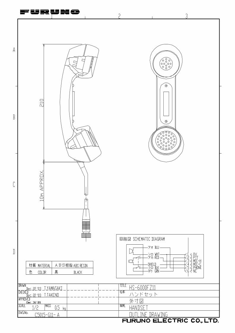
RB-8810-W-15 — W/ HS-8800-W-15 HS-8800-15 000-054-230 W/ 1.5 m Cable HS-8800-20 000-054-171 W/ 2 m Cable HS-8800-W-15 000-054-287 Waterproof HS-2003-15 000-054-223 W/ Cable 1.5 m HS-2003-20 000-054-390 W/ Cable 2.0 m HS-2003-50S 000-054-391 W/ Straight cable 5.0 m HS-6000FZ11 000-135-072
Handset
FP05-05700 000-010-246 HS-2003-15 & Hanger HG-8800 000-054-229 For HS-8800 HG-8810 000-054-231 For HS-8800 FP05-05510 005-951-790 For HS-2003 Handset Hanger
AP-102 000-580-019 For HS-6000FZ11 Loudspeaker SEM-21Q 000-144-917
Dynamic Mic. Set OP05-57 000-045-775Handset HS-6000FZ5, Receptacle RDB-VHF(B), Hanger AP-102
Carbon Mic. Set OP05-58 000-045-776Handset HS-6000FZ6, Receptacle RDB-VHF, Hanger AP-102
Handset set OP05-42 000-045-778Handset HS-6000FZ11, Receptacle RDB-VHF(B), Hanger AP-102
Mic. Receptacle Box RBD-VHF (B) 000-056-094
Microphone DM-2003-F 005-377-760 For transceiver unit only (not RB-8800), **
Printer PP-510 — Printer Interface IF-8500 — AC-DC Power Supply PR-240 —
AP05-00800 000-057-721
Whip antenna FAB-151D, Mounting plate 4-310071, Coax. Cable 5D-2V 10m, Connector M-P-5 2 PCS
AP05-00810 000-057-722Whip antenna RA106, Mounting plate RA115, Coax. Cable 05S9104 5m
AP05-00900 000-057-739 Whip antenna 396-1, Mounting plate 4187
Antenna Material
AP05-01000 000-054-123Whip antenna FAB-151D, Mounting plate 4-310071, Connector M-P-7 2 PCS
*: See lists at the end of this manual **: Microphone DM-2003-F can be connected to transceiver unit instead of handset HS-2003. However,
in this case, any remote station is disabled.

EQUIPMENT LISTS
v
Name Type Code No. Remarks
AP05-01100 000-054-224 Whip antenna 150M-W2VN, Coax. Cable 5D-2V 10m, Connector M-P-5 2 PCS
AP05-01200 000-054-232
Whip antenna FAB-151D, Mounting plate 4-310071, Coax. Cable 5D-2V 10m, Connector M-P-5 & M-P-7
Antenna Material
AP05-01210 000-054-233
Whip antenna FAB-151D, Mounting plate 4-310071, Coax. Cable 5D-2V 20m, Connector M-P-5 & M-P-7
05S0309 *10M* 000-106-043 10m 05S0309 *20M* 000-106-044 20m 05S0309 *30M* 000-106-046 30m 05S0309 *40M* 000-106-047 40m
Signal Cable
05S0309 *50M* 000-106-048 50m 000-111-680 5m 000-120-792 10m 000-120-793 15m 000-120-794 20m
Twisted Cable CO-SPEVV-SB-C 0.2x2P
000-120-214 30m RC-8800-N-75BG - Without Printer RC-8800-A-75BG - With Printer UTP-80FK VHF Console Kit RC-8800-B - With Printer UTP-58E PP-8800
Printer PP-8800A
- W/ power cable
Emergency lamp kit OP05-119 001-105-500 For rack console, cable attached Cable 05S9509-L500 000-168-955-10 For handset extension Recording paper P-80-25 000-805-780

EQUIPMENT LISTS
vi
This page is intentionally left blank.

1-1
1. MOUNTING
NOTICEDo not apply paint, anti-corrosive sealant or contact spray to coating or plastic parts of the equipment.
Those items contain organic solvents that can damage coating and plastic parts, especially plastic connectors.
Transceiver Unit General mounting considerations
Determine the mounting location for the transceiver unit considering operator convenience, proximity to the power source and the ground location. Keep these and the following points in mind when selecting a mounting location. • Locate the unit in a place free of water spray and water splash.
• Keep the unit out of direct sunlight because of heat that can build up inside the unit.
• Leave a little slack in cables to allow a service technician to move the radio from its usual location with the cables connected. This lets him make tuning and other adjustments on a “live” set.
• Do not install the unit where flammable gases are stored.
• Select a well-ventilated area.
• Ensure the mounting location is strong enough to support the weight of the unit (approx. 6 kg) under the condition of continued vibration normally encountered aboard the vessel. If necessary, reinforce the mounting area with a doubling plate or lining block.
• Leave sufficient space at the sides and rear of the unit for maintenance and service purposes and to provide for circulation of cooling air. See outlines drawings at the back of this manual.
• For flush mounting, select a location where the LCD can be easily viewed.
• The transceiver unit will affect a magnetic compass if placed too near the compass. Observe the compass safe distance to prevent deviation of a magnetic compass, referring to page “ i ”.
Note: Take great care not to press the DISTRESS switch during the installation. If you
accidentally press the switch, immediately turn off the equipment and contact appropriate authority by telephone.

1. MOUNTING
1-2
Overview of mounting methods
Overhead
Flush Mount
Tabletop
Bulkhead
Keep pressed for 4 s in case of DISTRESS.The alert is transmitted with steady lighting.
PQRS
GHIIntCom
*
7
4
1
WXYZ
MNOPRINT
DW
#0 HI/L0
TUV
JKLACK
SCAN8
5
9
6
ENT
FILE
MENU
DEFABC2 3 CH16DISTRESS
MSGCALL SHIFT LOG
CANCELALM STOP
USAINTL
TEST
Keep pressed for 4 s in case of DISTRESS.The alert is transmitted with steady lighting.
PQRS
GHIIntCom
*
7
4
1
WXYZ
MNOPRINT
DW
#0 HI/L0
TUV
JKLACK
SCAN8
5
9
6
ENT
FILE
MENU
DEFABC2 3 CH16DISTRESS
MSGCALL SHIFT LOG
CANCELALM STOP
USAINTL
TEST
Keep pressed for 4 s in case of DISTRESS.The alert is transmitted with steady lighting.
PQRS
GHIIntCom
*
7
4
1
WXYZ
MNOPRINT
DW
#0 HI/L0
TUV
JKLACK
SCAN8
5
9
6
ENT
FILE
MENU
DEFABC2 3 CH16DISTRESS
MSGCALL SHIFT LOG
CANCELALM STOP
USAINTL
TEST
Overview of mounting methods

1. MOUNTING
1-3
Mounting procedure for tabletop, overhead and bulkhead mounting 1. Using the hanger as a template, mark fixing holes in the mounting location. 2. Fix the hanger to the mounting location with self-tapping screws and washers (supplied).
(For added support, use nuts, bolts and washers instead of self-tapping screws.) 3. Screw the knob bolts with washers into the transceiver unit. 4. Set the transceiver unit to the hanger and tighten knob bolts.
265 251
110
Keep pressed for 4 s in case of DISTRESS.The alert is transmitted with steady lighting.
VOL/PWR
OFF AUTO
HANDSET SQL
PQRS
GHIIntCom
*7
4
1
WXYZ
MNOPRINT
DW
#0 HI/L0
TUV
JKLACK
SCAN8
5
9
6
ENT
FILE
MENU
DEFABC2 3 CH16DISTRESS
MSGCALL SHIFT LOG
CANCELALM STOP
USAINTL
TEST
CH
ALARM
PUSH TO ENTER
Keep pressed for 4 s in case of DISTRESS.The alert is transmitted with steady lighting.
VOL/PWR
OFF AUTO
HANDSET SQL
PQRS
GHIIntCom
*
7
4
1
WXYZ
MNOPRINT
DW
#0 HI/L0
TUV
JKLACK
SCAN8
5
9
6
ENT
FILE
MENU
DEFABC2 3 CH16DISTRESS
MSGCALL SHIFT LOG
CANCELALM STOP
USAINTL
TEST
CH
ALARM
PUSH TO ENTER
100 100
• All dimensions in millimeters.
• Leave sufficient space at the sides and rear of the unit to provide easy access for maintenance and service.
Mounting dimensions for tabletop, overhead and bulkhead mounting

1. MOUNTING
1-4
Mounting procedure for flush mount (option) Requires optional flush mount kit OP05-102 (Code No. 000-054-120). Prepare a cutout in the mounting location whose dimensions are as shown in the figure below.
Flush mount kit OP05-102
Name Type Code No. Qty1 Mounting plate 05-093-1211 100-323-160 1 2 Self-tapping screw 5x20 000-802-081 4 3 Hex screw M8x16 000-882-075 2
Pilot holes (4 pcs.)
122
0.5
±
30
1±
277 0.5±280 1±260 1±
105
1±
251244
#1502014 27
Mounting dimensions for flush mount VHF Antenna The antenna requirements Any good quality antenna meeting the requirements shown below may be used. A high-gain antenna is preferable. • Frequency range: 155 to 164 MHz
• Impedance: 50 ohms
• Polarization: Vertical
• Handling power: 30 W/ min
• Quality: Able to withstand marine environment Mounting considerations • The antenna should be well separated from nearby antennas, masts, and other interfering
objects.
• The higher the antenna is mounted above the horizon, the further the communications range.
Mounting procedure The basic mounting procedure for antennas supplied by FURUNO is as follows, however consult appropriate outline drawing for details. 1. Fasten the antenna bracket to the stanchion. 2. Set the antenna to the antenna bracket and tighten bolts. 3. Screw the coaxial cable plug into the antenna.

1. MOUNTING
1-5
CH70 RX Antenna The antenna should be well separated from nearby antennas, masts, and other interfering objects. The mounting procedure is the same as that for the VHF antenna, however consult appropriate outline drawing for details.
Handset Hanger The handset hanger can be mounted at the left side of the transceiver unit. The mounting location should provide easy access to front panel controls while operating the handset. Also, the length of the standard handset cable is 50 cm, so locate the handset hanger within 50 cm of the unit. (Longer cables are available optionally.)
Power Supply (option) For Convention vessels, both AC and DC power must be fed to the FM-8800D/8800S, via an AC-DC power supply. When AC input fails, DC power is supplied. FURUNO can supply an AC-DC power supply unit, the PR-240. Mounting considerations When selecting a mounting location, keep in mind the following points. • Select a location which provides adequate ventilation.
• The location must be clean and dry.
• The mounting location must be able to support the weight of the unit (14.5 kg) under the continued conditions of vibration normally encountered aboard the vessel. If necessary, reinforce the mounting location.
• The PR-240 will affect a magnetic compass if it is placed to near the compass. Observe the compass safe distance to prevent deviation of a magnetic compass, referring to page “ i ”.
Mounting Refer to outline drawing.

1. MOUNTING
1-6
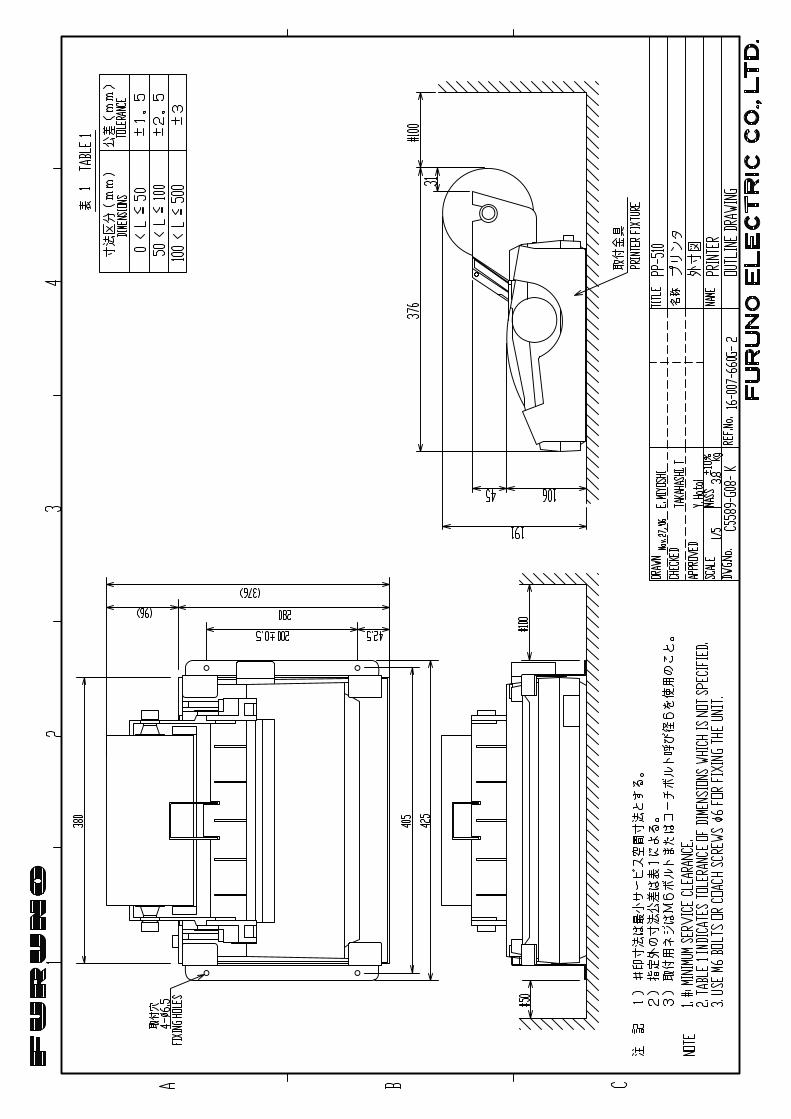
Printer (option) Printer PP-510 To mount the printer, refer to the printer outline drawing at the back of this manual. 1. Select a flat surface. 2. Fix the mounting base to the mounting location with four screws (supplied). 3. Lay the printer on the top of the mounting base and fasten it with the mounting fixtures
(two at each side and one at rear).
Mounting Fixture
Mounting Fixture
Mounting Dimensions 300 (H) x 396 (W) mm
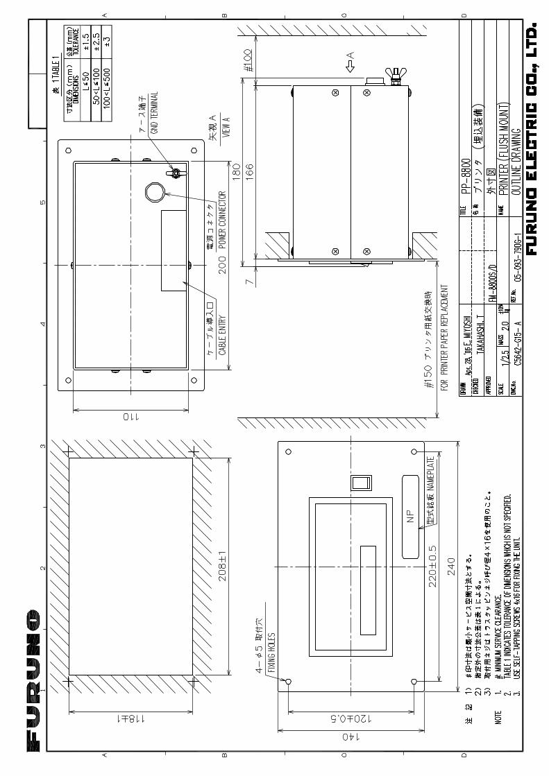
Mounting of Printer PP-510 Printer PP-8800
The printer PP-8800 is flush-mounted in a panel. Refer to the outline drawing at the back of this manual. 1. Make a cutout of 208(w) x 118(h) mm. 2. Set the printer and fix it with four self-tapping screws (4x16).
Printer Interface (option) The printer interface IF-8500 is required for the printer PP-510 which is commonly used with the FM-8800D/S and other MF/HF radio communication equipment. To mount the unit, see the outline drawing at the back of this manual.
External Loudspeaker (option) The external loudspeaker can be installed on a tabletop, the overhead or a bulkhead. Fasten the loudspeaker to the mounting location with self-tapping screws, or nuts, bolts and washers. For mounting dimensions, see the outline drawing at the back of this manual.

1. MOUNTING
1-7
Junction box IF-8810/ DMC interface IF-8820
Note: DMC interface IF-8820 is not used for Russian version. To install the remote box RB-8800/RB-8810, wing handset, etc., the junction box IF-8810 is required. Install the junction box near the transceiver unit. Approx. 3 m cable is preattached to the junction box to connect to the transceiver unit. To connect Furuno’s distress message controller DMC-5, the DMC interface IF-8820 (option) is required. 1. Open the cover. 2. Mount the unit with four self-tapping screws (5x20).
Fixing holes 5mm dia.
240
100 Note: This plug is notfitted in IF-8820.
Mounting the junction box/DMC interface

1. MOUNTING
1-8
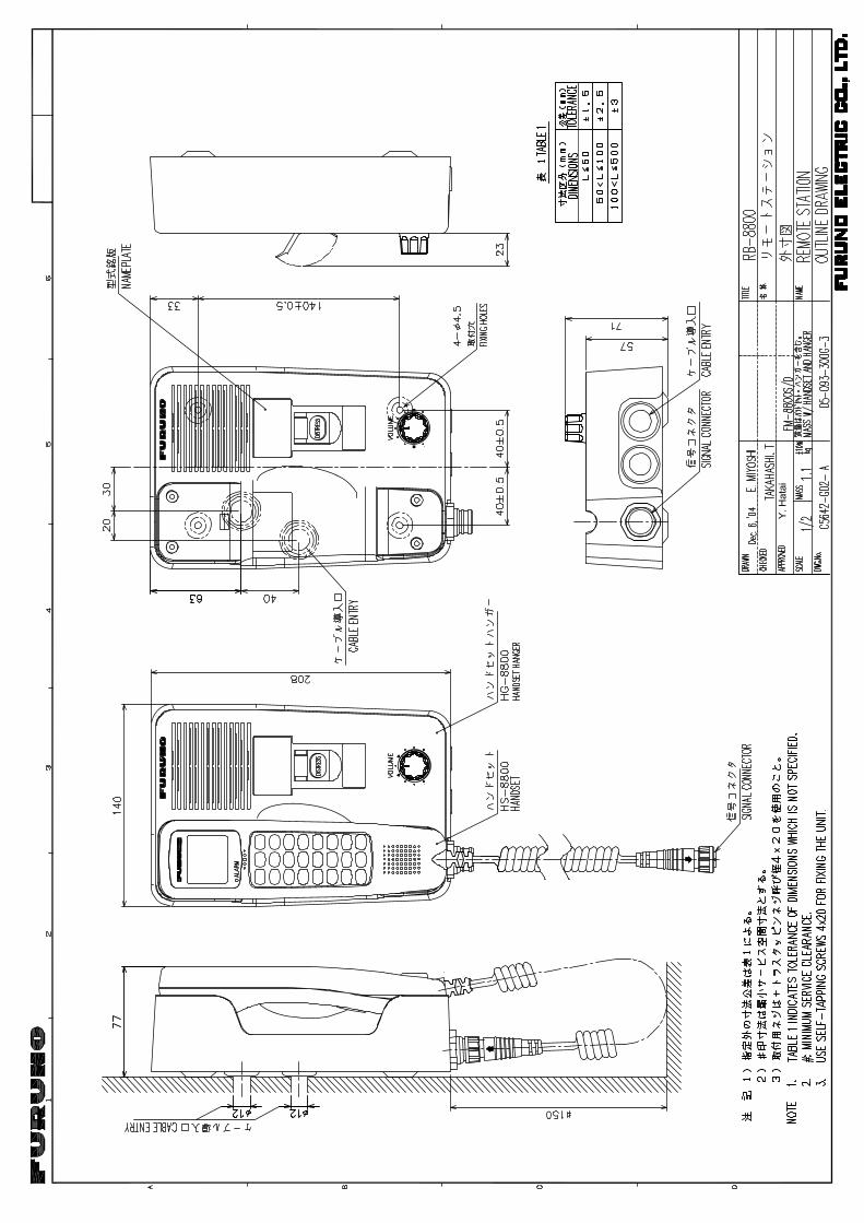
Remote station RB-8800/RB-8810 (option) Up to four remote stations can be connected in a daisy chain. Note: For the remote station RB-8800, there are two method of cable entry: bottom-side
entry and rear-side entry. For rear-side entry, make one or two holes of more than 12 mm diameter. For last station in the daisy chain, just one cable entry hole is needed.
1. Remove screws on the handset hanger (four for RB-8800, six for RB-8810). 2. Remove upper chassis of the hanger. 3. Mount the base of the hanger to a bulkhead with self-tapping screws 4x20 (four for
RB-8800), or 4x16 (two for RB-8810). 4. After connecting cables, assemble the remote station. 5. For RB-8800, attach blind seals on the screws.
Cab
le e
ntry
Cable entry(Rear)
77
#150
4063
40 0.5±
φ4- 4.514
0 0.
5±
33
HS-8800
HG-8800
VOLUME
DISTRESS
12φ
12φ
20 30
40 0.5±
Handset
Handset hanger
Screws 4 pcs.Attach blind sealon the screws. Cover of handset hanger
Nameplate
Cable entry(Bottom)
Fixing holes
Remote station RB-8800
HS-8800
HG-8810
12,
φ
Hanger Hanger mounting base
(77)
57
Handset
Hanger
Cab
le e
ntry
#150
(208
)
65
208
Nameplate
φ2- 4.5Fixing hole
145
0.5
±
22
Cable entry
42
Remote station RB-8810

1. MOUNTING
1-9
Outdoor mounting of waterproof-type remote station RB-8810-W
Remote station RB-8810-W (with waterproof-type handset HS-8800-W) can be mounted outdoors if it is set in a waterproof box. The hanger should be coated as directed below with silicone sealant for waterproofing. Note 1: Be sure to use a waterproof box to mount the RB-8810-W outdoors. The
waterproofing category of the RB-8810-W is IEC60529 IP56, however this should be protected from the weather (IEC 60945).
Note 2: Before sealing with silicone sealant (for waterproofing), do the termination setting (only for termination device, see page 2-7), connect cables and conduct the performance test. After sealing, do not open the handset hanger.
1. Fix the mounting base with self-tapping screws. Coat exposed part of these screws with
silicone sealant. 2. Attach the cable from the transceiver unit or junction box. Coat cable around cable
entrance with silicone sealant. 3. Fix the cover of the handset hanger. Coat junction between mounting base and cover
with silicone sealant.
2. Coat all around the cable at cable entry.
3. Coat all around the junction.
Note: Confirm that plastic washers are in screw holes before fixing cover.
1. Coat self-tapping screws.

1. MOUNTING
1-10
VHF console Install the rack console where the equipment can be easily operated, checked and serviced. Consult with shipyard personnel and ship's officer-in-charge to determine best location. The location must satisfy the following points: • Select a location where controls can be easily operated. • Select a location where shock and vibration are minimal. • Locate the console away from water splash and rain. • The temperature and humidity of the location should be both stable and moderate. Fixing
1. Ask shipyard personnel to tighten six M5 nuts or six M5 bolts to the fixing holes (on the wall), referring to the outline drawing at the back of this manual.
2. Detach the cover assembly from the console. 3. Hang VHF console on bolts. 4. Screw the console with the bolts or nuts tightly. 5. Attach the cover assembly to the console. Note: When you connect wires as soon as attaching console, refer to paragragh 2-10. 6. Attach the handset hanger with two screws. 7. To attach the optional emergency lamp, connect the cable to the terminal board, and
then attach the lamp to the console. Refer to the interconnection diagram and out line drawing.
(371)
(371)
330
250
298 ± 0.5
170
± 0.
5
145
170
± 0.
5
480
30
40
190
75°
40
(500
)
30
(266)
#50
EMG-1T
EMERGENCY LAMP
HANDSET HANGER
CABLE ENTRY (REAR)
FIXING HOLES
TERMINAL BOARD

2-1
2. CONNECTIONS
Overview The figure below shows where to connect various equipment at the rear of the transceiver unit.
EXT SPConnects externalloudspeaker.
ANTConnects antenna.
CH70 RX ANTConnects DSC antenna here.
24VDCConnects power cable.
PRINTERConnects printerPP-510.
Ground terminal.
IEC61162-1 (NMEA)/REMOTEConnects junction box IF-8810.
FM-8800D/8800S, rear view
Connection of Power Supply Convention vessels, 100/220 VAC ship’s mains Convention vessels must supply both AC and DC power to the FM-8800D/8800S, via an AC-DC power supply unit. Both AC and DC are supplied by the AC-DC power supply unit, and when AC input fails DC power is activated. Connect the radio battery to the DC IN terminal on the PR-240. Connect the AC ship’s mains to the AC IN terminal on the PR-240. Radio battery (24 VDC) Attach the connector supplied to the power cable and plug it into the 24VDC connector at the rear of the transceiver unit. Connect the wire ends to the radio battery line.

2. CONNECTIONS
2-2
Connection of VHF Antenna The VHF antenna is connected to the transceiver unit with a 50 ohm coaxial cable, type 5D-2V. Be sure to leave some slack in the cable for future service and maintenance. Lay the coaxial cable and attach an M-type plug to the cable (if necessary) as follows. 1. Remove the sheath by 20 mm. 2. Bare 13 mm of the center conductor. Trim braided shield by 5 mm and tin. 3. Slide coupling ring onto cable. 4. Screw the plug assembly on the cable. 5. Solder plug assembly to braided shield through solder holes. Solder contact sleeve to
conductor. 6. Screw coupling ring into plug assembly. 7. Screw the plug into the ANT connector at the rear of the transceiver unit.
How to attach the M-type plug to the coaxial cable

2. CONNECTIONS
2-3
Connection of DSC Antenna The DSC antenna is connected to the transceiver unit with a 50 ohm coaxial cable, type 5D-2V. Attach an M-type plug to the cable (if necessary) as shown an page 2-2. Screw the plug into the CH70 RX ANT connector at the rear of the transceiver unit.
Connection of Handset Connect the handset cable to the HANDSET connector on the front panel.
Grounding the Transceiver Unit Fasten a ground wire (local supply) between the GND terminal at the rear of the transceiver unit and ship’s hull (or ground bus).
Connecting the Junction Box The junction box is required to connect a remote station, wing handset, etc. The cable to be connected with the transceiver unit is prefitted on the junction box at the factory. For connection of other cables, see the interconnection diagram.
Cable entry
Cable clamp: Clamp shield part of the cables to ground cables.
Clamp the cable with U-type cable clamps.
Use one of these nuts for ground terminal between JB and ship's body.

2. CONNECTIONS
2-4
Connecting the Remote Station without the Junction Box The remote station (or DMC Interface, Mic. Receptacle box, etc) can be connected directly to the transceiver unit, using the D-sub connector supplied as installation materials. Attach the connector to the cable as follows.
Shield tape (metal)Fold back the armor, and then wind the shield tape along the edge of cable.
Cable clamp
Cable
Connector XM2A-3701 &Housing case XM2S-3712
Attachment of connector
When the handset HS-2003 is not connected to the Transceiver unit When the handset HS-2003 is not connected to the transceiver unit, i.e.,always the remoted handset is used, the following modification is necessary. 1. Dismount the cover of the transceiver unit by removing four screws at the rear panel and
two screws at the side. 2. Dismount the bottom cover by removing seven screws.
CPU board05P0773
J15
3. Shorten between #1 and #2 of J15. The handset line of the HANDSET port becomes
always “ON HOOK”. 4. Assemble the unit.
2. CONNECTIONS
2-5
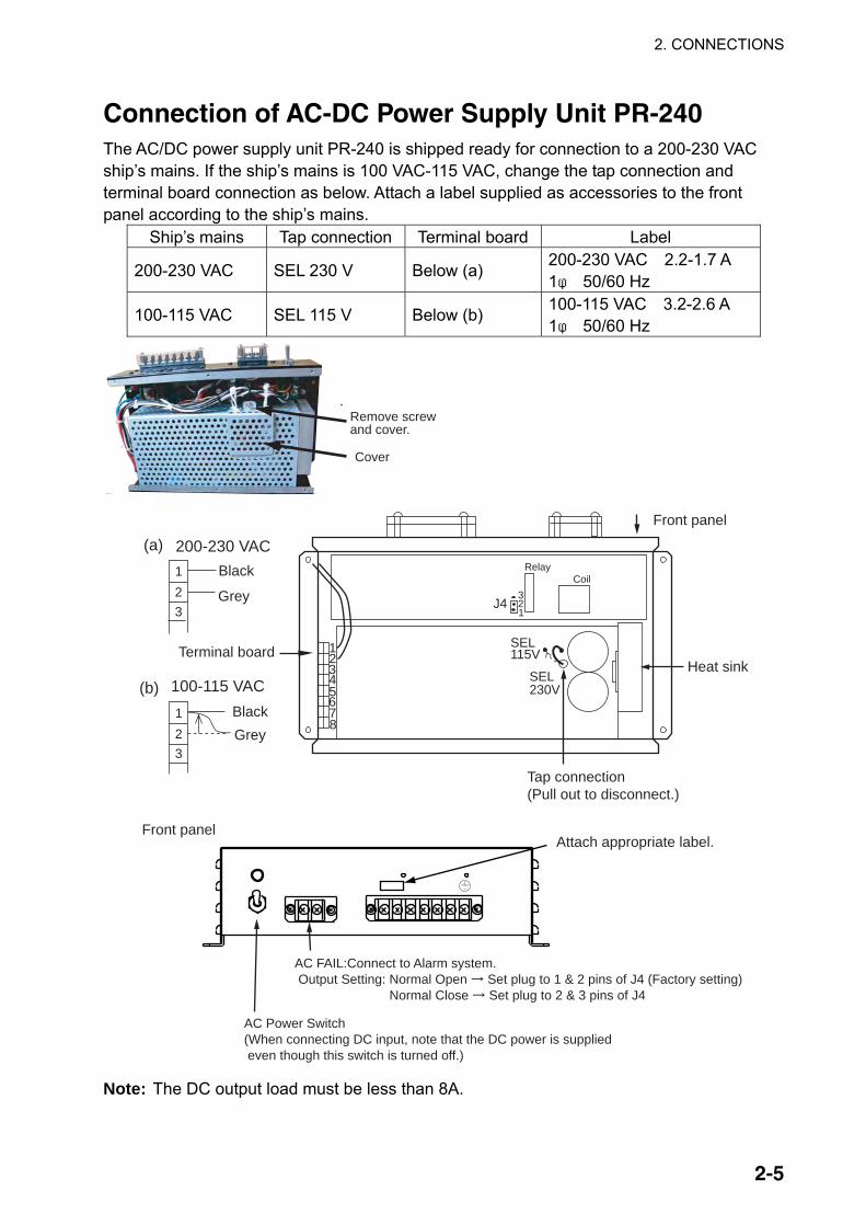
Connection of AC-DC Power Supply Unit PR-240 The AC/DC power supply unit PR-240 is shipped ready for connection to a 200-230 VAC ship’s mains. If the ship’s mains is 100 VAC-115 VAC, change the tap connection and terminal board connection as below. Attach a label supplied as accessories to the front panel according to the ship’s mains.
Ship’s mains Tap connection Terminal board Label
200-230 VAC SEL 230 V Below (a) 200-230 VAC 2.2-1.7 A 1φ 50/60 Hz
100-115 VAC SEL 115 V Below (b) 100-115 VAC 3.2-2.6 A 1φ 50/60 Hz
Remove screw and cover.
Cover
12345678
SEL115V
SEL230V
123
100-115 VAC
123
200-230 VAC(a)
(b)
AC FAIL:Connect to Alarm system.� Output Setting: Normal Open Set plug to 1 & 2 pins of J4 (Factory setting) Normal Close Set plug to 2 & 3 pins of J4
AC Power Switch(When connecting DC input, note that the DC power is supplied even though this switch is turned off.)
Heat sink
Tap connection (Pull out to disconnect.)
Front panel
Terminal board
GreyBlack
Grey
Black
Attach appropriate label.Front panel
CoilRelay
3
12J4
Note: The DC output load must be less than 8A.
2. CONNECTIONS
2-6
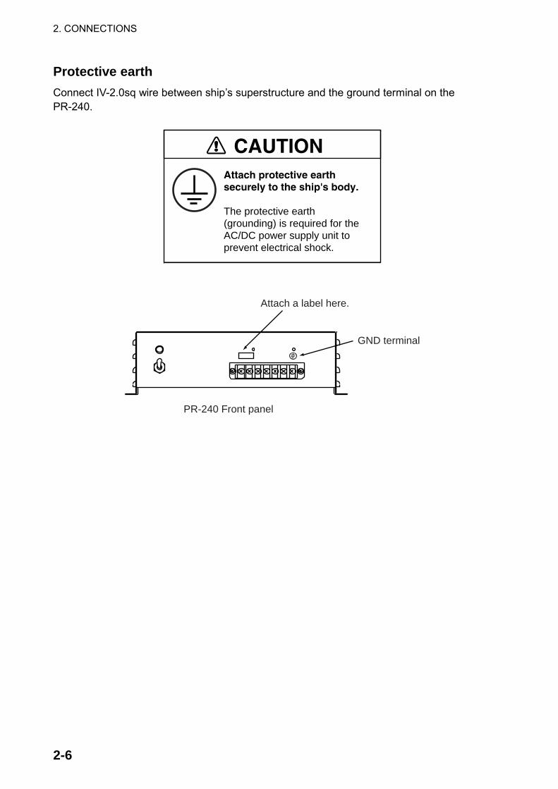
Protective earth Connect IV-2.0sq wire between ship’s superstructure and the ground terminal on the PR-240.
Attach protective earth securely to the ship's body.
The protective earth (grounding) is required for the AC/DC power supply unit to prevent electrical shock.
CAUTION
GND terminal
PR-240 Front panel
Attach a label here.
2. CONNECTIONS
2-7
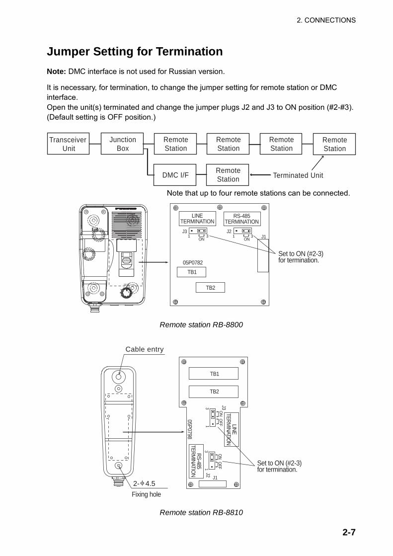
Jumper Setting for Termination Note: DMC interface is not used for Russian version. It is necessary, for termination, to change the jumper setting for remote station or DMC interface. Open the unit(s) terminated and change the jumper plugs J2 and J3 to ON position (#2-#3). (Default setting is OFF position.)
Transceiver Unit
JunctionBox
RemoteStation
RemoteStation
RemoteStation
RemoteStation
DMC I/F RemoteStation Terminated Unit
Note that up to four remote stations can be connected.
DISTRESS
VOLUME
TB1
TB2
05P0782
LINETERMINATION
RS-485TERMINATION
J31 3
ON
J21 3
ON J1
Set to ON (#2-3)for termination.
Remote station RB-8800
Set to ON (#2-3)for termination.
φ2- 4.5Fixing hole
Cable entry
TB1
TB2
05P0798
LINETERM
INATION
RS-485TERM
INATION
J3
13
ON
J1
OFF
13
ON
OFF
J2
Remote station RB-8810

2. CONNECTIONS
2-8
TB1
05P0778
RS-485TERMINATION
J4ON
Remove four screws to open the unit.
Set jumper plug to ON (#1-2).
DMC Interface IF-8820

2. CONNECTIONS
2-9
2.10 Wire connection of VHF console 1. Remove the cover assembly and printer assembly (or concealing lid) form the console.
For the printer assembly, remove the cables connected at the Transceiver Unit and the terminal board.
Cover assembly
Binding screw F M4X10 4 places
Console
Terminal board
Printer assemblyor Concealing lid
Binding screw F M4X10 8 places
2. Connect the power cable from the ship to the terminal block 1 (+) and 2 (-).
Power cablefrom the ship
Terminal board
1 2 3 4 5 6 7 8
- 1 2
1. Wiring conductor
2)Press the screwdriver to arrow direction to open the spring in the round hole.
1)Insert a screwdriver which blade edge is 3.5 X 0.5mm to the square hole.
4)Remove the screwdriver. 3)Insert the wire to the round hole.
Terminal Board Wiring
2. Wiring
Square hole
9~10mm
Round hole
3. Connect the ground wire from ship to each ground terminal for the transceiver unit and
the junction box. 4. Connect cables from external equipments to the junction box. 5. Fix the printer assembly (or concealing lid) and the cover assembly.

2. CONNECTIONS
2-10
Emergency Lamp Kit (Optional)
1. Remove the two screws from the position to place the lamp on the left or right side of the rack.
Remove the two screws
2. Insert the emergency lamp base into the fixing plate included with the kit. Affix the fixing
plate to the rack using the two screws from step one as shown.
Emergency lamp base
Mounting plate
Upwards
Cable entry
3. Insert the cable from the emergency lamp base into the cable entry of the rack. Connect the cable to terminal board, referring to the wiring diagram at the back of this manual.
4. Insert the emergency lamp connector into the lamp base.

3-1
3. ASSEMBLING CONSOLE KIT
A VHF console kit is required to mount the Transceiver Unit in the field. There are two types as shown below.
VHF console kit
Type Code No. Remarks RC-8800-N-75BG 000-054-125 Without printer RC-8800-A-75BG 000-054-126 With printer
Assembling the Console Kit 1. Remove the cover assembly, the panel assembly and the printer assembly (or
concealing lid) from the console. For the printer assembly, remove the cable connected to the terminal board.
Cover assembly
Binding screw FM4X10 8 places
#
Console
Remove screws( )and detach the panel assembly.
Panel assembly
Binding screw FM4X10 4 places
Printer assembly(or Concealing lid
#

3-2
2. Fix the panel assembly to the Transceiver Unit with binding screws (use original binding screws of the Transceiver Unit). Refer to the figure below.
3. Screw in hex bolts M8x16 and flat washers loosely at both sides of the Transceiver Unit. Panel assembly
Binding screw M4 2 places(Use the original screws of the Transceiver Unit.)
Hex bolt M8X162 places (faster loosely)
Washer M82 places
4. Set the Transceiver Unit to the console, remove the grommets from the console and fix
the Transceiver Unit with hex bolts using the holes formerly occupied by the grommets.
Hex head screws
Mountingplate
TransceiverUnit
Connecter
Connecter
Mounting of the Transceiver Unit
Close the hole with grommetslastly.
Flat washer
Insert console upside down.
Fix Mounting Platebetween washers.
5. Connect connector from the fuse to the power connector derived from the Transceiver Unit.

3-3
6. Replace the cable attached to junction box with the cable (55 cm, 37-pin D sub) supplied with the console kit.
2 3
J1 J2 J3
A
AReplace the original cable with the cable assemblyDSUB37M-PHX3-L550.
Junction box(without cover)
View
Crimp-on lug
PH Connector14P
PH Connector12P
PH Connector10P
7. Connect the cable (37-pin D sub) attached to the junction box to the Transceiver Unit
and then mount the junction box on the console.
±Screw B M4X10 4 places
Mounting plate
Cover
±Binding screw F M4X8 4 places

3-4
Grommets 2 placesJunction box
8. For the console w/printer, connect the printer cable for data transmission to the
PRINTER port of the Transceiver Unit and fix the power cable to the terminal board as before. Then, fix the printer assembly to the console. For no printer, fasten the concealing lid to the console.
Printer
J2
Printer cableW/ Printer
View
Insert the mounting plate for printer to the catch of the console
9. Fasten the cover assembly. NOTE: If the console assembly is to be mounted on the hull, refer to paragraghs 1-9 and
2-10.

NAME
OUTLINE
Q'TY
DESCRIPTION/CODE №
PA
CK
ING
L
IST
05EC-X-9851-8
FM-8800(S/D)-(J/E/F)-HS-N
1/1
NAME
OUTLINE
Q'TY
DESCRIPTION/CODE №
ユニ
ット
UNIT
送受信
機
TRANSCEIVER UNIT
1
**
FM-8800S/D
000-054-225-00
予備
品SPARE PARTS
SP05-05501
予備品
SPARE PARTS
1SP05-05501
005-377-820-00
付属
品ACCESSORIES
FP05-05700
ハンドセット
HANDSET
1HS-2003-15
000-015-996-00
ハンドセットハンガー組
品
BRACKET FOR HANDSET
1FP05-05510
005-951-790-00
付属品
ACCESSORIES
1FP05-05511
005-951-920-00
工事
材料
INSTALLATION MATERIALS
CP05-09900
ケーブル組品
CABLE ASSY.
105S9371-2
000-151-711-12
工事材
料
INSTALLATION MATERIALS
1CP05-09901
005-377-800-00
図書
DOCUMENT
取扱説
明書
OPERATOR'S MANUAL
1
**
OM*-56420-*
000-149-929-1*
操作要
領書
OPERATOR'S GUIDE
1
**
OS*-56420-*
000-149-933-1*
装備要
領書
INSTALLATION MANUAL
1
**
IM*-56420-*
000-149-931-1*
遭難警報フロ-(VHF/MF))
VHF/MF DISTRESS ALERT
FLOW
1
**
*52-00101-*
000-809-269-1*
遭難通
信要領書(和/英
)
DISTRESS PROCEDURE
1TIC-56420-*
000-149-935-1*
コ-ド
番号
末尾
の[*
*]は
、選
択品
の代
表型
式/コー
ドを
表し
ます
。
CO
DE N
UM
BER
EN
DIN
G W
ITH
"**" IN
DIC
ATES T
HE C
OD
E N
UM
BER
OF R
EP
RESEN
TA
TIV
E M
ATER
IAL.
(略
図の
寸法
は、
参考
値で
す。
DIM
EN
SIO
NS IN
DR
AW
ING
FO
R R
EFER
EN
CE O
NLY.)
05EC-X-9851
型式
/コー
ド番
号が
2段
の場
合、
下段
より
上段
に代
わる
過渡
期品
であ
り、
どち
らか
が入
って
いま
す。
な
お、
品質
は変
わり
ませ
ん。
TW
O T
YP
ES
AN
D C
OD
ES
MA
Y B
E L
ISTED
FO
R A
N ITEM
. T
HE L
OW
ER
PR
OD
UC
T M
AY B
E S
HIP
PED
IN
PLA
CE O
F
TH
E U
PP
ER
PR
OD
UC
T. Q
UA
LIT
Y IS
TH
E S
AM
E.

NAME
OUTLINE
Q'TY
DESCRIPTION/CODE №
PA
CK
ING
L
IST
05EC-X-9856-8
FM-8800(S/D)-(J/E/F)-HS-A/(-HK)
1/1
NAME
OUTLINE
Q'TY
DESCRIPTION/CODE №
ユニ
ット
UNIT
送受信
機
TRANSCEIVER UNIT
1
**
FM-8800S/D
000-054-225-00
接続箱
JUNCTION BOX
1IF-8810
000-054-219-00
予備
品SPARE PARTS
予備品
SPARE PARTS
1SP05-05501
005-377-820-00
付属
品ACCESSORIES
FP05-05700
ハンドセット
HANDSET
1HS-2003-15
000-015-996-00
ハンドセットハンガー組
品
BRACKET FOR HANDSET
1FP05-05510
005-951-790-00
付属品
ACCESSORIES
1FP05-05511
005-951-920-00
工事
材料
INSTALLATION MATERIALS
CP05-09900
ケーブル組品
CABLE ASSY.
105S9371-2
000-151-711-12
工事材
料
INSTALLATION MATERIALS
1CP05-09901
005-377-800-00
工事
材料
INSTALLATION MATERIALS
CP05-08701
工事材
料
INSTALLATION MATERIALS
1CP05-08701
005-949-280-00
図書
DOCUMENT
取扱説
明書
OPERATOR'S MANUAL
1
**
OM*-56420-*
000-149-929-1*
操作要
領書
OPERATOR'S GUIDE
1
**
OS*-56420-*
000-149-933-1*
装備要
領書
INSTALLATION MANUAL
1
**
IM*-56420-*
000-149-931-1*
遭難警報フロ-(VHF/MF))
VHF/MF DISTRESS ALERT
FLOW
1
**
*52-00101-*
000-809-269-1*
遭難通
信要領書(和/英
)
DISTRESS PROCEDURE
1TIC-56420-*
000-149-935-1*
コ-ド
番号
末尾
の[*
*]は
、選
択品
の代
表コー
ドを
表し
ます
。
CO
DE N
UM
BER
EN
DIN
G W
ITH
"**" IN
DIC
ATES T
HE C
OD
E N
UM
BER
OF R
EP
RESEN
TA
TIV
E M
ATER
IAL.
(略
図の
寸法
は、
参考
値で
す。
DIM
EN
SIO
NS IN
DR
AW
ING
FO
R R
EFER
EN
CE O
NLY.)
05EC-X-9856
型式
/コー
ド番
号が
2段
の場
合、
下段
より
上段
に代
わる
過渡
期品
であ
り、
どち
らか
が入
って
いま
す。
な
お、
品質
は変
わり
ませ
ん。
TW
O T
YP
ES
AN
D C
OD
ES
MA
Y B
E L
ISTED
FO
R A
N ITEM
. T
HE L
OW
ER
PR
OD
UC
T M
AY B
E S
HIP
PED
IN
PLA
CE O
F
TH
E U
PP
ER
PR
OD
UC
T. Q
UA
LIT
Y IS
TH
E S
AM
E.

NAME
OUTLINE
Q'TY
DESCRIPTION/CODE №
PA
CK
ING
L
IST
05EC-X-9858-5
FM-8800(S/D)-(E/F)-MIC-N
1/1
NAME
OUTLINE
Q'TY
DESCRIPTION/CODE №
ユニ
ット
UNIT
送受信
機
TRANSCEIVER UNIT
1
**
FM-8800S/D
000-054-225-00
予備
品SPARE PARTS
予備品
SPARE PARTS
1SP05-05501
005-377-820-00
付属
品ACCESSORIES
FP05-05710
マイクロフォン箱詰品
MICROPHONE
1DM-2003-F
005-377-760-00
工事
材料
INSTALLATION MATERIALS
CP05-09900
ケーブル組品
CABLE ASSY.
105S9371-2
000-151-711-12
工事材
料
INSTALLATION MATERIALS
1CP05-09901
005-377-800-00
図書
DOCUMENT
取扱説
明書(英
)
OPERATOR'S MANUAL
1OME-56420-*
000-149-930-1*
操作要
領書(英
)
OPERATOR'S GUIDE
1OSE-56420-*
000-149-934-1*
装備要
領書(英
)
INSTALLATION MANUAL
1IME-56420-*
000-149-932-1*
遭難警報フロ-(VHF/MF)(英)
DISTRESS ALERT
CHART(VHFMF)
1E52-00101-*
000-809-270-1*
遭難通
信要領書(和/英
)
DISTRESS PROCEDURE
1TIC-56420-*
000-149-935-1*
コ-ド
番号
末尾
の[*
*]は
、選
択品
の代
表コー
ドを
表し
ます
。
CO
DE N
UM
BER
EN
DIN
G W
ITH
"**" IN
DIC
ATES T
HE C
OD
E N
UM
BER
OF R
EP
RESEN
TA
TIV
E M
ATER
IAL.
(略
図の
寸法
は、
参考
値で
す。
DIM
EN
SIO
NS IN
DR
AW
ING
FO
R R
EFER
EN
CE O
NLY.)
05EC-X-9858
型式
/コー
ド番
号が
2段
の場
合、
下段
より
上段
に代
わる
過渡
期品
であ
り、
どち
らか
が入
って
いま
す。
な
お、
品質
は変
わり
ませ
ん。
TW
O T
YP
ES
AN
D C
OD
ES
MA
Y B
E L
ISTED
FO
R A
N ITEM
. T
HE L
OW
ER
PR
OD
UC
T M
AY B
E S
HIP
PED
IN
PLA
CE O
F
TH
E U
PP
ER
PR
OD
UC
T. Q
UA
LIT
Y IS
TH
E S
AM
E.

NAME
OUTLINE
Q'TY
DESCRIPTION/CODE №
PA
CK
ING
L
IST
05EC-X-9859-6
FM-8800(S/D)-(E/F)-MIC-A
1/1
NAME
OUTLINE
Q'TY
DESCRIPTION/CODE №
ユニ
ット
UNIT
接続箱
JUNCTION BOX
1IF-8810
000-054-219-00
送受信
機
TRANSCEIVER UNIT
1
**
FM-8800S/D
000-054-225-00
予備
品SPARE PARTS
予備品
SPARE PARTS
1SP05-05501
005-377-820-00
付属
品ACCESSORIES
FP05-05710
マイクロフォン箱詰品
MICROPHONE
1DM-2003-F
005-377-760-00
工事
材料
INSTALLATION MATERIALS
CP05-09900
ケーブル組品
CABLE ASSY.
105S9371-2
000-151-711-12
工事材
料
INSTALLATION MATERIALS
1CP05-09901
005-377-800-00
工事
材料
INSTALLATION MATERIALS
工事材
料
INSTALLATION MATERIALS
1CP05-08701
005-949-280-00
図書
DOCUMENT
取扱説
明書(英
)
OPERATOR'S MANUAL
1OME-56420-*
000-149-930-1*
操作要
領書(英
)
OPERATOR'S GUIDE
1OSE-56420-*
000-149-934-1*
装備要
領書(英
)
INSTALLATION MANUAL
1IME-56420-*
000-149-932-1*
遭難警報フロ-(VHF/MF)(英)
DISTRESS ALERT
CHART(VHFMF)
1E52-00101-*
000-809-270-1*
遭難通
信要領書(和/英
)
DISTRESS PROCEDURE
1TIC-56420-*
000-149-935-1*
コ-ド
番号
末尾
の[*
*]は
、選
択品
の代
表コー
ドを
表し
ます
。
CO
DE N
UM
BER
EN
DIN
G W
ITH
"**" IN
DIC
ATES T
HE C
OD
E N
UM
BER
OF R
EP
RESEN
TA
TIV
E M
ATER
IAL.
(略
図の
寸法
は、
参考
値で
す。
DIM
EN
SIO
NS IN
DR
AW
ING
FO
R R
EFER
EN
CE O
NLY.)
05EC-X-9859
型式
/コー
ド番
号が
2段
の場
合、
下段
より
上段
に代
わる
過渡
期品
であ
り、
どち
らか
が入
って
いま
す。
な
お、
品質
は変
わり
ませ
ん。
TW
O T
YP
ES
AN
D C
OD
ES
MA
Y B
E L
ISTED
FO
R A
N ITEM
. T
HE L
OW
ER
PR
OD
UC
T M
AY B
E S
HIP
PED
IN
PLA
CE O
F
TH
E U
PP
ER
PR
OD
UC
T. Q
UA
LIT
Y IS
TH
E S
AM
E.

A-6
A-5

A-8
A-7

A-1
0A
-9

A-12
Use
d o
nly
Ja
pa
n
A-1
1

A-14
A-13

A-15

NAME
OUTLINE
Q'TY
DESCRIPTION/CODE №
PA
CK
ING
L
IST
05EC-X-9864-3
FM-8800S-R-HS-N
1/1
NAME
OUTLINE
Q'TY
DESCRIPTION/CODE №
ユニ
ット
UNIT
送受信
機
TRANSCEIVER UNIT
1FM-8800S-R
000-054-404-00
予備
品SPARE PARTS
SP05-05501
予備品
SPARE PARTS
1SP05-05501
005-377-820-00
付属
品ACCESSORIES
FP05-05700
ハンドセット
HANDSET
1HS-2003-15
000-015-996-00
ハンドセットハンガー組
品
BRACKET FOR HANDSET
1FP05-05510
005-951-790-00
付属品
ACCESSORIES
1FP05-05511
005-951-920-00
工事
材料
INSTALLATION MATERIALS
CP05-09900
ケーブル組品
CABLE ASSY.
105S9371-2
000-151-711-12
工事材
料
INSTALLATION MATERIALS
1CP05-09901
005-377-800-00
図書
DOCUMENT
取扱説
明書(英
)
OPERATOR'S MANUAL
1OME-56421-*
000-161-430-1*
操作要
領書(英
)
OPERATOR'S GUIDE
1OSE-56420-*
000-149-934-1*
装備要
領書(英
)
INSTALLATION MANUAL
1IME-56420-*
000-149-932-1*
遭難警報フロ-(VHF/MF)(英)
DISTRESS ALERT
CHART(VHFMF)
1E52-00101-*
000-809-270-1*
遭難通
信要領書(和/英
)
DISTRESS PROCEDURE
1TIC-56420-*
000-149-935-1*
(略
図の
寸法
は、
参考
値で
す。
DIM
EN
SIO
NS IN
DR
AW
ING
FO
R R
EFER
EN
CE O
NLY.)
05EC-X-9864
型式
/コー
ド番
号が
2段
の場
合、
下段
より
上段
に代
わる
過渡
期品
であ
り、
どち
らか
が入
って
いま
す。
な
お、
品質
は変
わり
ませ
ん。
TW
O T
YP
ES
AN
D C
OD
ES
MA
Y B
E L
ISTED
FO
R A
N ITEM
. T
HE L
OW
ER
PR
OD
UC
T M
AY B
E S
HIP
PED
IN
PLA
CE O
F
TH
E U
PP
ER
PR
OD
UC
T. Q
UA
LIT
Y IS
TH
E S
AM
E.

NAME
OUTLINE
Q'TY
DESCRIPTION/CODE №
PA
CK
ING
L
IST
05EC-X-9865-2
FM-8800S-R-MIC-N
1/1
NAME
OUTLINE
Q'TY
DESCRIPTION/CODE №
ユニ
ット
UNIT
送受信
機
TRANSCEIVER UNIT
1FM-8800S-R
000-054-404-00
予備
品SPARE PARTS
SP05-05501
予備品
SPARE PARTS
1SP05-05501
005-377-820-00
付属
品ACCESSORIES
FP05-05710
マイクロフォン箱詰品
MICROPHONE
1DM-2003-F
005-377-760-00
工事
材料
INSTALLATION MATERIALS
CP05-09900
ケーブル組品
CABLE ASSY.
105S9371-2
000-151-711-12
工事材
料
INSTALLATION MATERIALS
1CP05-09901
005-377-800-00
図書
DOCUMENT
取扱説
明書
OPERATOR'S MANUAL
1OME-56421-*
000-161-430-1*
操作要
領書(英
)
OPERATOR'S GUIDE
1OSE-56420-*
000-149-934-1*
装備要
領書(英
)
INSTALLATION MANUAL
1IME-56420-*
000-149-932-1*
遭難警報フロ-(VHF/MF)(英)
DISTRESS ALERT
CHART(VHFMF)
1E52-00101-*
000-809-270-1*
遭難通
信要領書(和/英
)
DISTRESS PROCEDURE
1TIC-56420-*
000-149-935-1*
(略
図の
寸法
は、
参考
値で
す。
DIM
EN
SIO
NS IN
DR
AW
ING
FO
R R
EFER
EN
CE O
NLY.)
05EC-X-9865
型式
/コー
ド番
号が
2段
の場
合、
下段
より
上段
に代
わる
過渡
期品
であ
り、
どち
らか
が入
って
いま
す。
な
お、
品質
は変
わり
ませ
ん。
TW
O T
YP
ES
AN
D C
OD
ES
MA
Y B
E L
ISTED
FO
R A
N ITEM
. T
HE L
OW
ER
PR
OD
UC
T M
AY B
E S
HIP
PED
IN
PLA
CE O
F
TH
E U
PP
ER
PR
OD
UC
T. Q
UA
LIT
Y IS
TH
E S
AM
E.

NAME
OUTLINE
Q'TY
DESCRIPTION/CODE №
PA
CK
ING
L
IST
05EC-X-9866-3
FM-8800S-R-HS-A
1/1
NAME
OUTLINE
Q'TY
DESCRIPTION/CODE №
ユニ
ット
UNIT
接続箱
JUNCTION BOX
1IF-8810
000-054-219-00
送受信
機
TRANSCEIVER UNIT
1FM-8800S-R
000-054-404-00
予備
品SPARE PARTS
予備品
SPARE PARTS
1SP05-05501
005-377-820-00
付属
品ACCESSORIES
FP05-05700
ハンドセット
HANDSET
1HS-2003-15
000-015-996-00
ハンドセットハンガー組
品
BRACKET FOR HANDSET
1FP05-05510
005-951-790-00
付属品
ACCESSORIES
1FP05-05511
005-951-920-00
工事
材料
INSTALLATION MATERIALS
CP05-09900
ケーブル組品
CABLE ASSY.
105S9371-2
000-151-711-12
工事材
料
INSTALLATION MATERIALS
1CP05-09901
005-377-800-00
工事
材料
INSTALLATION MATERIALS
CP05-08701
工事材
料
INSTALLATION MATERIALS
1CP05-08701
005-949-280-00
図書
DOCUMENT
取扱説
明書(英
)
OPERATOR'S MANUAL
1OME-56421-*
000-161-430-1*
操作要
領書(英
)
OPERATOR'S GUIDE
1OSE-56420-*
000-149-934-1*
装備要
領書(英
)
INSTALLATION MANUAL
1IME-56420-*
000-149-932-1*
遭難警報フロ-(VHF/MF)(英)
DISTRESS ALERT
CHART(VHFMF)
1E52-00101-*
000-809-270-1*
遭難通
信要領書(和/英
)
DISTRESS PROCEDURE
1TIC-56420-*
000-149-935-1*
(略
図の
寸法
は、
参考
値で
す。
DIM
EN
SIO
NS IN
DR
AW
ING
FO
R R
EFER
EN
CE O
NLY.)
05EC-X-9866
型式
/コー
ド番
号が
2段
の場
合、
下段
より
上段
に代
わる
過渡
期品
であ
り、
どち
らか
が入
って
いま
す。
な
お、
品質
は変
わり
ませ
ん。
TW
O T
YP
ES
AN
D C
OD
ES
MA
Y B
E L
ISTED
FO
R A
N ITEM
. T
HE L
OW
ER
PR
OD
UC
T M
AY B
E S
HIP
PED
IN
PLA
CE O
F
TH
E U
PP
ER
PR
OD
UC
T. Q
UA
LIT
Y IS
TH
E S
AM
E.

NAME
OUTLINE
Q'TY
DESCRIPTION/CODE №
PA
CK
ING
L
IST
05EC-X-9867-2
FM-8800S-R-MIC-A
1/1
NAME
OUTLINE
Q'TY
DESCRIPTION/CODE №
ユニ
ット
UNIT
接続箱
JUNCTION BOX
1IF-8810
000-054-219-00
送受信
機
TRANSCEIVER UNIT
1FM-8800S-R
000-054-404-00
予備
品SPARE PARTS
SP05-05501
予備品
SPARE PARTS
1SP05-05501
005-377-820-00
付属
品ACCESSORIES
FP05-05710
マイクロフォン箱詰品
MICROPHONE
1DM-2003-F
005-377-760-00
工事
材料
INSTALLATION MATERIALS
CP05-09900
ケーブル組品
CABLE ASSY.
105S9371-2
000-151-711-12
工事材
料
INSTALLATION MATERIALS
1CP05-09901
005-377-800-00
工事
材料
INSTALLATION MATERIALS
CP05-08701
工事材
料
INSTALLATION MATERIALS
1CP05-08701
005-949-280-00
図書
DOCUMENT
取扱説
明書(英
)
OPERATOR'S MANUAL
1OME-56421-*
000-161-430-1*
操作要
領書(英
)
OPERATOR'S GUIDE
1OSE-56420-*
000-149-934-1*
装備要
領書(英
)
INSTALLATION MANUAL
1IME-56420-*
000-149-932-1*
遭難警報フロ-(VHF/MF)(英)
DISTRESS ALERT
CHART(VHFMF)
1E52-00101-*
000-809-270-1*
遭難通
信要領書(和/英
)
DISTRESS PROCEDURE
1TIC-56420-*
000-149-935-1*
(略
図の
寸法
は、
参考
値で
す。
DIM
EN
SIO
NS IN
DR
AW
ING
FO
R R
EFER
EN
CE O
NLY.)
05EC-X-9867
型式
/コー
ド番
号が
2段
の場
合、
下段
より
上段
に代
わる
過渡
期品
であ
り、
どち
らか
が入
って
いま
す。
な
お、
品質
は変
わり
ませ
ん。
TW
O T
YP
ES
AN
D C
OD
ES
MA
Y B
E L
ISTED
FO
R A
N ITEM
. T
HE L
OW
ER
PR
OD
UC
T M
AY B
E S
HIP
PED
IN
PLA
CE O
F
TH
E U
PP
ER
PR
OD
UC
T. Q
UA
LIT
Y IS
TH
E S
AM
E.


Y.Hatai

Y.Hatai

26/Oct/09 R.Esumi


Dec.26'06 R.Esumi

1 5432
A
B
C
D
6
INTERCONNECTION DIAGRAM
相互結線図
FURUNO ELECTRIC CO., LTD.
CHECKED
APPROVED
DRAWN
SCALE
DWG No.
T.YAMASAKI
CO-0.2x5P: CO-SPEVV-SB-C 0.2x5P,φ13.5CO-0.2x2P: CO-SPEVV-SB-C 0.2x2P,φ10.5
T.TAKENO
kgMASS
名称
NAME
TITLE
*5)終端ユニットは内部のジャンパー(J2,J3)をONにする。
*4)ケーブルクランプで接地。
*3)最大4台まで接続可能。
*2)オプション。
*1)造船所手配。
注記
*4. GROUND THROUGH CABLE CLAMP.
NOTE
*1. SHIPYARD SUPPLY*2. OPTION*3. MAX. 4 SETS AVAILABLE
*5. CONNECT JUMPERS (J2 & J3) ON TERMINATED REMOTE STATION.
*6)ノーマルクローズ、フローティング、最大80mA、耐圧≦50V。 *6. NORMAL CLOSE, FLOATING, MAX80mA, WITHSTAND VOLTAGE ≦50V.
国際VHF無線電話装置
VHF RADIOTELEPHONE
FM-8800D/S
*5
CH70 RX ANT
送受信機
FM-8800D/STRANSCEIVER UNIT
ANT
NC+15VDC+15VDC+15VDC+15VDC
J212
F.GND0V
W_PTT2-NW_SP2-CW_SP2-H
W_MIC2-CW_MIC2-H
LINE IN-CLINE IN-H
LINE OUT-CLINE OUT-H
DATA-BDATA-A
VDR AF-CVDR AF-H 23
2425262728293031323334353637
P
P
P
P
P
P
P
W_PTT1-NW_SP1-CW_SP1-H
W_MIC1-CW_MIC1-H
0V0V0V0V0V
1312
141516171819202122
P
P
P
P
P
EXT.ALM-N 11P
0V
RXD-CRXD-HTXD-CTXD-H
NC
12345
678910
XM2A-3701
P
P
P
P
P
IEC61162-1(NMEA)/REMOTE
P
P
J1
10987654321
J2
121110987654321
J3
1413121110987654321
F.GND0V
W_PTT1-NW_SP1-CW_SP1-H
W_MIC1-CW_MIC1-H
F.GND0V
EXT.ALM-NF.GNDRXD-CRXD-HTXD-CTXD-H
F.GND0V
W_PTT2-NW_SP2-CW_SP2-H
W_MIC2-CW_MIC2-H
F.GNDNOT USED_2NOT USED_1
VDR AF-CVDR AF-H
NCF.GND
LINE OUT-CLINE OUT-HLINE IN-CLINE IN-H
DATA-BDATA-A
0V+15VDC
NCF.GND
LINE OUT-CLINE OUT-HLINE IN-CLINE IN-H
DATA-BDATA-A
0V+15VDC
NC
P
P
123456789101112131415
*4
*4TTYCS-1,MAX.20m
*1
EXTERNAL ALARM外部アラーム
YELWHTYELBLKYELRED
キシロキクロキアカ TB1
1234 5
4321
YELWHTYELBLKYELREDアカ
クロ
シロキ
キ
キTB1
54321
1234
TTYCS-1,MAX.20m*1
VDR
*4
終端まで最長50mTOTAL 50m OR LESS TO TERMINATE
ORGYEL
ダイキ
BRNRED
チャアカ
BLUGRNBLK[B]WHT[B]
アオミドリクロ(太)シロ(太)
P
P
P
P
終端まで最長50mTOTAL 50m OR LESS TO TERMINATE
ORGYEL
ダイキ
BRNRED
チャアカ
BLUGRNBLK[B]WHT[B]
アオミドリクロ(太)シロ(太)
P
P
P
P
3839404142434445464748
16171819202122
2324252627
28293031323334353637
F.GNDRXD-CRXD-HTXD-CTXD-H
2423222120
109
12345678
F.GNDNCF.GND
IF-8820DMC I/F
*2
191817161514131211
<No.1>
LINE OUT-CLINE OUT-HLINE IN-CLINE IN-H
TB2TB112345678
12345678
HS-6000FZ-5
*2HS-6000FZ-11HANDSETハンドセット
HS-6000FZ-5
*2HS-6000FZ-11HANDSETハンドセット
TB2TB1
<No.3/No.4>
リモートステーションREMOTE STATION
<No.2>
リモートステーションREMOTE STATION
12345678
12345678
リモートステーションREMOTE STATION
TB1
*2
ハンドセットHANDSET
リモートステーションREMOTE STATION
*5
12345678
RXD-CRXD-HTXD-CTXD-H
TB1/TB2 遭難警報装置
F.GND
12345
Wing Mic
Wing Mic
REMOTE STATIONRB-8800/8810/8810W RB-8800/8810/8810W
HS-8800/8800Wハンドセット
HS-8800/8800Wハンドセット
*4SHIELD
*4SHIELD G G
05S0309*2
ORGYEL
ダイ
BRNRED
チャアカ
BLUGRNBLK[B]WHT[B]
アオミドリクロ(太)シロ(太)
キ
SHIELD
05S0309*2
ORGYEL
ダイ
BRNRED
チャアカ
BLUGRNBLK[B]WHT[B]
アオミドリクロ(太)シロ(太)
キ
GSHIELD
接続箱
IF-8810JUNCTION BOX
CO-0.2x2P (*2)TTYCS-4(*1) OR
*2CO-0.2x5P,MAX.20m
*2CO-0.2x5P,MAX.20m
RB-8800/8810/8810WHS-8800/8800W
RB-8800/8810/8810W
DMC-5CONTROLLERDISTRESS MESSAGE
05S0309*2
05S0309*2
CO-0.2x2P,MAX.30m*2
RB-8800/8810/8810W
航法装置/プロッタ
NAVIGATOR/PLOTTER
リモートステーション
1 1 10
10
*2HANDSET
*2HANDSET
P
P
P
P
P
P
マイクレセプタクル
*2
ボックスMIC RECEPTACLEBOXRBD-VHF(B)
マイクレセプタクルボックスMIC RECEPTACLEBOXRBD-VHF(B) *2
HANDSET
HS-2003
ハンドセット
EXT. SPEAKERSEM-21Q
外部スピーカ
*2
2.8m
12
J1
12345678
HANDSET
HS SP-HMIC-CMIC-H
HOOK SW-N
PTT SW-NS.GND
F.GND
φ3.5 SPKR
SP-CSP-H
+5V
*6
24VDC(+)24VDC(-)
05S9371,3m
BLKRED
15A
*1IV-1.25sq.
5m
T/R用アンテナANTENNA FOR T/R
*2
*2CH70 WR用アンテナANTENNA FOR CH70 WR
24VDC
+
+
-
-
100-115/200-230VAC
24VDC
DPYC-1.5*1
ACIN
DCIN
DCOUT
SUPPLY UNITAC/DC POWER
AC/DC電源ユニット
*1IV-2sq.
PE保護アース
DPYC-4*1
1
25
PRINTER17JE-23250-02(D8C)
*1IV-2sq.
GND
1φ,50/60Hz
21
3
24V+
GNDBLKRED
WHT
アカクロシロ
1 36~
~または OR
2BLKクロWHTシロ 1
36
24VDC
24VDC
*1IV-1.25sq.
*2PRINTERプリンタ
PP-510
PRINTERプリンタ
0V
J1
FM14-2S(+)(-)
57FE-30360
-20N(D8)
1
VCTF0.75x2C,3m
VCTF0.75x3C,5m
RG-10/UY*1
RG-10/UY*1
(16S0084)
RM12BPE-3S
(05S0441)*2
PP-8800A
M-P-7
M-P-7
16S0184,3m
*2 *3 *2 *3
*2
PR-240
6
6
26/Jan/10
26/Jan/10
C5642-C01- N
8/Mar/10 R.Esumi

1 5432
A
B
C
D
6
FURUNO ELECTRIC CO., LTD.
CHECKED
APPROVED
DRAWN
SCALE
DWG No.
T.YAMASAKI
CO-0.2x5P: CO-SPEVV-SB-C 0.2x5P,φ13.5CO-0.2x2P: CO-SPEVV-SB-C 0.2x2P,φ10.5
T.TAKENO
kgMASS
名称
NAME
TITLE FM-8800D/S
国際VHF無線電話装置(接続箱なし)
VHF RADIOTELEPHONE (W/O JUNCTION BOX)
相互結線図
INTERCONNECTION DIAGRAM
CH70 RX ANT
送受信機
FM-8800D/STRANSCEIVER UNIT
ANT
J212
XM2A-3701IEC61162-1(NMEA)/REMOTE
HANDSET
HS-2003
ハンドセット
EXT. SPEAKERSEM-21Q
外部スピーカ
*2
2.8m
12
J1
12345678
HANDSET
HS SP-HMIC-CMIC-H
HOOK SW-N
PTT SW-NS.GND
F.GND
φ3.5 SPKR
SP-CSP-H
+5V
T/R用アンテナANTENNA FOR T/R
*2
*2CH70 WR用アンテナANTENNA FOR CH70 WR
RG-10/UY*1
RG-10/UY*1
M-P-7
M-P-7
LINE IN-CLINE IN-H
LINE OUT-CLINE OUT-H
DATA-BDATA-A
0V+15VDC
NC+15VDC+15VDC+15VDC
RXD-CRXD-HTXD-CTXD-H
NC
2345
678910
0V0V0V
12
202122
EXT.ALM-N 110V
VDR AF-CVDR AF-H 23
24
302928272625191
W_PTT1-NW_SP1-CW_SP1-H
W_MIC1-CW_MIC1-H
0V
131415161718
1
25
PRINTER17JE-23250-02(D8C)
F.GND0V
W_PTT2-NW_SP2-CW_SP2-H
W_MIC2-CW_MIC2-H
37363534333231
*1IV-2sq.
GND
24VDC(+)24VDC(-)
05S9371,3m
BLKRED
15A
+
+
-
-
DPYC-1.5*1
ACIN
DCIN
DCOUT
SUPPLY UNITAC/DC POWER
AC/DC電源ユニット
*1IV-2sq.
PE保護アース
DPYC-4*1
PR-240
16S0184,3m
21
3
24V+
GND
1 36~
~または OR
21
36
*1IV-1.25sq.
*2PRINTERプリンタ
PP-510
PRINTERプリンタ
0V
J1
FM14-2S(+)(-)
57FE-30360
-20N(D8)
1
RM12BPE-3S
*2PP-8800A
1φ,50/60Hz
100-115/200-230VAC
24VDC
24VDC
ORGYEL
ダイキ
BRNRED
チャアカ
BLUGRNBLK[B]WHT[B]
アオミドリクロ(太)シロ(太)
109
12345678
NCF.GND
IF-8820DMC I/F
*2
SHIELD
05S0309*2
P
P
F.GNDRXD-CRXD-HTXD-CTXD-H
2423222120
CO-0.2x2P,MAX.30m*2
YELWHTYELBLKYELREDアカ
クロ
シロキ
キ
キTB1
54321
1234
HS-6000FZ-5
*2HS-6000FZ-11HANDSETハンドセットマイクレセプタクル
ボックスMIC RECEPTACLEBOXRBD-VHF(B) *2
*2CO-0.2x5P,MAX.20m
Wing Mic
YELWHTYELBLKYELRED
キシロキクロキアカ TB1
1234 5
4321
HS-6000FZ-5
*2HS-6000FZ-11HANDSETハンドセット
*2CO-0.2x5P,MAX.20m
マイクレセプタクル
*2
ボックスMIC RECEPTACLEBOXRBD-VHF(B)
Wing Mic
EXTERNAL ALARM外部アラーム
航法装置/プロッタ
NAVIGATOR/PLOTTERCO-0.2x2P (*2)TTYCS-4(*1) OR
TTYCS-1,MAX.20m*1
VDR
P
P
P
P
P
P
P
P
P
P
P
P
TTYCS-1,MAX.20m*1
終端まで最長50mTOTAL 50m OR LESS TO TERMINATE
RXD-CRXD-HTXD-CTXD-H
TB1/TB2 遭難警報装置
F.GND
12345
DMC-5CONTROLLERDISTRESS MESSAGE
*4)ケーブルクランプで接地。
*3)最大4台まで接続可能。
*2)オプション。
*1)造船所手配。
注記
*4. GROUND THROUGH CABLE CLAMP.
NOTE
*1. SHIPYARD SUPPLY*2. OPTION*3. MAX. 4 SETS AVAILABLE
*5. NORMAL CLOSE, FLOATING, MAX80mA, WITHSTAND VOLTAGE ≦50V.*5)ノーマルクローズ、フローティング、最大80mA、耐圧≦50V。
*5
BLKRED
WHT
アカクロシロ
BLKクロWHTシロ
24VDC
24VDC VCTF0.75x2C,3m
VCTF0.75x3C,5m(16S0084)
(05S0441)
6
6
C5642-C03- F
26/Jan/10
26/Jan/10
8/Mar/10 R.Esumi

1 5432
A
B
C
D
6
送受信機
FM-8800D/STRANSCEIVER UNIT
NC+15VDC+15VDC+15VDC+15VDC
F.GND0V
W_PTT2-NW_SP2-CW_SP2-H
W_MIC2-CW_MIC2-H
LINE IN-CLINE IN-H
LINE OUT-CLINE OUT-H
DATA-BDATA-A
VDR AF-CVDR AF-H 23
2425262728293031323334353637
P
P
P
P
P
P
P
W_PTT1-NW_SP1-CW_SP1-H
W_MIC1-CW_MIC1-H
0V0V0V0V0V
1312
141516171819202122
P
P
P
P
P
EXT.ALM-N 11P
0V
RXD-CRXD-HTXD-CTXD-H
NC
12345
678910
XM2A-3701
P
P
P
P
P
IEC61162-1(NMEA)/REMOTE
P
P
J1
10987654321
J2
121110987654321
J3
1413121110987654321
F.GND0V
W_PTT1-NW_SP1-CW_SP1-H
W_MIC1-CW_MIC1-H
F.GND0V
EXT.ALM-NF.GNDRXD-CRXD-HTXD-CTXD-H
F.GND0V
W_PTT2-NW_SP2-CW_SP2-H
W_MIC2-CW_MIC2-H
F.GNDNOT USED_2NOT USED_1
VDR AF-CVDR AF-H
NCF.GND
LINE OUT-CLINE OUT-HLINE IN-CLINE IN-H
DATA-BDATA-A
0V+15VDC
NCF.GND
LINE OUT-CLINE OUT-HLINE IN-CLINE IN-H
DATA-BDATA-A
0V+15VDC
NC
P
P
123456789101112131415
*4
*4TTYCS-1,MAX.20m
*1
EXTERNAL ALARM外部アラーム
YELWHTYELBLKYELRED
キシロキクロキアカ TB1マイクレセプタクル
*2
ボックスMIC RECEPTACLEBOXRBD-VHF(B)
1234 5
4321
YELWHTYELBLKYELREDアカ
クロ
シロキ
キ
キマイクレセプタクルTB1
ボックスMIC RECEPTACLEBOXRBD-VHF(B) *2 5
4321
1234
TTYCS-1,MAX.20m*1
VDR
*4
終端まで最長50mTOTAL 50m OR LESS TO TERMINATE
ORGYEL
ダイキ
BRNRED
チャアカ
BLUGRNBLK[B]WHT[B]
アオミドリクロ(太)シロ(太)
P
P
P
P
終端まで最長50mTOTAL 50m OR LESS TO TERMINATE
ORGYEL
ダイキ
BRNRED
チャアカ
BLUGRNBLK[B]WHT[B]
アオミドリクロ(太)シロ(太)
P
P
P
P
3839404142434445464748
16171819202122
2324252627
28293031323334353637
F.GNDRXD-CRXD-HTXD-CTXD-H
2423222120
109
12345678
F.GNDNCF.GND
IF-8820DMC I/F
*2
191817161514131211
<No.1>
LINE OUT-CLINE OUT-HLINE IN-CLINE IN-H
TB2TB112345678
12345678
HS-6000FZ-5
*2HS-6000FZ-11HANDSETハンドセット
HS-6000FZ-5
*2HS-6000FZ-11HANDSETハンドセット
TB2TB1 *5
<No.3/No.4>
リモートステーションREMOTE STATION
<No.2>
リモートステーションREMOTE STATION
12345678
12345678
リモートステーションREMOTE STATION
TB1
*2
ハンドセットHANDSET
リモートステーションREMOTE STATION
*5
12345678
RXD-CRXD-HTXD-CTXD-H
TB1/TB2 遭難警報装置
F.GND
12345
Wing Mic
Wing Mic
REMOTE STATIONRB-8800/8810/8810W RB-8800/8810/8810W
HS-8800/8800Wハンドセット
HS-8800/8800Wハンドセット
*4SHIELD
*4SHIELD G G
05S0309*2
ORGYEL
ダイ
BRNRED
チャアカ
BLUGRNBLK[B]WHT[B]
アオミドリクロ(太)シロ(太)
キ
SHIELD
05S0309*2
ORGYEL
ダイ
BRNRED
チャアカ
BLUGRNBLK[B]WHT[B]
アオミドリクロ(太)シロ(太)
キ
GSHIELD
接続箱
IF-8810JUNCTION BOX
CO-0.2x2P (*2)TTYCS-4(*1) OR
*2CO-0.2x5P,MAX.20m
*2CO-0.2x5P,MAX.20m
RB-8800/8810/8810WHS-8800/8800W
HANDSET
HS-2003
ハンドセット
EXT. SPEAKERSEM-21Q
外部スピーカ
*2
RB-8800/8810/8810W
DMC-5CONTROLLERDISTRESS MESSAGE
INTERCONNECTION DIAGRAM
相互結線図
FURUNO ELECTRIC CO., LTD.
CHECKED
APPROVED
DRAWN
SCALE
DWG No.
国際VHF無線電話装置(ラック組込)
VHF RADIOTELEPHONE (RACK CONSOLE)
T.YAMASAKI
CO-0.2x5P: CO-SPEVV-SB-C 0.2x5P,φ13.5CO-0.2x2P: CO-SPEVV-SB-C 0.2x2P,φ10.5
2.8m
T.TAKENO
05S0309*2
05S0309*2
CO-0.2x2P,MAX.30m*2
RB-8800/8810/8810W
航法装置/プロッタ
NAVIGATOR/PLOTTER
kgMASS
名称
NAME
TITLE
非常灯EMERGENCY LAMPEMG-1T *2
*1DPYC-2.524VDC
BLKRED
TB1
87654321
CB 15A
T/R用アンテナANTENNA FOR T/R
*2
*2CH70 WR用アンテナANTENNA FOR CH70 WR
リモートステーション
1 1 10
10
*2HANDSET
*2HANDSET
RC-8800D/S-B (FM-8800D/S)
P
P
P
P
P
P
*1IV-2sq.
*1IV-1.25sq.
S1
1 25
1 36~
J2
PRINTER
RACK CONSOLE
PRINTERプリンタ
UTP-58E
41J7
2 3 ~1
~
J2
40
40 1
J6
2
J33 24V
1 0V
12
CH70 RX ANT
ANTJ1
J212
12345678
HANDSET
HS SP-HMIC-CMIC-H
HOOK SW-N
PTT SW-NS.GND
F.GND
φ3.5 SPKR
SP-CSP-H
+5V
GND
24VDC(+)24VDC(-)
注記
*4)ケーブルクランプで接地。
*1)造船所手配。*2)オプション。*3)最大4台まで接続可能。
*5)終端ユニットは内部のジャンパー(J2,J3)をONにする。*4. GROUND THROUGH CABLE CLAMP.
NOTE
*1. SHIPYARD SUPPLY*2. OPTION*3. MAX. 4 SETS AVAILABLE
*5. CONNECT JUMPERS (J2 & J3) ON TERMINATED REMOTE STATION.*6. NORMAL CLOSE, FLOATING, MAX80mA, WITHSTAND VOLTAGE ≦50V.*6)ノーマルクローズ、フローティング、最大80mA、耐圧≦50V。
*6
M-P-7
M-P-7
RG-10/UY
RG-10/UY
*1
*1
05P0541I/F
*2 *3
*2
*2 *3
6
6
C5642-C04- B
26/Jan/10
26/Jan/10
8/Mar/10 R.Esumi