installation manual trailer edition hk-400 and hk-400 ho...
TRANSCRIPT

Installation Manual
Trailer EditionHK-400 and HK-400 HODiesel Heating Units
TK 53320-2-IM (Rev. 2, 09/11)
Copyright© 2006 Thermo King Corp., Minneapolis, MN, U.S.A.Printed in U.S.A.

2
Release History
Released (8/06)
Rev. 1 (04/09) Updated manual to include the following - Page 14; added new Battery Selection Guide, pages 18-19; added new Surface Mount Controller instructions, pages 20-21; added new Flush Mount Controller instructions, pages 22-23; added early (enclosed style) fuel tank mounting bracket, pages 24-27; added late (open style) fuel tank mounting bracket.
Rev. 2 (09/11) Updated manual to include the following: Page 6; added battery installation and cable routing information to the Safety Section, pages 34-37; added 65 gallon rectangle fuel tank information.
3
Introduction
This installation manual was written to assist with the installation of the Thermo King HK-400 and HK-400 HO diesel heating units onto trailers or
intermodal containers specifically designed and built for these applications.
Due to its complexity, you should not attempt this installation unless you:
• Are an experienced mechanic
• Can safely lift 34 kilos (75 lbs.)
• Are certified or trained in the repair and maintenance of diesel powered refrigeration systems
• Have a basic understanding of electricity and electrical wiring
• Have the necessary tools and equipment to complete the installation.
This manual is published for informational purposes only. Thermo King makes no representations warranties express or implied, with respect to
the information recommendations and descriptions contained herein. Information provided should not be regarded as all-inclusive or covering
all contingencies. If further information is required, Thermo King Corporation Service Department should be consulted.
Thermo King’s warranty shall not apply to any equipment which has been “so installed, maintained, repaired or altered as, in the
manufacturer’s judgment, to affect its integrity.”
Manufacturer shall have no liability to any person or entity for any personal injury, property damage or any other direct, indirect,
special, or consequential damages whatsoever, arising out of the use of this manual or any information, recommendations or
descriptions contained herein.

4
Table of Contents
Introduction . . . . . . . . . . . . . . . . . . . . . . . . . . . . . . . . . . . . . . . . . . . . . . . . 3
Safety Precautions . . . . . . . . . . . . . . . . . . . . . . . . . . . . . . . . . . . . . . . . . . . 5
Required Tools . . . . . . . . . . . . . . . . . . . . . . . . . . . . . . . . . . . . . . . . . . . . . 7
Installation Components . . . . . . . . . . . . . . . . . . . . . . . . . . . . . . . . . . . . . . 8
Trailer / Container Requirements . . . . . . . . . . . . . . . . . . . . . . . . . . . . . . 10
Mounting Bolt Specifications and Installation Requirements . . . . . . . . . 12
Unit Dimensions . . . . . . . . . . . . . . . . . . . . . . . . . . . . . . . . . . . . . . . . . . . 14
Battery Selection Guide . . . . . . . . . . . . . . . . . . . . . . . . . . . . . . . . . . . . . 16
Group 31 Battery Dimensions . . . . . . . . . . . . . . . . . . . . . . . . . . . . . . . . . 17
Uncrating and Installing the Unit . . . . . . . . . . . . . . . . . . . . . . . . . . . . . . 18
Installing the Surface Mount Controller (Option) . . . . . . . . . . . . . . . . . . 20
Installing the Flush Mount Controller (Option) . . . . . . . . . . . . . . . . . . . . 22
Installing the Fuel Tank - Alum., 22'' dia. 30 & 50 Gallon - (Option). . . 24
Installing the Fuel Tank - Alum., L-Shaped, 65 Gallon - (Option) . . . . . 28
Installing the Fuel Tank - Steel, Rectangle, 65 Gallon - (Option) . . . . . 32
Installing the Fuel Pump and Fuel Lines . . . . . . . . . . . . . . . . . . . . . . . . . 36
Installing the Battery . . . . . . . . . . . . . . . . . . . . . . . . . . . . . . . . . . . . . . . . 40
SYSTEM CHECK LIST . . . . . . . . . . . . . . . . . . . . . . . . . . . . . . . . . . . . . 42

5
Safety Precautions
The symbol appears next to a point that is particularly important:
DANGER: Addresses a circumstance that, if encountered, will lead to death or serious injury
WARNING: Addresses a circumstance that, if encountered, might lead to death or serious injury.
CAUTION: Addresses a circumstance that, if encountered, may cause damage to equipment or minor injury.
WARNING: Keep your hands away from fans and belts when the unit is running. Set all electrical controls to the OFF position before servicing the unit.
WARNING: Make sure all mounting bolts are tight and are of correct length for their particular application
WARNING: Never drill holes in the unit unless absolutely necessary. Holes drilled into the unit may weaken structural components. Holes drilled into electrical wiring can cause fire or explosion.
WARNING: When using ladders to install or service refrigeration systems, always observe the ladder manufacturer’s safety labels and warnings. A work platform is the recommended method for installations.
CAUTION: Exposed coil fins are very sharp and can cause painful lacerations. Wear leather work gloves to prevent injury.
6
Safety Precautions (continued)
Battery Installation and Cable Routing
WARNING: Improperly installed battery could result in a fire or explosion! A Thermo King approved battery must be installed and properly secured to the battery tray.
WARNING: Improperly installed battery cables could result in fire or explosion! Battery cables must be installed, routed and secured properly to prevent them from rubbing, chaffing or making contact with hot, sharp or rotating components.
WARNING: Do not attach fuel lines or any additional wiring harnesses to the battery cables as this could cause an electrical fire!
CAUTION: Do not connect other manufacturer’s equipment or accessories to the Thermo King unit. This could result in severe damage to equipment and void the warranty!
CAUTION: Set all unit electrical controls to the OFF position before connecting battery cables to the battery to prevent unit from starting unexpectedly and causing personal injury.
CAUTION: Always wear protective clothing, gloves and eye wear when handling and installing batteries. Battery acid can cause serious burns when exposed to eyes or skin. If battery acid contacts skin or clothing, wash immediately with soap and water. If acid enters your eye, immediately flood it with running cold water for at least twenty minutes and get medical attention immediately.
CAUTION: Always cover battery terminals to prevent them from making contact with metal components during battery installation. Battery terminals grounding against metal could cause the battery to explode.
7
Required Tools
1. Safety Glasses
2. Drill
3. Drill Bits
4. Tape Measure
5. Mechanics Tools
6. Lifting Device
7. Two Forged Eyebolts (1/2-13 UNC)
8. Work Platform (Recommended)
9. Torque Wrench
NOTE: Equipment such as torque wrenches should be in good
working condition and routinely calibrated to assure accurate
readings.

8
Installation Components
HARDWARE KIT
Clamps
Bandwraps
Screw 1/4-20 SS
Nut 1/4-20 SS
Nut 1/2-13
Washer 1/2- SAE
Washer 1/4 SS
Washer 1.25 OD
Screw #10
Screw 1/4-20
FUEL LINE KIT
Hose 1/4 OD x 40 ft.
Hose 3/8 OD x 40 ft.
Eyelet fitting 1/4''
Eyelet Fitting 3/8''
Sleeve Fitting 1/4''
Sleeve Fitting 3/8''
Nut Fitting 1/4''
Nut Fitting 3/8''
Connector 1/4''
Connector Fuel Line
Hose 4.00 in. long
FUEL PUMP KIT
Fuel Pump
Hose Fitting 3/8''
Pump Bracket
Harness
Nameplate
9
BLANK PAGE
10
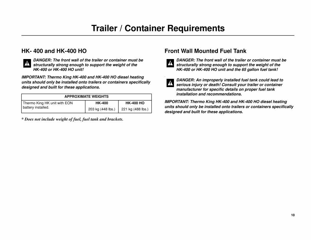
Trailer / Container Requirements
HK- 400 and HK-400 HO
IMPORTANT: Thermo King HK-400 and HK-400 HO diesel heating
units should only be installed onto trailers or containers specifically
designed and built for these applications.
* Does not include weight of fuel, fuel tank and brackets.
Front Wall Mounted Fuel Tank
-
IMPORTANT: Thermo King HK-400 and HK-400 HO diesel heating
units should only be installed onto trailers or containers specifically
designed and built for these applications.
DANGER: The front wall of the trailer or container must be structurally strong enough to support the weight of the HK-400 or HK-400 HO unit!
APPROXIMATE WEIGHTS
Thermo King HK unit with EON
battery installed.
HK-400
203 kg (448 lbs.)
HK-400 HO
221 kg (488 lbs.)
DANGER: The front wall of the trailer or container must be structurally strong enough to support the weight of the HK-400 or HK-400 HO unit and the 65 gallon fuel tank!
DANGER: An improperly installed fuel tank could lead to serious injury or death! Consult your trailer or container manufacturer for specific details on proper fuel tank installation and recommendations.

11
Trailer / Container Requirements

12
Mounting Bolt Specifications and Installation Requirements
Mounting Bolts Specifications
NOTE: Mounting hardware to be supplied by installer.
• Use Metric M12 x 1.75 pitch class 8.8 (1/2 in.-13 UNC - 2B Rolled
thread grade 5), medium carbon steel bolts and locking nuts.
• All hardware must be zinc plated with dichromate finish.
Mounting Bolt Installation Requirements
NOTE: The location of the unit mounting bolts in the trailer front wall
is critical to proper unit installation.
• A gasket sealing surface of 76.2 mm (3.00 in.) wide all around the
trailer wall opening must be free from rivets or bolt heads and flat
within 6.5 mm (.25 in.)
• All mounting bolts must be square with the front wall and securely
fastened to the trailer wall in such a manner to allow the mounting nuts
be torqued to 82 N•m (60 ft. lbs.) from outside the trailer.
• Mounting bolts are to extend 57.2 mm (2.25 in.) beyond the front wall
(Detail I).
• Surface of all mounting bolts are to be flat within 2.5 mm (0.10 in.).
DANGER: The use of mounting bolts other than those specified could result in severe damage to equipment, void the warranty or cause personal injury or death!
DANGER: Four mounting bolts must be installed to properly secure the unit to the trailer front wall! Failure to do so could result in severe damage to equipment, void the warranty or cause personal injury or death!

13
Mounting Bolt Specifications and Installation Requirements
14
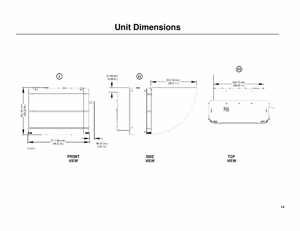
Unit Dimensions

15
BLANK PAGE

16
Battery Selection Guide
Refer to Service Bulletin T&T 446 for more information regarding Battery Selection and Maintenance.
IMPORTANT: The specified battery, electrical wiring and electronic
controls were designed to operate and maintain only the Thermo
King refrigeration system and factory authorized Thermo King
options.
Trailer units are designed for one 12 volt, Group 31 battery supplied by the
installer.
The battery must be suitable for deep cycling, heavy duty and rated with a
minimum of 95 amp/hr.
NOTE: See following table for Thermo King approved batteries.
Refer to Service Bulletin T&T 446 for more information regarding
Battery Selection and Maintenance.
CAUTION: Do not connect other manufacturer’s equipment or accessories to the Thermo King unit! This could result in severe damage to equipment and void the warranty!
BATTERY APPLICATION TABLE
750 CCA Wet Cell
Thermo King ReliaMax 750S
P/N 203-731 Threaded Stud
P/N 203-730 SAE Post
925 CCA Wet Cell
Thermo King ReliaMax 925N
P/N 203-733 Threaded Stud
P/N 203-732 SAE Post
1150 CCA Dry Cell (AGM)
Thermo King EON
P/N 203-550 Threaded Stud
P/N 203-551 SAE Post
• Wet Cell Technology
• Better suited for warmer climates
• Less cranking power at low
ambient temperatures
• 18-24 month expected life *see
note below
• Choose for southern climates
• Wet Cell Technology
• Better suited for colder climates
• High cranking power at low
ambient temperatures
• 18-24 month expected life *see
note below
• Choose for northern climates
• Dry Cell (AGM) Technology
• Better suited for all applications
• High cranking power at lower
ambient temperatures
• Suited for extreme temperatures
• Best for high cycling applications
(Cycle-Sentry use)
• 5-7 year expected life
* NOTE: Wet cell battery life and maintenance requirements are determined by the operating environment and the
charge/discharge rate (cycles) while the battery is in service. Higher ambient temperatures and frequent discharges
will shorten a wet cell battery’s overall life expectancy and increase maintenance requirements.

17
Group 31 Battery Dimensions
Lug Connections Threaded Stud Connections

18
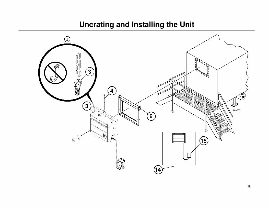
Uncrating and Installing the Unit
Uncrating the Unit
To avoid unnecessary damage to your unit, place the crated unit near the
trailer prior to its removal.
1. Carefully remove top boards of the crate.
2. Remove installation kit boxes and any other loose components from
rear of unit.
3. Attach two forged lifting eyebolts (1/2-13 UNC) into the thread holes
located on top of unit (Detail I).
4. Attach lifting device to eyebolts and slightly raise unit.
5. Remove hardware holding unit to crate.
Installing the Unit
Optional Zero Cube Installation
A zero cube installation kit is available from your Thermo King Dealer.
The kit consists of a insulated collar that positions the HK unit outside the
cargo area of the trailer.
6. Loosen each lifting plate bolt located on the collar, rotate the lifting
plates 180 degrees and retighten bolts.
7. Attach a lifting device to the lifting plates and raise the collar into
position at the rear of the unit with the gasket surface facing the trailer
opening.
8. Secure the collar to the rear of the unit with appropriate hardware and
tighten securely.
9. Unbolt and remove the lifting plates from the collar. Reinstall only the
bolts onto the collar.
10. Continue by following steps #11-15 below.
Standard Unit Installation
11. Lift the HK unit and position it in the trailer opening.
12. With the HK unit access door open, align the four mounting holes with
the mounting bolts.
13. Attach washer and elastic stop nuts (Nylock) and torque to 82 N•m (60
ft. lbs.).
14. Route the drain hose straight down and past the bottom of the trailer
and secure with supplied clamps and screws. Be sure not to pinch the
drain hose closed when routing and installing clamps.
15. Install the control box in a easily accessible location on the front of the
trailer wall without interfering with the operation of the trailer.
DANGER: Do not use a forklift to install the unit! This could result in severe damage to the equipment, void the warranty or cause personal injury or death!
WARNING: Use only locking hooks to safely lift the unit! Failure to use locking hooks could result in severe damage to the equipment, void the warranty or cause personal injury or death! (Detail I).
19
Uncrating and Installing the Unit
20
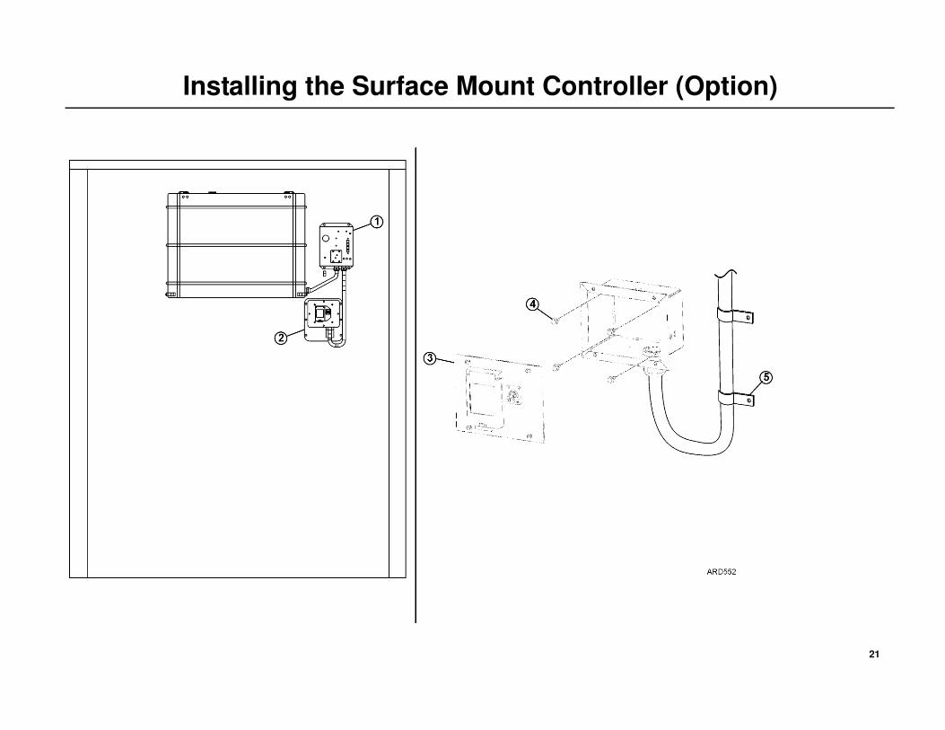
Installing the Surface Mount Controller (Option)
NOTE: The installation views shown are for reference only. The
actual locations chosen for installing the main control box and the
surface mount controller may vary per your specific application.
Installation
1. Install the main control box securely to the trailer wall with appropriate
mounting hardware.
2. Position the surface mount controller directly under the main control
box while providing a drip loop as shown and mark the location.
3. Remove the front cover from the surface mount controller.
4. Drill four appropriate size mounting holes inside the four corners of the
box and mount it securely to the trailer with appropriate mounting
hardware.
5. Reinstall the front cover and route and secure the power cable to the
front wall of the trailer with clamps.
21
Installing the Surface Mount Controller (Option)

22
Installing the Flush Mount Controller (Option)
NOTE: The installation views shown are for reference only. The
actual locations chosen for installing the main control box and the
flush mount controller may vary per your specific application.
Installation
1. Install the main control box securely to the trailer wall with appropriate
mounting hardware.
2. Position the flush mount controller directly under the main control box
while providing a drip loop as shown and mark the location.
3. Remove the front cover from the flush mount controller.
4. Measure, mark and cut out an appropriate size hole in the trailer wall
for the controller box pocket.
5. From outside the trailer, install the controller box pocket into the trailer
wall with appropriate mounting hardware.
6. From inside the trailer, install the insulation box into the trailer wall
with appropriate size mounting hardware.
7. Once the controller pocket box and the insulation box are installed, use
the supplied holes in the pocket box to fill the air gap with insulating
foam (supplier supplied).
8. Reinstall the front cover and route and secure the power cable to the
front wall of the trailer with clamps.

23
Installing the Flush Mount Controller (Option)
Controller Box Pocket
(mounted outside trailer)
Insulation Box
(mounted inside trailer)

24
Installing the Fuel Tank - Aluminum, 22'' dia. 30 & 50 Gallon - (Option)
Installed onto Trailers with Standard Cross Member Spacing
Open Style Tank Mounting Bracket - New fuel tank mounting kits were
released November 1, 2008. Factory Kit 701635 and Aftermarket Kit
90-398 contain a new open style fuel tank mounting bracket. This new
mounting bracket can be used to install either a 30 or 50 gallon, 22''
diameter fuel tanks onto a typical trailer with standard crossmember
spacing of 6'', 8'', 10'' or 12''.
• Trailers with non-standard crossmember spacing of 9'', 15'' and 16'' will
require the additional components found in Kit 701658 (90-399) to
complete the installation.
• These new kits can not be used to install a 75, 90, 110 or 120 gallon,
22'' diameter fuel tanks. Those tanks require Kit 710278 (90-121).
• DO NOT substitute any components from Kits 701635 (90-398) and
701658 (90-399) with any previously supplied fuel tank mounting kits
as they are not interchangeable.
• Kits 701635 (90-398) and 701658 (90-399) are specifically designed to
install a 30 or 50 gallon fuel tank in a hanging position under a trailer
attached to the floor crossmembers. Substitutions are not acceptable!
A. Fuel Tank Position
• Thermo King recommends the fuel tank be mounted 203.2 mm
(8.00 in.) under the trailer as shown. Otherwise, the OEM or
installer is responsible to ensure the fuel tank position meets or
exceeds DOT or Federal Highway regulations, when applicable.
B. Tank Strap Position
• 30 Gallon Tanks - Fuel tank straps must be positioned 381 mm
(15.00 in.) apart as shown.
• 50 Gallon Tanks - Fuel tank straps must be positioned 673 mm
(25.50 in.) apart as shown.
C. Rubber Strips and Pads
• Rubber strips must be properly installed on both the mounting
bands and the rubber pads must be installed onto the underside of
the hanger assemblies to prevent metal to aluminum contact.
D. Mounting Hardware
• Grade 5 mounting hardware is supplied. Substitutions are not
acceptable!
• All mounting hardware must be properly installed and torqued to
the specifications listed.
DANGER: An improperly installed fuel tank could lead to serious injury or death! Consult your trailer manufacturer for specific details on proper fuel tank installation and recommendations.
CAUTION: The trailers crossmembers must be strong enough to safely support the combined weight of the mounting hardware, fuel tank and fuel.
Fuel Tank Capacity Combined Total Weight
30 Gallon Diesel 142 KG (313 lbs.)
50 Gallon Diesel 214 KG (471 lbs.)
Hardware Size Torque Specifications
3/8-16 Grade 5 42 N•m (31 ft-lb)
1/2 -13 Grade 5 81 to 88 N•m (60-65 ft-lb)
1/2'' T-bolts 48 N•m (35 ft-lb.)

25
Installing the Fuel Tank - Aluminum, 22'' dia. 30 & 50 Gallon - (Option)
Standard crossmember spacing shown. For other crossmember spacing, refer to TK-54238-2-IM.
Non-standard crossmember spacing of 9'', 15'' and 16'' also requires Kit 701658 (90-399)
Tank can be mounted on
either side of trailer.
NOTE: Location of mounting holes may change if
other trailer options are added.
Cross Member Spacing
50 Gallon Fuel Tank Shown

26
Installing the Fuel Tank - Aluminum, 22'' dia. 30 & 50 Gallon - (Option)
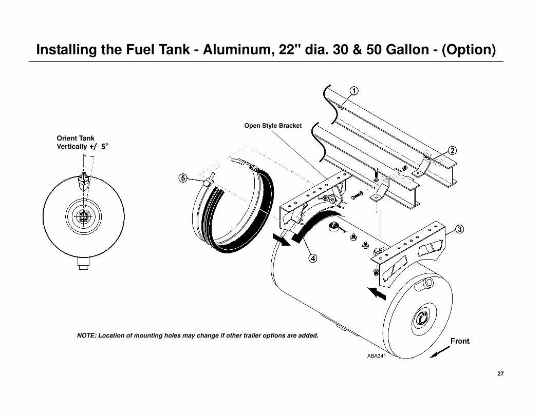
Fuel Tank Installation
NOTE: Location of mounting holes may change if other trailer
options are added.
1. Locate the existing sets of 10.3 mm (.406'' dia.) pre-punched holes in
the crossmembers. See note above.
2. Align the two holes of each hanger bracket with the holes in the
crossmember and secure with two, 3/8-16 screws, washers and locking
nuts. Torque the hardware to 42 N•m (31 ft-lb).
3. Install each hanger assembly (facing each other as shown) onto the
hanger brackets with 1/2-13 screws, washers and locking nuts. Torque
the hardware to 81 to 88 N•m (60-65 ft-lb).
4. Clean the underside of each hanger assembly and install the self-
adhesive rubber pads.
5. Loosely install the tank straps t-bolts onto the hanger assemblies with
1/2'' washers and locking nuts. Verify the rubber strips are properly
installed on the mounting bands.
6. Install the fuel tank into the straps with the tank positioned vertically
within plus or minus 5 degrees and tighten the tank straps to
48 N•m (35 ft-lb).
27
Installing the Fuel Tank - Aluminum, 22'' dia. 30 & 50 Gallon - (Option)
Open Style Bracket
Orient Tank Vertically
NOTE: Location of mounting holes may change if other trailer options are added.
28
Installing the Fuel Tank - Aluminum, L-Shaped, 65 Gallon - (Option)
Important Fuel Tank Installation InformationNOTE: These instructions are written exclusively for, and are limited
to, the installation of the aluminum L-Shaped 65 gallon fuel tank,
positioned directly under a Thermo King HK heating unit, and
mounted onto the front wall of a trailer or intermodal container
designed specifically for this application. All other installations are
the responsibilities of the installer.
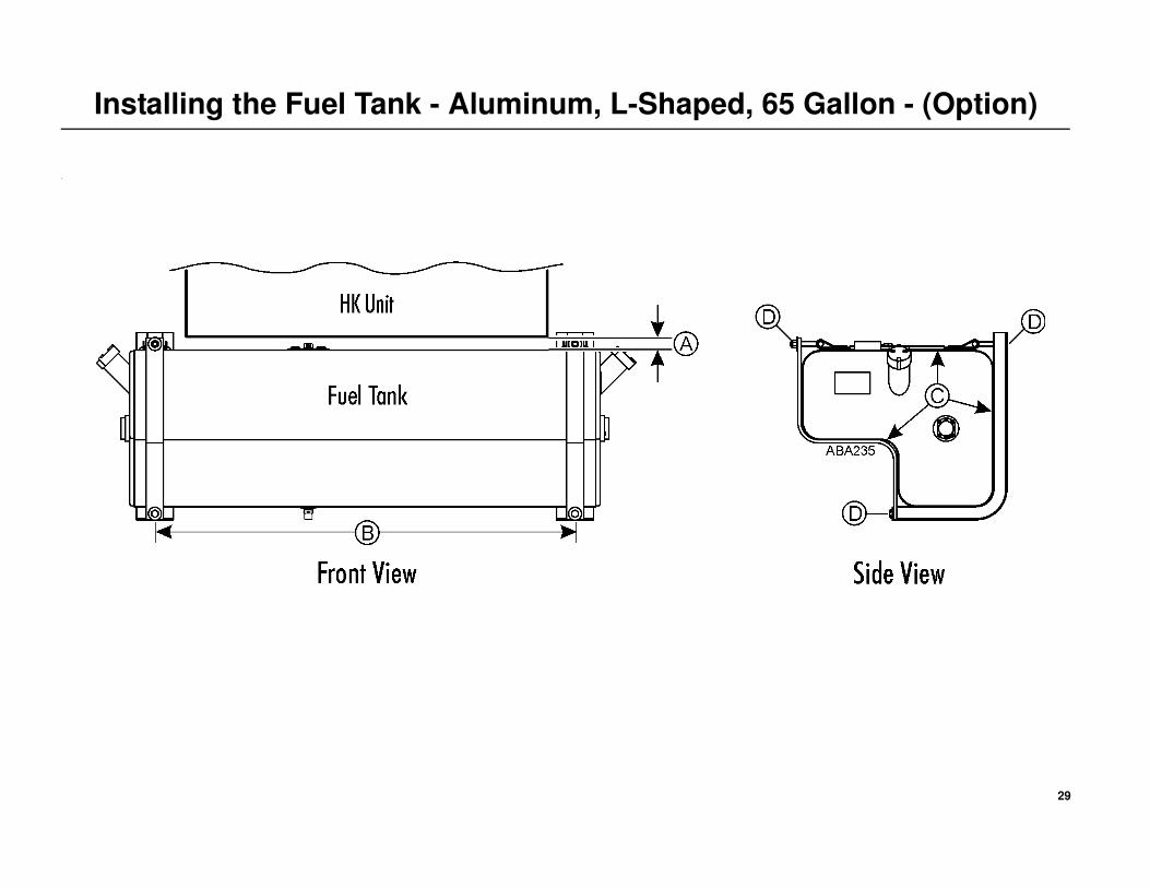
A. FUEL TANK POSITION
• Thermo King recommends the fuel tank be centered directly under
the HK heating unit.
B. TANK STRAP POSITION
• Fuel tank mounting brackets and support straps must be positioned
1225 mm (48.25 in.) apart to properly support the weight of the
tank and fuel.
• The tank straps must fit into the strap guides located on the top of
the fuel tank.
C. RUBBER STRIPS AND PADS
• Rubber strips must be properly installed on the mounting brackets,
and mounting bands to prevent metal to aluminum contact.
D. MOUNTING HARDWARE
• Grade 5 mounting hardware is supplied to secure the tank to the
mounting brackets.
• Mounting hardware to secure the complete fuel tank and mounting
bracket assembly onto the trailer or container is to be supplied by
the installer and must be 1/2-13 UNC (rolled thread), Medium
Carbon Steel (Grade 5 or better) with Zinc Plate and Dichromate
finish.
• All mounting hardware must be properly installed and torqued to
the specifications listed.
DANGER: An improperly installed fuel tank could lead to serious injury or death! The mounting hardware to secure the fuel tank and mounting brackets onto the front wall of the trailer or intermodal container is to be supplied by the installer and must be 1/2-13 UNC (rolled thread), Medium Carbon Steel (Grade 5 or better) with Zinc Plate and Dichromate finish. Additionally, the front wall of the trailer or intermodal container must be structurally strong enough to safely support the combined total weight of the HK heating unit, the fuel tank and mounting brackets and 65 gallons of diesel fuel (see chart below). Consult your trailer or intermodal container manufacturer for details regarding your specific installation.
APPROXIMATE WEIGHTS
Thermo King HK unit with EON
battery installed.
HK-400
203 kg (448 lbs.)
HK-400 HO
221 kg (488 lbs.)
Aluminum L-shaped fuel tank,
mounting brackets and hardware.
53.5 kg (118 lbs.) 53.5 kg (118 lbs.)
65 gallons of diesel fuel. 236 kg (520 lbs.) 236 kg (520 lbs.)
COMBINED TOTAL WEIGHT 492.5 kg (1086 lbs.) 510.5 kg (1126 lbs.)
29
Installing the Fuel Tank - Aluminum, L-Shaped, 65 Gallon - (Option)
.

30
Installing the Fuel Tank - Aluminum, L-Shaped, 65 Gallon - (Option)
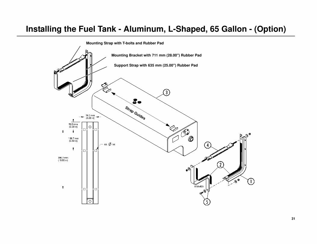
Fuel Tank Installation
1. Install the tank mounting brackets with six, (installer supplied) 1/2-13
screws, washers and locking nuts onto the front wall. Torque the
hardware to 81 to 88 N•m (60-65 ft-lb.).
2. Clean the inside surfaces of the mounting brackets and support straps.
Install the 711 mm (28.00') long rubber strips onto the mounting
brackets and the 635 mm (25.00'') long rubber strips onto the support
straps.
3. Install and center the tank onto the mounting brackets.
4. Install the mounting straps with T-bolts onto the upper holes of the
mounting bracket with the supplied 1/2'' washers and locking nuts.
Verify the rubber strips are properly installed on the mounting straps
and straps are aligned with the strap guides on the top of the tank.
Leave the nuts finger-tight on the threads.
5. Install the support straps to the lower mounting holes of each mounting
bracket with the supplied 1/2-13 x 1.50'' long bolts, flat washers and
locking nuts. Leave the nuts finger-tight on the threads.
6. Tighten the lower nuts first to 44.5 N•m (33 ft-lb.) or until 2 full threads
are exposed through the locking material of the nut, then tighten the
upper nuts to 44.5 N•m (33 ft-lb.).
NOTE: At least two full threads must be exposed after 44.5 N•m
(33 ft-lb.) is applied. If not, tighten the nuts until two full threads
project through the locking material of the nuts.
IMPORTANT: Do not over tighten the mounting hardware or damage
to the tank will result.
31
Installing the Fuel Tank - Aluminum, L-Shaped, 65 Gallon - (Option)
Mounting Strap with T-bolts and Rubber Pad
Mounting Bracket with 711 mm (28.00'') Rubber Pad
Support Strap with 635 mm (25.00'') Rubber Pad
Strap Guides

32
Installing the Fuel Tank - Steel, Rectangle, 65 Gallon - (Option)
Important Fuel Tank Installation InformationNOTE: These instructions are written exclusively for, and are limited
to, the installation of the 65 gallon steel fuel tank, positioned directly
under a Thermo King HK heating unit, and mounted onto the front
wall of a trailer or intermodal container designed specifically for this
application. All other installations are the responsibilities of the
installer.
A. FUEL TANK POSITION
• Thermo King recommends the fuel tank be centered directly under
the HK heating unit.
B. TANK STRAP POSITION
• L-brackets and support straps must be positioned 1225 mm
(48.25 in.) apart to properly support the weight of the tank and fuel.
C. RUBBER PADS AND STRIPS
• Rubber pads and strips must be properly installed on the L-brackets
and support straps to prevent metal to metal contact.
D. MOUNTING HARDWARE
• Grade 5 mounting hardware is supplied to secure the tank to the
L- brackets.
• Mounting hardware to secure the complete fuel tank and mounting t
assembly onto the trailer or container is to be supplied by the
installer and must be 1/2-13 UNC (rolled thread), Medium Carbon
Steel (Grade 5 or better) with Zinc Plate and Dichromate finish.
• All mounting hardware must be properly installed and torqued to
the specifications listed.
DANGER: An improperly installed fuel tank could lead to serious injury or death! The mounting hardware to secure the fuel tank and mounting brackets onto the front wall of the trailer or intermodal container is to be supplied by the installer and must be 1/2-13 UNC (rolled thread), Medium Carbon Steel (Grade 5 or better) with Zinc Plate and Dichromate finish. Additionally, the front wall of the trailer or intermodal container must be structurally strong enough to safely support the combined total weight of the HK heating unit, the fuel tank and mounting brackets and 65 gallons of diesel fuel (see chart below). Consult your trailer or intermodal container manufacturer for details regarding your specific installation.
APPROXIMATE WEIGHTS
Thermo King HK unit with EON
battery installed.
HK-400
203 kg (448 lbs.)
HK-400 HO
221 kg (488 lbs.)
Steel, rectangle fuel tank,
mounting brackets and
hardware.
89.4 kg (197 lbs.) 89.4 kg (197 lbs.)
65 gallons of diesel fuel. 236 kg (520 lbs.) 236 kg (520 lbs.)
COMBINED TOTAL WEIGHT 528.4 kg (1165 lbs.) 546.4 kg (1205 lbs.)

33
Installing the Fuel Tank - Steel, Rectangle, 65 Gallon - (Option)
34
Installing the Fuel Tank - Steel, Rectangle, 65 Gallon - (Option)
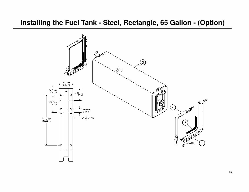
Fuel Tank Installation
1. Install the L-brackets with six, (installer supplied) 1/2-13 screws,
washers and locking nuts onto the front wall of the container or trailer.
Torque the hardware to 81 to 88 N•m (60-65 ft-lb.).
2. Clean the inside surfaces of the L-brackets and install the 710 mm
(27.95 in.) self-adhesive rubber pads. Slide the 813 mm (32.00 in.)
rubber strips onto the support straps.
3. Position and center the tank onto the L-brackets.
4. Install the T-bolts on the support straps into the upper and lower holes
of the L-brackets with the supplied 1/2'' washers and locking nuts.
Verify the rubber pads and strips are properly positioned on the L-
brackets and straps to prevent any metal to metal contact before hand
tightening the mounting hardware. Leave the nuts finger-tight on the
threads.
5. Tighten the lower nuts first to 44.5 N•m (33 ft-lb.) or until 2 full threads
are exposed through the locking material of the nut, then tighten the
upper nuts to 44.5 N•m (33 ft-lb.).
NOTE: At least two full threads must be exposed after 44.5 N•m
(33 ft-lb.) is applied. If not, tighten the nuts until two full threads
project through the locking material of the nuts.
IMPORTANT: Do not over tighten the mounting hardware or damage
to the tank will result
35
Installing the Fuel Tank - Steel, Rectangle, 65 Gallon - (Option)

36
Installing the Fuel Pump and Fuel Lines
FOR UNDER CHASSIS FUEL TANKS
Installation Recommendations
• All fuel lines should be routed in a protective housing with no kinks
and sharp bends.
• Rubber grommets must be used when routing fuel lines through
holes in metal.
• Secure all fuel lines with provided clamps.
• Remove plastic cap from the fuel vent and point the outlet towards
the rear of the trailer.
Installing the Fuel Pump and Fuel Lines
1. Install the fuel pump and bracket as low as possible to provide rapid
pump priming.
2. Route the fuel supply line from the fuel filter located inside the unit,
down to the fuel pump and then to the fuel pickup tube on the fuel tank.
Install fuel line connectors (provided in installation kit), cut end of fuel
line at a 45 degree angle and insert into fuel pickup tube until it is
38.1 mm (1.50 in.) from the bottom of the tank and tighten securely.
3. Route the fuel return line from the fuel filter located inside the unit
down to the fuel tank return fitting. Attach fuel line connectors and
tighten securely.
4. Route the electrical harness from the unit to the fuel pump and attach to
the fuel pump connector. The connector must be installed out of road
spray area.
NOTE: Add sufficient amount of fuel (1/4 tank) to allow the unit to run
for 8 to 12 hours during engine break-in and pre-delivery procedures.
DANGER: Leaking fuel lines could cause a fire resulting in death or serious injury! All fuel line fittings must be tight and leak free!
DANGER: Do not route fuel lines with battery cables or electrical wires, as this could cause a fire!

37
Installing the Fuel Pump and Fuel Lines
FUEL FILTER LOCATED INSIDE UNIT FUEL PUMP LOCATED OUTSIDE TRAILER
FOR UNDER CHASSIS FUEL TANKS
38
Installing the Fuel Pump and Fuel Lines
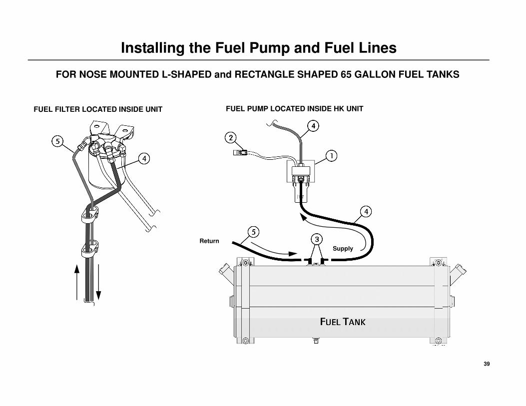
FOR NOSE MOUNTED L-SHAPED and RECTANGLE SHAPED 65 GALLON FUEL TANKS
Fuel Pump Installation
1. Install the fuel pump and bracket inside the unit next to the battery box
with 1/4-20 screws, flat washers and locking nuts. Tighten hardware
securely.
2. Route and attach the fuel pump harness to the fuel pump.
Fuel Line Installation
3. Remove the protective plugs from each of the fuel fittings and install
the fuel line supply and return line fittings securely.
4. FUEL SUPPLY - Route fuel lines from:
• Supply fitting on the fuel filter to the top outlet fitting of the fuel
pump.
• Side inlet fitting on the fuel pump to the fuel tank fitting.
• Tighten all fuel line fittings securely.
5. FUEL RETURN - Route fuel line from:
• Return line fitting from the fuel filter to the fuel tank fitting.
• Tighten all fuel line fittings securely.
6. Secure all fuel lines adequately with cable ties or clamps.
7. Remove the plastic cap from the fuel vent and point it towards the rear
of the unit.
NOTE: Add sufficient amount of fuel (1/4 tank) to allow the unit to
operate.
8. Operate the unit and check all fuel line fittings for leaks.
DANGER: Leaking fuel lines could cause a fire resulting in death or serious injury! All fuel line fittings must be tight and leak free!
DANGER: Do not route fuel lines with battery cables or electrical wires, as this could cause a fire!
39
Installing the Fuel Pump and Fuel Lines
FOR NOSE MOUNTED L-SHAPED and RECTANGLE SHAPED 65 GALLON FUEL TANKS
FUEL FILTER LOCATED INSIDE UNIT FUEL PUMP LOCATED INSIDE HK UNIT
Supply
Return

40
Installing the Battery
Installing the Battery 1. Open unit door to access battery tray.
2. Install battery into tray and secure with hold down bracket, bolts, lock
washers and flat washers.
• Hand tighten both bolts and then torque to 6.8 N•m (60 in-lb).
DO NOT over tighten hardware as this may crack or distort the
battery!
3. Install positive + battery cable on the positive battery post first to
minimize accidental electrical shorting.
4. Install negative - battery cable on negative battery post second to
minimize accidental electrical shorting.
5. Close and secure unit door.
CAUTION: Set all electrical controls to the OFF position before connecting the battery to prevent the unit from starting!
CAUTION: Always wear protective clothing, gloves and eye wear when handling and installing batteries!
CAUTION: Cover battery terminals to prevent accidental shorting during battery installation!
CAUTION: Do not route battery cables together with fuel lines as this could cause a fire!
CAUTION: All battery connections must be clean and tightly secured.

41
Installing the Battery
42
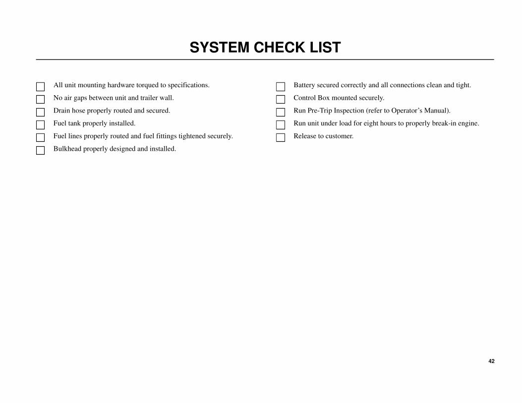
SYSTEM CHECK LIST
All unit mounting hardware torqued to specifications.
No air gaps between unit and trailer wall.
Drain hose properly routed and secured.
Fuel tank properly installed.
Fuel lines properly routed and fuel fittings tightened securely.
Bulkhead properly designed and installed.
Battery secured correctly and all connections clean and tight.
Control Box mounted securely.
Run Pre-Trip Inspection (refer to Operator’s Manual).
Run unit under load for eight hours to properly break-in engine.
Release to customer.

43