installation manual - mike granby's website sl-30... · installation manual ... • tunes to...
TRANSCRIPT

Apollo
Model SL30 NAV/COMM
Installation Manual
November 1999 560-0404-00

1999 by UPS Aviation Technologies Inc. All rights reserved.Printed in the USA
No part of this document may be transmitted, reproduced, or copied in any form or by any meanswithout the prior written consent of UPS Aviation Technologies Inc. Due to UPS AviationTechnologies’s commitment to constantly improve the quality and performance of our products,information contained in this document is subject to change without notice.
UPS Aviation Technologies, Apollo, and Flybrary are registered trademarks of UPS AviationTechnologies Inc.
UPS Aviation Technologies Inc. 2345 Turner Rd. SEPO Box 13549 Salem, OR 97302Salem, OR 97309 USA
Phone (503)581-81011-800-525-6726In Canada 1-800-654-3415FAX (503)364-2138

HISTORY OF REVISIONS
Revision Date Description-- 11/16/99 Initial release (EN6278).
IMPORTANT NOTE“The conditions and tests required for TSO approval of this article are minimum performancestandards. It is the responsibility of those desiring to install this article on or within a specifictype or class of aircraft to determine that the aircraft operating conditions are within TSOstandards. The article may be installed only if further evaluation by the applicant documents anacceptable installation and is approved by the Administrator.” Follow installationrecommendations as noted in AC20-67B, Airborne VHF Communications EquipmentInstallations.
Source: FAA TSO-C34e, TSO-C36e, TSO-C37d, TSO-C38d, TSO-C40c, TSO-C66c, and TSO-C128.
ORDERING INFORMATIONTo receive additional copies of this publication, order part # 560-0404-00, Apollo SL30 NAV/COMM Installation Manual.
REFERENCE PUBLICATIONSFollowing are other publications referenced in this guide.Apollo SL30 NAV/ COMM Operation Manual, order part # 560-0403-00.

NOTES

Table of Contents
Apollo SL30 Installation Manual i
TABLE OF CONTENTS
SECTION 1 - INTRODUCTION .............................................................................................1ABOUT THIS MANUAL..................................................................................................................1APOLLO SL30 DESCRIPTION.........................................................................................................1FEATURES....................................................................................................................................2
GENERAL FEATURES ...........................................................................................................................................2NAVIGATION RADIO FEATURES............................................................................................................................2COMM RADIO FEATURES .....................................................................................................................................3PHYSICAL SPECIFICATIONS ..................................................................................................................................3NAV RADIO PERFORMANCE SPECIFICATIONS.......................................................................................................3COMM RADIO PERFORMANCE SPECIFICATIONS .....................................................................................................3
SYSTEM INTERFACES....................................................................................................................4NAVIGATION RECEIVER.......................................................................................................................................4COMM TRANSCEIVER ..........................................................................................................................................4SERIAL INTERFACE..............................................................................................................................................4
REGULATORY COMPLIANCE .........................................................................................................4UNPACKING THE EQUIPMENT........................................................................................................5PACKAGE CONTENTS....................................................................................................................5OTHER REQUIRED MATERIALS .....................................................................................................6SPECIAL TOOLS REQUIRED ...........................................................................................................6LICENSE REQUIREMENTS..............................................................................................................7
SECTION 2 - INSTALLATION...............................................................................................9PRE-INSTALLATION INFORMATION ...............................................................................................9INSTALLATION OVERVIEW............................................................................................................9INSTALLATION CONSIDERATIONS..................................................................................................9
MOUNTING CONSIDERATIONS..............................................................................................................................9MINIMUM SYSTEM CONFIGURATION ....................................................................................................................9
EQUIPMENT MOUNTING .............................................................................................................10ELECTRICAL CONNECTIONS........................................................................................................12
POWER ............................................................................................................................................................. 12AVIONICS OUTPUTS .......................................................................................................................................... 12SERIAL INTERFACE............................................................................................................................................ 12SPEAKER AND HEADPHONE OUTPUTS ................................................................................................................. 12MICROPHONE INPUTS ........................................................................................................................................ 13TRANSMIT KEY INPUT ....................................................................................................................................... 13INTERCOM SELECTOR SWITCH ........................................................................................................................... 13REMOTE FLIP/FLOP INPUT ................................................................................................................................. 13
ANTENNA INSTALLATION AND CONNECTIONS .............................................................................13COMM AND NAV ANTENNAS.............................................................................................................................. 13USE OF SPLITTER AND COMBINER ...................................................................................................................... 14
EQUIPMENT INTERFACE..............................................................................................................15LIMITATIONS ON USING A COMPOSITE SIGNAL............................................................................28POST INSTALLATION CHECKOUT.................................................................................................28
MOUNTING / WIRING CHECK............................................................................................................................. 28SETUP AND CHECKOUT ...................................................................................................................................... 28FINAL SYSTEM CHECK ...................................................................................................................................... 32
INSTRUCTIONS FOR CONTINUED AIRWORTHINESS .......................................................................35

Table of Contents
ii Apollo SL30 Installation Manual
SECTION 3 - SPECIFICATIONS......................................................................................... 37ELECTRICAL.............................................................................................................................. 37PHYSICAL ................................................................................................................................. 37ENVIRONMENTAL...................................................................................................................... 37AVIONICS OUTPUTS................................................................................................................... 38NAV RECEIVER PERFORMANCE ................................................................................................ 39
VOR................................................................................................................................................................ 39LOCALIZER ....................................................................................................................................................... 39GLIDESLOPE ..................................................................................................................................................... 40OBS RESOLVER................................................................................................................................................ 40COMPOSITE OUTPUT ......................................................................................................................................... 40
COMM RECEIVER PERFORMANCE .............................................................................................. 41COMM TRANSMITTER PERFORMANCE........................................................................................ 41INTERCOM PERFORMANCE ........................................................................................................ 42CONTROL INPUTS ...................................................................................................................... 42ANTENNA REQUIREMENTS......................................................................................................... 42
COMM ANTENNA .............................................................................................................................................. 42NAV ANTENNA................................................................................................................................................ 42
SERIAL INTERFACE.................................................................................................................... 43REAR CONNECTOR PINOUT........................................................................................................ 43
SECTION 4 - LIMITATIONS............................................................................................... 45INSTALLATION........................................................................................................................... 45OPERATIONAL........................................................................................................................... 45
APPENDIX A - TROUBLESHOOTING .............................................................................. 47CONTACTING THE FACTORY FOR ASSISTANCE ............................................................................ 47
APPENDIX B - PERIODIC MAINTENANCE..................................................................... 49VOR CHECKS ........................................................................................................................... 49EQUIPMENT CALIBRATION......................................................................................................... 49
REFERENCE OSCILLATOR (COMM ONLY)............................................................................................................ 49CLEANING THE FRONT PANEL .................................................................................................... 49
APPENDIX C - ENVIRONMENTAL QUALIFICATIONS ................................................ 51
APPENDIX D - ACCESSORIES........................................................................................... 53FROM UPS AVIATION TECHNOLOGIES ....................................................................................... 53
APPENDIX E - SERIAL INTERFACE SPECIFICATIONS ............................................... 55INPUT COMMANDS .................................................................................................................... 55OUTPUT MESSAGES ................................................................................................................... 55DATA FORMAT.......................................................................................................................... 56MESSAGE FORMATS .................................................................................................................. 56MESSAGE DEFINITIONS.............................................................................................................. 57
INPUT MESSAGES .............................................................................................................................................. 57REMOTE VOR LIST........................................................................................................................................... 58REMOTE LOCALIZER LIST .................................................................................................................................. 59REQUEST DATA OUTPUT ................................................................................................................................... 61

Table of Contents
Apollo SL30 Installation Manual iii
SET ACTIVE VOR/LOC FREQUENCY AND RECEIVER FUNCTION .......................................................................... 62SET STANDBY VOR/LOC FREQUENCY AND RECEIVER FUNCTION ....................................................................... 62SET STANDBY COMM FREQUENCY................................................................................................................... 63SET NAV AUDIO MODE.................................................................................................................................... 64SET OMNI-BEARING SELECT (OBS) VALUE........................................................................................................ 64DME SENSOR INPUT ......................................................................................................................................... 64
OUTPUT MESSAGES....................................................................................................................65RESET STATUS .................................................................................................................................................. 65CDI, GSI, AND RELATED FLAGS........................................................................................................................ 65DECODED OBS SETTING ................................................................................................................................... 66RADIAL FROM ACTIVE VOR.............................................................................................................................. 67RADIAL FROM STANDBY VOR........................................................................................................................... 67DECODED STATION IDENTIFIER ......................................................................................................................... 68COMMUNICATIONS ERROR ................................................................................................................................ 68NAV RECEIVER STATUS ................................................................................................................................... 69NAV AUDIO MODE .......................................................................................................................................... 69NAV MICROCONTROLLER SOFTWARE VERSION................................................................................................. 69NAV DSP SOFTWARE VERSION ........................................................................................................................ 70COMM TRANSCEIVER STATUS............................................................................................................................ 70COMM SOFTWARE VERSION .............................................................................................................................. 71

Table of Contents
iv Apollo SL30 Installation Manual
LIST OF TABLESTABLE 1 - PACKAGE CONTENTS................................................................................................... 5TABLE 2 - COMM INTERFACE CONNECTOR PINOUT .................................................................... 43TABLE 3 - REAR PANEL CONNECTOR PINOUT ............................................................................ 44TABLE 4 - TROUBLESHOOTING GUIDE........................................................................................ 47TABLE 5 - DATA OUTPUT REQUESTS.......................................................................................... 61
LIST OF ILLUSTRATIONSFIGURE 1 - SL30 FRONT PANEL................................................................................................... 2FIGURE 2 - MOUNTING FRAME ASSEMBLY ................................................................................. 11FIGURE 3 - CABLE ROUTING ...................................................................................................... 11FIGURE 4 - REAR COAX CONNECTOR ASSEMBLY ....................................................................... 14FIGURE 5 - SL30 COMM WIRING DIAGRAM ............................................................................... 16FIGURE 6 - SL30 COMM TYPICAL AUDIO PANEL CONNECTIONS................................................. 17FIGURE 7 - SL30 NAV REQUIRED CONNECTIONS ...................................................................... 18FIGURE 8 – SL30 NAV OPTIONAL CONNECTIONS...................................................................... 18FIGURE 9 - SL30 NAV TO MID-CONT MD200-306/307............................................................. 19FIGURE 10 - SL30 NAV TO MID-CONT MD200-302/303 CONNECTIONS.................................... 20FIGURE 11 - SL30 NAV AND ACU TO MID-CONT MD200-306/307 .......................................... 21FIGURE 12 - SL30 NAV TO STEC IND-351A CONNECTIONS .................................................... 22FIGURE 13 - SL30 NAV TO BENDIX/KING KN72/203/204/208/208A/209/209A WIRING ........... 23FIGURE 14 - SL30 NAV TO BENDIX/KING KI202/206/525A/KPI552 WIRING ............................ 24FIGURE 15 - SL30 NAV TO SANDEL DISCRETE CONNECTIONS ................................................... 25FIGURE 16 - SL30 NAV TO SANDEL SN3308 CONVERTER CONNECTIONS.................................. 26FIGURE 17 - SL30 TO COLLINS 331A-6P, 331A-9G AND SPERRY RD 550A, RD650 WIRING ..... 27FIGURE 18 - UNIT DIMENSIONS ................................................................................................. 38

Introduction
Apollo SL30 Installation Manual 1
SECTION 1 - INTRODUCTION
ABOUT THIS MANUALThis manual describes the installation of the Apollo SL30 Nav/Comm units. It is intended foruse by persons certified by the Federal Aviation Administration (FAA) to install aircraftnavigation devices. It includes installation and checkout procedures for the SL30 unit tostandards described in FAA advisory circulars AC 20-67B (for Comm).
Provides an introduction to the Apollo SL30 unit. TSO certification informationis also included in this section.
Includes installation and checkout procedures.
Includes complete specifications.
Includes limitations for the equipment and installation.
Includes troubleshooting information.
Includes periodic maintenance requirements.
Includes the environmental qualification form.
Includes information on accessories.
Includes serial data specifications.
APOLLO SL30 DESCRIPTIONThe Apollo SL30 includes a 760 channel VHF Comm transceiver and 200 channelVOR/LOC/GS navigation receiver with DME display.
The Apollo SL30 is a member of the Apollo slimline series which includes the SL10/15 AudioSelector Panels, SL40 Comm, SL50 GPS, SL60 GPS/Comm, and SL70 Transponder.
Section 1
Section 2
Section 3
Section 4
Appendix A
Appendix B
Appendix C
Appendix D
Appendix E

Introduction
2 Apollo SL30 Installation Manual
FEATURES
GENERAL FEATURES
• 32 character high-intensity alphanumeric LED display• Sunlight readable full alphanumeric display• Automatic display intensity• Back-lit buttons• 200 channel memory (stored alphabetically)• Remote frequency flip-flop input pin
NAVIGATION RADIO FEATURES
• 200 channel Nav with solid state DSP technology• VOR/Localizer and Glideslope receivers• Built-in VOR/Localizer converter• Frequency range: VOR 108.00 – 117.95 MHz
Localizer 108.00 – 111.95 MHzGlideslope 328.60 – 335.40 MHz
• Digitally decoded OBS setting• Manual selection of back course approach• Automatic display of station ID by decoding Morse code• Interfaces to most CDI (w/resolver), HSI, and autopilot systems• VOR receiver displays To or From radial of the active channel• VOR monitor displays From radial of the standby channel• Back course annunciator output• LOC enable annunciator output
Figure 1 - SL30 Front Panel

Introduction
Apollo SL30 Installation Manual 3
• Internal RF diplexor• Active and standby flip/flop frequencies• DME tuning an data display
COMM RADIO FEATURES
• 760 communications channels• Frequency range 118 to 136.975 MHz• Active and standby flip/flop frequencies• Volume control• Tunes to National Weather Service broadcasts• Transmit status indicator• Frequency monitor function (listens to standby while monitoring active)• Emergency channel menu• Squelch test function• Stuck Mic time-out• 12 watt audio amplifier• Includes two-place VOX intercom
PHYSICAL SPECIFICATIONS
• 1.3"(H) x 6.25" (W) x 10.5" (D)• Weight 2.25 lbs. (unit only)• Depth 11.452 inches (29.09cm) behind panel, including mounting frame and connectors
NAV RADIO PERFORMANCE SPECIFICATIONS
• Input voltage range 10 to 40 VDC• Operating temperature range –20ºC to +55ºC• Certified TSO C34e (Glideslope receive)• Certified TSO C36e (ILS Localizer receive)• Certified TSO C40c (VOR receive)• Certified TSO C66c (DME display)
COMM RADIO PERFORMANCE SPECIFICATIONS
• Input voltage range 10 to 40 VDC• Operating temperature range –20ºC to +55ºC• Transmit power 8 watts (Carrier Power)• Certified TSO C37d (Comm transmitting)• Certified TSO C38d (Comm receiving)• Certified TSO C128 (stuck mic)

Introduction
4 Apollo SL30 Installation Manual
SYSTEM INTERFACES
NAVIGATION RECEIVER
The SL30 can be installed in several configurations based upon individual requirements. Thisincludes with or without an external course deviation indicator. The CDI may be discrete,serial, or composite.
COMM TRANSCEIVER
For standalone installations, the Comm requires connections to:• a standard Comm antenna• a microphone (or microphones)• a speaker or headphone• power input
These items may be installed dedicated to the SL30 Comm, or by connection to an audio panel.The system can be configured to mix the NAV audio with the Comm audio if no external audiopanel is used.
SERIAL INTERFACE
• DME – Distance Measure Equipment• SL/GX – GPS products• MX – Multi-Function Display
REGULATORY COMPLIANCEThe Apollo SL30 is designed and tested to meet the following TSOs:
FAA TSO-C37d for Comm transmitFAA TSO-C38d for Comm receiveFAA TSO-C128 for unintentional transmission (stuck mic)FAA TSO-C34e for ILS Glideslope receiveFAA TSO-C36e for ILS Localizer receiveFAA TSO-C40c for VOR receiveFAA TSO-C66c for DME display
The Apollo SL30 complies with the FCC requirements specified in:CFR 47, Part 87, Aviation Services, Subpart D, Technical Requirements
The Apollo SL30 complies with the FCC requirements specified in:CFR 47, Part 15, Radio Frequency Devices, Subpart B, Unintentional Radiators
The Apollo SL30 software is designed and tested to RTCA/DO-178B, level C.
Note: Unauthorized changes or modifications to the SL30 may void thecompliance to required regulatory agencies and authorization for continuedequipment usage.

Introduction
Apollo SL30 Installation Manual 5
UNPACKING THE EQUIPMENTCarefully unpack the equipment. Visually inspect the package contents for any evidence ofshipping damage. Retain all shipping containers and packaging material in case reshipment isnecessary.
PACKAGE CONTENTSAs shipped from the UPS Aviation Technologies factory, the Apollo SL30 package includesmost items necessary for installation other than supplies normally available at the installationshop, such as wire and cable ties, and required input and output equipment. The standard itemsincluded in the package are listed in Table 1.
Table 1 - Package Contents
Part # Description Qty430-6040-3xx SL30 NAV/COMM 1Install kits Part number: 424-2006-300162-0100* or162-1575**
15-pin d-sub connector shell 1
162-0103* or162-1577**
37-pin d-sub connector shell 1
162-1008 Right angle coax plug 2202-0001 Cable tie 2204-0037 Edge grommet 6"204-2100 Shoulder bushing 4221-0400 4-40 x 1/4 SS pan head Phillips machine screw with lock
washer8
224-0404 4-40 x 1/4 SS flat head Phillips machine screw 4245-0022 or245-0027
Crimp contact for d-sub, 20 to 24 awg wire 50
310-5181-00 Mounting frame 1310-5192-00 Connector mounting plate 1998-0048 3/32 hex driver 1Manual kits Part number: 564-0064-300 -4xx560-0403-00 SL30 User’s Manual 1560-0404-00 SL30 Installation Manual 1561-0262-00 SL30 Quick Reference Guide 1Accessories115-0007 NAV signal splitter/combiner OptionalS712-0007-012 Internal 3 amp slow blow fuse Optional
Note: Package contents may vary depending on how the unit is ordered.*Uses pin (crimp contact) P/N 245-0022.**Uses pin (crimp contact) P/N 245-0027.

Introduction
6 Apollo SL30 Installation Manual
OTHER REQUIRED MATERIALSThe SL30 is intended for use with standard aviation accessories. External devices required forvarious installations are listed below. Depending upon the installation, this will include itemssuch as:
• back course annunciator• a CDI or HSI• a Comm antenna• NAV antenna• NAV antenna splitter (if dual SL30)• a microphone(s)• a speaker or headphone• audio panel
SPECIAL TOOLS REQUIREDCrimp ToolA crimp tool meeting MIL specification M22520/1-01 and a positioner/locater are required toensure consistent, reliable crimp contact connections for the rear 15-pin and 37-pin connectors.These tools are available from:
For pin P/N 245-0022Astro Tool Corp. Phone (503) 642-985321615 SW TV Highway Fax (503) 591-7766Beaverton, OR 97006
Crimp tool: Astro Tool part #615708Positioner: Astro Tool part #616356
For pin P/N 245-0027ITT Cannon Phone (714) 261-53001851 E. Deere Ave. Fax (714) 575-8324Santa Ana, CA 92705-6500
Insertion tool: ITT part # 274-7006-000 (Desc. CIET-20HD)Regular duty Crimp tool: ITT part #995-0001-585 (Desc. M22520/1-01)Regular duty Locator tool: ITT part #995-0001-244 (Desc. TH25)Heavy duty Crimp tool: ITT part #995-0001-584 (Desc. M22520/2-01)Heavy duty Locator tool: ITT part #995-0001-604 (Desc. M22520/2-08)

Introduction
Apollo SL30 Installation Manual 7
LICENSE REQUIREMENTSAn aircraft radio station license may be required for operation of the SL30 Comm transmitteronce installed in the aircraft. An application must be submitted on FCC Form 404, Form 605or later revised application, which may be obtained from the FCC in Washington, DC, or anyof its field offices. Procedures for applications are in CFR 47, Part 87, Aviation Services,Subpart B, Applications and Licenses.

Introduction
8 Apollo SL30 Installation Manual
NOTES

Installation
Apollo SL30 Installation Manual 9
SECTION 2 - INSTALLATIONThis section describes the installation of the SL30 including mounting, wiring, andconnections. A post installation check-out procedure is included at the end of this section.
PRE-INSTALLATION INFORMATIONAlways follow good avionics installation practices per FAA Advisory Circulars (AC) 43.13-1B, 43.13-2A, and AC 20-67B, or later FAA approved revisions of these documents.
Follow the installation procedure in this section as it is presented for a successful installation.Read the entire section before beginning the procedure. Perform the post installation check-outbefore closing the work area in case problems occur.
INSTALLATION OVERVIEWA successful installation should start with careful planning including determination of mountinglocation for the SL30, antenna mounting, connections to microphones, speakers, andheadphones, cable routing, and other required modifications. Once the mounting location hasbeen determined, prepare the mounting frame for installation. It may be easier to complete thewiring harness and attach the connectors to the mounting frame before installing the mountingframe.
INSTALLATION CONSIDERATIONS
MOUNTING CONSIDERATIONS
The SL30 is designed to mount in the avionics stack in the aircraft instrument panel within easyview and reach of the pilot. The standard package includes a mounting frame for ease ofmounting, connections, and service of the unit. Allow an additional one-inch clearance to therear of the mounting frame for connectors and cables.
For typical installations, the SL30 does not require external cooling. When mounting the unit,leave a clearance of 1/8 to 1/4 inch between avionics to allow for air circulation.
MINIMUM SYSTEM CONFIGURATION
VFR InstallationVFR installation need only include an SL30 with power, audio, and antenna connections.Without an external CDI, no glideslope information is obtainable. However, the unit willmaintain full VOR and Localizer functionality including an internal CDI display.
IFR VOR/LOC InstallationIFR installation requires:• SL30• External CDI/HSI indicator that meets the following criteria:
1. The course deviation indicator shall have an input impedance of 1 k ohm ± 10% and adeflection sensitivity of 150 mV ± 10% for full scale deflection.
2. The valid flag shall have an input impedance of 1 k ohms ± 10%.

Installation
10 Apollo SL30 Installation Manual
3. The valid flag sensitivity shall be 125 mV ± 10% for the flag to leave the stop and 260mV ± 10% maximum for flag to be fully concealed.
4. The To/From flag shall have an input impedance of 200 ohms ± 10% and a sensitivityof ± 40 mV ± 15% at 25oC with flag fully in view.
5. The OBS resolver should be compatible with a standard 6-wire OBS interface:H...........Reference output highC...........Reference output lowD...........S1 COS input highE ...........S3 COS input lowF ...........S4 SIN input highG...........S2 SIN input low
Any electrical zero crossing will work because the SL30 will calibrate out any errors.
Glideslope InstallationGlideslope installation requires:• SL30• External non-numeric glideslope indicator that meets the following criteria:
1. The glideslope deviation shall have an input impedance of 1 k ohm ± 10% with adeflection sensitivity of 150 mV ± 10% for full scale deflection.
2. The glideslope valid flag shall have an input impedance of 1 k ohm ± 10%.3. The glideslope valid flag sensitivity shall be 125 mV ± 10% for the flag to leave the
stop, and 260 mV ± 10% maximum for flag to be fully concealed.
EQUIPMENT MOUNTINGOnce the cable assemblies have been made, attach the 15- and 37-pin d-sub and coaxial cableconnectors to the rear connector mounting plate and the mounting frame as illustrated inFigure 2 and Figure 3. Route the wiring bundle as appropriate. The rear connector plate shouldbe attached to the mounting frame before installing the frame in the instrument panel. The rearconnector plate can be used to tie down the cable assemblies. Use the supplied edge guard toprotect the cable from sharp edges. Connect the shield grounds directly to the connectormounting plate.
Once the cable assemblies are complete and the connectors are attached to the mountingframe, install the mounting frame assembly in the instrument panel. Be sure to use low-profilehead screws in the side of the mounting frame so the unit will slide in and out freely. Attach thefront of the mounting frame to the instrument panel. Use support brackets to attach the rear ofthe frame to the aircraft.
To install the unit in the mounting frame, make sure the cam lock is rotated so the rear part isup, then slide the unit into the frame and tighten (clockwise) with the 3/32 hex tool. The unitwill be pulled into the frame by the cam lock and the connectors will fully engage.
To remove the unit from the mounting frame, use the hex tool and turn the tool counter-clockwise. The unit will be pushed out of the frame by the cam lock assembly. No specialextraction tools are required.

Installation
Apollo SL30 Installation Manual 11
Figure 2 - Mounting Frame Assembly
Figure 3 - Cable Routing

Installation
12 Apollo SL30 Installation Manual
ELECTRICAL CONNECTIONSThe SL30 installation kit includes 15- and 37-pin d-sub shells and crimp contacts. The crimpcontacts are specified for 20 to 24 awg wire. Make the crimp connections with a crimp tool asspecified on page 6. All wires should be 20 to 24 AWG unless otherwise specified. Wiringdiagrams are included in this section.
POWER
The SL30 requires two power connections, one for the Nav side of the unit, the other for theComm. Make the power connections to the unit using 20 awg wire.
The Comm power input is internally fused at 7 amps. A separate 5 amp circuit breaker or fuseshould be installed for downline overload or short circuit protection.The NAV internal fuse is 3 amps. A separate 2 amp circuit breaker or fuse should be installedfor downline overload or short circuit protection.
Note: Circuits should be protected in accordance with guidelines in AC 43.13-1B,chapter 11, section 4.
AVIONICS OUTPUTS
The SL30 includes a complete avionics interface for resolvers, CDI/HSI indicators, autopilot,and back course annunciator. These outputs are to be connected as appropriate for theparticular installation. The CDI/HSI outputs may be connected to a dedicated CDI or HSI orto a shared indicator using an appropriate switching relay, such as an Apollo ACU. Theavionics outputs available are listed in the Avionics Outputs specification on page 38. Connectthe annunciator outputs as necessary.
SERIAL INTERFACE
The SL30 includes an RS-232 serial port for making optional connections. The serial port canbe used for connecting to:• Resolvers or indicators that accept a serial data• GX series units for Comm/NAV frequency transfers from the database• MX20 to display VOR data on a map and database interface• RMI/DME control box allows DME tuning, DME display, and OBI output
When making connections to the SL30, use a three conductor shielded cable. Make RxD,TxD, and signal ground connections to the 37-pin connector. Connect the shield(s) to the rearof the mounting frame on the connector plate. The shield leads must be < 1.25 inches. SeeFigure 3.
Complete serial interface specifications are included in Appendix E – Serial InterfaceSpecifications.
SPEAKER AND HEADPHONE OUTPUTS
Connect the speaker and headphones to the output pins on the rear connector.

Installation
Apollo SL30 Installation Manual 13
MICROPHONE INPUTS
Microphone input connections should be made using a twisted pair shielded cable. Attach thesignal ground to the mic ground pin on the rear connector and connect the shield to the rearconnector plate.
TRANSMIT KEY INPUT
The TxKey input on the rear connector must be pulled low to ground to enable the transmitter.This input should be connected to a microphone or yoke mounted momentary push buttonswitch.
INTERCOM SELECTOR SWITCH
The SL30 includes a voice activated intercom function that can be enabled by an externalcontrol switch. This is an optional connection.
When making connection for the intercom selection, connect the intercom selection input to aremote mounted normally open switch (an alternate action switch can be used). Connect theother terminal of the switch to ground. The intercom function is enabled when the input ispulled low to ground.
REMOTE FLIP/FLOP INPUT
The SL30 includes a remote flip/flop input. This is an optional input that can be connected to aremote mounted (such as on the yoke) momentary push button switch which pulls the inputlow to ground. The remote flip/flop input will only toggle the Comm frequencies when Commfrequencies are displayed and will only toggle NAV frequencies when NAV frequencies aredisplayed.
ANTENNA INSTALLATION AND CONNECTIONS
COMM AND NAV ANTENNAS
The SL30 requires a standard 50Ω vertically polarized Comm antenna and a horizontallypolarized NAV/VOR/Localizer/Glideslope antenna. Follow the antenna manufacturer’sinstallation instructions for mounting the antennas. The Comm antenna should be a standardComm antenna that operates on Comm frequencies between 118.00 and 137.000 MHz. TheNAV antenna should be a VOR/Localizer/Glideslope NAV antenna that receives VORfrequencies between 108 and 117.95 MHz, and localizer frequencies between 108 and 112MHz and glideslope information between 328.6 and 335.4 MHz.
The NAV and Comm antennas should also be mounted as far apart as practical from the ELTantenna, preferably one on top and the other on the bottom of the aircraft fuselage. SomeELTs have exhibited re-radiation problems generating harmonics that may interfere with GPSsignals. This can happen when the Comm (SL40 or any other Comm) is transmitting on certainfrequencies such as 121.15 or 121.175 MHz, which may cause the ELT output circuit tooscillate from the signal coming in on the ELT antenna coax.
The antenna coax cable should be made of RG-142B or a comparable quality 50Ω coax.Assembly instructions for the rear coax connector are included in Figure 4.

Installation
14 Apollo SL30 Installation Manual
USE OF SPLITTER AND COMBINER
The SL30 is the smallest, most advanced NAV/Comm unit on the market. Its size dictatesroom for only one Comm antenna input and one NAV antenna input. It incorporates aninternal diplexor circuit. This means that the input VHF signal must not strip the glideslope(330 MHz) signal from the NAV (108 MHz) signal. Do not install an external diplexor.
Dual AntennasIf separate VOR and glideslope antennas are used on the aircraft, a splitter/combiner must beused.
SL30 NAV InputSplitter/Combiner
VOR/LOC Antenna
GS Antenna
1
2S
Dual SL30sIf dual SL30s are installed in the aircraft, a splitter must be used.
VOR/LOC/GS Antenna Splitter/Combiner
SL30 #1
SL30 #2
1S
2
Slit 1/4" (2X)Clamp Nut
0.3750.031
- Slide clamp nut over coax.- Strip coax as illustrated.- Cut two 1/4" slits in jacket 180 degrees apart.
Braid Clamp
Cap
Solder CenterConductor
Step 1.
Step 2.
Step 3.
- Slide braid clamp over end of coax and under the braid.
- Insert coax with braid clamp into connector and tighten clamp nut securely.- Solder the center conductor of the coax to the contact as illustrated.- Attach the cap and secure tightly.
Assembly instructions for right angle connector part #162-1008
0.125
Figure 4 - Rear Coax Connector Assembly

Installation
Apollo SL30 Installation Manual 15
Dual Antennas and Dual SL30sIf dual SL30s and separate VOR and glideslope antennas are installed in the aircraft, acombiner and a splitter must be used.
SL30 #1
SL30 #2
Splitter/Combiner
Splitter/Combiner
VOR/LOC Antenna
GS Antenna
1 1S S
22
Installations should use an appropriate splitter/combiner, such as the Mini-Circuits ZFSC-2-1BBNC, available as an option under the UPS Aviation Technologies part number 115-0007.This unit has been fully environmentally qualified for use with single and dual SL30installations.
EQUIPMENT INTERFACEFigure 9 through Figure 17 illustrate typical equipment configurations. SL30 installation is notlimited only to equipment shown. The installer must ensure each article interfaced to the SL30meets the interface specification listed in this manual.

Installation
16 Apollo SL30 Installation Manual
Figure 5 - SL30 Comm Wiring Diagram

Installation
Apollo SL30 Installation Manual 17
Figure 6 - SL30 Comm Typical Audio Panel Connections

Installation
18 Apollo SL30 Installation Manual
1
2
2 amp fuseor breaker
+
-AvionicsPower
Power +
Ground
NAVAntenna
Coax cable to Nav anntenacapable of receiving bothVOR/LOC & GS
NAV AudioAudio Gnd
2320
SL10/15Audio Panel
NAV 1 NAV 2
12 131 1
NAV AudioAudio Gnd
SL30
1. Connect cable shields to the mounting frame; pigtails < 1.25 inches.2. Connect shields chassis ground at both ends of each shielded cable.3. Avionics power leads should use 20 awg wire. All others are specified at 22-24 awg.
NOTES:
37-Pin Connector
4. For NAV antenna location, refer to Figure 3, Cable Routing.
Figure 7 - SL30 NAV Required Connections
279
NAV SuperGS Super
Super FlagOutputs
SL30
34
5
RxD1
TxD1
Ser GndTxD
Ser Gnd
RxD
Option 2
Option 1
Ser Gnd
3
45
RxD1TxD1
Ser Gnd
TxD
SL50/60GX50/60
35
35
Port2 31
MX20
5
23
42221
6
25
7
3
GPS
Port 1 Port 2
2022
Pwr Cntl
Flip/Flop 8
36
RemotechanneltransferRemote
Power -ON-(active low)
1. Connect cable shields to the mounting frame: pigtails < 1.25 inches2. Connect shields chassis ground at both ends of each shielded cable.3. This illustration shows only the 37-pin connector.
NOTES:
Figure 8 – SL30 NAV Optional Connections

Installation
Apollo SL30 Installation Manual 19
RslvrCRslvrDRslvrE
24
726
25123
6
54
RslvrHRslvrCRslvrDRslvrERslvrFRslvrG
Mid Cont MD200-306/307
+NAV Flag-NAV Flag
+TO Flag+FR Flag
CDI LeftCDI Right
+NAV Flag-NAV Flag
+TO Flag+FR Flag
+CDI Left+CDI Right
1029
1211
1413 12
11
109
87
Back CrseILS Enbl
1533
BC Ann.18To Auto-PilotHigh Sense
NOTES: 1. Use shieled cable for resolver signals2. Connect cable shields to the mounting frame: pigtails < 1.25 inches3. Connect shields chassis ground at both ends of each shielded cable4. Reference the ACU installation manual if installing NAV/GPS source selector
RslvrFRslvrG
RslvrH
1634
+GS Flag +Vert (GS) Flag-Vert (GS) Flag
281615
32-GS Flag
SL30
Nav Ann.24
17
3031 14
+Up
+DownGSI Up
GSI Down13
GPS Ann.
* Ground for 14V lighting
**Appropriate Aircraft Bus
Ann. Pwr - 14V
28V Dimmer *14V Dimmer
2223
19
Ground21
Annunciator
Backlight Dimmer 14 V SystemsBacklight Dimmer 28 V Systems
Ann. Pwr - 28V20Annunciator Power+13.8 VDC **+28 VDC **
N/C
37-Pin Connector
Figure 9 - SL30 NAV to Mid-Cont MD200-306/307

Installation
20 Apollo SL30 Installation Manual
RslvrCRslvrDRslvrE
24
726
25123
6
54
RslvrHRslvrCRslvrDRslvrERslvrFRslvrG
Mid Cont MD200-302/303
+NAV Flag-NAV Flag
+TO Flag+FR Flag
CDI LeftCDI Right
+NAV Flag-NAV Flag
+TO Flag+FR Flag
CDI LeftCDI Right
1029
1211
1413 12
11
109
87
Back CrseILS Enbl
1533
BC Ann.18
To Auto-PilotHigh Sense
NOTES: 1. Use shieled cable for resolver signals2. Connect cable shields to the mounting frame: pigtails < 1.25 inches3. Connect shields chassis ground at both ends of each shielded cable4. Reference the ACU installation manual if installing NAV/GPS source selector
RslvrFRslvrG
RslvrH
1634
Nav Ann.24
SL30
Ann. Pwr - 14V
28V Dimmer *14V Dimmer
2223
19
Ground21
Annunciator
Backlight Dimmer 14 V SystemsBacklight Dimmer 28 V Systems
Ann. Pwr - 28V20Annunciator Power
* Ground for 14V lighting
+13.8 VDC **+28 VDC **
**Appropriate Aircraft Bus
GPS17N/C
37-Pin Connector
Figure 10 - SL30 NAV to Mid-Cont MD200-302/303 Connections

Installation
Apollo SL30 Installation Manual 21
Rsl
vrC
Rsl
vrD
R
slvr
E
24 7 26251 2 3 65 4
Rsl
vrH
R
slvr
C
Rsl
vrD
R
slvr
E
Rsl
vrF
R
slvr
G
Mid
Con
t M
D20
0-30
6/30
7
+NA
V F
lag
-NA
V F
lag
+TO
Fla
g+F
R F
lag
CD
I Lef
tC
DI R
ight
+NA
V F
lag
-NA
V F
lag
+TO
Fla
g+F
R F
lag
CD
I Lef
tC
DI R
ight
10 29 12 11 14 13121110987
Bac
k C
rse
ILS
Enb
l
Com
p G
nd
Com
posi
te
15 33 19 37
BC
Ann
.
Ann
. Pw
r -
14V
28V
Dim
mer
*14
V D
imm
er22231918
Gro
und
21
(if u
sed)
To
OB
S W
ithE
xter
nal
Con
vert
er
To
Aut
o-P
ilot
Hig
h S
ense
Ann
unci
ator
Bac
klig
ht D
imm
er 1
4 V
Sys
tem
sB
ackl
ight
Dim
mer
28
V S
yste
ms
NO
TE
S:
1. U
se s
hiel
ded
cabl
e fo
r R
esol
ver
sign
als
2. C
onne
ct c
able
shi
elds
to th
e m
ount
ing
fram
e: p
igta
ils <
1.2
5 in
ches
3. C
onne
ct s
hiel
ds c
hass
is g
roun
d at
bot
h en
ds o
f eac
h sh
ield
ed c
able
4. R
efer
ence
the
AC
U in
stal
latio
n m
anua
l if i
nsta
lling
NA
V/G
PS
sou
rce
sele
ctor
5. IL
S a
nd s
pare
ann
unci
ator
rel
ays
are
only
ava
ilabl
e in
the
Mod
A A
CU
.6.
Ref
er to
Lim
itatio
ns o
n U
sing
a C
ompo
site
Sig
nal p
arag
raph
in th
is c
hapt
er
Rsl
vrF
R
slvr
G
Rsl
vrH
16 34
(GN
D if
14V
)
Ann
. Pw
r -
28V
20A
nnun
ciat
or P
ower
NA
V A
nn.
24
* G
roun
d fo
r 14
V li
ghtin
g
SL3
0
+GS
Fla
g-G
S F
lag
GS
I Up
GS
I D
own
28 32 30 31
GP
S
Req
uire
d In
terc
onne
ctio
ns
+NA
V F
lag
-NA
V F
lag
+TO
Fla
g+F
R F
lag
+GS
Fla
g
-GS
Fla
g
GS
I Up
GS
I D
own
22 23 17 1640 41 34 35
CD
I Lef
tC
DI R
ight
28 29
20 21 15 1438 39 32 33
AC
U
26 27
+Ver
t (G
S)
Flag
-Ver
t (G
S)
Fla
g1615 14
+UP
+DO
WN
13
GP
S A
nn.
17S
pare
(GP
S)
Spa
re(N
av)
61 62
+13.
8 V
DC
**
+28
VD
C *
*
**A
ppro
pria
te A
ircra
ft B
us
Not
e 6
ILS
Ene
rgiz
e
HI S
ense
5758(if
use
d)
To
Ext
erna
lC
onve
rter
37-P
in C
onne
ctor
60S
pare
(Com
m)
Figure 11 - SL30 NAV and ACU to Mid-Cont MD200-306/307

Installation
22 Apollo SL30 Installation Manual
RslvrCRslvrD
RslvrE
24
7
26
25
1
23
6
54
RslvrH
RslvrCRslvrD
RslvrERslvrFRslvrG
STEC: IND-351A
+NAV Flag
-NAV Flag+GS Flag
+TO Flag
+FR Flag
CDI Left
CDI Right
GSI Down
GSI Up
+NAV Flag
-NAV Flag+GS Flag
-GS Flag+TO Flag
+FR Flag
CDI Left
CDI Right
GSI Down
GSI Up
10
2928
12
11
14
1330
31 14
1312
11
10
916
158
7
Back Crse
ILS Enbl
15
33
BC Ann.
Ann. Dim
27.5 Dim
13.8 Dim
22
2325
24
Ground21
To Auto-PilotHigh Sense
BC AnnunciatorDimmer 12V max
Backlight Dimmer14 V Systems
Backlight Dimmer28 V Systems
NOTES: 1. Use shieled cable for Resolver signals2. Connect cable shields to the mounting frame: pigtails < 1.25 inches
3. Connect shields chassis ground at both ends of each shielded cable4. Reference the ACU installation manual if installing NAV/GPS source selector
RslvrFRslvrG
RslvrH
1634
(GND if 14V)
32-GS Flag
SL30
37-Pin Connector
Figure 12 - SL30 NAV to STEC IND-351A Connections
Installation
Apollo SL30 Installation Manual 23
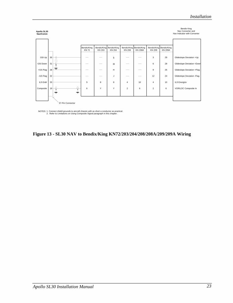
Bendix KingNav Converter and
Nav Indicator with Converter
+GS Flag
-GS Flag
GSI Down
GSI Up
Glideslope Deviation +Flag
30
31
28
32
ILS Enbl
Composite
33
19
ILS Energize
VOR/LOC Composite In6
S
NOTES: 1. Connect shield grounds to aircraft chassis with as short a conductor as practical.2. Refer to Limitations on Using Composite Signal paragraph in this chapter.
Glideslope Deviation -Flag
Glideslope Deviation +Up
Glideslope Deviation +Down
Bendix/KingKN 72
Bendix/KingKN 209
Bendix/KingKN 208A
Bendix/KingKN 208
Bendix/KingKN 204
Bendix/KingKN 203
Bendix/KingKN 209A
J
H
m
Y
8
k
Y
8
2
4
6
10
12
9
6
2
4
3
24
25
28
6
10
29
Apollo SL30Nav/Comm
37-Pin Connector
Figure 13 - SL30 NAV to Bendix/King KN72/203/204/208/208A/209/209A Wiring

Installation
24 Apollo SL30 Installation Manual
Bendix KingIndicator with OBS Resolver
without Converter
+GS Flag
-GS Flag
GSI Down
GSI Up
Glideslope Deviation +Flag
30
31
28
32
13
14
Course Deviation + Right
NOTES: 1. Connect shield grounds to aircraft chassis with as short a conductor as practical.
Glideslope Deviation -Flag
Glideslope Deviation +Up
Glideslope Deviation +Down
Bendix/KingKI 525A
Bendix/KingKI 206
Bendix/KingKI 202
Bendix/KingKPI 552
n
j
n
j
W
V
b
GG
FF
HH
i
h
JJ
Apollo SL30Nav/Comm
P2021 P2061 P1 P2 P101
J
B
E
Course Deviation + Left
NAV Flag +
NAV Flag -
+ From
+ To
OBS Resolver H
OBS Resolver C
OBS Resolver D
OBS Resolver E
OBS Resolver F
OBS Resolver G
F
N
e
S
Z
c
P
L
W
T
H
m
k
J
F
N
e
S
Z
c
P
L
W
T
F
K
Z
T
a
X
Y
V
e
b
g
f
j
k
V
W
a
Z
X
Y
NAV Flag +
NAV Flag -
+ From
+ To
RslvrC
RslvrD
RslvrE
CDI Left
CDI Right
RslvrF
RslvrG
RslvrH
29
10
25
24
26
7
34
16
12
11
15Back Course Lamp VoltageFrom Dimmer
CircuitAmber
BCLight
37-Pin Connector
Figure 14 - SL30 NAV to Bendix/King KI202/206/525A/KPI552 Wiring

Installation
Apollo SL30 Installation Manual 25
RslvrCRslvrD
RslvrE
24
7
26
25
28
32
3416
VREF
COS
SIN
OBS In
Sandel SN3308
+NAV Flag
-NAV Flag
+TO Flag+FR Flag
CDI Left
CDI Right
+NAV Flag
-NAV Flag
+TO Flag+FR Flag
CDI Left
CDI Right
10
29
1211
14
13 19
37
3517
36
18
Back CrseILS Enbl
1533
NOTES: 1. Use shieled cable for resolver signals2. Connect cable shields to the mounting frame: pigtails < 1.25 inches
3. Connect shields chassis ground at both ends of each shielded cable4. Reference Sandel installation manual for switching NAV signals with GPS
RslvrFRslvrG
RslvrH
1634
+GS Flag +GS Flag-GS Flag
283315
32-GS Flag
SL30
3031
14
GSI Up
GSI DownGSI Up
GSI Down
13
37-Pin Connector
Lamp VoltageFrom Dimmer
Circuit.Note 5
AmberBC
Light
5. BC annunciator may be implemented in future software revisions of the SN3308. Refer to Sandel installation manual.
Figure 15 - SL30 NAV to Sandel Discrete Connections

Installation
26 Apollo SL30 Installation Manual
Sandel SN3308
ILS Enbl 33
NOTES: 1. Use shieled cable for resolver signals2. Connect cable shields to the mounting frame: pigtails < 1.25 inches3. Connect shields chassis ground at both ends of each shielded cable
+GS Flag +GS Flag-GS Flag
283315
32-GS Flag
SL30
3031 34
GSI Up
GSI DownGSI Up
GSI Down16
Composite
Gnd
19
37
Composite
ILS Enrgze
1029
827NAV 1 NAV 2
4. Refer to Limitations on Using a Composite Signal paragraph in this chapter
37-Pin Connector
Figure 16 - SL30 NAV to Sandel SN3308 Converter Connections

Installation
Apollo SL30 Installation Manual 27
Navigation Indicator
+GS Flag
-GS Flag
GSI Down
GSI Up
Glideslope +Flag
30
31
28
32
13
14
+ Right
NOTES: 1. Connect shield grounds to aircraft chassis with as short a conductor as practical.
Glideslope -Flag
+Up
+Down
SperryRD 550A
Collins331A-9G
Collins331A-6P
SperryRD 650
29
28 3
8W
36
E
U
6
4
3
5
Apollo SL30Nav/Comm
P1 P2P1
36
D
C
+ Left
NAV Flag +
NAV Flag -
+ From
+ To
OBS A/H
OBS C
OBS D (COS Hi)
OBS E (COS Lo)
OBS F (SIN Lo)
OBS G (SIN Lo)
32
31
27
26
5
4
3
1
7
6
7
6
5
38
37
4
2
1
5
4
3
1
7
6
38
F
B
A
AA
z
FF
DD
CC
BB
S
P
2
1
10
9
8
6
12
11
NAV Flag +
NAV Flag -
+ From
+ To
RslvrC
RslvrD
RslvrE
CDI Left
CDI Right
RslvrF
RslvrG
RslvrH
29
10
25
24
26
7
34
16
12
11
15Back Course Lamp VoltageFrom Dimmer
CircuitAmber
BCLight
37-Pin Connector
P1 P2 P1 P2
NAV Superflag
NAV Superflag Lo
Glideslope Superflag
Glideslope Superflag Lo
33
34
35
39
GS Superflag
NAV Superflag 27
9
Figure 17 - SL30 to Collins 331A-6P, 331A-9G and Sperry RD 550A, RD650 Wiring

Installation
28 Apollo SL30 Installation Manual
LIMITATIONS ON USING A COMPOSITE SIGNALIf an external converter is driven from the composite output in conjunction with a full functionCDI/HSI with resolver, the indicator head type, when selected from the Setup Mode duringthe post installation checkout, should be RESOLVER. In this installation, the composite outputwill be disabled whenever the VOR monitor mode is active or back course localizer mode isenabled. This will cause the external converter to flag. If the CONVERTER option is selectedfrom the Setup Mode as the indicator head type, neither of these two options is available to thepilot and the composite output should always be valid. The CONVERTER setup option shouldbe used if an external converter is the only indicator interfaced to the SL30.
POST INSTALLATION CHECKOUTOnce the unit is installed, complete the checkout procedure to verify proper operation. Referto the User’s Guide for operating instructions.
The steps that are not applicable to a particular installation may be skipped. A checkout logsheet is included on page 34 to fill out during the checkout procedure. Make a photocopy ofthe log sheet for ease of use if desired.
MOUNTING / WIRING CHECK
Verify that all cables are properly secured and shields are connected to the rear of themounting frame. Check the movement of the aircraft controls to verify that there is nointerference.
SETUP AND CHECKOUT
The SL30 has a built-in I/O test mode to simplify system setup and checkout. To operate theSL30 in the Setup Mode, hold down the ó and SYS buttons while switching on the power.You must continue to hold the buttons in until a complete power up is done and SELECT CDI isdisplayed. To return to normal operation, switch the power off, and then back on.
In the Setup Mode, turn the large knob to view each function. In general, press the SEL buttonto activate selection, turn the small knob to view each option, and then press ENT to save thedisplayed value. Pressing SEL again will exit the option without saving any changes.
NAV Setup and Checkout
Indicator Head TypeSet up the SL30 for the indicator head type that it is connected to by using the Setup Mode asfollows.1. Rotate the large knob to the SELECT INDICATOR HEAD TYPE display.2. Press SEL. The type will flash.3. Turn the small knob to select desired option: NONE, RESOLVER, CONVERTER, or SERIAL.
Selecting the RESOLVER option requires calibration, which is available by turning the largeknob CW to the next display. The options are defined as follows:

Installation
Apollo SL30 Installation Manual 29
• NONE: No external resolver is supported. OBS mode allows the user to edit the OBSwith concentric knobs.
• RESOLVER: Auto-decodes resolver setting via six-wire resolver interface. Uses internalDSP to compute course information.
• CONVERTER: Disables all internal OBS functions. Disables VOR monitor and BCselection. It allows use of conventional external converter via the composite outputpin.
• SERIAL: Displays OBS and broadcasts NAV and GS data at 10 Hz rate for use withserial CDI conforming to UPS Aviation Technologies SL30 serial data specificationonly. See Appendix E – Serial Interface Specifications.Note: No serial test messages are sent in the Setup Mode while testing CDI and GSIflags.
4. Press ENT to accept and save the selected option.
Calibrating the Resolver Indicator Head TypeAfter selecting RESOLVER as the indicator head, it is necessary to calibrate the interfacebetween the SL30 and the resolver.1. After selecting RESOLVER as the indicator head type, turn the large knob to the PRESS
SEL TO CALIBRATE RESOLVER display.2. Press SEL.3. Follow the directions on the SL30 display.Note: The accuracy of the system is dependent on this calibration. Do not rush this step.4. At the end of the setup, press ENT to store the results.5. Cycle the power switch (enter the normal mode).6. Tune a VOR station (any VOR frequency).7. Press OBS button.8. Verify that the OBS decodes properly from 0 to 360 degrees.
Control TestIn the Setup Mode, turn the large knob to reach the CONTROL TEST page. This function teststhe operation of the front panel controls on the SL30.1. Press each button. The function name for each control will appear on the display after the
button is pressed.2. Turn the small knob. The numeric values on the right side of the display will change.
Display TestIn the Setup Mode, turn the large knob to reach the PRESS SEL TO TEST DISPLAY page.1. Press SEL.2. A series of display tests will be performed to test each LED. Observe the display for any
missing LEDs.3. When the test is completed, the display will return to normal mode.

Installation
30 Apollo SL30 Installation Manual
Flags TestThe Flags test in Setup Mode sends an active signal for each selected flag so you can test theinterface to the connected devices directly from the front panel while you are on the ground.The Flag tests include LOC (Localizer), BC (Back Course), FR (From), TO (TO), NAV(NAV), and GS (Glideslope). When a selection is in large text, an active signal is sent from theSL30.1. In the Setup Mode, turn the large knob to the FLAGS TEST page.2. Press SEL. The Localizer (LOC) selection will flash.3. Turn the small knob to change the selection to large text. Check the attached indicator for
the appropriate flag. Turn the small knob one click in either direction to change theselection back to small text.
4. Turn the large knob to the next flag type and turn the small knob to change it to large text.You can only select FR or TO as active, not both at the same time.
5. Ensure the flags are reset to all small text when you are finished testing.
CDI TestThis function tests for CDI function and allows for calibration between the SL30 and theattached CDI.1. In the Setup Mode, turn the large knob to reach the CDI TEST page.2. Press SEL to activate selection. The value will flash.3. Rotate the small knob to change the value. The values "0-6" may be used to center the
CDI needle.4. Turn the small knob left or right to center the needle.5. Press ENT when the needle is centered.6. Turning the small knob left or right past a value of "6" will test the deflection of the CDI
needle.
GSI TestThis function tests for GSI function and allows for calibration between the SL30 and theattached GSI.1. In the Setup Mode, turn the large knob to reach the GSI TEST page.2. Press SEL to activate selection. The value will flash.3. Rotate the small knob to change the value. The values "0-6" may be used to center the
GSI needle.4. Turn the small knob left or right to center the needle.5. Press ENT when the needle is centered.6. Turning the small knob left or right past a value of "6" will test the deflection of the GSI
needle.

Installation
Apollo SL30 Installation Manual 31
VHF NAV Checkout
On the GroundCheck the VOR reception with ground equipment, operating VOT or VOR, and verify audioand Morse code ID functions (if possible). Tune a Localizer frequency and verify the CDIneedle and NAV flag, and GSI needle GS flag.
Comm Setup and Checkout
Com RF SquelchThis valued is used by the Comm function to control its squelch level. It is usually notnecessary to adjust this value from its factory setting.1. In the Setup Mode, turn the large knob to reach the COM RF SQUELCH page.2. Press SEL to activate selection. The value will flash.3. Rotate the small knob to change the level number. The range of the number is 25 to 100.
Note: The larger the number the stronger the signal must be in order for the radio tobreak squelch. The factory default value is 56.
4. Press ENT to save the value and exit the Setup Mode.
Microphone 1 and 2 GainSet the microphone gain for microphones 1 and 2 for values from 0 to 255.1. In the Setup Mode, rotate the large knob to select MICROPHONE 1 (or 2) GAIN.2. Press SEL to activate selection. The Mic 1 value will flash.3. Turn the small knob to change the value.4. Turn the large knob to the Mic 2 value. Turn the small knob to change the value.5. Press ENT to accept and save the settings.
Note: A value of 128 will work well for most headset units.
Enable weather frequenciesThis function determines whether the weather frequencies in common use in North Americaare displayed, or not.1. In the Setup Mode, rotate the large knob to select ENABLE WEATHER FREQUENCIES.2. Press SEL to activate selection. The Yes or No value will flash.3. Turn the small knob to change the value.4. Press ENT to accept and save the settings.
VHF Comm Checkout
Receiver / Transmitter OperationTune the unit to a local frequency and verify the receiver output produces a clear andunderstandable audio output. Verify the transmitter functions properly by contacting anotherstation and getting a report of reliable communications. Check the remote flip/flop.

Installation
32 Apollo SL30 Installation Manual
Antenna CheckThe antenna Vswr can be checked using an inline wattmeter in the antenna coax usingfrequencies near both ends of the band. The Vswr should be < 2:1, and is not to exceed 3:1. AVswr of 2:1 will cause a drop in output power of approximately 12%, and 3:1 causesapproximately a 26% drop.
Sidetone Level AdjustmentThe sidetone volume was preset at the factory to a typical audio level. The level can beadjusted using one of the built-in system functions. To adjust the sidetone level:
1. Press SYS, rotate the large knob to the COM RADIO INFO: page, and press ENT.2. Rotate the large knob to the SIDETONE LEVEL: page.3. Rotate the small knob to adjust the sidetone level. The sidetone level is displayed in a
range of 1 to 100, and variable. The sidetone level can be adjusted during transmit.
Transmit Mic SelectionThe Transmit Microphone page controls which microphone is permitted to transmit. ChooseMic 1, 2, or both. To select the Transmit Mic control:1. Press the SYS button and rotate the large knob to TRANSMIT MIC page.2. Rotate the small knob to select MIC1, MIC2, or MIC1+MIC2.3. Select an appropriate frequency, key the transmitter, and talk into the microphones to
check for the intended operation.
FINAL SYSTEM CHECK
The SL30 functions should be complete at this time. The final check includes verifying VORand ILS operation. Start with the unit turned on and operating in the normal mode. Refer tothe user’s manual for operating instructions.
RS-232 Serial Interface ChecksThe interfaces to other equipment, such as the GX series GPS, should be checked as follows:1. Operate the SL30 and GX unit in normal mode.2. Press the Direct To button on the GPS unit and select an airport. Press ENT.3. Operate the SL30 in Comm mode. Press SEL.4. Verify that the remote frequencies of the airport selected via the GPS unit are displayed on
the SL30.
The interface to a DME receiver should be checked as follows:1. Operate the SL30 in NAV mode and ensure the DME is operating with a valid signal.2. Press the SEL button to bring up the NAV frequency recall lists.3. Turn the large knob one click to the left (counterclockwise) to show the DME display
prompt.4. Press ENT to replace the current NAV display with DME data. Verify that DME data is
passed to the SL30.
To check the serial data output connections, verify the data from the SL30 can be displayed onthe other units, such as the MX series multi-function display. For serial interface checks to aserial CDI consult the CDI installation checkout procedures.

Installation
Apollo SL30 Installation Manual 33
Comm Flight Test CheckA flight test is recommended as a final installation verification. The performance may beverified by contacting a ground station at a range of at least 50nm while maintaining anappropriate altitude and over all normal flight attitudes. Performance should be checked usinglow, high, and mid band frequencies.
Check the VOR1. Tune a local VOR station within 50 miles.2. Verify the audio ident/voice quality.3. Verify the Morse code decoder IDs the station (95% probability).4. Fly to and from the station.5. Verify NAV flag, TO/FR flag, and CDI are operational.6. Record accuracy in System Log (see manual).
Check the ILS1. Tune an ILS at the local airport.2. Verify the audio ident/voice quality.3. Verify the Morse code decoder IDs the station (95% probability).4. Fly the approach.5. Verify NAV flag, GS flag, and CDI and GSI are operational.6. Verify BC annunciator.

Installation
34 Apollo SL30 Installation Manual
APOLLO SL30 POST-INSTALLATION CHECKOUT LOG Date: ___/___/___By: _____________
CONFIGURATION INFORMATION: SL30 NAV/COMM 430-6040-3_____ Mod ____ Serial # ___________
TEST MODE CHECKOUT AND SETUP:Avionics Outputs: [ ] Resolver [ ] Converter [ ] Serial [ ] None [ ] Calibration (if Resolver) [ ] Control Test [ ] Display Test [ ] NAV Valid flag [ ] GS Valid flag [ ] TO/FROM flag (OFF, TO, FROM) [ ] External annunciator (BC) [ ] CDI (left, mid, right) [ ] GS (up, mid, down) [ ] Enable Weather Freq Yes ___ No___VHF NAV CHECKOUT:VOR reception with ground equipment [ ] Audio and Morse code ID functions [ ] Verify CDI NAV and GSI GS flagsVHF COMM CHECKOUT: [ ] Receiver / Transmitter operation [ ] Sidetone level set / checked [ ] Antenna check [ ] Transmit Mic selection [ ] Remote flip/flop inputFINAL SYSTEM CHECK: [ ] RS-232 inputs/outputs checked (Optional) [ ] Comm Operation [ ] VOR Check
[ ] Station ID [ ] TO/FR [ ] ILS Check [ ] Left/Right (CDI) [ ] Station ID [ ] Valid Flag (NAV) [ ] Valid Flags (NAV/GS) [ ] Radial (To/From) [ ] Left/Right (CDI)
______ Bearing Error [ ] Up/Down (GSI) [ ] Remote Flip/Flop input [ ] BC Function (Annunciator)COMMENTS:

Installation
Apollo SL30 Installation Manual 35
INSTRUCTIONS FOR CONTINUED AIRWORTHINESSModification of an aircraft for the installation of the SL30 obligates the aircraft operator toinclude the maintenance information provided by this section in the operator’s AircraftMaintenance Manual and the operator’s Aircraft Scheduled Maintenance Program.1. Maintenance manual information (system description, operation, location, removal,
testing, etc.) is contained within this document and any information should be copied to,and/or included with, the operator’s airplane Maintenance Manual.
2. Line Replaceable Unit (LRU) part numbers and other necessary part numbers contained inthe installation data package should be placed into the aircraft operator’s airplaneIllustrated Parts Catalog (IPC).
3. The specific wiring diagram information, along with the supplemental informationdescribed in the Installation Manual, pertaining to the installation of this unit, should beplaced into the aircraft operator’s airplane Wiring Diagram Manuals.
4. Scheduled Maintenance Program tasks to be added to the operator’s maintenanceprogram are found in Appendix B – Periodic Maintenance, of this installation manual.

Installation
36 Apollo SL30 Installation Manual
NOTES

Specifications
Apollo SL30 Installation Manual 37
SECTION 3 - SPECIFICATIONSThis section includes detailed electrical, physical, environmental and performance specificationsfor the Apollo SL30.
ELECTRICALInput voltage............................................10 VDC to 40 VDC, reverse polarity protected
Input current (VHF navigation input) .......325 mA typical, 500 mA max at 13.75 VDC170 mA typical, 350 mA max at 27.5 VDC
Input current (Comm input) .....................270 mA typical, 2 A max at 13.75 VDC, receive130 mA typical, 900 mA max at 27.5 VDC, receive2.1 A typical, 3.2 A max at 13.75 VDC, transmit1.0 A typical, 1.4 A max at 27.5 VDC, transmitNote: receive max at full receive audio, transmitmax at 90% modulation at 1000 Hz.
Input power (Comm input) ......................3.7 watts typical, receive28 watts typical, transmit
Internal fuses ...........................................Nav input: 3 amp fast blow, socketed on boardComm input : 7 amp fast blow, soldered in board
Memory backup.......................................Internal flash memory
PHYSICALHeight......................................................1.30 inches (3.30 cm)
Width.......................................................6.25 inches (15.88 cm)
Depth.......................................................11.452 inches (29.09 cm) behind panel, includingmounting frame and connectors
Weight (without mounting frame) ............2.25 lb. (1.02 kg)
ENVIRONMENTALThe Apollo SL30 is designed and tested to meet appropriate categories of RTCA/DO-160Cand RTCA/DO-160D. The Environmental Qualification Form is included in Appendix C.
Operating temperature .............................-20°C to +55°C
Storage temperature.................................-55°C to +85°C
Temperature variation..............................2°C per minute
Humidity..................................................95% at 65°C for 48 hours
Maximum altitude ....................................25,000 feet
Cooling....................................................Not required

Specifications
38 Apollo SL30 Installation Manual
Figure 18 - Unit Dimensions
AVIONICS OUTPUTSCDI L/R deviation....................................±150 mV full scale, will drive up to 200-ohm load
TO/OFF/FROM flag ................................±250 mV, TO/FROM indication, will drive up to200-ohm load
Nav valid flag...........................................+300 mV for valid indication, will drive up to 200-ohm load
Nav superflag...........................................Vin - 2 volts minimum for valid, source capability of400 mA
GSI U/D deviation ...................................±150 mV full scale, will drive up to 200-ohm load
GS valid flag ............................................+300 mV for valid indication, will drive up to 200-ohm load
GS superflag ............................................Vin - 2 volts minimum for valid, source capability of400 mA
Annunciators............................................Open collector outputs capable of sinking up to400 mA for turning on annunciator lamps• BC• Localizer
Power Control .........................................Open collector output capable of sinking up to50 mA. Active when unit is powered up.

Specifications
Apollo SL30 Installation Manual 39
NAV RECEIVER PERFORMANCE
VORTSO compliance ......................................TSO-C40c (DO-196)
Applicable documents ..............................RTCA DO-196
Operational class......................................N/A
Accuracy category ...................................B -46oC to + 55o C
Frequency range.......................................108.00 to 117.95 MHz in 50 kHz increments
Frequency tolerance .................................0.0008%
Cross modulation products.......................At least 60 dB down
Receiver sensitivity ..................................108 MHz –115 dBm typical117 MHz –117 dBm typical
Course accuracy.......................................RTCA DO-196 two sigma limit: 3o
SL30 performance: less than 0.5o typical
Audio output ...........................................With a 1 kHz tone 30% modulation at least 100 mWoutput into 500 ohm loads
Ident/voice...............................................With 100 mV input, 30% modulation at 1020 Hz,the ident/voice tone ratio shall not be less than15 dB
Audio response ........................................Less than 6 dB variation from 350 Hz to 2500 Hz
LOCALIZER
TSO compliance ......................................TSO-C36e (DO-195)
Applicable documents ..............................RTCA DO-195
Operational class......................................A manual landing systems
Accuracy category ...................................B -46oC to + 55oC
Frequency range.......................................108.00 to 111.95 MHz
Frequency tolerance .................................0.0008%
Cross modulation products.......................At least 60 dB down
Receiver sensitivity ..................................-110 dBm typical
Centering error ........................................RTCA DO-195 two sigma limit: 6.6% of full scaleSL30 performance: less than 1.0% typical
Audio output ...........................................With a 1 kHz tone 30% modulation at least 100 mWoutput into 500 ohm loads
Ident/voice...............................................With 100 mV input, 30% modulation at 1020 Hz,the ident/voice tone ratio shall not be less than15 dB
Audio response ........................................Less than 6 dB variation from 350 Hz to 2500 Hz

Specifications
40 Apollo SL30 Installation Manual
GLIDESLOPE
TSO compliance.......................................TSO-C34e (DO-192)
Applicable documents ..............................RTCA DO-192
Operational class ......................................N/A
Accuracy category ...................................B -46oC to + 55oC
Frequency range.......................................329.150 to 335.00 MHz
Frequency tolerance .................................0.0008%
Cross modulation products.......................At least 60 dB down
Receiver sensitivity...................................-95 dBm typical
Centering error.........................................RTCA DO-195 two sigma limit: 6.7% of full scaleSL30 performance: less than 2.0% typical
OBS RESOLVER
TSO compliance.......................................TSO-C40c (DO-196)
Applicable documents ..............................RTCA DO-196
Operational class ......................................N/A
Accuracy category ...................................B -46oC to + 55oC
Output signal frequency............................300 Hz ± 2 Hz
Output voltage (automaticallyadjusted during calibration) ...............5 Vpp to 10 Vpp
Input voltage max (calibrated)..................5 Vpp average
Resolver return loss range ........................50 – 100%
Output loading at max voltage..................100 ohms impedance
Resolution................................................0.25o rounded to 1o steps
COMPOSITE OUTPUT
VOR ModeBand pass frequency.................................0 Hz to 15 kHz
Variation over frequency range.................Less than 2 dB
Output signal voltage ...............................0.630 VRMS (0.410 VRMS @ 30 Hz, 0.480 VRMS @9,960 Hz)
Output loading .........................................1,000 ohms (max)
LOC ModeBand pass frequency.................................0 Hz to 15 kHz
Variation over frequency range.................Less than 2 dB

Specifications
Apollo SL30 Installation Manual 41
Output signal voltage ...............................0.390 VRMS (0.275 VRMS @ 90 Hz, 0.275 VRMS @150 Hz)
Output loading.........................................1,000 ohms (max)
ILS energize signal...................................Sinks up to 400 mA (max)
COMM RECEIVER PERFORMANCEClass........................................................D
Frequency range.......................................118.000 to 136.975 MHz, 760 channels
Sensitivity................................................1 µV (2 µV hard) for 6 dB S+N/N with 30%modulation at 1000 Hz
Selectivity................................................< 6dB variation at ± 7 kHz, > 60 dB at ± 22 kHz
Speaker audio output level.......................12 watts into 4 Ω, 8 watts into 8 Ω
Headphone audio output level..................280 mW into 100 Ω, 120 mW into 500 Ω
Distortion ................................................< 5% at rated output at 1000 Hz
AGC characteristics .................................< 3db variation in audio output from 5 µV to 100mV input, 15% to 90% modulation
Squelch control........................................Automatic squelch with manual override
COMM TRANSMITTER PERFORMANCEClass........................................................4
Output power ..........................................8 watts minimum carrier at >12 VDC input,6 watts minimum at 10 VDC input(transmit is locked out below 9 volts input)
Frequency range.......................................118.000 to 136.975 MHz, 760 channels
Frequency tolerance .................................±15 ppm from -20°C to +70°C
Microphone input.....................................Two inputs, standard carbon or dynamic mic withintegrated preamp providing minimum 70 mv rmsinto 1000 Ω load
Modulation capability...............................85% with 100 mv to 1000 mv rms microphone inputat 1000 Hz
Audio frequency distortion.......................< 10% at 85% modulation at 350 to 2500 Hz
Audio frequency response ........................< 4 dB variation with 350 to 2500 Hz, 85%modulation
Carrier noise level ....................................> 35 dB down
Sidetone output .......................................up to 280 mW into 100 Ω, 120 mW into 500 Ω

Specifications
42 Apollo SL30 Installation Manual
Duty cycle................................................100%
Stuck mic time-out ...................................35-second time-out, reverts to receive
INTERCOM PERFORMANCEMicrophone input.....................................Two inputs, standard carbon or dynamic mic with
integrated preamp providing minimum 70 mv rmsinto 1000 Ω load
Headphone audio output level ..................280 mW into 100 Ω, 120 mW into 500 Ω
AGC characteristics .................................output varies < 3 dB with input of 100 mv rms to1000 mv rms
CONTROL INPUTSTransmit key ............................................Input pulled low to ground to enable the transmitter
Intercom select.........................................Input pulled low to ground to enable the intercomfunction
Flip/Flop ..................................................Remote Comm flip/flop input, connect to amomentary button to ground for remote flip/flopoperation.
ANTENNA REQUIREMENTS
COMM ANTENNA
The Apollo SL30 requires a VHF Comm antenna meeting the following specifications:
• Standard 50 Ω vertically polarized antenna with a VSWR < 2.5:1.
NAV ANTENNA
The Apollo SL30 requires a VHF NAV antenna meeting the following specifications:
• Standard 50 Ω horizontally polarized antenna with a VSWR <3:1• Capable of receiving VOR/LOC/GS (Recommend Comant Industries P/N CI 157P)• 108.00 – 117.95 MHz (VOR/LOC)• 328.60 – 335.4 MHz (GS)
Note: Multiple NAV antennas may be used with an RF signal splitter/combiner, part number115-0007, at the radio. Refer to page 14.

Specifications
Apollo SL30 Installation Manual 43
SERIAL INTERFACERS-232 ....................................................Defined in Appendix E - Serial Interface
Specifications
REAR CONNECTOR PINOUTThe SL30 includes two rear panel connectors, a 15-pin for the Comm interface connectionsand a 37-pin for the rear panel connections. The pinout for the connectors is listed in thefollowing tables.
Table 2 - Comm Interface Connector Pinout
Pin # I/O Connection Function1 I Power + Main DC power input2 I Reserved Do not connect3 O Reserved Do not connect4 I TxKey Transmit enable key, pulled low to transmit5 -- NC Do not connect6 O Speaker Speaker terminal output7 I Mic ground Microphone input ground connection8 I Mic 1 Microphone input #19 I Power ground Main power ground input10 I Reserved Do not connect11 O Reserved Do not connect12 I Intercom select Intercom function select, pulled low to turn on the intercom
function13 O Audio ground Speaker and headphone ground connection14 O Headphone Headphone terminal output15 I Mic 2 Microphone input #2
1 8
9 15
Viewed from rear of unit

Specifications
44 Apollo SL30 Installation Manual
Table 3 - Rear Panel Connector Pinout
Pin # I/O Connection Function1 I Power + Main DC power input2 I Power ground Main power ground input3 O Serial ground RS-232 signal ground4 I RxD1 RS-232 channel 1 serial data input5 O TxD1 RS-232 channel 1 serial data output6 I Test Input Reserved for manufacturers test7 I OBS_D S1 Resolver input pin from Channel D (COS)8 I Flip/Flop Remote NAV/Comm frequency flip/flop input9 O GSI superflag GSI high level valid flag output10 O Nav + valid Nav low level valid flag output11 O + FROM + From flag output12 O + TO + To flag output13 O CDI + Right CDI + Right output14 O CDI + Left CDI + Left output15 O Back course Active low output when reverse sensing is engaged16 O OBS_F S4 Resolver input pin from Channel F (SIN)17 -- Reserved Do not connect18 -- Reserved Do not connect19 O Composite Output VOR/LOC composite signal20 O Audio ground Audio signal ground pin21 O Reserved Do not connect22 O Reserved Do not connect23 O NAV Audio Output Low level audio output24 O OBS_H R HI Resolver output pin to channel H25 O OBS_C R LO Resolver return signals C26 I OBS_E S3 Resolver return signals E27 O Nav superflag Nav high level superflag output28 O GSI + valid GSI low level valid flag output29 O NAV - valid Signal ground for NAV valid flag30 O GSI + Up GSI +Up output31 O GSI + Down GSI +Down output32 O GSI - Valid Signal ground for GS valid flag33 O ILS energize Active low output when a localizer frequency is tuned34 O OBS_G S2 Resolver return signals G35 -- Reserved Do not connect36 O Power control Power control output sinks up to 50 mA when unit is on37 O Ground (comp) VOR/LOC composite ground return
1 19
20 37
Viewed from rear of unit

Limitations
Apollo SL30 Installation Manual 45
SECTION 4 - LIMITATIONS
INSTALLATIONFor minimum equipment and connections required for VFR or IFR installations, refer to theMinimum System Configuration section on page 9.
Installations of the SL30 Nav/Comm functions are to be made in accordance with AC 20-67B,TSO-C37d, TSO-C38d, TSO-C128, TSO-C34e, TSO-C36e, TSO-C40c, TSO-C66c, FARPart 21-Subpart O, FAR Part 21-Subpart K, or other appropriate FAA approved guidelines.
OPERATIONAL
An aircraft radio station license may be required with the SL30 for transmitting.
Note: It is recommended that aircraft be equipped with at least two NAV receivers and twoComm transceivers for IFR use. If this practice is followed, the loss of NAV function, Commfunction or both will not result in the loss of either of the NAV or Comm functions at theaircraft level. This will support a System Safety Assessment of minor for IFR operations.Refer to AC 23.1309-1C.

Limitations
46 Apollo SL30 Installation Manual
NOTES

Troubleshooting
Apollo SL30 Installation Manual 47
APPENDIX A - TROUBLESHOOTINGThis appendix provides information to assist troubleshooting if problems occur aftercompleting the installation. Use Table 4 to assist in troubleshooting.
Table 4 - Troubleshooting Guide
Problem Cause SolutionThe SL30 does not power on. The unit is not getting power. Check power connections, breakers,
and main avionics switch.No NAV audio Output disabled or set to a low level. Check System page; NAV Options;
NAV Audio Level.NAV audio in Comm Mixed with Comm feature. Check System page; NAV Options;
Mix NAV Audio With Com.The SL30 does not transmit. The TxKey input is not being pulled
low.Check the TxKey (mic key) input,pulled low for transmit.
A weather channel is selected. Select a different frequency, the unitwill not transmit on a weatherchannel.
No power to the Comm. Make sure power input is connectedto the Comm 15 pin connector.
The input voltage is too low. Increase input supply voltage to > 9volts DC.
The sidetone level is too low ortoo high.
Wrong type of headsets, or levelneeds adjustment.
See theSidetone Level Adjustment on page32.
The intercom doesn’t function. Control input not connected. The intercom select input must bepulled to ground to turn on theintercom function.
Active frequency signal present. Change the active frequency. Theactive frequency has priority.
No voice activation, or have to talktoo loud.
Change the intercom level thresholdusing the setup function described inthe user’s manual.
CONTACTING THE FACTORY FOR ASSISTANCEIf the Apollo SL30 unit fails to operate despite troubleshooting efforts, contact the UPSAviation Technologies factory for assistance.
UPS Aviation Technologies Inc.2345 Turner Rd. SESalem, Oregon 97302USA
Phone (503) 581-8101 or 1-800-525-6726
Be prepared with the following information about the installation:• Installation configuration (accessories, antenna, ...)• Model number, part number with mod levels, and serial number

Troubleshooting
48 Apollo SL30 Installation Manual
• Software versions• Description of problem• Efforts made to isolate the problem• other installed avionics

Periodic Maintenance
Apollo SL30 Installation Manual 49
APPENDIX B - PERIODIC MAINTENANCEThe SL30 unit is designed to not require any regular general maintenance except as included inthis section.
VOR CHECKSEven though the SL30 is designed to utilize the most state-of-the-art DSP technology andmaintain a very high accuracy and repeatability record, it still must undergo the VOR accuracychecks required for IFR flight. Refer to CFR 14 paragraph 91.171. Every 30 days verify thelimits of the permissible indicated bearing error.
The last VOR check information may be entered into the SL30 via the system mode VORCHECK. See the operator’s manual for details.
EQUIPMENT CALIBRATIONThe SL30 design requires very few adjustments or calibration to be made. In fact, there are nointernal manual adjustments.
REFERENCE OSCILLATOR (COMM ONLY)The reference oscillator frequency should be checked approximately every 3 to 5 years toensure the units transmit frequency is within allowable tolerance.
The oscillator frequency can be checked by connecting the transmitter output through anappropriate load to a calibrated frequency counter. The transmit frequency should be within15ppm of the selected channel frequency. Contact the UPS Aviation Technologies factory forinstructions on adjusting the frequency if required.
CLEANING THE FRONT PANELThe front bezel, keypad, and display can be cleaned with a soft cotton cloth dampened withclean water. DO NOT use any chemical cleaning agents. Care should be taken to avoidscratching the surface of the display.

Periodic Maintenance
50 Apollo SL30 Installation Manual
NOTES

Environmental Qualifications
Apollo SL30 Installation Manual 51
APPENDIX C - ENVIRONMENTAL QUALIFICATIONSThe Apollo SL30 has been tested to the following environmental categories per proceduresdefined in RTCA/DO-160C.
Environmental Qualification FormModel:Part No:TSO No:
SL30 Comm portion430-6040-3XXTSO-C37d, TSO-C38d, & TSO-C128
Manufacturer: UPS Aviation Technologies Inc. 2345 Turner Road SE Salem, Oregon 97302
Conditions Section Description of Conducted TestsTemperature and Altitude 4.0 Equipment tested to Category C1 In-flight Loss of Cooling 4.5.4 No cooling required Altitude 4.6.3 Equipment tested to 35,000 feetTemperature Variation 5.0 Equipment tested to Category C, 2°C/minHumidity 6.0 Equipment tested to Category A, standard humidity
environmentOperational Shocks and CrashSafety
7 Equipment tested for both operational and crash safetyshocks. (Equipment operated normally after the crash safetyshocks.)
Vibration 8.0 Equipment tested without shock mounts to Categories B, M,and N
Explosion Proofness 9.0 Equipment identified as Category X, no test requiredWaterproofness 10.0 Equipment identified as Category X, no test requiredFluids Susceptibility 11.0 Equipment identified as Category X, no test requiredSand and Dust 12.0 Equipment identified as Category X, no test requiredFungus Resistance 13.0 Equipment identified as Category X, no test requiredSalt Spray 14.0 Equipment identified as Category X, no test requiredMagnetic Effect 15.0 Equipment is Class ZPower Input 16.0 Equipment tested to Categories A & BVoltage Spike 17.0 Equipment tested to Category AAudio Frequency ConductedSusceptibility - Power Inputs
18.0 Equipment tested to Categories A & B
Induced Signal Susceptibility 19.0 Equipment tested to Category ZRadio Frequency Susceptibility(Radiated and Conducted)
20 Equipment tested to Category V for conducted, Category Ufor radiated
Emission of Radio FrequencyEnergy
21 Equipment tested to Category Z
Lightning Induced TransientSusceptibility
22.0 Equipment tested to Categories A3 and B2
Lightning Direct Effects 23.0 Equipment identified as Category X, no test requiredIcing 24.0 Equipment identified as Category X, no test requiredRemarks:

Environmental Qualifications
52 Apollo SL30 Installation Manual
The Apollo SL30 has been tested to the following environmental categories per proceduresdefined in RTCA/DO-160D.
Environmental Qualification FormModel:Part No:TSO No:
SL30 NAV portion430-6040-3XXTSO-C34e, TSO-C36e, TSO-C40c, &TSO-C66c
Manufacturer: UPS Aviation Technologies Inc. 2345 Turner Road SE Salem, Oregon 97302
Conditions Section Description of Conducted TestsTemperature and Altitude 4.0 Equipment tested to Category B1 with
Operating temp: -20ºC to +55ºCShort time hi temp: to +70ºCGround survival temp: -55ºC to +85ºC
In-flight Loss of Cooling 4.5.4 No cooling required Altitude 4.6.1 Equipment tested to 25,000 feetTemperature Variation 5.0 Equipment tested to Category C, 2°C/minHumidity 6.0 Equipment tested to Category A, standard humidity
environmentOperational Shocks and CrashSafety
7 Equipment tested for both operational and crash safetyshocks to Category B. (Equipment operated normally afterthe crash safety shocks.)
Vibration 8.0 Equipment tested without shock mounts to Categories R-G,S-M
Explosion Proofness 9.0 Equipment identified as Category X, no test requiredWaterproofness 10.0 Equipment identified as Category X, no test requiredFluids Susceptibility 11.0 Equipment identified as Category X, no test requiredSand and Dust 12.0 Equipment identified as Category X, no test requiredFungus Resistance 13.0 Equipment identified as Category X, no test requiredSalt Spray 14.0 Equipment identified as Category X, no test requiredMagnetic Effect 15.0 Equipment is Class Z, <0.3 metersPower Input 16.0 Equipment tested to Categories A & BVoltage Spike 17.0 Equipment tested to Category AAudio Frequency ConductedSusceptibility - Power Inputs
18.0 Equipment tested to Categories A & B
Induced Signal Susceptibility 19.0 Equipment tested to Category ZRadio Frequency Susceptibility(Radiated and Conducted)
20 Equipment tested to Category V
Emission of Radio FrequencyEnergy
21 Equipment tested to Category M
Lightning Induced TransientSusceptibility
22.0 Equipment tested to -Categories A3 and B2
Lightning Direct Effects 23.0 Equipment identified as Category X, no test requiredIcing 24.0 Equipment identified as Category X, no test requiredElectrostatic Discharge (ESD) 25.0 Equipment tested to Category ARemarks:

Accessories
Apollo SL30 Installation Manual 53
APPENDIX D - ACCESSORIESThis appendix includes information on accessory items available for the Apollo SL30. Refer tothe information that is provided with those items for complete specifications and installationinstructions.
FROM UPS AVIATION TECHNOLOGIES
Splitter/CombinerUPS Aviation Technologies Part #:.....115-0007
Manufacturer......................................Mini-Circuits
Manufacturer Part #: ..........................ZFSC-2-1B BNC
The splitter/combiner is used when dual antennas and/or dual SL30s are installed in the aircraft.Refer to page 14.Internal FuseUPS Aviation Technologies Part #:.....S172-0007-012
Description.........................................3 amp slow blow fuse

Accessories
54 Apollo SL30 Installation Manual
NOTES

Serial Interface Specifications
Apollo SL30 Installation Manual 55
APPENDIX E - SERIAL INTERFACE SPECIFICATIONSThis appendix includes the interface specifications for the RS-232 serial port. The RS-232 portcan be used to input active and standby frequencies, and is used to input frequencies from aremote source, such as the SL50/60 and 2001 GPS. The interface format conforms to NMEA0183 message format specifications.
INPUT COMMANDSThe following input command messages are supported:
• Input airport identifier associated with remote Comm frequency list• Input Comm frequency data from a remote source• Input VOR frequency data from a remote source• End of VOR frequency list from a remote source• Start of Localizer frequency list from a remote source• Input Localizer frequency data from a remote source• Request data output• Set active VOR/LOC frequency data from a remote source• Set standby VOR/LOC frequency data from a remote source• Set standby COMM frequency data from remote source• Set NAV audio mode• Set Omni-Bearing Select (OBS) value from remote source• DME sensor input
OUTPUT MESSAGESSL30 output messages include:
• Reset status• CDI, GSI, and flags• Decoded OBS setting• Radial from active VOR• Radial from standby VOR• Decoded station identifier• Communications error• Receiver status• NAV audio mode• NAV microcontroller software version• NAV DSP software version• Comm transceiver status• Comm software version

Serial Interface Specifications
56 Apollo SL30 Installation Manual
DATA FORMATThe data format for the serial communication is:
• Baud rate 9600• Data bits 8• Stop bits 1• Parity none
MESSAGE FORMATSAll messages will conform to the NMEA 0183 proprietary message format as follows. Allcharacters will be standard ASCII characters. No binary data characters will be used.
“$” .......................... Start of message character, ASCII “$” (024h).“P” ........................... Proprietary message identifier.“MRR” .................... II Morrow company identifier.c................................ Message class identifier. Used to identify a message as either a
COMM or a VHF NAV message. Those message types which arealso supported by the SL40 VHF Comm Radio Serial Interface willuse the “C” identifier to allow the SL30 to accept COMM radiocommands from existing products. All other messages will use the“V” identifier to indicate that they relate to a VHF NAV receiver.
nn ............................ Message identifier, two-digit number in ASCII characters.d.....d ...................... Message data characters defined for each message.chksum .................... Message checksum, including message identifier through data
characters. The two-digit checksum is generated by adding allvalues of valid characters together, ignoring carry (if any). Thisvalue is converted into two encoded hex1 characters (30h-3Fh).
<CR> ...................... ASCII carriage return (0Dh).<LF> ....................... ASCII line feed (0Ah).
The maximum message length, including the start of message character (“$”) and the end ofmessage <CR><LF> sequence, is 25 bytes.
This message format is the same as is used in the SL40 VHF Comm Radio. The SL30 will be ableto accept all messages intended for an SL40 without generating a serial communications error. Itwill ignore all of those messages, the only exception being those messages used to input Commfrequency lists from a remote source.
1 Encoded hex: each character consists of 4 bits of data placed in the low order nibble +30h. For example, the 8-bitvalue 5Fh would be encoded as two characters with values of 35h and 3Fh, which map to the ASCII characters “5”and “?”, respectively.

Serial Interface Specifications
Apollo SL30 Installation Manual 57
MESSAGE DEFINITIONS
INPUT MESSAGES
Remote COMM Frequency ListsThe following two commands work together in allowing remotely connected devices to provideCOMM frequency lists associated with an airport to the SL30. The host device should first sendthe Remote Airport Identifier Name command (message identifier 04), followed by a sequence ofRemote Frequency Input commands (message identifier 05). The list type field is used to tie thetwo commands together. The SL30 will receive up to 10 Comm frequency lists, each containingup to twenty entries.
Remote Airport Identifier NameThis input command provides the airport identifier name that is used to identify to the user whichairport facility that the list of frequencies is associated with.
Message format:“C” ................ Message Class. This is a COMM message.“04”............... Message Identifier.t ..................... List type: (ASCII) “0”, “1”,…,”9”aaaa ............... Airport Identifier of the frequency list. Note that if the airport identifier is 3
characters, then the 4th character will be filled with a space. AirportIdentifiers are restricted to using ASCII characters 0-9 and A-Z.
Example message:$PMRRC041SLE<SP><chksum><CR><LF>
Airport Identifier to be associated with list #1, Airport Identifier to display is “SLE “.
Remote Airport Frequency InputThis message is used to input COMM frequency data used for the remote recall function.
The data included is a character defining the list type, a character defining the frequency type(tower, ground, ATIS, ...) and 2 characters defining the frequency. The SL30 module will acceptthe first 10 frequencies received through the serial port for each airport.
Message format:“C” ................ Message Class. This is a COMM message.“05”............... Message Identifier.t ..................... List type: (ASCII) “0”, “1”,…, “9”f..................... Frequency type: 0-Fh; use encoded hex2 (30h-3Fh).
0 = Tower Frequency (TWR)1 = Ground (GND)2 = Automatic Terminal Information Service or ATIS (ATS)
2 Encoded hex: each character consists of a 4-bit data placed in the low order nibble +30h. For example, the 8-bitvalue 5Fh would be encoded as two characters with values of 35h and 3Fh, which map to the ASCII characters “5”and “?”, respectively.

Serial Interface Specifications
58 Apollo SL30 Installation Manual
3 = Air Traffic Frequency (ATF)4 = Approach (APP)5 = Arrival (ARR)6 = Automatic Weather Observing Station (AWS)7 = Clearance/Delivery (CLR)8 = Common Traffic Advisory Frequency (CTF)9 = Departure (DEP): = Flight Service Station (FSS); = Remote Flight Service Station (RFS)< = Unicom (UNI)= = Mandatory Frequency (MF)> = No type specified? = undefined
mk .................Frequency: m = MHz, where m = desired MHz frequency – 30h, with thedesired frequency ranging from 118 to 136, or 46h to 48h; k = kHz, wherek = (desired kHz offset / 25 kHz) + 30H, with the desired frequency rangeof 000 to 975 kHz in 25 kHz, or 30h to 57h.
Example message:$PMRRC0511IT<chksum><CR><LF>
Additional frequency list “1”, ground frequency type, 121.900 MHz.
REMOTE VOR LIST
The following two commands work together in allowing remotely connected devices to provide alist of VOR frequencies to the SL30. The remote device will send a sequence of Remote VORInput commands (message identifier 20). When all of the VOR Input commands have been sent,the remote device should send a Remote VOR List Trailer command (message identifier 21) toterminate the list. The transmitted list will not be considered complete by the SL30 until itreceives the trailer message. The unit will maintain a single remote VOR list, so each list receivedwill replace any previous list. There may be up to twenty entries in the remote VOR list. Anyentries past twenty will be ignored.
Remote VOR InputThis input is used to input VOR frequency data used for the remote recall function.
The data consists of five characters for the VOR station identifier followed by two charactersdefining the VOR frequency.

Serial Interface Specifications
Apollo SL30 Installation Manual 59
Message format:“V”................ Message Class. This is a VHF NAV message.“20”............... Message Identifier.vvvv............... VOR station identifier. Note that if the station identifier is less than four
characters, then the trailing characters will be filled with spaces. StationIdentifiers are restricted to using ASCII characters 0-9 and A-Z.
mk ................. Frequency: m = MHz, where m = desired MHz frequency – 30h, with thedesired frequency ranging from 108 to 117, or 3Ch to 45h; k = kHz, wherek = (desired kHz offset / 25 kHz) + 30h, with desired frequency range of000 to 975 kHz in 50 kHz steps, or the even numbers from 30h to 56h.Note that the field will be checked to ensure that it is in range and a validVOR frequency. Frequencies used for localizers, which are in the range of108.10 to 111.95 MHz, will not be accepted in this message type.
Example message:$PMRRV20UBG<Sp>E@<chksm><CR><LF>
VOR station identifier is “UBG ”, VOR frequency is 117.400 MHz.
Remote VOR List TrailerThis input command marks the end of a VOR list sent by a remote device.
Message format:“V”................ Message Class. This is a VHF NAV message.“21”............... Message Identifier
Example message:$PMRRV21<chksm><CR><LF>
Indicates the start of a remote VOR list.
REMOTE LOCALIZER LIST
The following two commands work together in allowing remotely connected devices to provide alist of localizer frequencies associated with an airport to the SL30. The remote device should firstsend the Remote Localizer List Header command (message identifier 22), followed by a sequenceof Remote Localizer Input commands (message identifier 23). The SL30 maintains a singleremote localizer list, so each new list received will replace any previous list. Subsequentreceptions of localizer lists for the same airport are ignored. There may be up to twenty entries inthe remote Localizer list. Any entries past twenty will be ignored.
Remote Localizer List HeaderThis input command marks the beginning of a Localizer list sent by a remote device. It specifiesthe five character airport identifier associated with the localizer frequencies in the list.

Serial Interface Specifications
60 Apollo SL30 Installation Manual
Message format:“V” ................Message Class. This is a VHF NAV message.“22” ...............Message Identifier.aaaa ...............Airport identifier. Note that if the airport identifier is less than four
characters, then the trailing characters will be filled with spaces. AirportIdentifiers are restricted to using ASCII characters 0-9 and A-Z.
Example message:$PMRRV22SLE<Sp><chksum><CR><LF>
Indicates the start of a remote localizer list associated with the airport “SLE ”.
Remote Localizer InputThis input is used to input Localizer frequency data used for the remote recall function.
The data consists of three characters to identify the runway associated with the localizer, followedby two characters defining the frequency.
Message format:“V” ................Message Class. This is a VHF NAV message.“23” ...............Message Identifier.iiii...................Station or Runway identifier. This field will provide an identifier for the
localizer which can be either the actual station identifier or a stringindicating the runway associated with the localizer. The station identifiercan be up to four characters long. A runway identifier will typically be twonumbers that indicate the runway direction followed by the character “R”,“C”, or “L” to differentiate between parallel runways (right, center, andleft). Note that if either type of identifier is less then four characters, thenthe trailing characters will be filled in with spaces. Identifiers are restrictedto using ASCII characters 0-9 and A-Z.
mk .................Frequency: m = MHz, where m = MHz frequency – 30h, with the desiredfrequency ranging from 108 to 111 MHz, or 3Ch to 3Fh; k = (desired kHzoffset / 25 kHz) + 30h, where the desired frequency ranges from 000 to950 kHz, or the even numbers from 30h to 56h. Note that the field will bechecked to ensure that it is in range and a valid localizer frequency.Frequencies used for VORs, which can also be found in the range of108.10 to 111.95 MHz, will not be accepted in this message type.
Example message:$PMRRV2331<Sp><Sp>><<chksm><CR><LF>
Identifier is “31 ”, indicating a runway, and the localizer frequency is 110.300 MHz.
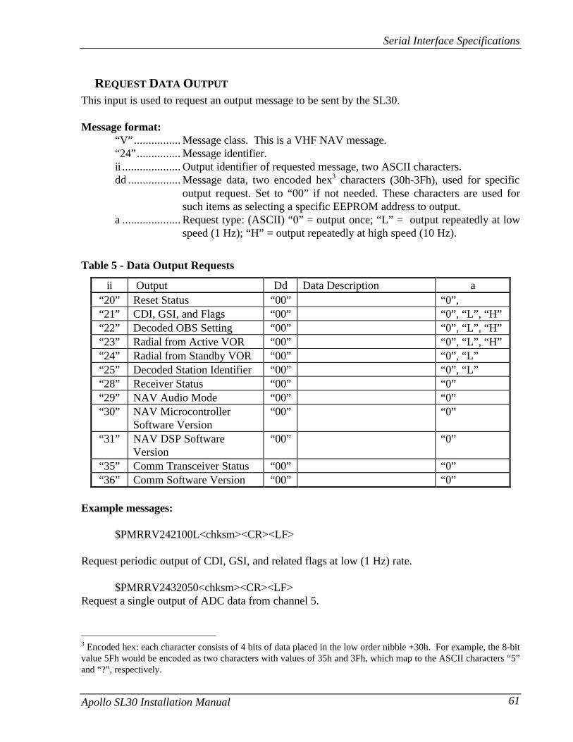
Serial Interface Specifications
Apollo SL30 Installation Manual 61
REQUEST DATA OUTPUT
This input is used to request an output message to be sent by the SL30.
Message format:“V”................ Message class. This is a VHF NAV message.“24”............... Message identifier.ii .................... Output identifier of requested message, two ASCII characters.dd .................. Message data, two encoded hex3 characters (30h-3Fh), used for specific
output request. Set to “00” if not needed. These characters are used forsuch items as selecting a specific EEPROM address to output.
a .................... Request type: (ASCII) “0” = output once; “L” = output repeatedly at lowspeed (1 Hz); “H” = output repeatedly at high speed (10 Hz).
Table 5 - Data Output Requests
ii Output Dd Data Description a“20” Reset Status “00” “0”,“21” CDI, GSI, and Flags “00” “0”, “L”, “H”“22” Decoded OBS Setting “00” “0”, “L”, “H”“23” Radial from Active VOR “00” “0”, “L”, “H”“24” Radial from Standby VOR “00” “0”, “L”“25” Decoded Station Identifier “00” “0”, “L”“28” Receiver Status “00” “0”“29” NAV Audio Mode “00” “0”“30” NAV Microcontroller
Software Version“00” “0”
“31” NAV DSP SoftwareVersion
“00” “0”
“35” Comm Transceiver Status “00” “0”“36” Comm Software Version “00” “0”
Example messages:
$PMRRV242100L<chksm><CR><LF>
Request periodic output of CDI, GSI, and related flags at low (1 Hz) rate.
$PMRRV2432050<chksm><CR><LF>Request a single output of ADC data from channel 5.
3 Encoded hex: each character consists of 4 bits of data placed in the low order nibble +30h. For example, the 8-bitvalue 5Fh would be encoded as two characters with values of 35h and 3Fh, which map to the ASCII characters “5”and “?”, respectively.

Serial Interface Specifications
62 Apollo SL30 Installation Manual
SET ACTIVE VOR/LOC FREQUENCY AND RECEIVER FUNCTION
This message is used to set the active VOR or Localizer frequency as well as the receiveroperating function. The SL30 can detect if the supplied frequency corresponds to a VOR or aLocalizer channel, so this command will work for both types of NAV aids.
Message format:“V” ................Message class. This is a VHF NAV message.“27” ...............Message identifier.mk .................Active VOR/LOC frequency:
m = desired frequency in MHz in hexadecimal, where m = desiredfrequency - 30h, with desired frequency in range of 108 to 117 MHz.k = desired frequency in kHz, where k = (desired frequency / 25 kHz) +30h, with desired frequency in range of 000 to 950 kHz in 50 kHz steps, orthe even numbers from 30h to 56h.
a.....................Receiver function: N = normal; M = monitor; 0 = unchanged.
Example message:$PMRRV27E4N<chksm><CR><LF>
This example command would set the active VOR frequency to 117.100 MHz. This can beinterpreted by noting that the ASCII ‘E’ corresponds with 45h, +30h = 75h, converted to decimalequals 117 for the MHz portion of the command. The kHz portion converts ASCII ‘4’ to 34h, -30h = 4h, x25 kHz steps = 100 kHz. This command would also set the receiver function tonormal, leaving the standby channel inactive.
Note: The SL30 will check input frequencies for validity. An RS-232 serial error message outputwill be generated if the frequency is invalid.
SET STANDBY VOR/LOC FREQUENCY AND RECEIVER FUNCTION
This message is used to set the standby VOR or Localizer frequency as well as the receiveroperating function. The SL30 can detect if the supplied frequency corresponds to a VOR or aLocalizer channel, so this command will work for both types of NAV aids.
Message format:“V” ................Message class. This is a VHF NAV message.“28” ...............Message identifier.mk .................Standby VOR/LOC frequency:
m = desired frequency in MHz in hexadecimal, where m = desiredfrequency - 30h, with desired frequency in range of 108 to 117 MHz.k = desired frequency in kHz, where k = (desired frequency / 25 kHz) +30h, with desired frequency in range of 000 to 975 kHz in 50 kHz steps, orthe even numbers from 30h to 56h.
a.....................Receiver function: N = normal; M = monitor; 0 = unchanged.

Serial Interface Specifications
Apollo SL30 Installation Manual 63
Example message:$PMRRV28?PM<chksm><CR><LF>
This example command would set the standby VOR frequency to 111.800 MHz. This isinterpreted by noting that the ASCII ‘?’ corresponds with 3Fh, +30h = 7Bh, converted to decimalequals 111 for the MHz portion. The kHz portion converts ASCII ‘P’ to 50h, -30h yields 20h,x25 kHz steps = 800 kHz. This command would also set the receiver function to monitor, so thereceiver would time-multiplex the active and standby VOR channels to track both stations.
Note: The SL30 will check input frequencies for validity. An RS-232 serial error message outputwill be generated if the frequency is invalid.
SET STANDBY COMM FREQUENCY
This message is used to set the standby COMM frequency.
Message format:“V”................ Message class. This is a VHF NAV message.“29”............... Message identifier.mk ................. Standby COMM frequency:
m = desired frequency in MHz in hexadecimal, where m = desiredfrequency - 30h, with desired frequency in range of 118 to 136 MHz, or162 MHz.k = desired frequency in kHz, where k = (desired frequency / 25 kHz) +30h, with desired frequency in range of 000 to 975 kHz in 25 kHz steps.
Example message:$PMRRV29G4<chksm><CR><LF>
This example command would set the standby VOR frequency to 119.100 MHz. This isinterpreted by noting that the ASCII ‘G’ corresponds with 47h, +30h = 77h, converted to decimalequals 119 for the MHz portion. The kHz portion converts ASCII ‘4’ to 34h, -30h yields 4h, x25kHz steps = 100 kHz.
Note: The SL30 will check input frequencies for validity. An RS-232 serial error message outputwill be generated if the frequency is invalid.

Serial Interface Specifications
64 Apollo SL30 Installation Manual
SET NAV AUDIO MODE
This message is used to change the current NAV audio mode. There are three possible settingsfor this mode. The first is “OFF”, which suppresses all of the NAV audio. The second is“IDENT”, which will suppress the voice portion of the NAV audio signal and emphasize theMorse Code station identifier. The third choice is “VOICE”, which will emphasize voice signaland suppress the Morse Code station identifier.
Message format:“V” ................Message class. This is a VHF NAV message.“31” ...............Message identifier.a.....................NAV audio mode. “0” = OFF, “I” = IDENT, “V” = VOICE
Example message:$PMRRV31I<chksm><CR><LF>
Set the current NAV Audio mode to IDENT.
SET OMNI-BEARING SELECT (OBS) VALUE
This message is used to set the OBS value used by the SL30 as the selected radial for computingthe course deviation from a VOR. This message will have no effect unless the SL30 is configuredto use the internal OBS source, or a serial OBS source.
Message format:“V” ................Message class. This is a VHF NAV message.“34” ...............Message identifier.vvv.................OBS Value in degrees, ranging from “000” to “359”.
Example message:$PMRRV34310<chksm><CR><LF>
Set the OBS value to 310 degrees.
DME SENSOR INPUT
This message is used to input the range, ground speed, and ETA decoded from an external DMEsensor.

Serial Interface Specifications
Apollo SL30 Installation Manual 65
Message format:“V”................ Message class. This is a VHF NAV message.“41”............... Message identifier.rrrr................. Range from DME station in 1/10th of a nautical mile units. The first two
digits are the 10s and 1s place of the range, and the last digit is the 1/10thsplace. This field may range in value from 0.0 NM (“0000”) to 999.9 NM(“9999”). If the distance from the DME station is greater than 999.9NM,the value should be encoded as “----”.
sss.................. Ground speed with respect to DME station in knots. This field may rangein value from 0 knots (“000”) to 999 knots (“999”). If the ground speedwith respect to the DME station is greater than 999 knots, the value shouldbe encoded as “---”.
hmm .............. Time to station in hours and minutes. This field may range in value from 0hours and 0 minutes (“000”) to 9 hours and 59 minutes (“959”). If thetime to the station is greater than 9 hours and 59 minutes, the value shouldbe encoded as “---”.
Example message:$PMRRV410983055147<chksm><CR><LF>
Range from DME station is 98.3 NM, ground speed with respect to station is 55 knots, and theestimated time to the station is 1 hour and 47 minutes.
OUTPUT MESSAGES
RESET STATUS
This message is sent to indicate to the host that the SL30 is running and ready to accept data onthe serial port. It will be sent once upon startup and when requested by the host.
Message format:“V”................ Message class. This is a VHF NAV message.“20”............... Message identifier.
Example message:$PMRRV20<chksm><CR><LF>
SL30 is running and ready to accept serial input.
CDI, GSI, AND RELATED FLAGS
This message outputs the current values of the CDI, GSI, and their related flags. After power upthis message will be output at a 10 Hz rate.

Serial Interface Specifications
66 Apollo SL30 Installation Manual
Message format:“V” ................Message class. This is a VHF NAV message.“21” ...............Message identifier.cc...................CDI deflection. An eight-bit value indicating the amount of deflection of
the CDI needle, represented as two encoded hex4 digits. The CDIdeflection is a twos complement signed integer in the range of –100 to 100.–100 indicates full left deflection, 0 indicates no deflection, and 100indicates full right deflection.
gg ..................GSI deflection. An eight-bit value indicating the amount of deflection ofthe GSI needle, represented as two encoded hex4 digits. The CDIdeflection is a twos complement signed integer in the range of –100 to 100.–100 indicates full deflection upwards, 0 indicates no deflection, and 100indicates full deflection downwards.
ff....................Flags. Eight bits for HNAV and VNAV related flags, represented as twoencoded hex digits.
Bit 1 (lsb) Back Course enable (1 = enabled)Bit 2 Localizer detect (1 = using localizer)Bit 3 FROM flag (1 = From)5
Bit 4 TO flag (1 = To)Bit 5 GSI superflag (1 = valid)Bit 6 GSI valid (1 = valid)Bit 7 NAV superflag (1 = valid)Bit 8 (msb) NAV valid (1 = valid)
Example message:$PMRRV21817??:<chksm><CR><LF>
This message indicates a full left CDI deflection (-127), a full up GSI deflection (127), both theGSI and NAV flags/superflags are valid, TO flag set, FROM flag not set, using a localizer, withno back course enable.
DECODED OBS SETTING
This message outputs the current OBS setting, which may be read from an external resolver orfrom user input to the front panel. After power up this message will be sent at a 10 Hz rate.
4 Encoded hex: each character consists of 4 bits of data placed in the low order nibble +30h. For example, the 8-bitvalue 5Fh would be encoded as two characters with values of 35h and 3Fh, which map to the ASCII characters “5”and “?”, respectively.5 The TO and FROM flag can not both be 1, indicating that they are both valid. They can both be zero, indicatingthat neither is valid. This situation will occur whenever the receiver determines that it is within the “cone ofconfusion” directly over a VOR, or when no signal is being received.

Serial Interface Specifications
Apollo SL30 Installation Manual 67
Message format:“V”................ Message class. This is a VHF NAV message.“22”............... Message identifier.v .................... Valid flag. “0” = OBS invalid/not present, “V” = OBS setting is valid.ddd ................ Three digit OBS setting, in degrees. Values are in the range of “000” to
“359”.
Example message:$PMRRV22V170<chksm><CR><LF>
A valid OBS setting of 170 degrees.
RADIAL FROM ACTIVE VORThis message outputs the current bearing from the active VOR station. This message will beoutput even when a localizer is being tracked by the NAV receiver. In this case, the bearing willbe marked as invalid. After power up this message will be sent at a 10 Hz rate.
Message format:“V”................ Message class. This is a VHF NAV message.“23”............... Message identifier.v .................... Valid flag. “0” = bearing not valid, “V” = bearing is valid.dddf ............... Bearing to a resolution of 1/10th of a degree. ddd = three digit bearing in
degrees, ranging from “000” to “359”. f = 1/10th of a degree.
Example message: $PMRRV23V1654<chksm><CR><LF>
A valid bearing of 165.4 degrees FROM the active VOR station.
RADIAL FROM STANDBY VORThis message outputs the current bearing from the standby VOR station. This message will onlycontain valid data when the standby frequency is a VOR and the unit is in monitor mode. Thismessage will be output even if valid data cannot be provided. In this case, the bearing will bemarked as invalid. After power up this message will be sent at a 1 Hz rate.
Message format:“V”................ Message class. This is a VHF NAV message.“24”............... Message identifier.v .................... Valid flag. “0” = bearing not valid, “V” = bearing is valid.dddf ............... Bearing to a resolution of 1/10th of a degree. ddd = three digit bearing in
degrees, ranging from “000” to “359”. f = 1/10th of a degree.

Serial Interface Specifications
68 Apollo SL30 Installation Manual
Example message: $PMRRV24V1654<chksm><CR><LF>
A valid bearing of 165.4 degrees FROM the standby VOR station.
DECODED STATION IDENTIFIER
This message outputs the decoded station identifier received on the NAV voice channel. Thismessage will be output even if the station identifier has not been decoded yet. In this case, themessage will be flagged as invalid. Note that the validity of this message does not depend on thecurrent NAV audio mode. The decoding is done automatically regardless of this setting. Afterpower up this message will be sent at a 1 Hz rate.
Message format:“V” ................Message class. This is a VHF NAV message.“25” ...............Message identifier.v ....................Valid flag. “0” = identifier is not valid, “V” = decoded station identifier is
valid.iiiii..................Decoded station identifier, five characters long. If the decoded identifier is
less than five characters in length, then the trailing characters will be filledin with spaces. Identifiers are restricted to using ASCII character 0-9 andA-Z.
Example message: $PMRRV25VISLE<Sp><chksm><CR><LF>
The decoded station identifier is valid and is “ISLE “.
COMMUNICATIONS ERROR
This message is used to indicate a communication error.
Message format:“V” ................Message class. This is a VHF NAV message.“27” ...............Message identifier.e.....................Error code: (ASCII)
“0” = input message checksum error.“1” = unknown message.“2” = error or mismatch in message data.
Example message:$PMRRV271<chksm><CR><LF>
Received an unknown message.

Serial Interface Specifications
Apollo SL30 Installation Manual 69
NAV RECEIVER STATUS
This message is used to output the current status of the NAV receiver. It will be output uponrequest or whenever the status changes.
Message format:“V”................ Message class. This is a VHF NAV message.“28”............... Message identifier.mk ................. Active NAV frequency: m = MHz, where m + 30h = desired MHz
frequency in the range of 108 to 117 MHz.k = desired frequency in kHz, where k = (desired frequency / 25 kHz) +30h, with desired frequency in range of 000 to 975 kHz in 50 kHz steps.
mk ................. Standby NAV frequency: m = MHz, where m + 30h = desired MHzfrequency in the range of 108 to 117 MHz.k = desired frequency in kHz, where k = (desired frequency / 25 kHz) +30h, with desired frequency in range of 000 to 975 kHz in 50 kHz steps.
s..................... Status: “N” = Normal mode, “M” = Monitor mode
Example message:
$PMRRV28E4?PM<chksm><CR><LF>
Active NAV frequency is 117.100 MHz, Standby NAV frequency is 111.800 MHz, receiver is inmonitor mode.
NAV AUDIO MODE
This message is used to output the current NAV audio mode. There are three possible settingsfor this mode. The first is “OFF”, which suppresses all of the NAV audio. The second is“IDENT”, which will suppress the voice portion of the NAV audio signal and emphasize theMorse Code station identifier. The third choice is “VOICE”, which will emphasize voice signaland suppress the Morse Code station identifier.
Message format:“V”................ Message class. This is a VHF NAV message.“29”............... Message identifier.a .................... NAV audio mode. “0” = OFF, “I” = IDENT, “V” = VOICE
Example message:$PMRRV29I<chksm><CR><LF>
The current NAV Audio mode is “IDENT”.
NAV MICROCONTROLLER SOFTWARE VERSION
This message is used to output the version string for the NAV microcontroller software.

Serial Interface Specifications
70 Apollo SL30 Installation Manual
Message format:“V” ................Message class. This is a VHF NAV message.“30” ...............Message identifier.vvvv...............Software version in ASCIIe.....................Engineering version flag:
“R” = Released version.“E” = Engineering version.
Example message:$PMRRV300103E<chksm><CR><LF>
NAV Microcontroller software is version 1.03. It is an engineering version.
NAV DSP SOFTWARE VERSION
This message is used to output the version string for the NAV DSP software.
Message format:“V” ................Message class. This is a VHF NAV message.“31” ...............Message identifier.vvvv...............Software version in ASCIIe.....................Engineering version flag:
“R” = Released version.“E” = Engineering version.
Example message:$PMRRV310101R<chksm><CR><LF>
NAV DSP software is version 1.01. It is a released version.
COMM TRANSCEIVER STATUS
This message outputs the result of a specific system test.
Message format:“V” ................Message class. This is a VHF NAV message.“35” ...............Message identifier.mk .................Active frequency: m = MHz, where m = desired MHz frequency - 30h,
ranging from 118 to 136 MHz, 162 (i.e., 76h to 88h, A2h); k = (kHzoffset / 25 kHz) + 30h, ranging from 000 to 975 kHz in 25 kHz steps.
mk .................Standby frequency: m = MHz, where m = desired MHz frequency - 30h,ranging from 118 to 136 MHz, 162 (i.e., 76h to 88h, A2h); k = (kHzoffset / 25 kHz) + 30h, ranging from 000 to 975 kHz in 25 kHz steps.
a.....................Transceiver status:R = Normal receiveM = Monitor receive

Serial Interface Specifications
Apollo SL30 Installation Manual 71
T = Transmit enabledS = Stuck micF = Comm failure
s..................... Squelch test setting: (ASCII) 0 = automatic; 1 = test
Example message:$PMRRV35G4LFR0<chksm><CR><LF>
Active frequency is 119.100 MHz, the standby frequency is 124.550 MHz, receive function,squelch is automatic.
COMM SOFTWARE VERSION
This message is used to output the version string for the VHF Comm receiver software.
Message format:“V”................ Message class. This is a VHF NAV message.“36”............... Message identifier.vvvv............... Software version in ASCII
Example message:$PMRRV300103<chksm><CR><LF>
Comm software is version 1.03.

Serial Interface Specifications
72 Apollo SL30 Installation Manual
NOTES

