installation manual - jackson · pdf file · 2013-03-11installation manual: ......
TRANSCRIPT
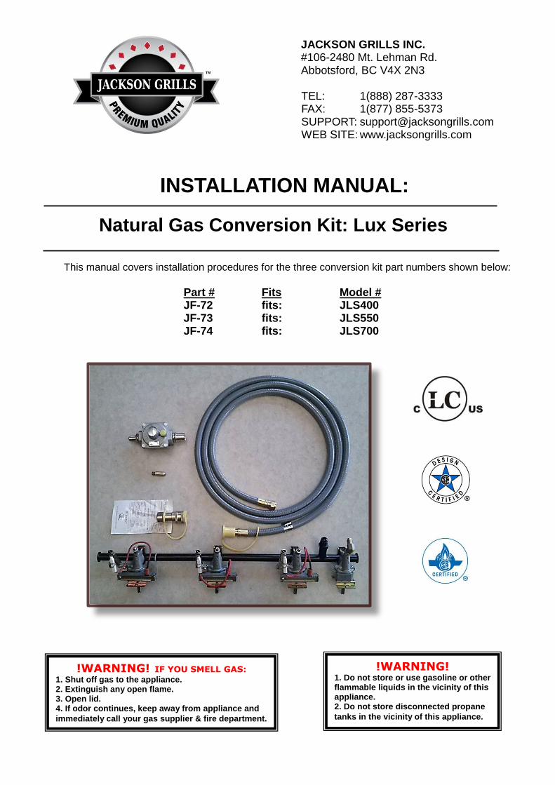
INSTALLATION MANUAL: This manual covers installation procedures for the three conversion kit part numbers shown below:
Part # Fits Model #
JF-72 fits: JLS400 JF-73 fits: JLS550 JF-74 fits: JLS700
Natural Gas Conversion Kit: Lux Series
JACKSON GRILLS INC. #106-2480 Mt. Lehman Rd. Abbotsford, BC V4X 2N3
TEL: 1(888) 287-3333 FAX: 1(877) 855-5373 SUPPORT: [email protected] WEB SITE: www.jacksongrills.com
!WARNING! IF YOU SMELL GAS: 1. Shut off gas to the appliance. 2. Extinguish any open flame. 3. Open lid. 4. If odor continues, keep away from appliance and
immediately call your gas supplier & fire department.
!WARNING! 1. Do not store or use gasoline or other flammable liquids in the vicinity of this appliance. 2. Do not store disconnected propane
tanks in the vicinity of this appliance.
Version: MAR13
CERTIFICATION & TESTING This conversion kit/manifold assembly has been tested by Labtest Certification (LC) and has been tested to ANSI Z21.58a-1198 & CGA 16a-M98, and Certified for Canada and the USA. NOTE: The use and installation of this product must conform to local codes. In the absence of local codes, use the National Fuel and Gas Code, ANSI A223.1, Storage and Handling of Liquefied Petroleum Gasses, NFPA / ANSI 58.
!SAFETY WARNINGS!
SAFETY FIRST:
Please read and understand all warnings and precautions prior to operating your Side Burner. 1 This accessory kit is for outside use only, and shall not be used in any building, garage, enclosed area or
vehicle. . 2 Do not use gasoline, alcohol or other volatiles for lighting purposes.. 3 Do not alter this Conversion Kit in any manner. 4 Do not attempt to install this kit until the Propane Cylinder has been shut off and disconnected from the grill. 5 Please note that propane (LP) is explosive under pressure, heavier than air, and settles and pools in low
areas, which can create an explosion hazard. Exercise caution when disconnecting and storing the Propane Cylinder.
6 Caution: contact with propane gas can cause freeze burns to your skin.
7 Once the Conversion Kit has been installed, all connections must be soap tested to ensure that there are no
Natural Gas leaks.
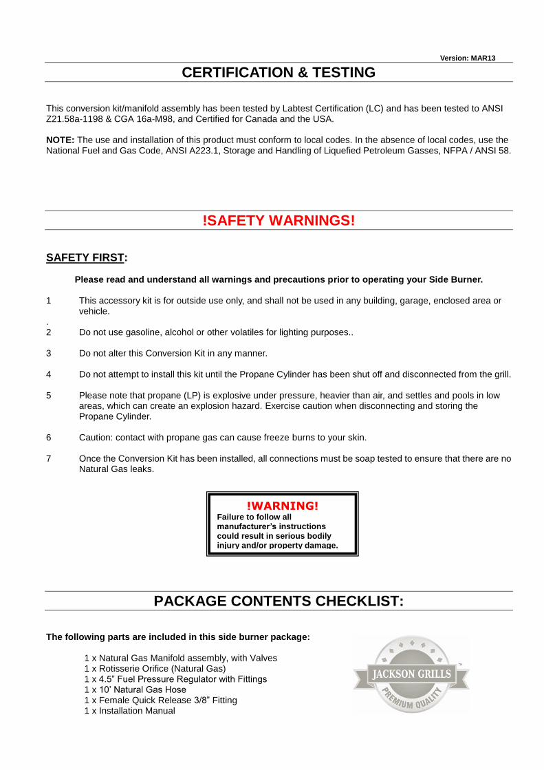
PACKAGE CONTENTS CHECKLIST: The following parts are included in this side burner package:
1 x Natural Gas Manifold assembly, with Valves 1 x Rotisserie Orifice (Natural Gas) 1 x 4.5” Fuel Pressure Regulator with Fittings 1 x 10’ Natural Gas Hose 1 x Female Quick Release 3/8” Fitting 1 x Installation Manual
!WARNING! Failure to follow all manufacturer’s instructions could result in serious bodily injury and/or property damage.
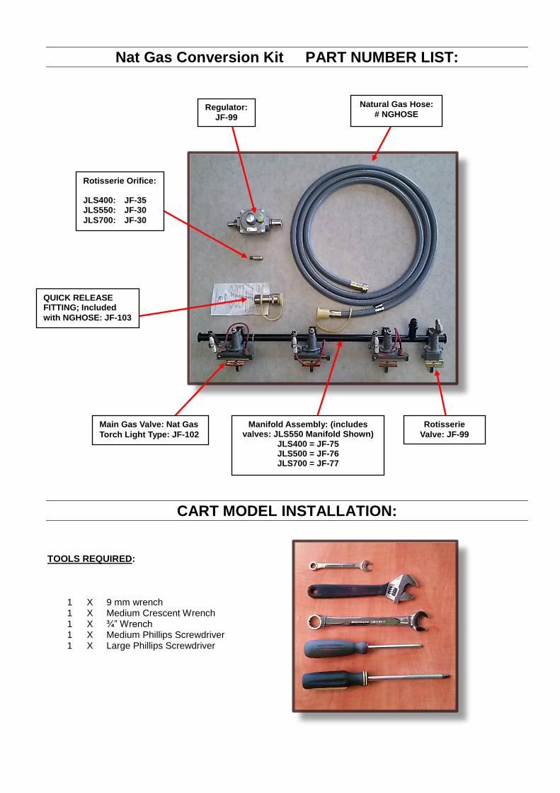
Natural Gas Hose:
# NGHOSE Regulator:
JF-99
QUICK RELEASE FITTING; Included
with NGHOSE: JF-103
Rotisserie Orifice: JLS400: JF-35 JLS550: JF-30
JLS700: JF-30
Manifold Assembly: (includes valves: JLS550 Manifold Shown)
JLS400 = JF-75 JLS500 = JF-76 JLS700 = JF-77
Main Gas Valve: Nat Gas
Torch Light Type: JF-102
Rotisserie
Valve: JF-99
Nat Gas Conversion Kit PART NUMBER LIST:
CART MODEL INSTALLATION: TOOLS REQUIRED:
1 X 9 mm wrench 1 X Medium Crescent Wrench 1 X ¾” Wrench 1 X Medium Phillips Screwdriver 1 X Large Phillips Screwdriver

Figure 1
Figure 2
Figure 3
Figure 4
STEP 1 Shut off Propane Cylinder valve, and remove Propane Hose and Regulator (Fig.1). Store propane tank with valve turned off and capped, in a well-ventilated exterior location. STEP 2 Lift out Grids and Diffuser Plates and set aside (Fig. 2) . STEP 3 Remove Main Burner Clips, Remove all Main Burners, and set aside (Fig. 3). STEP 4 Remove 2 x Phillips screws located on the inner far left of the BBQ oven, immediately behind the instruction panel slot (Fig. 4).
!WARNING! SHUT OFF FUEL before installing this Conversion Kit

Figure 8
Figure 5
Figure 6
STEP 5 Remove 2 x Phillips screws on underneath the console, on the far right and far left sides (Fig. 5 & 6)
STEP 6 Remove all Knobs by simply pulling up off the stems. Next, remove all the Bezels, by removing 2 Phillips screws per Bezel. STEP 7 Lift Console up and off the main oven, thus exposing the manifold and valves (Fig. 8). STEP 8 Undo the rotisserie electrode wire, by gently pulling it out of module. Do NOT tug on the wire itself, instead apply the force to the connector; otherwise the wire may break off the connector. (Fig. 9).
{Shown with rotisserie ignition module removed from for clarity.}
Rev Feb 2012
Figure 9

!TECH. TIP! DO NOT over tighten orifice: orifice may break off if over-tightened.
!TECH. TIP! A small amount of gas rated pipe tape or pipe dope must be used on the orifice threads; avoid inadvertently blocking the orifice as this could affect cooking performance.
!TECH. TIP! Avoid over tightening the rotisserie fuel line: this could cause the valve to cracking or break in half.
STEP 9 Disconnect Main Fuel Line and Rotisserie Fuel Line (Fig. 10, 11). Set aside complete propane Manifold Assembly.
STEP 10 Remove 4 Phillips screws to open Rotisserie Orifice Access Panel, and remove Rotisserie Orifice, using a 9mm wrench. (Fig.12a,12b). STEP 11 Install Natural Gas Manifold assembly, Console, Bezels, and Knobs by reversing Steps 4-9 Above. STEP 12 Install Rotisserie Orifice; use a small amount of Pipe Sealant on threads. Line (Fig. 12a, 12b).
Figure 10
Figure 11
Figure 12a
Figure 12b

!WARNING! Soap Test all connections after the conversion is completed. Turn gas on only AFTER this. Gas leaks are a Fire Hazard; injury and property damage may result
STEP 13 Reinstall the diffusers and cook grids. STEP 14 To complete the conversion, install the Natural Gas Hose on the fitting from which the LP hose was removed (See Step 3). STEP 15 Soap Test ALL connections to ensure that there are no gas leaks (Fig. 13).
Figure 13