installation manual · installation manual system air conditioners models 〈branch selector...
TRANSCRIPT

INSTALLATION MANUAL
System Air Conditioners
MODELS⟨Branch Selector unit⟩
BS4Q54TVJ BS10Q54TVJ BS6Q54TVJ BS12Q54TVJ BS8Q54TVJ
READ THESE INSTRUCTIONS CAREFULLY BEFORE INSTALLATION. KEEP THIS MANUAL IN A HANDY PLACE FOR FUTURE REFERENCE.
LIRE SOIGNEUSEMENT CES INSTRUCTIONS AVANT L’INSTALLATION. CONSERVER CE MANUEL A PORTEE DE MAIN POUR REFERENCE ULTERIEURE.
LEA CUIDADOSAMENTE ESTAS INSTRUCCIONES ANTES DE INSTALAR. GUARDE ESTE MANUAL EN UN LUGAR A MANO PARA LEER EN CASO DE TENER ALGUNA DUDA.
English
Français
Español
3P405106-9
00_CV_3P405106-9.indd 1 4/20/2015 3:08:13 PM

3P405106-9 Englishi
Safety considerationsRead these Safety considerations for Installation carefully be-fore installing an air conditioner or heat pump. After complet-ing the installation, make sure that the unit operates properly during the startup operation.Instruct the customer on how to operate and maintain the unit.Inform customers that they should store this Installation Manual with the Operation Manual for future reference.Always use a licensed installer or contractor to install this product.Improper installation can result in water or refrigerant leak-age, electrical shock, fire, or explosion.Meanings of DANGER, WARNING, CAUTION, and NOTESymbols:
DANGER . . . . . . . . Indicates an imminently hazardous situation which, if not avoided, will result in death or serious injury.
WARNING . . . . . . . Indicates a potentially hazardous situation which, if not avoided, could result in death or serious injury.
CAUTION . . . . . . . . Indicates a potentially hazardous situation which, if not avoided, may result in minor or moderate injury. It may also be used to alert against unsafe practices.
NOTE . . . . . . . . . . . Indicates situations that may result in equipment or property-damage accidents only.
INFORMATION . . . This symbol identifies useful tips or additional information.
DANGER• Refrigerant gas is heavier than air and replaces oxygen. A
massive leak will result in oxygen depletion, especially in basements, and an asphyxiation hazard will result in seri-ous injury or death.
• Do not ground units to water pipes, gas pipes, telephone wires, or lightning rods as incomplete grounding will result a severe shock hazard resulting in severe injury or death. Additionally, grounding to gas pipes will result a gas leak and potential explosion resulting in severe injury or death.
• If refrigerant gas leaks during installation, ventilate the area immediately. Refrigerant gas will result in producing toxic gas if it comes into contact with fire. Exposure to this gas will result in severe injury or death.
• After completing the installation work, check that the re-frigerant gas does not leak throughout the system.
• Do not install unit in an area where flammable materials are present due to risk of explosions that will result in seri-ous injury or death.
• Safely dispose all packing and transportation materials in accordance with federal/state/local laws or ordinances. Packing materials such as nails and other metal or wood parts, including plastic packing materials used for trans-portation will result in injuries or death by suffocation.
WARNING• Only qualified personnel must carry out the installation
work. Installation must be done in accordance with this installation manual. Improper installation could result in water leakage, electric shock, or fire.
• When installing the unit in a small room, take measures to keep the refrigerant concentration from exceeding allow-able safety limits. Excessive refrigerant leaks, in the event of an accident in a closed ambient space, could result in oxygen deficiency.
• Use only specified accessories and parts for installation work. Failure to use specified parts could result in water leakage, electric shocks, fire, or the unit falling.
• Install the air conditioner or heat pump on a foundation strong enough that it can withstand the weight of the unit. A foundation of insufficient strength could result in the unit falling and causing injuries.
• Take into account strong winds, typhoons, or earthquakes when installing. Improper installation could result in the unit falling and causing accidents.
• Make sure that a separate power supply circuit is pro-vided for this unit and that all electrical work is carried out by qualified personnel according to local, state and national regulations. An insufficient power supply capacity or improper electrical construction could result in electric shocks or fire.
• Make sure that all wiring is secured, that specified wires are used, and that no external forces act on the terminal connections or wires. Improper connections or installation could result in fire.
• When wiring, position the wires so that the control box cover can be securely fastened. Improper positioning of the control box cover could result in electric shocks, fire, or the terminals overheating.
• Before touching electrical parts, turn off the unit. • This equipment can be installed with a Ground-Fault Cir-
cuit Interrupter (GFCI). Although this is a recognized mea-sure for additional protection, with the grounding system in North America, a dedicated GFCI is not necessary.
• Securely fasten the unit terminal cover (panel). If the terminal cover/panel is not installed properly, dust or water may enter the outdoor unit and could result in fire or electric shock.
• When installing or relocating the system, keep the refriger-ant circuit free from substances other than the specified refrigerant (R410A) such as air. Any presence of air or oth-er foreign substance in the refrigerant circuit could result in abnormal pressure rise or rupture, resulting in injury.
• Do not change the setting of the protection devices. If the pressure switch, thermal switch, or other protection device is shorted and operated forcibly, or parts other than those specified by Daikin are used, fire or explosion could result.
01_EN_3P405106-9.indb 1 3/27/2015 1:53:07 PM

3P405106-9 English ii
CAUTION• Do not touch the switch with wet fingers. Touching a switch
with wet fingers may result in electric shock.• Do not allow children to play on or around the unit or it
may result in injury.• The heat exchanger fins are sharp enough to cut, and
may result in injury if improperly used. To avoid injury wear glove or cover the fins when working around them.
• Do not touch the refrigerant pipes during and immediately after operation as the refrigerant pipes may be hot or cold, depending on the condition of the refrigerant flow-ing through the refrigerant piping, compressor, and other refrigerant cycle parts. It may result in your hands get-ting burns or frostbite if you touch the refrigerant pipes. To avoid injury, give the pipes time to return to normal temperature or, if you must touch them, be sure to wear proper gloves.
• Insulate piping to prevent condensation.• Be careful when transporting the product.• Do not turn off the power immediately after stopping
operation. Always wait for at least 5 minutes before turning off the power. Otherwise, water leakage may result.
• Do not use a charging cylinder. Using a charging cylinder may cause the refrigerant to deteriorate.
• Refrigerant R410A in the system must be kept clean, dry, and tight.(a) Clean and Dry - Foreign materials (including mineral
oils such as SUNISO oil or moisture) should be pre-vented from getting into the system.
(b) Tight - R410A does not contain any chlorine, does not destroy the ozone layer, and does not reduce the earth’s protection again harmful ultraviolet radiation. R410A can contribute to the greenhouse effect if it is released. Therefore take proper measures to check for the tightness of the refrigerant piping installation. Read the chapter Refrigerant Piping and follow the procedures.
• Since R410A is a blend, the required additional refriger-ant must be charged in its liquid state. If the refrigerant is charged in a state of gas, its composition can change and the system will not work properly.
• The indoor unit is for R410A. See the catalog for indoor models that can be connected. Normal operation is not possible when connected to other units.
• Remote controller (wireless kit) transmitting distance can be shorter than expected in rooms with electronic fluores-cent lamps (inverter or rapid start types). Install the indoor unit far away from fluorescent lamps as much as possible.
• Indoor units are for indoor installation only. Outdoor units can be installed either outdoors or indoors. This unit is for indoor use.
• Do not install the air conditioner or heat pump in the fol-lowing locations:(a) Where a mineral oil mist or oil spray or vapor is pro-
duced, for example, in a kitchen.Plastic parts may deteriorate and fall off and thus may result in water leakage.
(b) Where corrosive gas, such as sulfurous acid gas, is produced.Corroding copper pipes or soldered parts may result in refrigerant leakage.
(c) Near machinery emitting electromagnetic waves.
Electromagnetic waves may disturb the operation of the control system and cause the unit to malfunction.
(d) Where flammable gas may leak, where there is car-bon fiber, or ignitable dust suspension in the air, or where volatile flammables such as thinner or gasoline are handled. Operating the unit in such conditions may result in a fire.
• Take adequate measures to prevent the outdoor unit from being used as a shelter by small animals. Small animals making contact with electrical parts may result in malfunc-tions, smoke, or fire. Instruct the customer to keep the area around the unit clean.
NOTE• Install the power supply and transmission wires for the in-
door and outdoor units at least 3.5 ft. (1 m) away from tele-visions or radios to prevent image interference or noise. Depending on the radio waves, a distance of 3.5 ft. (1 m) may not be sufficient to eliminate the noise.
• Dismantling the unit, treatment of the refrigerant, oil and additional parts must be done in accordance with the relevant local, state, and national regulations.
• Do not use the following tools that are used with con-ventional refrigerants: gauge manifold, charge hose, gas leak detector, reverse flow check valve, refrigerant charge base, vacuum gauge, or refrigerant recovery equipment.
• If the conventional refrigerant and refrigerator oil are mixed in R410A, the refrigerant result in deterioration.
• This air conditioner or heat pump is an appliance that should not be accessible to the general public.
• As design pressure is 478 psi (3.3 MPa), the wall thick-ness of field-installed pipes should be selected in accor-dance with the relevant local, state, and national regula-tions.
Codes and RegulationsThis product is designed and manufactured to comply with national codes. Installation in accordance with such codes and/or prevailing local codes/regulations is the responsibility of the installer. The manufacturer assumes no responsibility for equipment installed in violation of any codes or regula-tions. Rated performance is achieved after 72 hours of opera-tion.
01_EN_3P405106-9.indb 2 3/27/2015 1:53:08 PM

BS4Q54TVJBS6Q54TVJBS8Q54TVJ
BS10Q54TVJBS12Q54TVJ VRVIV System Air Conditioners Installation manual
1 3P405106-9 English
CONTENTSSafety considerations ............................................................................................................iCodes and Regulations ........................................................................................................ ii1. BEFORE INSTALLATION ...............................................................................................22. SELECTING INSTALLATION SITE .................................................................................43. PREPARATIONS BEFORE INSTALLATION ...................................................................54. BRANCH SELECTOR UNIT INSTALLATION .................................................................55. REFRIGERANT PIPING WORK .....................................................................................66. ELECTRIC WIRING WORK ..........................................................................................117. INITIAL SETTING .........................................................................................................178. ADDING AN ADDITIONAL CHARGE OF REFRIGERANT ..........................................189. CHECK OPERATION AND TEST OPERATION ...........................................................18
The original instructions are written in English. All other languages are translations of the original instruc-tions.
01_EN_3P405106-9.indb 1 3/27/2015 1:53:08 PM

1. BEFORE INSTALLATION
1-1 Precautions
• Be sure to verify in advance that the refrigerant used in installation work is R410A. The unit will not operate correctly with a different type of refrigerant.
• When moving the unit during or after unpacking, hold it using the 4 hanging brackets and avoid subjecting other parts, particularly refrigerant pipes and the control box, to force.
• For more information about installation of outdoor and indoor units, refer to the installation manual that came with each unit.
1-2 Accessories
• Verify that the following accessories have been included in the packaging.
Important Do not throw away any accessories that may be needed in installation work until installation is complete.
Name Clamps (1) Insulation tube (2) Vinyl tube (3)
Quantity
BS4Q54TVJ 23 pcs. 4 pcs. 4 pcs.
1 pc.BS6Q54TVJ 32 pcs. 6 pcs. 6 pcs.BS8Q54TVJ 40 pcs. 8 pcs. 8 pcs.BS10Q54TVJ 49 pcs. 10 pcs. 10 pcs.BS12Q54TVJ 57 pcs. 12 pcs. 12 pcs.
Shape
(1) (2)-1 (2)-2 (3)
(Thin) (Thick)
Name Stopper pipes (4) Insulation tube for stopper pipes (5) Documentation
Quantity
BS4Q54TVJ
1 copyBS6Q54TVJ
1 pc. 1 pc. 1 pc. 1 pc.BS8Q54TVJBS10Q54TVJBS12Q54TVJ
Shape
(4)-1 (4)-2 (5)-1 (5)-2
Installation Manual
f3/8 in. (f9.5 mm) f5/8 in. (f15.9 mm) (Thin) (Thick)
NOTES • You will need a reducing joint (to be supplied in the field) if the diameter of the pipe on site as
described in the outdoor unit’s installation manual or equipment design materials does not match the diameter of the connection pipe on the outdoor side of the Branch Selector unit.
• Thermal insulation for connection pipes on the outdoor unit side must be supplied in the field.
23P405106-9 English
01_EN_3P405106-9.indb 2 3/27/2015 1:53:08 PM

1-3 Combination
• This Branch Selector unit is only for systems for models REYQ-T and PC series. It cannot be connected to systems for models REYQ-M, P, PA and PB series.
• For series of applicable indoor units, refer to the catalog or other literature.• Select the Branch Selector unit to fit the total capacity (sum of unit’s capacity) of the indoor units
to be connected downstream, refer to the Table 1. About indoor unit’s capacity, refer to the Table 2.
Table 1 Model Total capacity of all downstream indoor units
BS4Q54TVJ A ≤ 144 (*)BS6Q54TVJ A ≤ 216 (*)BS8Q54TVJ BS10Q54TVJ BS12Q54TVJ
A ≤ 290 (*)
* The total capacity and number of indoor units connectable to each branch connector are up to 54 and 5, respectively. When the total capacity of indoor units to be connected downstream is larger than 54 (MAX. 96), use a junction pipe kit (KHRP26A250T, sold separately) to join two connections downstream from the Branch Selector unit.
Table 2
Capacity expressed as indoor unit’s model No. 07 09 12 18 24 30 36 42 48 54 72 96Indoor unit’s capacity (for use in computation) 7.5 9.5 12 18 24 30 36 42 48 54 72 96
<Example selection> In case of the Branch Selector unit with connect a FXFQ12P and a FXMQ18P. Total capacity = 12+18 = 30
1-4 ChecklistExercise particular care concerning the following items during installation work and check again after installation is complete:
Post-installation checklistChecklist If defective Check here.
Has the Branch Selector unit been installed securely? The unit may fall, vibrate, or operate noisily.
Did you conduct a gas leak inspection? The unit may fail to heat or cool as designed.Was the unit fully insulated? (Refrigerant pipes) The unit may leak water.Is the supply voltage the same as the voltage indicated on the label?
The unit may fail to operate or burn up.
Are there any wiring mistakes or erroneous wiring or erroneous pipe connections?
The unit may fail to operate, burn up, or produce abnormal noise.
Has the unit been grounded?The unit may pose a hazard in the event of a short-circuit.
Is the thickness of the electrical wiring the same as described in the specifications?
The unit may fail to operate or burn up.
Delivery checklistChecklist Check here.
Has a cover been installed on the control box?Did you give the customer the installation manual?
3 3P405106-9 English
01_EN_3P405106-9.indb 3 3/27/2015 1:53:08 PM
2. SELECTING INSTALLATION SITE
Consider the following requirements when choosing the installation location and obtain the cus-tomer’s consent:
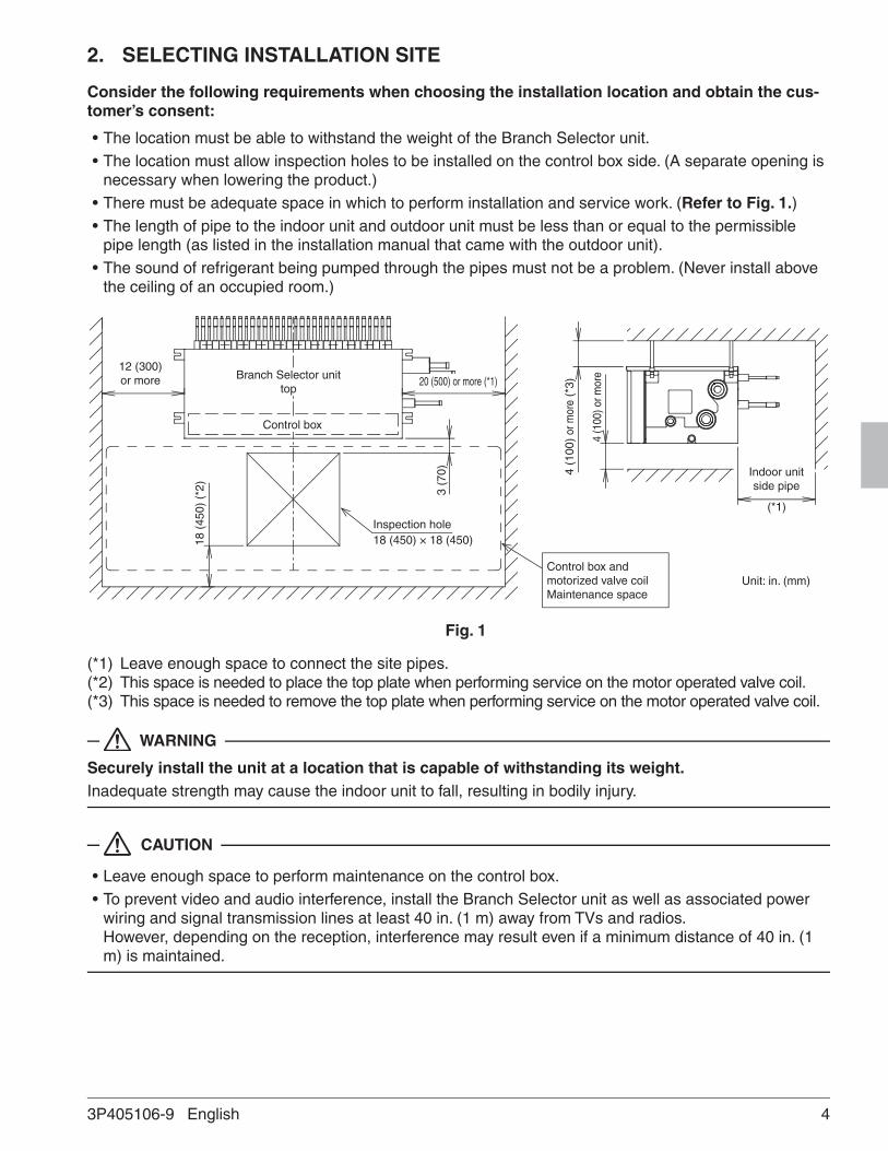
• The location must be able to withstand the weight of the Branch Selector unit.• The location must allow inspection holes to be installed on the control box side. (A separate opening is
necessary when lowering the product.)• There must be adequate space in which to perform installation and service work. (Refer to Fig. 1.)• The length of pipe to the indoor unit and outdoor unit must be less than or equal to the permissible
pipe length (as listed in the installation manual that came with the outdoor unit).• The sound of refrigerant being pumped through the pipes must not be a problem. (Never install above
the ceiling of an occupied room.)
Inspection hole
Branch Selector unittop
18 (450) × 18 (450)
3 (7
0)
12 (300) or more 20 (500) or more (*1)
18 (
450)
(*2
)
Control box
4 (1
00)
or m
ore
(*3)
4 (1
00) o
r mor
e
Control box and motorized valve coilMaintenance space
Indoor unit side pipe
(*1)
Unit: in. (mm)
Fig. 1
(*1) Leave enough space to connect the site pipes.(*2) This space is needed to place the top plate when performing service on the motor operated valve coil. (*3) This space is needed to remove the top plate when performing service on the motor operated valve coil.
WARNING
Securely install the unit at a location that is capable of withstanding its weight.Inadequate strength may cause the indoor unit to fall, resulting in bodily injury.
CAUTION
• Leave enough space to perform maintenance on the control box.• To prevent video and audio interference, install the Branch Selector unit as well as associated power
wiring and signal transmission lines at least 40 in. (1 m) away from TVs and radios. However, depending on the reception, interference may result even if a minimum distance of 40 in. (1 m) is maintained.
43P405106-9 English
01_EN_3P405106-9.indb 4 3/27/2015 1:53:09 PM

3. PREPARATIONS BEFORE INSTALLATIONInstall suspension bolts and hanging brackets as illustrated in the diagram below.• Use a suspension bolt size of 3/8 in.(M8) to 7/16 in.(M10).• Use mold-in inserts and embedded foundation bolts for new installations or hole-in anchor bolts or
similar hardware for existing installations, taking care to install in a manner that can withstand the unit’s weight.
Unit: in. (mm)Branch Selector unit A
BS4Q54TVJ 16-5/16 (415)BS6Q54TVJ
24-5/8 (625)BS8Q54TVJBS10Q54TVJ
34-1/16 (865)BS12Q54TVJ
A 12-1/8 (308)
<Suspension bolt spacing>
• Use the hanging brackets to support the connection pipes on both the front and back of the unit within 40 in. (1 m) of the unit’s side. Placing an excessive amount of weight on the Branch Selector unit's hanging brackets may cause the unit to fall, resulting in bodily injury.
SlabAnchor bolt
Long nut or turnbuckleSuspension bolt
Within 40 in. (1 m)
UnitConnection pipe
Note: All the above parts must be supplied in the field
<Example installation>
4. BRANCH SELECTOR UNIT INSTALLATIONUse only accessories and parts that conform to the designated specifications when installing the unit.
1. Position the Branch Selector unit and secure it temporarily in place. Attach the hanging brackets to the suspension bolts as per the instructions in the figure to the right. Be sure to affix nuts (3/8 in.(M8) or 7/16 in.(M10), 3 pieces in 4 locations) and washers (for 3/8 in.(M8), outside diameter of 15/16 in. (24 mm) to 1-1/8 in. (28 mm) or for 7/16 in.(M10), outside diameter of 1-3/16 in. (30 mm) to 1-5/16 in. (34 mm): 2 pieces in 4 locations) (to be supplied in the field) from both the top and bottom of the hanging brackets on both sides of the unit to secure it in place.
2. Adjust the height of the unit as desired.3. Using a level, verify that the unit has been installed in a level
orientation.
Nut (double nut) (Field supply)
Suspension bolt (Field supply)
3/8-9/16 in. (10 - 15 mm)
Hanging bracket
Washer (Field supply)
Nut (Field supply)
Branch Selector unit
WARNING
• Install the Branch Selector unit in a level orientation.• Attach nuts on both the top and bottom of the hanging brackets.
Overtightening the lower nut without the upper nut in place may cause the hanging bracket and top plate to deform, causing the unit to produce abnormal noise.
5 3P405106-9 English
01_EN_3P405106-9.indb 5 3/27/2015 1:53:09 PM
5. REFRIGERANT PIPING WORK
• For instructions for installing piping between the outdoor unit and the Branch Selector unit, selecting a refrigerant branch kit, and installing piping between the refrigerant branch kit and indoor units, refer to the installation manual and included with the outdoor unit.
• Before beginning the work, be sure to verify that the type of refrigerant used is R410A. (The unit will not operate correctly with a different type of refrigerant.)
• Insulate all of the piping, including the liquid pipes, high/low pressure gas pipes, suction gas pipes, gas pipes, and the pipe connections for these. Not insulating these pipes could result in water leaks or burns. In particular, low-temperature gas flows in the high/low pressure gas piping during full cooling opera-tion, so the same amount of insulation as used for the suction gas pipes is required. In addition, high-temperature gas flows in the high/low pressure gas piping and gas piping, so use insulation that can withstand more than 250°F (120°C).
• Select insulation material as necessary for the installation environment. For details, refer to the Engineering Data Book. If you fail to do so, condensation could form on the surface of the insulation.
5-1 Pipe size selection
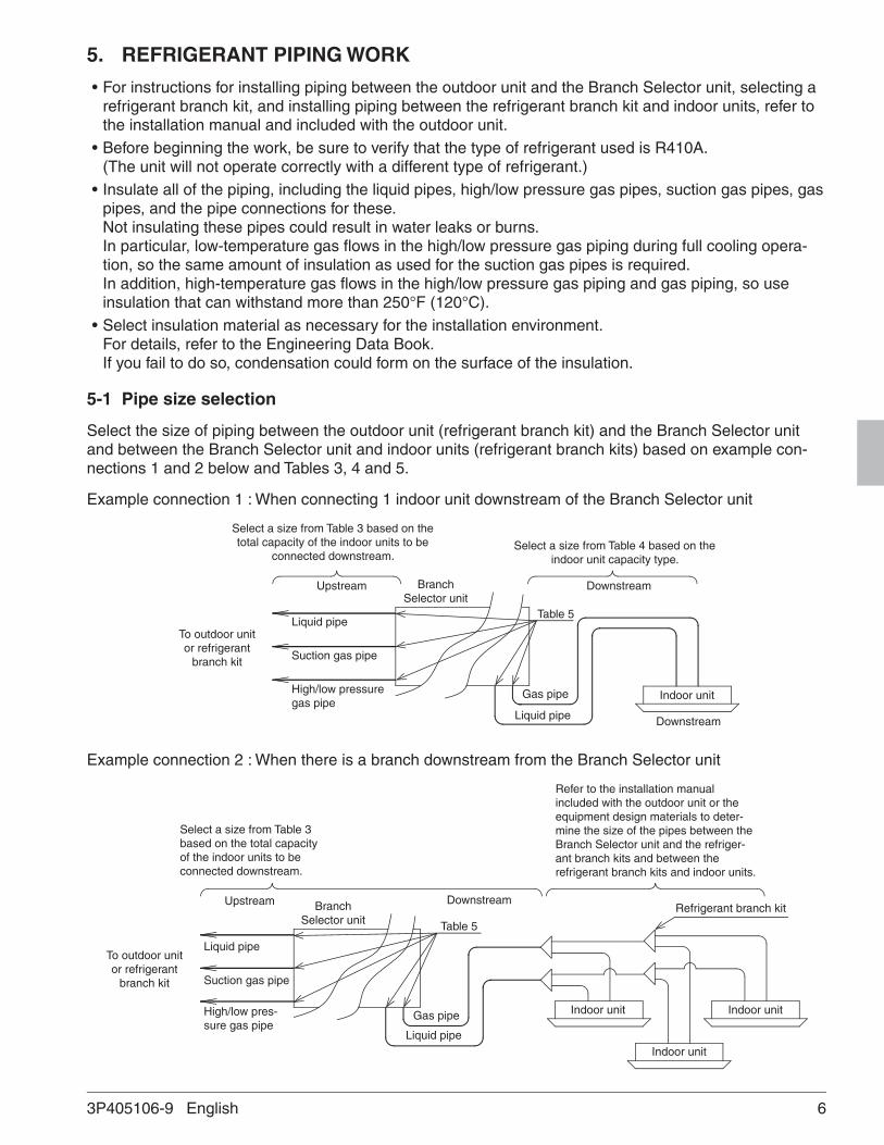
Select the size of piping between the outdoor unit (refrigerant branch kit) and the Branch Selector unit and between the Branch Selector unit and indoor units (refrigerant branch kits) based on example con-nections 1 and 2 below and Tables 3, 4 and 5.
Example connection 1 : When connecting 1 indoor unit downstream of the Branch Selector unit
Upstream Downstream
Downstream
Indoor unit
Branch Selector unit
Liquid pipe
Suction gas pipe
High/low pressure gas pipe
Liquid pipe
Gas pipe
To outdoor unit or refrigerant
branch kit
Table 5
Select a size from Table 3 based on the total capacity of the indoor units to be
connected downstream. Select a size from Table 4 based on the
indoor unit capacity type.
Example connection 2 : When there is a branch downstream from the Branch Selector unit
Select a size from Table 3 based on the total capacity of the indoor units to be connected downstream.
Refer to the installation manual included with the outdoor unit or the equipment design materials to deter-mine the size of the pipes between the Branch Selector unit and the refriger-ant branch kits and between the refrigerant branch kits and indoor units.
Upstream
Liquid pipe
Suction gas pipe
High/low pres-sure gas pipe
Branch Selector unit
Downstream
Indoor unit Indoor unit
Indoor unit
Refrigerant branch kit
Liquid pipe
Gas pipe
Table 5
To outdoor unit or refrigerant
branch kit
63P405106-9 English
01_EN_3P405106-9.indb 6 3/27/2015 1:53:09 PM

Table 3 Total indoor unit capacity and pipe size
Total indoor unit capacity (x)
Pipe size (Outside diameter)Upstream Downstream
Suction High/low pressure Liquid Gas pipe Liquid pipein. mm in. mm in. mm in. mm in. mm
x < 54 f5/8 f15.9 f1/2 f12.7f3/8 f9.5
f5/8 f15.9f3/8 f9.554 ≤ x < 72 f3/4 f19.1 f5/8 f15.9 f3/4 f19.1
72 ≤ x < 111 f7/8 f22.2f3/4 f19.1
f7/8 f22.2111 ≤ x < 162
f1-1/8 f28.6f1/2 f12.7
162 ≤ x < 230f1-1/8 f28.6
f5/8 f15.9230 ≤ x ≤ 290 f1-3/8 f34.9 f3/4 f19.1
• In case of connection to the main pipe, refer to the installation manual included with the outdoor unit or the equipment design materials.
Table 4 Indoor unit connection pipe size
Indoor unit capacity sizePipe size (Outside diameter)
Gas pipe Liquid pipein. mm in. mm
07, 09, 12, 18 f1/2 f12.7 f1/4 f6.424, 30, 36, 42, 48, 54 f5/8 f15.9
f3/8 f9.572 f3/4 f19.196 f7/8 f22.2
• Table 5 lists Branch Selector unit connection pipe size.
Table 5 Branch Selector unit connection pipe size Outdoor unit side (*1)
Branch Selector unitSuction pipe High/low pressure gas pipe Liquid pipe
in. mm in. mm in. mmBS4Q54TVJ f7/8 f22.2
f3/4 f19.1
f3/8 f9.5
BS6Q54TVJ
f1-1/8 f28.6f1/2 f12.7
BS8Q54TVJBS10Q54TVJ
f1-1/8 f28.6 f5/8 f15.9BS12Q54TVJ
Indoor unit side (*2)
Branch Selector unitGas pipe Liquid pipe
in. mm in. mmBS4Q54TVJ
f1/2 (f5/8) f12.7 (f15.9) f1/4 (f3/8) f6.4 (f9.5)BS6Q54TVJBS8Q54TVJBS10Q54TVJBS12Q54TVJ
*1 If the pipe size differs from that of the size selected from Table 3, you will need a reducing joint (to be supplied in the field).
*2 The pipe diameter in parentheses can be used by cutting the pipes on the Branch Selector unit side with a pipe cutter. For details, refer to “5-3 Piping connection.”
7 3P405106-9 English
01_EN_3P405106-9.indb 7 3/27/2015 1:53:09 PM
NOTES • If the number of indoor units to be connected is less than the number of branch ports (so that there are
empty branch ports left, or if you plan to increase the number in the future), any of the branch ports can be left open.
• If you plan to add new indoor units in the future, select a pipe size based on the total indoor unit capac-ity before addition of new units.
• For more information about how to install the stop valve kit for extension, refer to the installation man-ual included with the stop valve kit for extension.
5-2 Pipe connection work precautions
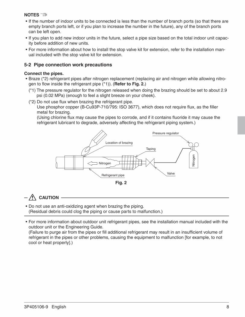
Connect the pipes.• Braze (*2) refrigerant pipes after nitrogen replacement (replacing air and nitrogen while allowing nitro-
gen to flow inside the refrigerant pipe (*1)). (Refer to Fig. 2.)(*1) The pressure regulator for the nitrogen released when doing the brazing should be set to about 2.9
psi (0.02 MPa) (enough to feel a slight breeze on your cheek).(*2) Do not use flux when brazing the refrigerant pipe.
Use phosphor copper (B-Cu93P-710/795: ISO 3677), which does not require flux, as the filler metal for brazing. (Using chlorine flux may cause the pipes to corrode, and if it contains fluoride it may cause the refrigerant lubricant to degrade, adversely affecting the refrigerant piping system.)
Location of brazing
Nitrogen
Refrigerant pipe Valve
Taping
Nitr
ogen
Pressure regulator
Fig. 2
CAUTION
• Do not use an anti-oxidizing agent when brazing the piping. (Residual debris could clog the piping or cause parts to malfunction.)
• For more information about outdoor unit refrigerant pipes, see the installation manual included with the outdoor unit or the Engineering Guide. (Failure to purge air from the pipes or fill additional refrigerant may result in an insufficient volume of refrigerant in the pipes or other problems, causing the equipment to malfunction [for example, to not cool or heat properly].)
83P405106-9 English
01_EN_3P405106-9.indb 8 3/27/2015 1:53:10 PM

5-3 Piping connection
Liquid pipe (*1)
Suction gas pipe (*1)
High/low pressure gas pipe (*1)
Branch Selector unit (top)
Unit D Unit C Unit B Unit A
Liquid pipe (*1)Gas pipe (*1)
Reducing joint (*2)
NotesIn case of connecting with a 07-18 type indoor unit, there is no need to cut and connect as it is. In case of others, cut the outlet pipe and connect to the connecting pipe. In accordance with the following instructions.
Cutting point (Center of connection area)
Connect
Local pipe
Connection area
(*1) Indicates local pipe.(*2) Reducing joint may be required (field supply) if the local pipe size does not suit on the pipe size of
the Branch Selector unit (Table 5).
If there are branch ports left unused (not connected to an indoor unit)• If there are unused branch ports, use stopper pipe (4) (accessory).
If there are numerous unused branch ports, be sure to use the stop pipe kit (KHFP26A100C).
5-4 Airtightness test and vacuum drying
• After completing refrigerant piping work for the indoor units, Branch Selector unit, and outdoor unit, conduct an airtightness test and vacuum drying. For more information about the airtightness test pressure, refer to the outdoor unit’s installation man-ual.
9 3P405106-9 English
01_EN_3P405106-9.indb 9 3/27/2015 1:53:10 PM

5-5 Piping insulation
• After the gas leak inspection is completed, refer to the following figures and use the included insulation tube (2) and clamps (1) to apply the insulation.
Liquid pipe
Suction gas pipe
High/low pressure gas pipe
Gas pipe
Liquid pipe
Indoor unit sideO
utdo
or u
nit s
ide
Branch Selector unit
CAUTION
• Insulate all of the piping including the liquid pipes, high/low pressure gas pipes, suction gas pipes, gas pipes, and the pipe connections for these. Not insulating these pipes could result in water leaks or burns. In particular, low-temperature gas flows in the high/low pressure gas pipes during full cooling opera-tion, so the same amount of insulation as used for the suction gas pipes is required. In addition, high-temperature gas flows in the high/low pressure gas piping and gas piping, so use insulation that can withstand more than 250°F (120°C).
• When reinforcing the insulation material in accordance with the installation environment, also reinforce the insulation on the piping protruding from the unit. Insulation material required for reinforcement work should be supplied in the field. For more information, refer to the Engineering Data Book.
2) Attach the insulation material. (Field supply)
1) Attach the insulation material. (Field supply)
3) Use the clamps (Field supply) to hold both ends.
Product
Adhere.
Product
2) Attach the insulation material. (Field supply)
3) Use the clamps (Field supply) to hold both ends.
1) Attach the insulation material. (Field supply)
Insulation tube (included with product)
Adhere.
Insulation material installation instructions (outdoor unit side) (liquid pipes)
Insulation material installation instructions (outdoor unit side)
(suction and high/low pressure gas pipes)
103P405106-9 English
01_EN_3P405106-9.indb 10 3/27/2015 1:53:10 PM
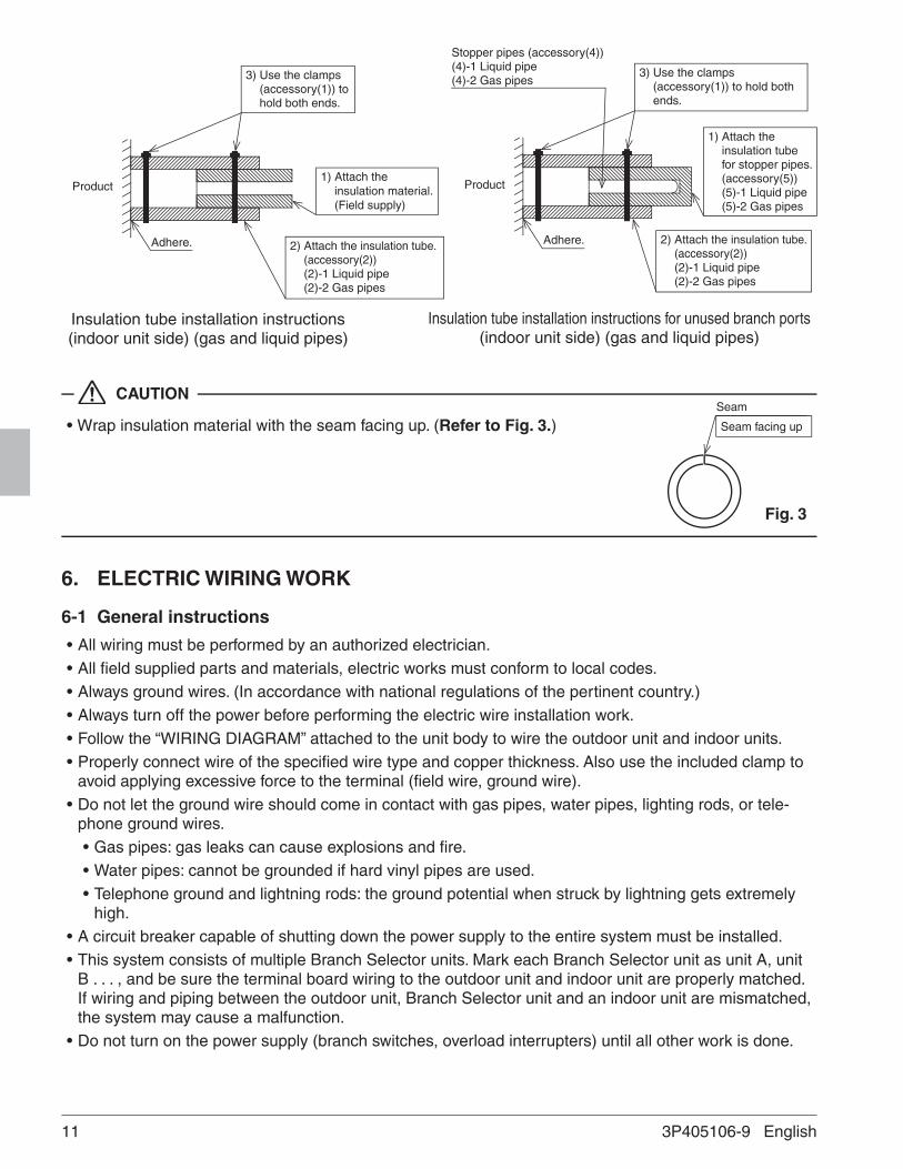
Product
2) Attach the insulation tube. (accessory(2)) (2)-1 Liquid pipe (2)-2 Gas pipes
1) Attach the insulation material. (Field supply)
3) Use the clamps (accessory(1)) to hold both ends.
Insulation tube installation instructions (indoor unit side) (gas and liquid pipes)
Adhere.
Product
2) Attach the insulation tube. (accessory(2)) (2)-1 Liquid pipe (2)-2 Gas pipes
3) Use the clamps (accessory(1)) to hold both ends.
Insulation tube installation instructions for unused branch ports (indoor unit side) (gas and liquid pipes)
Adhere.
Stopper pipes (accessory(4)) (4)-1 Liquid pipe (4)-2 Gas pipes
1) Attach the insulation tube for stopper pipes. (accessory(5)) (5)-1 Liquid pipe (5)-2 Gas pipes
CAUTION
• Wrap insulation material with the seam facing up. (Refer to Fig. 3.)
6. ELECTRIC WIRING WORK
6-1 General instructions
• All wiring must be performed by an authorized electrician.• All field supplied parts and materials, electric works must conform to local codes.• Always ground wires. (In accordance with national regulations of the pertinent country.)• Always turn off the power before performing the electric wire installation work.• Follow the “WIRING DIAGRAM” attached to the unit body to wire the outdoor unit and indoor units.• Properly connect wire of the specified wire type and copper thickness. Also use the included clamp to
avoid applying excessive force to the terminal (field wire, ground wire).• Do not let the ground wire should come in contact with gas pipes, water pipes, lighting rods, or tele-
phone ground wires.• Gas pipes: gas leaks can cause explosions and fire.• Water pipes: cannot be grounded if hard vinyl pipes are used.• Telephone ground and lightning rods: the ground potential when struck by lightning gets extremely
high.• A circuit breaker capable of shutting down the power supply to the entire system must be installed.• This system consists of multiple Branch Selector units. Mark each Branch Selector unit as unit A, unit
B . . . , and be sure the terminal board wiring to the outdoor unit and indoor unit are properly matched. If wiring and piping between the outdoor unit, Branch Selector unit and an indoor unit are mismatched, the system may cause a malfunction.
• Do not turn on the power supply (branch switches, overload interrupters) until all other work is done.
Seam
Seam facing up
Fig. 3
11 3P405106-9 English
01_EN_3P405106-9.indb 11 3/27/2015 1:53:11 PM

6-2 Example for the whole system
Power supply
Indoor unit
Indoor unit
Remote controller
Remote controller Remote controller
Power supply Outdoor unit
Main switch
Main switch
Power supply wiring
Transmission wiring
Circuit protection safety devices in accordance with local and national codes
BS4Q unit
BS4Q unit
Cooling-dedicated indoor unit
6-3 Power circuit, safety device and cable requirements• A power circuit (refer to Table 6) must be provided for connection of the unit. The circuit must be protected
with safety devices in accordance with local and national codes i.e a fuse, a circuit breaker or a GFCI.• When using residual current operated circuit breakers, be sure to use a high-speed type (0.1 second or
less) 30mA rated residual operating current.• Use copper conductors only.• Use insulated wire for the power cord.• Select the power supply cable type and size in accordance with relevant local and national regulations.• Use vinyl cord with sheath or cable (2 wire) of AWG 18 - 16 for transmission wiring.• The transmission wire lengths are as follows:
Between the Branch Selector unit and indoor units: Max. 3,280 ft. (1,000 m)Between the Branch Selector unit and outdoor unit: Max. 3,280 ft. (1,000 m)Between Branch Selector units: Max. 3,280 ft. (1,000 m)Total wiring length: 6,560 ft. (2,000 m) or less
Table 6
UnitsPower supply
Model Type Hz VoltageVoltage range
Min. Max. MCA MOPBS4Q54TVJ
VJ 60 208/230 187 253
0.4
15BS6Q54TVJ 0.6BS8Q54TVJ 0.8BS10Q54TVJ 1.0BS12Q54TVJ 1.2
MCA: Minimum Circuit Ampacity (A); MOP: Maximum Overcurrent Protective Device (A)
NOTES • The above Table 6 of electrical characteristics refers to one Branch Selector unit.
123P405106-9 English
01_EN_3P405106-9.indb 12 3/27/2015 1:53:11 PM
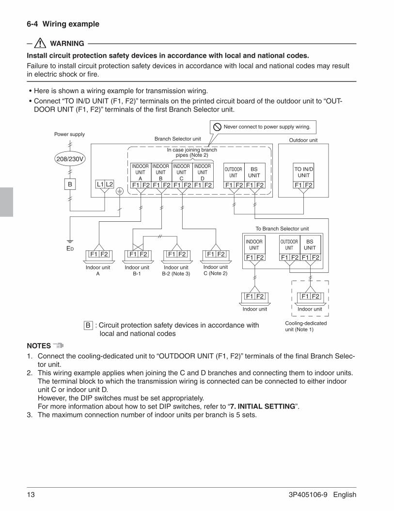
6-4 Wiring example
WARNING
Install circuit protection safety devices in accordance with local and national codes.Failure to install circuit protection safety devices in accordance with local and national codes may result in electric shock or fire.
• Here is shown a wiring example for transmission wiring.• Connect “TO IN/D UNIT (F1, F2)” terminals on the printed circuit board of the outdoor unit to “OUT-
DOOR UNIT (F1, F2)” terminals of the first Branch Selector unit.
F1 F2 F1 F2 F1 F2 F1 F2 F1 F2 F1 F2 F1 F2
F1 F2F1 F2
F1 F2F1 F2F1 F2F1 F2 F1 F2 F1 F2 F1 F2
L1B
ED
208/230V
L2
INDOOR UNIT
A
INDOOR UNIT
B
INDOOR UNIT
C
INDOOR UNIT
D
OUTDOOR UNIT
BS UNIT
Branch Selector unit Outdoor unit
To Branch Selector unit
Cooling-dedicated unit (Note 1)
Indoor unit A
Indoor unit B-1
Indoor unit B-2 (Note 3)
Indoor unit C (Note 2)
Indoor unit Indoor unit
TO IN/DUNIT
Never connect to power supply wiring.
In case joining branch pipes (Note 2)
INDOOR UNIT
OUTDOOR UNIT
BS UNIT
B : Circuit protection safety devices in accordance with local and national codes
Power supply
NOTES 1. Connect the cooling-dedicated unit to “OUTDOOR UNIT (F1, F2)” terminals of the final Branch Selec-
tor unit.2. This wiring example applies when joining the C and D branches and connecting them to indoor units.
The terminal block to which the transmission wiring is connected can be connected to either indoor unit C or indoor unit D. However, the DIP switches must be set appropriately. For more information about how to set DIP switches, refer to “7. INITIAL SETTING”.
3. The maximum connection number of indoor units per branch is 5 sets.
13 3P405106-9 English
01_EN_3P405106-9.indb 13 3/27/2015 1:53:11 PM

CAUTION
• Use 2-core transmission wiring. Using the same wire with 3 or more cores to connect 2 or more indoor units may cause them to stop with an error.
• When the shield wire is used, be sure to ground the one side of the shield wire. The total wiring length is 4,920 ft. (1,500m) when shielded wire is used.
• Be sure to use ring type crimp style terminals with insulation sleeves to connect wires to the power supply terminal block. (Refer to Fig. 4.)
• Do not use with the power supply terminal block and ground terminal connected to wiring for another circuit.
• Do not pre-solder stranded wire.• Connect wires securely so that the terminals will not be subjected to external force.• Use an appropriately sized screwdriver to tighten the terminal screws.
Use of a screwdriver that is too small could damage the screw head and prevent proper tightening.• Overtightening the terminal screws could damage the screw.
Refer to the table for the terminal screw tightening torque. Terminal screw size Tightening torque
M3.5 (transmission wire terminal block)
0.65 ± 0.05 ft·lbf (0.88 ± 0.08 N·m)
M4 (power supply terminal block)
0.97 ± 0.09 ft·lbf (1.31 ± 0.13 N·m)
M4 (ground terminal)
1.25 ± 0.12 ft·lbf (1.69 ± 0.17 N·m)
• Never connect power supply wiring to the transmission wiring terminal block. Doing so may damage the entire system.
• Transmission wiring cannot be branched again after the initial branch. (Refer to Fig. 5.)
F1 F2 F1 F2 F1 F2
F1 F2F1 F2
Branch after initial branch
Branch
Fig. 5
Ring type crimp style terminal
Electric wireInsulation sleeve
Fig. 4
143P405106-9 English
01_EN_3P405106-9.indb 14 3/27/2015 1:53:11 PM
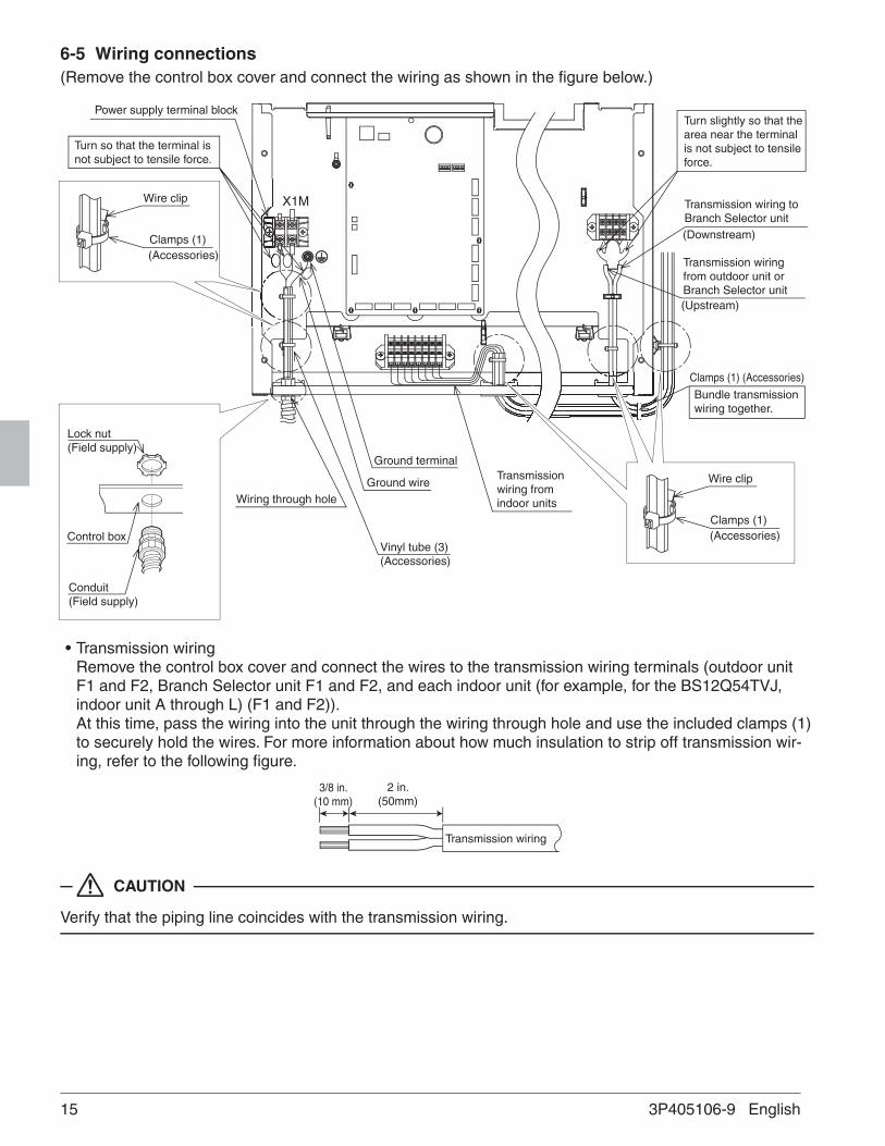
6-5 Wiring connections(Remove the control box cover and connect the wiring as shown in the figure below.)
X1M
Wire clip
Clamps (1)(Accessories)
Ground terminal
Ground wire
Vinyl tube (3)(Accessories)
Transmission wiring from indoor unitsWiring through hole
• Transmission wiring Remove the control box cover and connect the wires to the transmission wiring terminals (outdoor unit F1 and F2, Branch Selector unit F1 and F2, and each indoor unit (for example, for the BS12Q54TVJ, indoor unit A through L) (F1 and F2)). At this time, pass the wiring into the unit through the wiring through hole and use the included clamps (1) to securely hold the wires. For more information about how much insulation to strip off transmission wir-ing, refer to the following figure.
Transmission wiring
3/8 in. (10 mm)
2 in. (50mm)
CAUTION
Verify that the piping line coincides with the transmission wiring.
Turn slightly so that the area near the terminal is not subject to tensile force.
Transmission wiring to Branch Selector unit(Downstream)
Transmission wiring from outdoor unit or Branch Selector unit(Upstream)
Clamps (1) (Accessories)
Bundle transmission wiring together.
Conduit(Field supply)
Control box
Lock nut(Field supply)
Power supply terminal block
Turn so that the terminal is not subject to tensile force.
Wire clip
Clamps (1)(Accessories)
15 3P405106-9 English
01_EN_3P405106-9.indb 15 3/27/2015 1:53:12 PM

• Power supply wiring and ground wires Remove the control box cover and connect the power supply wiring to the power terminal block (X1M). Also connect the ground wire to the ground wire terminal. Pass both the power supply wires and the ground wire together through the wire through hole (left) into the control box and use the included clamps (1) to securely hold the wires in place. Be sure to wire the ground wire so that it comes out of the cut out slit in the cup washer. (Not doing so could cause insufficient ground wire contact, causing the wire not to function as a ground.) For more information about how much insulation to strip off power wiring, refer to the following figure.
L1
L2 Power wiring (3-core)
5 in. (130 mm)
Cut out slit
Cup washerRing type crimp style terminal
WARNING
Organize the wiring and securely reattach the control box cover. Pinched wires or a loose control box cover could result in electric shock or fire.
CAUTION
• When fastening the wire, use the included clamp (1) so as not to apply tensile force to the wire connec-tion and then securely fasten the wire. Also, after the wiring is completed, organize the wiring so that the control box cover does not pop up and then properly replace the control box cover. Make sure no wires are pinched when replacing the control box cover. Always use the wire through hole to protect wires.
• Do not pass the transmission wiring and power supply wiring through the same locations, and outside of the unit keep them sep-arated by at least 2 in. (50 mm). Not doing so could cause the transmission wiring to pick up electric noise (external noise) and result in a malfunction or breakdown.
• After the wiring work is complete, use sealer (to be supplied in the field) to seal closed the wire through hole. (Entry by small animals, etc., could cause a malfunction.)
• As shown in the figure to the right, wrap the transmission wiring between each Branch Selector unit and indoor unit with finishing tape (to be supplied in the field).
Gas pipe
Transmission wiring
Liquid pipe
Finishing tapeInsulation material
163P405106-9 English
01_EN_3P405106-9.indb 16 3/27/2015 1:53:12 PM

7. INITIAL SETTING
7-1 Settings in the fieldFollow the instructions below to set the DIP switches as necessary.
WARNING
Electric shock hazard! Before performing work, be sure to disconnect any power source con-nected to the unit.
Procedure
1. Disconnect the power source. 2. Set the DIP switches (DS1, DS2) for the corresponding branch ports based on the following table.3. Once work is complete, be sure to close the control box cover.
ONOFF
ONOFF
1A1P A3P
2 3 41 2
DS1DS2
3 4
A B C D I J K L
..................
..........
.......... ..........A B C D I J K LPiping branch port number
Terminal No. to which to connect transmission wiring
DIP switch
<Setting>
1. Setting for branch ports to which no indoor unit is connected
SettingSetting for branch ports to which no indoor unit is connected
(Example 1)(Example 1)When not connecting the indoor unit to the A and B branch circuits
ON
OFF 1 2
DS1 (A1P)
3 4
DIP switch settingON (Not connected)
OFF (Factory default)
DIP switch No.DS1
(A1P)DS1
(A2P)DS1
(A3P)1 2 3 4 1 2 3 4 1 2 3 4
BS4Q54TVJ
Target branch port
Uni
t A
Uni
t B
Uni
t C
Uni
t D
BS6Q54TVJ
Uni
t E
Uni
t F
BS8Q54TVJ
Uni
t G
Uni
t H
BS10Q54TVJ
Uni
t I
Uni
t JBS12Q54TVJ
Uni
t K
Uni
t L
17 3P405106-9 English
01_EN_3P405106-9.indb 17 3/27/2015 1:53:13 PM

2. Setting when joining branch ports
SettingSetting when joining branch ports
(Example 2)
(Example 2)When joining the A and B branches
ON
OFF 1 2
DS2 (A1P)
3 4
DIP switch settingON (Joined)
OFF (Factory default)
DIP switch No.DS2
(A1P)DS2
(A2P)DS2
(A3P)1 2 1 2 1 2
BS4Q54TVJ
Target branch port
A a
nd B
uni
ts jo
ined
C a
nd D
uni
ts jo
ined
BS6Q54TVJ
E a
nd F
uni
ts jo
ined
BS8Q54TVJ
G a
nd H
uni
ts jo
ined
BS10Q54TVJ
I and
J u
nits
join
ed
BS12Q54TVJ
K a
nd L
uni
ts jo
ined
When joining branches, only the branch port combinations shown in the above table can be used.(For example, units B and C cannot be joined.)
8. ADDING AN ADDITIONAL CHARGE OF REFRIGERANTFollow the instructions in the installation manual that came with the outdoor unit to add an additional charge of refrigerant.
9. CHECK OPERATION AND TEST OPERATION
1. Verify that the control box cover is closed.2. Refer to the installation manual included with the outdoor unit and conduct a check and a test run
after all the work on the Branch Selector unit and outdoor and indoor units is completed and the oper-ational safety of the units is confirmed.• You will hear the motor operated valve operating for about 90 seconds as it is automatically initial-
ized (closed) after power is turned on, but this is not a problem. • System malfunctions can be verified by means of the following methods:
Indication on the indoor operation remote controller Overall system malfunctions, including of the Branch Selector unit, can be identified using the LCD malfunction display on the operation remote controller. For more information about the malfunction display and its significance, refer to the service precaution name plate affixed to the indoor unit and the user manual included with the outdoor unit.
183P405106-9 English
01_EN_3P405106-9.indb 18 3/27/2015 1:53:13 PM

5151 San Felipe, Suite 500Houston, TX 77056
3P405106-9 EM14A003A [1506] HT
00_CV_3P405106-9.indd 2 4/20/2015 3:08:14 PM