installation manual - gray metal south inc
TRANSCRIPT

Installation Manual
I
I
I
I
I I
L
FOR USE IN RESIDENTIAL AND BUILDING HEATING APPLIANCES FUELED WITH GAS, LIQUID FUEL OR SOLID FUELS SUCH AS WOOD STOVES, COAL
STOVES, WATER HEATERS, GAS FURNACES AND OIL BURNERS
5” -6” - 7” - 8” DIAMETER
This Product is Listed by UNDERWRITERS LABORATORIES INC.
and Beam the Mark:
0 1992 GRA

INSTALLATION INSTRUCTIONS MAINTENANCE RECOMMENDATIONS
Thank you for purchasing Gray Stainless Flue Chimney liner. This high quality pro- duct will give you many years of fine service provided these installation instructions are followed and ypur Gray Stainless Flue chimney liner is maintained according to the sugguested schedule. Safe installation and operation of your heating system is imperative.
1 CHIMNEY PLACEMENT The National Fire protection association (NFPA) standard 211 requires that the chimney extend at least three feet above the highest point where it passes through the roof and must be at least two feet higher than any portion of the building located within ten feet of the chimney. (FIG. 1)
FP.,
j
i ~
When installing Gray Stainless Flue Chimney Liner in your masonry chimney do not allow the liner to ex- tend more than 12” above the termina- tion of the masonry chimney in order to
i I
~
CHIMNEY INSPECTION Prior to instaliation of your Gray Stainless Flue chimney liner the masonry chimney should be inspected for structural integrity. It must 6e stressed that the Gray Stainless Flue chimney liner is not a chimney structure itself. It is designed to line or reline existing structurally sound masonry chimneys. Inspect the chimney for loose or eroded mortar, cracked and or missing bricks. In the interior check for obstructions, unused flues and creosote build up. In this regard it is especially im- portant to remove tar glaze creosote deposits adhearing to the inside of the chimney. Al l exterior cracks must be filled, loose mortar and missing bricks replac- ed. Interior obstructions which may inhibit correct installation of the chimney lining system must be removed.
BUILDING CODES These instructions are to serve as a guide for qualified installation technicians. There may however be building codes in your area which reference this type of in-
i
, I
~~ __

stallation. Contact local building or fire officials about restrictions and installation inspection in your area. Do not substitute materials in your installation. Use only Gray Stainless Flue materials and Ther M ~ ~ T M insulation.
A. MAXIMUM AND MINIMUM LENGTH The minimum length of your Gray Stainless Flue Chimney liner shall be no less than fifteen(15)feet.The maximum lengthshall be nogreaterthan eighty(80)feet.
SIZE Gray Stainless Flue Chimney Liner must be sized to conform to your heating ap- pliance.Thediameterofthelinermust be noless thanthediameterofthefluecollar on the appliance or as otherwise specified by the appliance manufacturer.
In addition to the flue collar dimen- sions, chimney internal size must be considered. A minimum of one inch space is required between Gray Stainless Flue Chimney liner and the inside wall of the masonry chimney. For example a chimney measuring IO”x10” square may be lined with a maximum 8” round liner to allow 1” space around all surfaces. (FIG. 3)
Should the inside dimensions not be square, refer to the small dimension for proper size. As an example, a IO”x8” masonry chimney will permit a maximum 6 ’ diameter liner to insure a 1” wall space from the 8” dimension. To determine proper length of your Gray Stainless Flue liner assembly lower a weighted rope through the masonry chimney to its base. Remove the rope and measure the length. To determine the number of pipe lengths required for installa- tion subtract from liner assembly length the number of tees required. One tee will be required for appliance installation. One tee is recommended at the base of the in- stallation to serve as a clean out. When selecting the number of pipe lengths re- quired remember tosubtract 2” from each pipe length to determine the assembled length. For example a 36” pipe will yield 34“ assembled length. A 24” pipe will yield a 22” assembled length. Total tees plus pipe lengths equal assembly length.
CLEARANCE FOR COMBUSTABLE MATERIALS The maximum air space clearance between interior masonry chimneys and com- bustable materials shall be at least two (2) inches in conformance with the National
FiG 3
’
,
Fire Protection Association Standards #211. The minimum air space clearance between exterior masonry chimneys and com- bustable materials shall be one (1) inch in conformance with the National Fire Pro-
The air space in either instance shall not be filled. The minimum thickness of brick used in the construction of masonry chimneys to be lined with Gray Btainless Flue Chimney liner shall be four (4) inches in confor- mance with the National Fire Protection Association Standards #211.
INSTALLATION AND ASSEMBLY:
. tection Association Standards #211.
TOOLS AND MATERIALS Gloves Screwdriver Hammer Cold Chisel 118 high speed drill bit, masonry Ladder
Tin snips drill bit and electric drill I

Pop rivet gun Rope (sufficient to extend from
top to bottom of chimney Mortar mix and pan
MEASUREMENT
Trowel Silicon caulk Eye protector Steel S hook
Prior to installation locate the inlet to the chimney for your heating appliance. This location will determine placement of the tee through which your appliance will con- nect to the liner. Additionally, a tee should be located at the base of the liner assembly to serve as a cleanout.
CHIMNEY PREPARATION If an appliance is not presently con- nected to the chimney, an opening must be made in the brick. Locate a single brick at the midpoint of the area to be opened. Drill around the perimeter of the brick with a masonry drill bit. Remove surrounding bricks un- til the opening is large enough to insert the removable branch of the tee. Do not
FlG 1
remove an excessive amount of brick. (FIG. 4)
Repeat this process at the base of the chimney for the cleanout tee. Check the chimney to insure it is clean and free of excessive portrusions
Working from the roof with appropriate scaffolding lower the assembled tee body and liner pipe into the chimney using the rope and S hook to within 6” of the end of the first section of liner pipe. Secure the liner and assemble the next liner section with supplied rivets. Repeat the process insuring that the tee body which is to accept your appliance connector is located at the proper position behind the prepared opening in the chimney. Con- tinue the installation with liner pipe un- til 6” of pipe protrudes from the top of the chimney. (FIG. 6)
INSTALLATION: First assemble the bottom clean out tee body to a length of pipe liner. Remove the tee branch. The tee body is assembled by locating the 118” holes in the tee and drilling through the hole with a 1/8’ high speed drill. Pop rivet the sections with the rivets supplied. Insert a tee cap on the bottom of the tee. Do not rivet the cap to the tee as you may wish to remove it when clean- ing your liner. (FIG. 5)
FIG 6
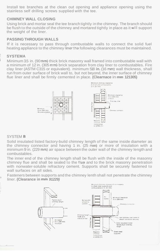
Install tee branches at the clean out opening and appliance opening using the stainless self drilling screws supplied with the tee.
CHIMNEY WALL CLOSING Using brick and mortar seal the tee branch tightly in the chimney. The branch should be flush to the outside of the chimney and mortared tightly in place as it will support the weight of the liner.
PASSING THROUGH WALLS If it is necessary to pass through combustable walls to connect the solid fuel heating appliance to the chimney linerthe following clearances must be maintained.
1 SYSTEMA i Minimum 3.5 in. (90 mm) thick brick masonry wall framed into combustable wall with
a minimum of 12 in. (305 mm) brick separation from clay liner to combustables. Fire clay liner (ASTM C315 or equivalent). minimum 518 in. (16 mm) wall thickness, shall run from outer surface of brick wall to, but not beyond, the inner surface of chimney flue liner and shall be firmly cemented in place. (Clearnace in mm 121305)
U,",mY. *,",.*" rlvnnrr IObtL.*-*I.II.
SYSTEM B Solid insulated listed factory-build chimney length of the same inside diameter as the chimney connector and having 1 in. (25 mm) or more of insulation with a minimum 9 in. (229 mm) air space between the outer wall of the chimney length and combustables. The inner end of the chimney length shall be flush with the inside of the masonry chimney flue and shall be sealed to the flue and to the brick masonry penetration with nonwater-soluble refractory cement. Supports shall be securely fastened to wall surfaces on all sides. Fasteners between supports and the chimney lenth shall not penetrate the chimney liner. (Clearance in mm 91229)
,
1
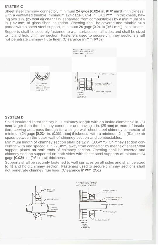
SYSTEM c Sheet steel chimney connector, minimum 24,'gage [0.024 in. (0.61mm)l in thickness, with a ventilated thimble, minimum 124 gage [0.024 in. (0.61 mm)] in thickness, hav- ing two 1 in. (25 mm) air channels, separated from combustables by a minimum of 6 in. (152 mm) of glass fiber insulation. Opening shall be covered and thimble sup ported with a sheet steel support, minimum 24 gage [0.24 in (0.61 mm)] in thickness. Supports shall be securely fastened to wall surfaces on all sides and shall be sized to fit and hold chimney section. Fasteners used to secure chimney sections shall not penetrate chimney flute liner. (Clearance in mm 61152)
SYSTEM D Solid insulated listed factory-built chimney length with an inside diameter 2 in. (51 mm) larger than the chimney connector and having 1 in. (25 ")or more of insula- tion, serving as a pass-through for a single wall sheet steel chimney connector of minimum 24 gage [0.024 in. (0.061 mm)] thickness, with a minimum 2 in. (51 mm) air space between the outer wall of chimney section and combustables. Minimum length of chimney section shall be 12 in. (305 mm). Chimney section con- centric with and spaced 1 in. (25 mm) away from connector by means of sheet steel support plates on both ends of chimney section. Opening shall be covered and chimney section supported on both sides with sheet steel supports of minimum 24 gage [0.024 in. (0.61 mm)] thickness. Supports shall be securely fastened to wall surfaces on all sides and shall be sized to fit and hold chimney section. Fasteners used to secure chimney sections shall not penetrate chimney flue liner. (Clearance in mm 2/51)

- ADDITIONAL REQUIREMENTS:
1. Insulation material used as part of wall pass-through system shall be of non- combustable material and shall have a thermal conductivity of 1.0 Btu*in.lft2* "F (4.88kg-cal/hr*m2* "C) or less.
2. Al l clearances and thicknesses are minimums; larger clearances and thicknesses are acceptable.
3. Any material used to close up an opening for the connector shall be of noncom- bustable material.
4. A connector to a masonry chimney, except for System B, shall extend to on piece through the wail pass-through system and the chimney wall to the inner face of the flue liner, but not beyond.
Do not connect more than one solid fuel appliance to a single chimney liner.
Do not connect gas fired appliances to liners connected to solid fuel appliances.
INSULATION: Before securing the chimney top pour proper insulation around the liner. Gray Stainless Flue Chimney Liner must be insulated with Ther MixTM listed insulation. Insulation not only makes your Gray Stainless Flue Chimney liner a safe system; it additionally reduces condensation and creosote and increases the rigidity of the en- tire chimney. Listed Ther MixTM insulation should be installed in conformance with manufacturers instructions. Following said instructions, insure the liner is centered in the chimney and fill to within 6" of the chimney top. After installation of your Gray Stainless Flue Chimney liner and your heating ap- pliance is complete, the following precautions must be taken.
A. If time permits, a period of three weeks should elapse prior to fir- ing the appliance in order to allow the Ther MixTM insulation to cure and expel excess moisture.
B. Curing may be accelerated by fir- ing the appliance to attain a temperature of 500" at the chimney liner for a period of 24 hours.
FINISHING THE INSTALLATION Install a cover plate on top of the chimney, cutting the plate to fit over the top of the chimney and seal with silicon caulk. Do not seal the liner to the top plate. The top plate serves as a chimney cover and location for the liner, but the liner must be allowed to expand ver- tically during heating and cooling. (FIG. 7)

7 - MAINTENANCE Your Gray Stainless Flue Chimney Liner should be cleaned at least once a year by a professionally certified Chimney Sweep. The chimney liner system should be inspected monthly during the heating season to determine i f creosote or soot build up has occured. If creosote or soot has accumulated, it should be removed to reduce the risk of a chimney fire.
CREOSOTE AND SOOT FORMATION AND NEED FOR REMOVAL When wood is burned slowly, it produces tar and other organic vapors, which com- bine with expelled moisture to form creosote. The creosote vapors may condense on the inside of the chimney liner during slow-burning firing periods. As a result, creosote residue accumulates on the chimney liner. When ignited, this creosote makes an extremely hot fire.
TO CLEAN YOUR GRAY STAINLESS FLUE CHIMNEY LINER
1
A. The chimney cap must be removable. Do not rivet the chimney cap to the liner.
B. Remove the chimney cap from the top of the installation when the liner is cool. C. Using a chimney cleaning brush of the proper diameter for the liner brush in an
up and down motion throughout the length of the lining assembly. AC- cumulated creosote deposits will drop to the bottom of the assembly.
, I Use the stainless steel screws supplied with the chimney cap.
I : D. Remove accumulated creosote deposits from the base of the clean out tee.