installation manual by-3500t - trade electric gates uk the automated gate is not an entrapment...
TRANSCRIPT

OPERATOR FOR SLIDING GATES119BW41EN
Installation manual
BY-3500T
English EN

BY 3500T
Pag
e 2
-
Man
ual
cod
e: 1
19
BW
41
EN
119
BW
41
EN
ver
s. 4
0
4/2
014
©
CA
ME
cance
lli a
utom
atic
i s.p
.a.
- Th
e dat
a an
d in
form
atio
n pro
vided
in t
his
man
ual
are
subje
ct t
o ch
ange
at a
ny t
ime
with
out
prio
r not
ice
by C
AM
E C
ance
lli A
utom
atic
i S.p
.a.
Foreword
• This product should only be used for the purpose for which it was explicitly designed. Any other use is considered dangerous. CAME Cancelli Automatici S.p.A. is not liable for any damage resulting from improper, wrongful or un-reasonable use • Keep these warnings with the installation and use manuals issued with the automation system.
Before installing
(preliminary check: in case of a negative outcome, do not proceed until you have complied with the safety requirements)• Check that the part you intend to automate is in good mechanical condition, balanced and aligned, and that it opens and closes properly. Make sure that proper mechanical stops are already in place • If the operator will be installed at a height of less than 2.5 m from the ground or other access level, check whether you will need any protections and/or warnings • Any gate leaves fi tted with pedestrian entrances onto which you will install an operator must have a blocking mechanism when the gate is in motion • Make sure that the opening of the automated gate is not an entrapment hazard as regards any surrounding fi xed parts • Do not mount the operator upside down or onto any elements that may fold under its weight. If needed, add suitable reinforcements at the points where it is secured • Do not install onto gates not on level ground • Check that any lawn watering devices will not wet the operator from the bottom up.
Installation
• Carefully section off the entire site to prevent unauthorised access, espe-cially by minors and children • Be careful when handling operators that weigh more than 20 kg. In such cases, use proper weight handling safety equipment • All opening commands (e.g. buttons, key selector switches, magnetic detec-tors etc.) must be installed at least 1.85 m from the gate’s area of operation perimeter - or where they cannot be reached from the outside of the gate. Also, the direct commands (buttons, touch commands etc.) must be installed at a height of at least 1.5 m and must not be accessible to the public • All ‘hold-to-run’ commands must be placed where the moving gate leaves, transit areas and driveways are completely visible • If missing, apply a permanent label that shows the position of the release mechanism • Before delivering to the user, check that the system is EN 12453 (impact test) standard compliant. Make sure that the operator has been properly adjusted and that the safety and protection devices as well as the manual release are working properly • Where necessary and in plain sight, apply the Warning Signs (e.g. gate plate)
Special instructions and advice for users
• Keep the gate’s area of operation clean and clear of any obstacles. Check that there is no vegetation in the area of operation of the photocells and that there are no obstacles in the area of operation of the operator • Do not allow children to play with the fi xed command devices, or in the gate’s area of ope-ration. Keep any remote control devices (i.e. transmitters) or any control devi-ces away from children as well, to prevent the operator from being activated accidentally •The operator is not designed to be used by persons (including children) whose physical, sensorial or mental capacities are limited, or who are lacking in experience or knowledge, unless said persons can be supervised or given instructions regarding using the operator by a person responsible for their safety • Frequently check the system, to see whether any anomalies or signs of wear and tear appear on the moving parts, on the component parts, on the securing points, on the cables and any accessible connections. Keep any joints (i.e. hinges) lubricated and clean, and do the same where friction may occur (i.e. slide rails) • Perform functional tests on photocells and sensitive edges every six months. To check that the photocells work, pass an object in front of them during closing. If the operator reverses the direction of movement or comes to a halt, the photocells work correctly. This is the only maintenan-ce operation that must be carried out while the operator is live. Ensure that the glass on the photocells is kept clean (use a cloth slightly moistened with water; do not use solvents or any other chemicals as these could damage the devices) • If the system requires repairs or modifi cations, release the opera-tor and do not use it until safety conditions have been restored • Cut off the power supply before releasing the operator for manual openings and before any other operation, to prevent dangerous situations. Read the instructions • If the power cable is damaged, it must be replaced by the manufacturer or
the technical assistance service or by a person with a similar qualifi cation so as to prevent any risks • It is STRICTLY FORBIDDEN for users to perform OPERATIONS THEY ARE NOT EXPLICITLY REQUIRED AND ASKED to do in the manuals. For repairs, adjustments and extraordinary maintenance, CONTACT THE SPECIALIST TECHNICAL SERVICE CENTRE • On the periodic maintenance log, note down the checks you have done.
Special instructions and advice for all
• Avoid working near the hinges or moving mechanical parts • Stay clear of the gate’s area of operation when in motion • Do not resist the direction of movement of the gate; this may present a safety hazard • At all times be extremely careful about dangerous points that must be indicated by proper pictograms and/or black and yellow stripes • When using a selector or com-mand in ‘hold-to-run’ mode, keep checking that there are no people in the area of operation of the moving parts. Do this until you release the command • The gate may move at any time without warning • Always cut the power when cleaning or performing maintenance.
Danger of hand crushing
Danger - live parts
No transit during the manoeuvre
CAUTION!important personal safety instructions:
READ CAREFULLY!

2
6
10
1
BY 3500T
7
9 11
3 4
5
8
12
Pag
e 3
-
Man
ual
cod
e: 1
19
BW
41
EN
119
BW
41
EN
ver
s. 4
0
4/2
014
©
CA
ME
cance
lli a
utom
atic
i s.p
.a.
- Th
e dat
a an
d in
form
atio
n pro
vided
in t
his
man
ual
are
subje
ct t
o ch
ange
at a
ny t
ime
with
out
prio
r not
ice
by C
AM
E C
ance
lli A
utom
atic
i S.p
.a.
KEY
This symbol indicates parts to read carefully.
⚠ This symbol indicates parts about safety.
☞ This symbol tells you what to say to the end users.
DESCRIPTION
This product has been designed and built by CAME CANCELLI AUTOMATICI S.p.A. in compliance with applicable safety standards.
The operator consists of a cast aluminium part, with a non-reversible electromechanical gearmotor operating inside and an ABS container for the control board with
the transformer.
Intended use
The BY-3500T operator has been designed to power sliding gates for industrial use.
Any installation and operation that differs from what is set out in this manual is prohibited.
Limits of use
Type BY-3500T
Max. leaf length (m) 23
Max. leaf weight (kg) 3.500
REGULATORY REFERENCES
Came Cancelli Automatici is a company with an ISO 9001-certified company quality management system and an ISO 14001-certified environmental management
system.
The product in question complies with the regulations referred to in the declaration of conformity.
Technical data
Type BY-3500T
Protection rating (IP) 54
Power supply (V - 50/60 Hz) 230/400 AC THREE-PHASE
Motor power supply (V - 50/60 Hz) 230/400 AC THREE-PHASE
Current draw (A) 2
Power (W) 750
Thrust (N) 3500
Opening speed (m/min) 10,5
Duty cycle (%) 50
Operating temperature (°C) -20 - +55
Motor thermal protection (°C) 150
Gear ratio (i) 1/28
Insulation class
Weight (kg) 74
Packing list
1. 1 x operator
2. 1 x fixing plate
3. 1 x installation manual
4. 2 x UNI5588 M12 nuts
5. 2 x washers
6. 2 x UNI5739 M12x70 screws
7. 4 x UNI5927 M6x25 end run grub screws
8. 2 x keys for inspection hatch
9. 2 x anchor brackets
10. 1 x left-hand end run fin
11. 1 x right-hand end run fin
12. 1 x release key

5
7
3
BY 3500T
8
6
9
2
4
10
1
11
==
578
171
167
222
480275295
Pag
e 4
-
Man
ual
cod
e: 1
19
BW
41
EN
119
BW
41
EN
ver
s. 4
0
4/2
014
©
CA
ME
cance
lli a
utom
atic
i s.p
.a.
- Th
e dat
a an
d in
form
atio
n pro
vided
in t
his
man
ual
are
subje
ct t
o ch
ange
at a
ny t
ime
with
out
prio
r not
ice
by C
AM
E C
ance
lli A
utom
atic
i S.p
.a.
Dimensions (mm)
GENERAL INSTALLATION INSTRUCTIONS
⚠ Installation must be carried out by qualified and experienced personnel in compliance with applicable regulations.
Preliminary checks
⚠ Before installing the operator:
• Check that the gate is stable, and that the sliding wheels are in good condition and greased.
• Check that the ground guide is securely fixed to the ground, completely on the surface and free from irregularities that may hinder gate movement.
• Check that the upper guide blocks do not create friction.
• Make sure there is one opening and one closing mechanical stop.
• Make sure that the mounting point for the gearmotor is in an area protected from impacts and that the anchoring surface is solid;
• Provide a suitable single-pole disconnection device, with a maximum of 3 mm between the contacts, to disconnect the power supply;
• Make sure that any connections within the container (made to ensure the continuity of the protection circuit) are fitted with extra insulation compared to the
other internal conductor parts;
• Prepare suitable piping and ducts for routing the electrical cables, ensuring protection against mechanical damage.
Description of the components
1. Cabinet
2. Gearmotor
3. Control panel
4. Inspection panel
5. Fixing plate
6. Nut
7. Washer
8. Anchor bracket
9. Screw
10. Release nut
11. Customised DIN keys
1
2
2
3
4
5 6
7
7 8
8
9
11
10
Pag
e 5
-
Man
ual
cod
e: 1
19
BW
41
EN
119
BW
41
EN
ver
s. 4
0
4/2
014
©
CA
ME
cance
lli a
utom
atic
i s.p
.a.
- Th
e dat
a an
d in
form
atio
n pro
vided
in t
his
man
ual
are
subje
ct t
o ch
ange
at a
ny t
ime
with
out
prio
r not
ice
by C
AM
E C
ance
lli A
utom
atic
i S.p
.a.
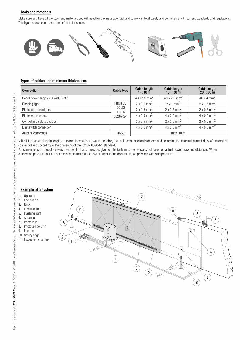
Types of cables and minimum thicknesses
Connection Cable type Cable length1 < 10 m
Cable length10 < 20 m
Cable length20 < 30 m
Board power supply 230/400 V 3P
FROR CEI
20-22
IEC EN
50267-2-1
4G x 1.5 mm2 4G x 2.5 mm2 4G x 4 mm2
Flashing light 2 x 0.5 mm2 2 x 1 mm2 2 x 1.5 mm2
Photocell transmitters 2 x 0.5 mm2 2 x 0.5 mm2 2 x 0.5 mm2
Photocell receivers 4 x 0.5 mm2 4 x 0.5 mm2 4 x 0.5 mm2
Control and safety devices 2 x 0.5 mm2 2 x 0.5 mm2 2 x 0.5 mm2
Limit switch connection 4 x 0.5 mm2 4 x 0.5 mm2 4 x 0.5 mm2
Antenna connection RG58 max. 10 m
N.B.: If the cables differ in length compared to what is shown in the table, the cable cross-section is determined according to the actual current draw of the devices
connected and according to the provisions of the IEC EN 60204-1 standard.
For connections that require several, sequential loads, the sizes given on the table must be re-evaluated based on actual power draw and distances. When
connecting products that are not specified in this manual, please refer to the documentation provided with said products.
Tools and materials
Make sure you have all the tools and materials you will need for the installation at hand to work in total safety and compliance with current standards and regulations.
The figure shows some examples of installer’s tools.
Example of a system
1. Operator
2. End run fin
3. Rack
4. Key selector
5. Flashing light
6. Antenna
7. Photocells
8. Photocell column
9. End run
10. Safety edge
11. Inspection chamber

400
600
400
50
142
220
Pag
e 6
-
Man
ual
cod
e: 1
19
BW
41
EN
119
BW
41
EN
ver
s. 4
0
4/2
014
©
CA
ME
cance
lli a
utom
atic
i s.p
.a.
- Th
e dat
a an
d in
form
atio
n pro
vided
in t
his
man
ual
are
subje
ct t
o ch
ange
at a
ny t
ime
with
out
prio
r not
ice
by C
AM
E C
ance
lli A
utom
atic
i S.p
.a.
INSTALLATION
⚠ The following illustrations are only examples, given that the space for securing the operator and accessories varies depending on the overall dimensions. The
installation technician is responsible for choosing the most suitable solution.
Installing corrugated tubes
Drill the hole for the counterframe.
Prepare the junction boxes and corrugated tubes necessary for the connections from the inspection chamber. In order to
connect the gearmotor, a Ø 60 mm corrugated tube is advisable. Ø 25 mm pipes are recommended for accessories, on
the other hand.
N.B. the number of tubes depends on the type of system installed and any accessories.
Installing the mounting plate
Prepare a counterframe that is larger than the mounting plate and place it in the hole. The counterframe must protrude 50 mm from ground level.
Insert an iron grid inside the counterframe to reinforce the concrete.
Secure the anchor brackets to the plate using the screws, nuts and washers supplied.
Position the mounting plate, respecting the measurements shown on the drawing, if the rack is already present.
Caution! The tube must pass through the prepared hole.

24h
3
BY 3500T
BY 3500T
2
2
1
BY 3500T
1
Pag
e 7
-
Man
ual
cod
e: 1
19
BW
41
EN
119
BW
41
EN
ver
s. 4
0
4/2
014
©
CA
ME
cance
lli a
utom
atic
i s.p
.a.
- Th
e dat
a an
d in
form
atio
n pro
vided
in t
his
man
ual
are
subje
ct t
o ch
ange
at a
ny t
ime
with
out
prio
r not
ice
by C
AM
E C
ance
lli A
utom
atic
i S.p
.a.
Fill the counterframe with cement. The plate must be perfectly level with the screw threads completely on the surface.
Allow to cure for at least.
Remove the counterframe and fill the hole around the block of cement with earth.
Remove the nuts and washers from the screws.
Insert the electric cables in the tube until they protrude by approximately 600 mm.
Securing the gearmotor
Remove the inspection hatch using the customised key. Unscrew the side screws and lift the cabinet out of the gearmotor.

BY 3500T
BY 3500T
BY 3500T
+
---
++++++++
TBY 3500T0T
-
+
-
BY 3500T
BY 3500T
Pag
e 8
-
Man
ual
cod
e: 1
19
BW
41
EN
119
BW
41
EN
ver
s. 4
0
4/2
014
©
CA
ME
cance
lli a
utom
atic
i s.p
.a.
- Th
e dat
a an
d in
form
atio
n pro
vided
in t
his
man
ual
are
subje
ct t
o ch
ange
at a
ny t
ime
with
out
prio
r not
ice
by C
AM
E C
ance
lli A
utom
atic
i S.p
.a.
Unlock the gearmotor. Rest the rack on top of the gearmotor pinion.
Position the gearmotor above the mounting plate. Caution! The electrical cables must pass under the gearmotor box.
Lift the gearmotor 5 to 10 mm up from the plate, using the threaded steel feet for any subsequent adjustments between the pinion and the rack.
Weld or secure the rack to the gate along its entire length.
Assemble the rack modules by using a piece of scrap placed under the join point, securing it using two terminals.
N.B. if the rack is already present, proceed directly with adjusting the pinion/rack coupling distance.

+
-BY 3500T
+
-
BY 3500T
+
-
BY 3500T
BY 3500T
Pag
e 9
-
Man
ual
cod
e: 1
19
BW
41
EN
119
BW
41
EN
ver
s. 4
0
4/2
014
©
CA
ME
cance
lli a
utom
atic
i s.p
.a.
- Th
e dat
a an
d in
form
atio
n pro
vided
in t
his
man
ual
are
subje
ct t
o ch
ange
at a
ny t
ime
with
out
prio
r not
ice
by C
AM
E C
ance
lli A
utom
atic
i S.p
.a.
Open and close the gate manually and adjust the pinion/rack coupling distance using the threaded feet (vertical adjustment) and the slots (horizontal adjustment).
This prevents the weight of the gate bearing upon the operator.
When adjustment is complete, secure the gearmotor to the plate using the washers and nuts.
Vertical adjustment
Horizontal adjustment

1
7
12
5
8
10
112369
4
Pag
e 1
01
0
- M
anual
cod
e: 1
19
BW
41
EN
119
BW
41
EN
ver
s. 4
0
4/2
014
©
CA
ME
cance
lli a
utom
atic
i s.p
.a.
- Th
e dat
a an
d in
form
atio
n pro
vided
in t
his
man
ual
are
subje
ct t
o ch
ange
at a
ny t
ime
with
out
prio
r not
ice
by C
AM
E C
ance
lli A
utom
atic
i S.p
.a.
Determining the end run points
Position the end run fins on the rack and secure them using the 3 mm hex key. Their position limits the gate run.
N.B. ensure that the gate does not strike against the mechanical stop during opening or closing.
Left-hand end run fi n
Right-hand end run fi n
ELECTRICAL CONNECTIONS
⚠ Caution! Before intervening on the control panel, disconnect mains power.
Control board power supply: 230/400 VAC three-phase, with frequency of 50-60 Hz.
Control device power supply: 24 VAC.
⚠ The total power of the accessories should not exceed 40 W.
The functions must be set using the dip switches and the adjustments using the trimmers.
All the connections are protected by quick fuses.
Description of the components
1. Dip switch2. Panel fuse3. Accessory fuse4. Line fuses5. Connector for AF card6. Power indicator LED7. Programming indicator LED8. Terminal block for control and
safety devices9. Transformer terminal block10. Radio code memorisation buttons11. ACT trimmer: adjusting the
automatic closing time12. PART.OP. trimmer: adjusting
partial opening
FUSE TABLE
Line fuses 8 A-F
Panel fuse 630 mA-F
Accessory fuse 2 A-F

R
T S
N
R
T S
N
BY 3500T
BY 3500T
M
M
Pag
e 1111
-
Man
ual
cod
e: 1
19
BW
41
EN
119
BW
41
EN
ver
s. 4
0
4/2
014
©
CA
ME
cance
lli a
utom
atic
i s.p
.a.
- Th
e dat
a an
d in
form
atio
n pro
vided
in t
his
man
ual
are
subje
ct t
o ch
ange
at a
ny t
ime
with
out
prio
r not
ice
by C
AM
E C
ance
lli A
utom
atic
i S.p
.a.
Power supply
The gearmotor is designed to be powered at 400 V three-phase.
With 230 V three-phase power supply.
Remove the control panel, the mounting bracket and the connection cover.
Changing the connections of the gearmotor contacts. Replace the control panel and, on the control board, move the short circuit bridge from the 400 V terminal to
the 230 V terminal.
Control panel power supply
230/400 V AC - three-
phase
Terminals for powering the
accessories at 24 VAC.
24 VAC output in movement.
Overall power permitted: 45 W
Connecting the gearmotor and end run
The motor is designed to be installed on the left, inside view.
If installing on the right, inside view, reverse the motor and end run terminals on the control panel.
END RUN
END RUN

Pag
e 1
21
2
- M
anual
cod
e: 1
19
BW
41
EN
119
BW
41
EN
ver
s. 4
0
4/2
014
©
CA
ME
cance
lli a
utom
atic
i s.p
.a.
- Th
e dat
a an
d in
form
atio
n pro
vided
in t
his
man
ual
are
subje
ct t
o ch
ange
at a
ny t
ime
with
out
prio
r not
ice
by C
AM
E C
ance
lli A
utom
atic
i S.p
.a.
Stop button (N.C. contact) Stops the gate with the exclusion of
automatic closing. To resume movement, press the control button
or other control device.
N.B. if not used, set dip switch 10 to ON.
OPEN ONLY function from the control device (N.O. contact)
OPEN-STOP-CLOSE-STOP (sequential) function / OPEN-CLOSE-
REVERSE (step-by-step) from the control device (N.O. contact)
See dip switch 2 and 3 function selection.
PARTIAL OPENING function from the control device (N.O. contact)
CLOSE ONLY function from the control device (N.O. contact)
Cycle/courtesy lamp (Contact capacity: 230 V - 60 W max.).
With dip switch 16 set to OFF and dip switch 17 set to ON = Cycle lamp.
Lights the area of operation. It remains on from the start of gate opening
to complete closing (including the automatic closing time).
With dip switch 16 set to ON and dip switch 17 set to OFF = Courtesy
lamp.
Lights the area of operation; stays on for a set time of 330 seconds
after an opening command.
Gate open indicator light (contact capacity:
24 V - 3 W max.)
Indicates that the gate is open.
Flashing light (Contact rated for:
230 V AC - 25 W max.).
Flashes during gate opening and
closing.
Gate closed indicator light (contact capacity:
24 V - 3 W max.)
Indicates that the gate is closed.
Control devices
Indicator and lighting devices

RX
RX
TX
TX
DELTA
DIR / DELTA S
Pag
e 1
31
3
- M
anual
cod
e: 1
19
BW
41
EN
119
BW
41
EN
ver
s. 4
0
4/2
014
©
CA
ME
cance
lli a
utom
atic
i s.p
.a.
- Th
e dat
a an
d in
form
atio
n pro
vided
in t
his
man
ual
are
subje
ct t
o ch
ange
at a
ny t
ime
with
out
prio
r not
ice
by C
AM
E C
ance
lli A
utom
atic
i S.p
.a.
C1 = Contact (N.C.) for reopening during closing.
Input for safety devices such as photocells, sensitive edges
and other devices compliant with the EN 12978 standard.
While the operator is closing, the opening of the contact
causes the reversal of the direction of movement until
completely open.
If C1 is not used, set dip switch 7 to ON.
CX with dip switch 8 and dip switch 9 OFF = Contact (N.C.)
for reclosing during opening.
Input for safety devices such as photocells, sensitive edges
and other devices compliant with the EN 12978 standard.
While the operator is opening, the closing of the contact
causes the reversal of the direction of movement until
completely closed.
CX with dip switch 8 OFF and dip switch 9 ON = Contact
(N.C.) for partial stop.
Input for safety devices such as photocells, sensitive edges
and other devices compliant with the EN 12978 standard.
Stops the operator, if it is moving, and then sets automatic
closing.
If CX is not used, set dip switch 8 to ON.
Safety devices
PhotocellsDIR / DELTA-S
PhotocellsDELTA
Photocell safety connection
With each opening or closing command, the panel checks that the photocells work. Any
anomaly inhibits any command.
Set dip switch 13 to ON.

+T.C.A- +AP.PARZ.-
Pag
e 14
14
-
Man
ual
cod
e: 1
19
BW
41
EN
119
BW
41
EN
ver
s. 4
0
4/2
014
©
CA
ME
cance
lli a
utom
atic
i s.p
.a.
- Th
e dat
a an
d in
form
atio
n pro
vided
in t
his
man
ual
are
subje
ct t
o ch
ange
at a
ny t
ime
with
out
prio
r not
ice
by C
AM
E C
ance
lli A
utom
atic
i S.p
.a.
1 ON - AUTOMATIC CLOSING function activated
2 ON - OPEN-STOP-CLOSE-STOP function from the transmitter and/or the button (2-7) activated
2 OFF - OPEN-CLOSE function from the transmitter and/or the button (2-7) activated
3 ON - OPEN ONLY function from the transmitter activated
4 ON - HOLD-TO-RUN function activated
5 ON - PRE-FLASHING during opening and closing activated
6 ON - OBSTACLE DETECTION function activated
7 OFF - REOPENING during closing (2-C1) function activated
8 OFF / 9 OFF - RECLOSING during opening (2-CX) function activated
8 OFF / 9 ON - PARTIAL STOP function (2-CX) activated; (if the devices are not connected on 2-CX, set dip switch 8 to ON)
10 OFF - TOTAL STOP function with button (1-2) activated
11 - Not used, keep the dip switch in the OFF position
12 ON - PARTIAL OPENING function activated; automatic closing occurs after a set time of 8 seconds.
12 OFF - PARTIAL OPENING function activated; automatic closing, if envisaged, occurs after a time that can be set at between 1 and 14 seconds
using the trimmers.
13 ON - Safety test function to check photocell efficiency activated; (13 OFF - disabled)
14 - Not used, keep the dip switch in the OFF position
15 - Not used, keep the dip switch in the OFF position
16 ON - COURTESY LAMP function activated
17 ON - CYCLE LAMP function activated
18 - Not used, keep the dip switch in the OFF position
19 - Not used, keep the dip switch in the OFF position
20 - Not used, keep the dip switch in the OFF position
ACT trimmer - Adjustment of the AUTOMATIC CLOSING time: from a minimum of 1 second to a maximum of 120 seconds.
PART.OP. trimmer - Adjustment of the PARTIAL OPENING time from a minimum of 1 second to a maximum of 14 seconds.
Selecting the functions
Adjustments

❶
❷
❸
❹ ❺
TOP TAM
Pag
e 1
51
5
- M
anual
cod
e: 1
19
BW
41
EN
119
BW
41
EN
ver
s. 4
0
4/2
014
©
CA
ME
cance
lli a
utom
atic
i s.p
.a.
- Th
e dat
a an
d in
form
atio
n pro
vided
in t
his
man
ual
are
subje
ct t
o ch
ange
at a
ny t
ime
with
out
prio
r not
ice
by C
AM
E C
ance
lli A
utom
atic
i S.p
.a.
Connect the antenna RG58 cable to the terminals and any accessory to connect to the B1-B2 output (N.O. contact) ❶.
For the AF43S / AF43SM radiofrequency cards only, position the jumper as shown according to the series of transmitters used ❷.
DISCONNECT POWER AND REMOVE THE BATTERIES, IF PRESENT. Insert the AF card on the control board.
N.B. the control board only recognises the AF card when the operator is powered again❸.
Hold down the CH1 key on the control board: the LED indicator flashes. Press a key on the transmitter to send the code. The LED will remain lit to indicate
SUCCESSFUL memorisation ❹.
Follow the same procedure with the CH2 key, associating it with another transmitter key ❺.
CH1 = channel for direct control of a panel function (OPEN ONLY, OPEN-CLOSE-REVERSE or OPEN-STOP-CLOSE-STOP, according to the selection made on dip
switches 2 and 3).
CH2 = channel for commands directed to an accessory device connected on B1-B2 or for connecting two coupled motors having a single command.
Contact rating: 5 A-24 V DC
Activating the radio control
Antenna
Control board
AF card
Indicator LED

BY 3500T
2
2
1
BY 3500T
31
BY 3500T
BY 3500TBY 3500T
1
BY 3500T
BY 3500T
Pag
e 1
61
6
- M
anual
cod
e: 1
19
BW
41
EN
119
BW
41
EN
ver
s. 4
0
4/2
014
©
CA
ME
cance
lli a
utom
atic
i s.p
.a.
- Th
e dat
a an
d in
form
atio
n pro
vided
in t
his
man
ual
are
subje
ct t
o ch
ange
at a
ny t
ime
with
out
prio
r not
ice
by C
AM
E C
ance
lli A
utom
atic
i S.p
.a.
FINAL OPERATIONS
Securing the cover
Releasing the gearmotor
RELEASING
⚠ The operation must be carried out while the power is off .
LOCKING
After making the electrical connections and selecting the functions and adjustments, fi t the cabinet on the gearmotor and secure it.

CAME
CAME
CAME
CAME
CAME
CAME
CAME
CAME
CAME
CAME
CAME
BY 3500T
BY 3500T
BY 3500T
BY 3500T
BY 3500T
Pag
e 1717
-
Man
ual
cod
e: 1
19
BW
41
EN
119
BW
41
EN
ver
s. 4
0
4/2
014
©
CA
ME
cance
lli a
utom
atic
i s.p
.a.
- Th
e dat
a an
d in
form
atio
n pro
vided
in t
his
man
ual
are
subje
ct t
o ch
ange
at a
ny t
ime
with
out
prio
r not
ice
by C
AM
E C
ance
lli A
utom
atic
i S.p
.a.
CONNECTING TWO COUPLED GEARMOTORS HAVING A SINGLE CONTROL
With two coupled gearmotors, you can command only the opening (by button and/or radio control): the gate will close only in automatic closing mode.
1 Coordinate the direction of travel of the two gearmotors A and B, by modifying the motor’s rotation B (invert the cables on terminals FA-FC and U-V).
2 Make the electrical connections only on the motor’s control board A. Whereas, the adjustments and features, must be made on both boards.
3 Connect the two boards together, as illustrated. Set DIP 1 and 3 to ON on both boards.
4 Fit the AF board only into the gearmotor’s board A. The transmitter button for opening a gate must be memorized on the gearmotor’s channel CH1 A. The transmitter button for opening both gates must
be memorized on the gearmotor’s channel CH2 A.

BY 3500T
Pag
e 1
81
8
- M
anual
cod
e: 1
19
BW
41
EN
119
BW
41
EN
ver
s. 4
0
4/2
014
©
CA
ME
cance
lli a
utom
atic
i s.p
.a.
- Th
e dat
a an
d in
form
atio
n pro
vided
in t
his
man
ual
are
subje
ct t
o ch
ange
at a
ny t
ime
with
out
prio
r not
ice
by C
AM
E C
ance
lli A
utom
atic
i S.p
.a.
Date Notes Signature
Periodic maintenance
Periodic maintenance log to be completed by the user (every six months)
MAINTENANCE
☞Before any maintenance, disconnect line voltage to prevent any possible dangerous situations that can be caused by accidental movement of the operator.
Lubricate the rotation points with grease whenever abnormal vibrations or squeaking occurs, as shown below.

Pag
e 1
91
9
- M
anual
cod
e: 1
19
BW
41
EN
119
BW
41
EN
ver
s. 4
0
4/2
014
©
CA
ME
cance
lli a
utom
atic
i s.p
.a.
- Th
e dat
a an
d in
form
atio
n pro
vided
in t
his
man
ual
are
subje
ct t
o ch
ange
at a
ny t
ime
with
out
prio
r not
ice
by C
AM
E C
ance
lli A
utom
atic
i S.p
.a.
Extraordinary maintenance log
Extraordinary maintenance
⚠The table below is used to note any extraordinary maintenance, repairs or improvements carried out by specialist companies.
⚠ Extraordinary maintenance must be carried out by specialist technicians.
DISMANTLING AND DISPOSAL
☞CAME CANCELLI AUTOMATICI S.p.A. implements an EN ISO 14001-certified and compliant Environmental Management System at its plants, to ensure
environmental protection.
Please continue our efforts to protect the environment, something that CAME considers to be one of the foundations in developing its business and market strategies,
simply by observing brief recommendations as regards disposal:
DISPOSAL OF PACKAGING
Packaging components (cardboard, plastic etc.) can be disposed of together with normal household waste without any difficulty, by simply separating the different
types of waste and recycling them.
Before proceeding, it is always advisable to check specific regulations in force in the place of installation.
DISPOSE OF PROPERLY!
DISPOSAL OF THE PRODUCT
Our products are made with different materials. Most of them (aluminium, plastic, iron, electrical cables) can be disposed of together with normal household waste.
They can be recycled if collected, sorted and sent to authorised centres.
Other components (Control boards, transmitter batteries etc.), on the other hand, may contain pollutants.
They should therefore be removed and handed over to companies authorised to recover and recycle them.
Before proceeding, it is always advisable to check specific regulations in force in the place of disposal.
DISPOSE OF PROPERLY!
TROUBLESHOOTING
MALFUNCTIONS POSSIBLE CAUSES CHECKS AND REMEDIES
The gate does not open or close • No power
• The gearmotor is unlocked
• The transmitter battery is flat
• The transmitter is broken
• The stop button is stuck or broken
• The opening/closing button or the key selector switch are stuck
• Photocell partial stop
• Check for mains power
• Lock the gearmotor
• Replace the batteries
• Contact service
• Contact service
• Contact service
• Contact service
The gate opens but does not close • The photocells are engaged
• Sensitive edge triggered
• Check that the photocells are clean and work
correctly
• Contact service
The gate closes but does not open • Sensitive edge triggered • Contact service
Installation technician stamp Operator name
Date of intervention
Technician signature
Customer signature
Intervention carried out ________________________________________________________________________________________________________________________________________________________________________________________________________________________________________________________________________________________
DECLARATION OF CONFORMITY
Declaration - Came Cancelli Automatici S.p.A. declares that this device complies with the essential requirements and other relevant provisions
established in Directives 2006/42/EC and 2004/108/EC.
A true copy of the declaration of conformity is available upon request.

www. came.comwww. came.com
IT • Per ogni ulteriore informazione su azienda, prodotti e assistenza nella vostra lingua:
EN • For any further information on company, products and assistance in your language:
FR • Pour toute autre information sur la société, les produits et l’assistance dans votre langue :
DE • Weitere Infos über Unternehmen, Produkte und Kundendienst bei:
ES • Por cualquier información sobre la empresa, los productos y asistencia en su idioma:
NL • Voor meer informatie over het bedrijf, de producten en hulp in uw eigen taal:
PT • Para toda e qualquer informação acerca da empresa, de produtos e assistência técnica, em sua língua:
PL • Wszystkie inne informacje dotyczące fi rmy, produktów oraz usług i pomocy technicznej w Waszym języku znajdują się na stronie:
RU • Для получения дополнительной информации о компании, продукции и сервисной поддержке на вашем языке:
HU • A vállalatra, termékeire és a műszaki szervizre vonatkozó minden további információért az Ön nyelvén:
HR • Za sve dodatne informacije o poduzeću, proizvodima i tehničkoj podršci:
UK • Для отримання будь-якої іншої інформації про компанію, продукцію та технічну підтримку:
CAME Cancelli Automatici S.p.a.CAME Cancelli Automatici S.p.a.
Via Martiri Della Libertà, 15
31030 Dosson Di Casier Dosson Di Casier (Tv)
(+39) 0422 4940
(+39) 0422 4941
Assistenza Tecnica/Numero Verde 800 295830Assistenza Tecnica/Numero Verde 800 295830
En
glish
En
glish
-
Man
ual
cod
e: 1
19
BW
41
EN
119
BW
41
EN
ver
s. 4
0
4/2
014
© C
AM
E ca
nce
lli a
utom
atic
i s.p
.a.
The
dat
a an
d in
form
atio
n pro
vided
in t
his
man
ual
are
subje
ct t
o ch
ange
at a
ny t
ime
with
out
prio
r not
ice
by C
AM
E C
ance
lli A
utom
atic
i S.p
.a.