installation manual - blue sea systemsassets.bluesea.com/files/resources/instructions/...a panel...
TRANSCRIPT

Installation ManualDC Battery Management, DC Branch, AC Main,
AC Branch, AC Source Selection, and AC/DC Combination Panels.
Innovative marine electrical products—Built to last

Table of ContentsSpecifications 1
Cautions and Resource Documents 2
Panel and Cutout Dimensions 3
Installation 4
Wire Size 5
DC Label Backlight and Circuit Status System 6
DC Shunt for Analog Ammeters 8
DC Shunt for Digital Ammeters and Multimeter 9
InstallationCompletionTesting 10
Accessories 11
360PanelFunctions 13
BookList 17

SPECIFICATIONS
1
Stock Panels:Specificationsforthispanelarelocatedonthepanelproductpageatwww.bluesea.com.TolocatespecificationsSEARCH by part number (four digit number found on the back of the panel), click the DETAILED SPECIFICATIONS tab.
The SPECIFICATIONStablecontains:specificationsforthepanel,andalist of all installed components and their part numbers. To view component specifications,clickeachcomponentpartnumberandnavigatetocomponentspecifications.
Custom Panels:A panel wiring schematic and a list of components are included with the panel.
Material:Metalframe—0.125"5052aluminumblackpowdercoatFrontbezels—UVstabilizedPolycarbonateASAblend
Current Consumption:Backlighting—2.75milliamperespernominalcircuit
Current Rating:Busbars—100amperesNote: If hot feed wire is attached in the center of the bus it allows each bus tocarryupto200Amperes.
Available Panel Voltages:Panel—12VoltDC,12/24VoltDC,120VoltAC,230VoltAC,240VoltACBacklightingandcircuitstatusindication—12VoltDC,24VoltDCbyreplacing existingLEDharnesswith12to24VoltConversionKit(PN4113)
Circuit breakers can be replaced by breakers with different ratings.
Formoreinformationgotowww.bluesea.com

CAUTIONS
]If you are not knowledgeable about electrical systems, consult an electrical professional to install this panel.
]This panel is not waterproof. Do not install panel in a location where it is exposed to water.
]Somestockpanelsarenotignitionprotected.SuchpanelsmustNOTbe installed in an explosive environment including gasoline engine rooms or battery compartments. Check to see if your panel is ignition protected. ]If an inverter is installed on the vessel, its power leads must be disconnected at the battery before the panel is installed. Many inverters have a “sleep mode” in which their voltage potential may not be detectable with measuring equipment.
]If an AC generator is installed on the vessel, it must be stopped and rendered inoperable before the panel is installed.
]VerifythatnootherDCandACsourcesareconnectedtothevessel’s wiring before installing the panel.
]ForAC/DCcombinationpanels,ABYCcompliancerequiresthatwhen the panel is open, there can be no access to energized AC parts without theuseoftools(ABYCE11.11.1.1).Tocomply,InsulatingRearCovers shouldbeinstalledoverACcircuitry.USCGcompliancerequiresthatDC circuitry not protected by a fuse or circuit breaker must have a boot, or an insulatingrearcover(CodeofFederalRegulations183.445)
]USCGcompliancerequiresthatDCcircuitry,notprotectedbyafuseor circuit breaker, must have a boot or an insulating rear cover (Code of FederalRegulations183.445)
RESOURCE DOCUMENTS
Foradditionalinformationaboutinstallingpowerdistributionpanels,refertoresource documents available at www.bluesea.com.
2 Formoreinformationgotowww.bluesea.com

3
PANEL AND CUTOUT DIMENSIONS
Rows xColumns
Panel Heightin"(mm)
Panel Width in"(mm)
Cutout Heightin"(mm)
Cutout Widthin"(mm)
1×1 4 3⁄4(121) 4 7⁄8(124) 3 5⁄16 (84) 4 3⁄8(110)
1×2 4 3⁄4(121) 9 1⁄4 (235) 3 5⁄16 (84) 8 3⁄4(221)
1×3 4 3⁄4(121) 135⁄8 (346) 3 5⁄16 (84) 131⁄8 (332)
1×4 4 3⁄4(121) 18(457) 3 5⁄16 (84) 171⁄2 (444)
1×5 4 3⁄4(121) 22 3⁄8 (568) 3 5⁄16 (84) 217⁄8 (555)
2×1 73⁄4(197) 4 7⁄8(124) 6 5⁄16(160) 4 3⁄8(110)
2×2 73⁄4(197) 9 1⁄4 (235) 6 5⁄16(160) 8 3⁄4(221)
2×3 73⁄4(197) 135⁄8 (346) 6 5⁄16(160) 131⁄8 (332)
2×4 73⁄4(197) 18(457) 6 5⁄16(160) 171⁄2 (444)
2×5 73⁄4(197) 22 3⁄8 (568) 6 5⁄16(160) 217⁄8 (555)
3×1 103⁄4(273) 4 7⁄8(124) 9 5⁄16 (236) 4 3⁄8(110)
3×2 103⁄4(273) 9 1⁄4 (235) 9 5⁄16 (236) 8 3⁄4(221)
3×3 103⁄4(273) 135⁄8 (346) 9 5⁄16 (236) 131⁄8 (332)
3×4 103⁄4(273) 18(457) 9 5⁄16 (236) 171⁄2 (444)
3×5 103⁄4(273) 22 3⁄8 (568) 9 5⁄16 (236) 217⁄8 (555)
4×1 133⁄4 (349) 4 7⁄8(124) 125⁄16(312) 4 3⁄8(110)
4×2 133⁄4 (349) 9 1⁄4 (235) 125⁄16(312) 8 3⁄4(221)
4×3 133⁄4 (349) 135⁄8 (346) 125⁄16(312) 131⁄8 (332)
4×4 133⁄4 (349) 18(457) 125⁄16(312) 171⁄2 (444)
4×5 133⁄4 (349) 22 3⁄8 (568) 125⁄16(312) 217⁄8 (555)
5×2 163⁄4 (426) 9 1⁄4 (235) 155⁄16 (389) 8 3⁄4(221)
Formoreinformationgotowww.bluesea.com
The360PanelSystemconsistsofmodules.Eachmodulecontainsameter,a battery switch, 4 or 8 circuit breakers etc. In the table below, panels are identifiedbythenumberofrowsandcolumnsofthemodulestheycontain.Forexample,a2x4panelconsistsof2rowsof4modules.

INSTALLATION
Panel Wiring Schematic—A panel wiring schematic is available on the panel product page at www.bluesea.com. To locate the schematic, SEARCH by part number (four digit number found on the back of the panel), click the PRODUCT DOCUMENTS tab, under INSTALLATION, click “Wiring Schematic”.1.Disconnect all AC and DC power. To reduce the risk of electrical shock, disconnect all AC and DC power during installation. This includes inverters, generators, shore power attachments, and any other device capable of supplyingACorDCpowertotheship’scircuits. 2. Select mounting location and cut opening. Select a convenient location to mount the panel. When choosing a location, refer to the Cautions on page 2. Also, choose a location that is protected from spray. Cut an opening for the panel using the enclosed full size cutout template, or use the cutout dimensions provided in the table on page 3. 3. Verify circuit breaker ratings. Verifythateachbranchcircuitbreaker installed is the correct rating for the circuit. The circuit breaker must have a rating less than the allowable amperage of the wire, yet greater than the circuit’scontinuouscurrent.Replacepre-installedcircuitbreakersifnecessary. BlueSeaSystems’DCCircuitWizard, http://dc.circuitwizard.bluesea.com/ will guide you in suitable circuit protection selection.
4. Mount External Busbars, supplied with all 360 Panels, near the panel: •ACpanels—DualBusbusbar(s) to connect AC neutral and safety ground. •DCpanels—Commonbusbar(s) to connect DC negative.
4 Formoreinformationgotowww.bluesea.com
AC Panel DC Panel
+12V DC
+24V DC
NEG.
Connect to AC hotConnect to AC neutral
AC neutral
Safety groundConnect toAC loads
From
LoadsAC
+12V DC
+24V DC
NEG
Connect to+ DC Loads
+ DC Positive
From
Loads- DC
- DC Negative

Segment 21.5% voltage drop
eg. battery switch to power distribution panel
Segment 11.5% voltage drop
eg. battery bank to battery switch
3% voltage drop along entire circuit path (from power source to load and return)Segment 1 + Segment 2 = 3% Voltage Drop
WIRE SIZE
DC Circuits:UseBlueSeaSystems’DCCircuitWizardonlineathttp://dc.circuitwizard.bluesea.com/ to guide you in suitable wire size selectionforeachDCFeed,Main,andBranchCircuit.Voltagedropalongacircuitpathiscumulative.Toachievesuitablevoltagedrop along a path consisting of multiple segments, use the DC Circuit Wizard to assign voltage drop values to each segment that add up to the desired voltage drop.
Be sure to measure the length of wire from power source to load and return.
Wire Size (AWG)Allowable Amperage of Conductors
Outside Engine Spaces Inside Engine Spaces16 25.0 21.314 35.0 29.812 45.0 38.310 60.0 51.08 80.0 68.06 120.0 102.04 160.0 136.02 210.0 178.5
ThisABYCtableisforwirewith105°C(122°F)insulationratingandnomorethan2conductorsbundledtogether.Itisnotsuitableforsizingflexibleshorepowercords.Thevalueswillallowconductorstoreachtheirfull105°C(122°F)ratedtemperature.
Many experts in the marine electrical industry recommend using wires that are one or two sizes larger than shown in the table above to reduce the operating temperature of the wire.
5Formoreinformationgotowww.bluesea.com
ABYC E-11 Table IV 105°C (122°F) Wire
AC Circuits:ForeachACFeedandBranchcircuit,theABYCtablebelowlists the minimum wire size.

DC LABEL BACKLIGHT AND CIRCUIT STATUS SYSTEM
CIRCUIT BREAKER MODULESThe label backlighting and circuit status indicator is pre-wired for 12 Volts DC:
1.Connect+12Voltstothe+12VDCquick-connectterminal(piggybacklug on panels with jumper wires) on the LED circuit board.
2.ConnectthenegativeofthebatterysystemtotheNEGquick-connect terminal (piggy back lug on panels with jumper wires) on the LED circuit board.
To convert the label backlighting and circuit status indication to 24 Volts DC:
1.Replacethe12VoltDCLEDharnesswitha12to24VoltDCConversion Kit(PN4113,notincludedwiththepanel). Note:360panelswithmorethanonemodulehavebacklightjumper wires connecting modules. These jumper wires must be moved when connectingto24VoltsDC.
2.Movejumperwiresfromthe+12VDCquick-connectterminaltothe +24VDCquick-connectterminalontheLEDcircuitboard.
3.Connect+24Voltstothe+24VDCquick-connectterminal(piggybacklug on panels with jumper wires) on the LED circuit board.
4.ConnectthenegativeofthebatterysystemtotheNEGquick-connect terminal (piggy back lug on panels with jumper wires) on the LED circuit board.
6 Formoreinformationgotowww.bluesea.com
+12V DC
+24V DC
NEG.
12V DC LED harness
12V DC quick connect terminal
12V DC LED circuit board
24V DC quick connect terminal
NEGATIVE quick connect terminal

7Formoreinformationgotowww.bluesea.com
DC LABEL BACKLIGHT SYSTEM
ROTARY SWITCH MODULES12 Volts DC:
1.Connect+12VoltsDCtothetwoRedwirescomingfromthebacklight plug connector.
2.ConnectthenegativeofthebatterysystemtothetwoYellowwirescoming from the backlight plug connector.
24 Volts DC:
1.SplicetogethertheRedandYellowwirescomingfromthecenterpositions of the backlight plug connector using a suitable lug connector.
2.Connect+24VoltsDCtotheRedwirecomingfromtheoutsidepositionof the backlight plug connector.
3.ConnectthenegativeofthebatterysystemtotheYellowwirecomingfrom the outside position of the backlight plug connector.
12VoltDC
Red
RedYellow
Yellow
To +24V DCRed
Yellow
Red
To GroundYellow
To +12V DC
To Ground
24VoltDC
Label Backlight System

8 Formoreinformationgotowww.bluesea.com
DC SHUNT FOR ANALOG AMMETERS
Install shunt for analog DC current measurement:
Anexternalshuntissuppliedwith360panelsthatincludeaDCanalogammeter. Install the shunt at any point in the DC positive or negative, prefer-ably in the most direct high current path (do not reroute the direct current path to accommodated shunt placement). Mount shunt close to the panel to keep the sense wires that run from the shunt to the meter short. Short sense wires minimize voltage loss and result in the most accurate metering. Mounting the shunt close to the battery bank may make it easier to include morecircuits,suchas24-hourcircuits,inthemetering.Wirerunsupto50feetusing#16AWGwiremayproduceerrorsupto1%.Use16AWGwireforsenseconnectionsupto50feetinlength;usehighergaugewireforlongerwireruns.Thereshouldbea1Amperefuseinbothsensewiresnearthe shunt terminals.
Notes: 1.Wherealongrunisrequiredbetweenmeterandshunt,minimize interference by twisting the sense wires together.2. If the shunt is installed in the negative feed line, no fuses are required.

9
DC SHUNT FOR DIGITAL AMMETERS AND MULTIMETER
Install shunt for digital DC current measurement:
Caution: The shunt must be installed in the negative line to avoid damage to the meter. Positive voltage applied to digital meter terminals #4 and #5 will cause damage to the meter.
Anexternalshuntissuppliedwith360panelsthatincludeaDCDigitalAmmeter or Multimeter. Install the shunt at any point in the DC negative feed line to the panel. Mount it close to the panel to keep the sense wires that run from the shunt to the meter short. Short sense wires minimize voltage loss and interference, and result in the most accurate metering. Mounting it close to the battery bank may make it easier to include more circuits,suchas24-hourcircuits,inthemetering.Wirerunsgreaterthan50feetusing#16AWGwiremayproduceerrorsupto1%.Use16AWGwirefor sense connections.
Formoreinformationgotowww.bluesea.com
TO BATTERY SWITCH
TO BATTERY SWITCH
DO NOT INSTALL SHUNT
IN POSITIVE FROM NEGATIVEDC DISTRIBUTION(ALL LOADS AND
SOURCES)

10 Formoreinformationgotowww.bluesea.com
INSTALLATION COMPLETION TESTING
1.Applylabelsformainandbranchcircuits—additionallabelsareavailable at www.bluesea.com. 2.Fastenpaneltothemountingsurface.
Test the Panel: 1.Useamultimetertoverifycontinuitybeforepowerisapplied. This procedure takes a little time, but is recommended, especially if some elements of a previous installation might not have been properly labeled, or followed the expected color codes.2. Reconnect all AC and DC power.3.TurnthemainswitchON.4. If there are meters, check DC voltage and current measurements with theDCmeter;checkACvoltage,current,power,andfrequency with AC meter. 5. Turn on each branch circuit to verify power to each circuit.
Shore Power Cable Connection: 1.Connectthevessel’sshore1,shore2,andgensetpowerandverifythat a Reverse Polarity light is not illuminated. 2. If the red Reverse Polarity light is on, then either the hot and ground or the hot and neutral wires have been crossed. If there is an error, starting at the panel, trace the connection back as far as necessary to locate the error.
Source Selection Rotary Switch:It is very important that the wiring be connected according to the panel wiring schematic. The panel wiring schematic is on the panel product page at www.bluesea.com. The line and neutral from each source must be paired together and not connected such that the switch selects line from one sourceandneutralfromanother.Verifytheconnectionsandseethateachconnection is securely tightened, including terminals on the switch where no wires are attached.
Selector switches may fail if there is dust between the contacts. Blow out theswitchusingahigh-pressureairsource.
11Formoreinformationgotowww.bluesea.com
ACCESSORIES
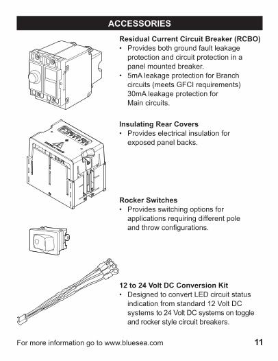
Residual Current Circuit Breaker (RCBO)• Provides both ground fault leakage protection and circuit protection in a panel mounted breaker.• 5mA leakage protection for Branch circuits(meetsGFCIrequirements) 30mAleakageprotectionfor Main circuits.
Insulating Rear Covers• Provides electrical insulation for exposed panel backs.
Rocker Switches• Provides switching options for applications requiring different pole andthrowconfigurations.
12 to 24 Volt DC Conversion Kit• Designed to convert LED circuit status indicationfromstandard12VoltDC systemsto24VoltDCsystemsontoggle and rocker style circuit breakers.

12 Formoreinformationgotowww.bluesea.com
ACCESSORIES
360 Panel Plugs• Usedtoplugblankcircuitbreakeraperture.
Push Button Reset-Only Circuit Breakers• Branch circuit breakers—can be used for 24-hourcircuitprotection.
Panel Switches• Toggle—Provides switching action other thanON-OFFordifferentpoleconfiguration separate from circuit protection.
Adapters• AdaptsToggleA-SeriesCircuitBreakers, PushButtonReset-OnlyCircuitBreakers, and Panel Switches to the circuit breaker apertureofthe360DistributionPanels.
• PushButton—Provides momentary switching action separate from circuit protection.

13Formoreinformationgotowww.bluesea.com
360 PANEL FUNCTIONS
AC and DC 60˚ Analog Meters• Monitorvoltsoramperes.• Backlitmeterface.
AC and DC Digital Meters• Monitorvolts,amperes,watts,frequency.•DCvoltagealarms,ACvoltageand amperage alarms.
AC and DC 90˚ Analog DIN Meters• Monitorvoltsoramperes.• Backlitmeterface.
SETMENU
V
AA 2.88
AC VOLTS
012525
50 75 100
150
Systems Monitor 1800• Monitorsvolts,amperes,watts, frequency,DCampere-hours.• Monitortanksandbilgecondition.• Alarmsforallmeasuredvalues.
360 Panels are built with modules providing the following functions:

14 Formoreinformationgotowww.bluesea.com
360 PANEL FUNCTIONS
2" Round Gauge• Monitorsengine,tanks,electrical,clock or hour meter values.
DC Push Button Reset-Only Circuit Breakers• Circuitprotectiononlyforun-switched 24-hourcircuitsorswitchesatotherlocations.
15
15
15
15 15
15
15
15
DC Push Button Reset-Only Circuit Breakers with Rocker Switches• Economicalswitchedcircuitprotectionfor low amp circuits.
DC 12 Volt Sockets• Twin12Voltreceptaclesintegratedintothe 360DistributionPanel.
10
10
10
10

15Formoreinformationgotowww.bluesea.com
360 PANEL FUNCTIONS
AC Multiple Source Slide Management• SafemanagementofmultipleACsources.• Available in rocker or toggle styles.
Rocker Style Circuit Breakers• Modernstyling,resistancetoaccidental switching and restricted switching models.• Availableinsingle,double,ortriplepole from5-300Amps.
Toggle Style Circuit Breakers• Foratraditionallookandfeel.• Available with black or white toggle breakers from5-50Amps.
m-Series Battery Switches• ON/OFF,Selector,DualCircuit™, andDualCircuitPlus™enable sophisticated battery management systems to be integrated into the 360DistributionPanel.

16 Formoreinformationgotowww.bluesea.com
360 PANEL FUNCTIONS
Blank Panel• Platformforavarietyofcontrolsand instruments that can be mounted into the360DistributionPanelforan integrated appearance.
AC Multiple Source Rotary Switch Management• SafemanagementofmultipleACsources with a fully backlit Rotary Switch AC management system.

17
BOOK LIST
Calder,Nigel.Boatowner’s Mechanical and Electrical Manual, third edition
Casey, Don. Sailboat Electrical Systems: Improvement, Wiring and Repair
Casey, Don. Sailboat Electrics Simplified
Payne, John C. The Fisherman’s Electrical Manual
Payne, John C. Understanding Boat Batteries and Battery Charging Payne, John C. Understanding Boat Wiring
Payne, John C. The Marine Electrical and Electronics Bible
Payne, John C. The Motorboat Electrical and Electronics Manual
Sherman, Ed. Powerboater’s Guide to Electrical Systems: Maintenance, Troubleshooting and Improvements
Sherman, Ed. Advanced Marine Electrics and Electronics Troubleshooting
Wing, Charlie. Boatowner’s Illustrated – Electrical Handbook, second edition

990343500Rev.001
GuaranteeAnyBlueSeaSystemsproductwithwhichacustomerisnotsatisfiedmaybe returned for a refund or replacement at any time.
ContactPhone: 360-738-8230Customer Service: TollFree1-800-222-7617Fax: 360-734-4195E-mail Address: [email protected] Address: www.bluesea.comHead Office Address: 425 Sequoia Drive Bellingham,Washington98226USA