installation manual - av-iq · pdf fileinstallation manual tabletop stand 3130 e. miraloma...
TRANSCRIPT

INSTALLATION MANUAL
TABLETOP STAND
3130 E. Miraloma Ave. Anaheim, CA 92806 Phone: 800 368-9700 Fax: 800 832-4888 www.mounts.com
PREMIER MOUNTS ©2004/ REV 00

- 2 -
o Safety & precautions o Stand diagrams o Parts list (1) o Flat panel list o Parts list (2) o Checking the thread depth on your flat panel o Building the stand o Securing the mounting brackets o Securing the flat panel to the stand o (Optional) fixed installation
The entire installation instructions should be fully read and understood, including all of the safety symbols and safety precautions before beginning installation. The installation instructions should be read, understood and followed to prevent personal injury or property damage. Keep these installation instructions in an easily accessible location for future reference.
Indicates that the power plug is to be disconnected from the power outlet.
Safety precautions must be taken at all times.
Contact Premier Mounts for any questions
Warning and caution in general
Do not install near heater, fireplace, direct sunlight or air conditioning or any other source of direct heat energy. Failure to do so may result in damage to the flat panel display and could cause a risk of fire.
At least two qualified people should always perform the installation work. Injury and damage can result from dropping or mishandling the flat panel display.
Contents
Safety & Precautions WARNING: Safety precaution measures must be practiced at all times during the installation of this product. Use proper safety gear and tools for the installations procedure to prevent personal injury or damage to the flat panel display mount.
The tabletop should be capable of supporting a max weight of 160 Lbs., the weight of the flat panel. More than 160 Lbs the tabletop must be reinforced. Proper installation procedure by qualified personnel as outlined in the installations instructions must be adhered to. Failure to do so could result in serious personal injury.

- 3 -
32.000(812)
30.590(776.9)
30.00(762)
27.746(704.7)
1.500(38.1)
Ø1.500(38.1)
8.271(210.0)
1.000(25.4)
PART#: PSD-TTS/C PSD-TTS COLOR: Silver A. Back cover B. Vertical brackets C. Mounting brackets D. Griplates™ & mounting hardware E. Aluminum block F. Base
Stand diagrams
Dimensions are in Inches and (mm)
A
B D
C
E F
Base dimensions: 1.00”(25.4) H x 30.00”(762) W x 13.0”(330) D

- 4 -
Parts list (1) All of these parts are used to install the mounting bracket. Make sure that none of these parts are missing before beginning installation. If there are parts missing stop the installation and contact Premier Mounts.
Griplates™ (8)
Thread depth indicator (1)
Aluminum block (1)
Mounting brackets (2)
Base (1)
Tubes (2)
Vertical brackets (2)
Back cover (1)
Allen key (1)
M5 x 10 Phillips screws (2)
M5 x 30 Phillips flat head screws (5)
Socket head Screws (6)
Tube caps (2)
Wood screws (2) (Optional use)
Rubber vinyl (4) (used on the PSD-TTS/C only)
Rubber feet (4) (used on the PSD-TTS only)
M6 Phillips screws (4)

- 5 -
Flat panel list
Hitachi
EIKI
Electrograph
Gateway
32HDT20,CMP307XJ,CMP307XU,32HDT20 CMP401HDU, CMP402HDE, CMP402HDU, CMP4120HDU,CMP4121,CMP4121HDU,CMP4201U, CMP4202U, 42HDW10,42HDT20, 42HDT50, 42HDT55 M6 x 16 CMP5000WXU, CMP5003WXU, 50HDT50, 50HDT55: M8 X 20 32HDT20, 32HDT50, 32HDT55, 32HDX60: M6 x 16
PLD42XU: M5 x 20 - ¼” nylon spacers (small) PLD32: M4 x 20
DTS42W: M8 x 30 – ¼” nylon spacers (large) DTS4230: M8 x 30 – ½” nylon spacers - sleeves DTS42DD, DTS42GBDD, DTS42GB: M6 x 20
GTWP42M102: M8 x 20, M8 x 35 – ¼” nylon spacers (large) GATEWAY 42: M8 x 30 – ¼” nylon spacers GATEWAY 46: M6 x 20 GATEWAY 50: M8 x 30 – ¼” nylon spacers
Acer
PDP7859: M6 x 20
Akai
CTA42AR7A, PDP4247, PDP4290, PDP4294, PDP5090, HPT500AN: M8 x 25 – ½” nylon spacers - sleeves
Albatron
PWV46AC: M6 x 20
Barco
Cineversum 50: M8 x 20 Solaris LC40: 8 x 30
Akira
EPM420, SV4201: M5 x 16
BenQ
PDP7843E: M6 x 20 – ¼” nylon spacers (small) PDP46W1: M6 X 16
Cornea
MP4200, MP4204: M5 x 16
Dream Vision
Revolution One, Revolution Five: M4 x 16
Eizo
5420T: M8 x 30
Dukane
P37: M6 x 16 P42: M6 x 16 P50: M8 x 20
Dwin
HD50: M8 x 30 – ½” nylon spacers - sleeves
Faroudja
FPP42HD10, FPP50HD10: M4 X 16
Fujitsu
4211, 4212, 4221, 4222, 4208, 4209, 4213, 4214, 4229, 4241,4242, 4233: M5 x 16 5001, 5002, 5003, 5004, P50XHA10, P50XCA11UH, P50XHA30WS: M8 x 25 – flat washers
Helios
4200: M8 x 20
Idex
PDM4260: M4 x 16
Ikegami
PTM4202: M5 x 20
Integra
PLA50V1: M4 X 16
JVC
GDV4200PZW, 4210, GDV4210PZWGA, 4211, GMP420UG, GMV42UG, JVP042WV74, PD42WV74, PD42WX84: M5 x 16 GDV500PZU, GDV501U, 502U: M8 X 30 – ½” nylon spacers – sleeves
LG Electronics
Flatron MU40PA10B, MU40PA15B: M5 x 20- ¼” nylon spacers Flatron MN42PZ10, MN42PZ11, MU42PZ10, MU42PZ11B, MU42PZ15B: M5 x 20 MU50PZ41, MU50PZ90: M5 x 20
Luce
PDTV4220A: M5 x 25 – ½” nylon spacers
Marantz
PD4280D, PD4282D, PD4290D, PD4292D, PD4293: M4 x 20 PD4298HD: M6 X 20 PD501OD, PD5020, PD5040:
Max
4600, 4600T: M6 x 20 5000: M8 x 30- ½” nylon spacers - sleeves
NOTE: If your flat panel display is not listed, go to (page 10) to determine the thread pitch on your flat panel.

- 6 -
SONY
Sanyo
VIEWSONIC
Sampo
PFM42B1,PFM42B2: M6 x 20 - 5/16” flat washers PFM-42V1,PFM-42V2: M6 x 20– 5/16” flat washers PFM50C1: M6 x 20 - 5/16” flat washers KE-42XBR900: M6 x 20 - 5/16” flat washers KE50XBR900: M6 x 20 - 5/16” flat washers KE42XS910: M6 x 20 - 5/16” flat washers KLV-30XBR900, KLV30MR1, LDM3000 KE32TS2U, KZ32TS1, PFM32C1, KE37XS910: M5 X 16 5/16” flat washer
PDP421A: M5 x 20 - ¼” nylon spacer (small) PDP42H1NA: M5 x 20 - ¼” nylon spacer (small) PDP32H1A: M5 x 20 – Nylon spacers
VPW420: M8 x 30 – ½” nylon spacers - sleeves VPW425: M8 x 30 – ¼” nylon spacers (large) VPW450HD: M8 x 30 – ¼” nylon spacers (large) VPW500: M8 X 20 VPW505: M8 x 30 – ¼” nylon spacers (large)
PME42S6: M8 x 30 – ¼” nylon spacers (large) PME42F61: M8 x 20, M8 x 35 – ¼” nylon spacers (large) PME50X6: M8 x 30 – ¼” nylon spacers (large)
Mitsubishi
PD5010HD, PD5030: M4 x 16
Monivision
PWV46AC, PD46W00: M6 x 20 PD3231, LWX30AMS: M6 x 16
NEC
4200W, 4210W, M4A,MP2, PX42M3A, 42PD1W, PD2 M5A,M5G, 42MP1, 42PD1, PX42VM1A, PX42VP1A, PX42VP2A, 42MP3, 42PD3, PX42VP3A, 42MP4, 42VP4A, 42MX2: M4 X 16, 5000W, PX50M5A, 50PD1, PX50VP1A, PX50MX1A, 50MP1, 50MP2, 50PD2, 50VP2, 50MP3, 50XM3: M4 X 16
Norcent
46WGA850: M6 x 16
Orion
PM4202: M5 x 16
Panasonic
TC42P1, PT42PD3P, PT42PD1P, TC42P1F, PT37P1, TH42PWD3, TH37PWD4UZ, PT37PD4, TH37PW5EX, TH37PA20UP, TH42PD4UY, TH42PWD4EX, PT42P1, 42PD2, TH42PWD3U, TH42PHD5U, PT42PD3P, PT42PD4, PT42PHD4P, TH42PWD5UY, TH42PW5UZ, TH42PWD6UY, TH42PA20UP, TH42PL20E, TH42PAX20, TH50PHD3U, PT50PD3P, PT50PHD4P, TH50PHD3E, TH50PHW3, TH50PD4, TH50PHD5UY, TH50PHD6UY, TH50PL20E, TH50TX20UP: M8 X 30 – ½” Nylon spacers – sleeves TH42PX20U, TH50PX20U: M8 X 70 – 1-1/2” Nylon spacers TC-32LH1: 4 x 25 – ½” Nylon spacers
Philips
42FD9934, 42FD9952, 42FD9954, 42PH9555, 42FD9935: M5 x 25 ½” Nylon spacers BDS4611: M6 x 20 50FD9934/17S: M4 X 16 34PW9847,30PW8859, 30PW8879, 30PW8869, 30PW9817, 34W9817, 37FD9954, 32FD9954, 32PF9954, 32PH995S, 30PF9975: M5 x 25 – ½” Nylon spacers
Pioneer
PDPV401, V402, PDP4330HD, PDP433HDE, PDP433CMX, PDP433PU, PDP4300, PDP4340HD, PRO800HD, PRO800HDI, PRO910HD, PDP4310, PDP501X, V502MX, V502X, PDP503MX, V505, PDP505HD, PRO1000HD, PDP503CMX, PDP5030HD, PDP503HDE, PDP5031HD, PDP5040HD, PRO1000HDI,PRO1110HD: M8 X 20
Planar
42N: M4 x 16 50P: M8 x 20
Princeton Graphics
AR3.4FTW,AR4.6PDP: M6 x 20
Rainbow
Spectrum 3750: M6 x 20
RCA
PR42300, PHD42600, PHD50300, PHD50400: M4 X 16 PHD50500: M8 X 20
Revox
E1042: M6 x 20 E1050: M8 x 20
Runco
PL42C, CW42: M4 X 16 PL42CXPL50CX: M8 X 30, ½” Nylon spacers – sleeves E1050, PL50C, PL50HDX, CW50MC: M8 X 20
Samsung
PPM42S2, PPM42S3, SPL4225K, SPN4235, SPN4239: SPK4215M, PK42P2S: M8 x 25 – ½” nylon spacers PPM50H2, HPL5025K: M8 x 30 – ½” Nylon spacers - sleeves PPM50H3, HPN5039: M8 x 25 – ½” nylon spacers
Sharp
PZ42H2U, PZ43HV2U, PD50U, PZ50HV2U: M8 X 20
Tatung
P46T: M6 x 20
Toshiba
42HP82: M4 X 16 PD42W, PD42W1: M8 X 30 – ½ ” nylon spacers (large) - sleeves 50HP81: M8 X 30 – ½” nylon spacers (large) - sleeves 50HP82: M4 X 16
SVA
HD4208TIII: M6 x 20 - ¼” nylon spacers
Tredex
TXP4600: M6 x 20
V-Inc
Vizio P1, Vizio P4: M6 x 16
Vidikron
VPW420: M8 X 30, ½” Nylon spacers (large) - sleeves
Yamaha
PDM1: M8 x 30 – ½” nylon spacers - sleeves
Zenith
DPDP40W, P40V22,DPDP40V, P40V24: M5 x 20 – ¼” nylon spacers (small) P42W22, P42W22B, P42W24P, P42W34P: P40V24: M5 x 20 – ¼” nylon spacers (small) P50W26, P50W28, P50W38: M5 x 16
NOTE: If your flat panel display is not listed, go to (page 9) to determine the
thread pitch on your flat panel.

- 7 -
Parts list (2) NOTE: This wall mount is shipped with all proper installation hardware and components. Make sure that none of these parts are missing before beginning installation. If there are parts missing stop the installation and contact Premier Mounts.
Actual screw size

- 8 -
1/4" Nylon spacers
5/16" Flat washers (metal)
1" Nylon spacers
1/4" Nylon spacers
9/16" Nylon spacers(large)
(small)
1/2" Nylon spacers(large) Nylon sleeves
(Qty 6)
(Qty 12)
(Qty 6)
(Qty 6)
(Qty 6)
(Qty 6)
(Qty 4)
Nylon spacers and flat washers actual size
NOTE: The nylon spacers may be stacked to achieve proper spacing.

- 9 -
Checking the thread depth on your flat panel
Inverted flat panel display
Thread insert
Thread depth indicator
Figure 2
Figure 3
Figure 1
Marking the depth
1. Insert the thread depth indicator (supplied) through the thread inserts found on the back of the flat panel to make sure the inserts measure the same full depth and mark it.
(see figure 1) 2. Locate the correct diameter
screw for the thread insert. Compare your marking to the screws (supplied). If your selected screw is longer than the marking on the thread depth indicator DO NOT USE this screw. The screw length must not bypass the marking. Select another screw size (see figure 2 and 3). Until you find one that comes closest to your mark without going past.
Marking
Screw
Marking
Thread depth indicator
- 10 -
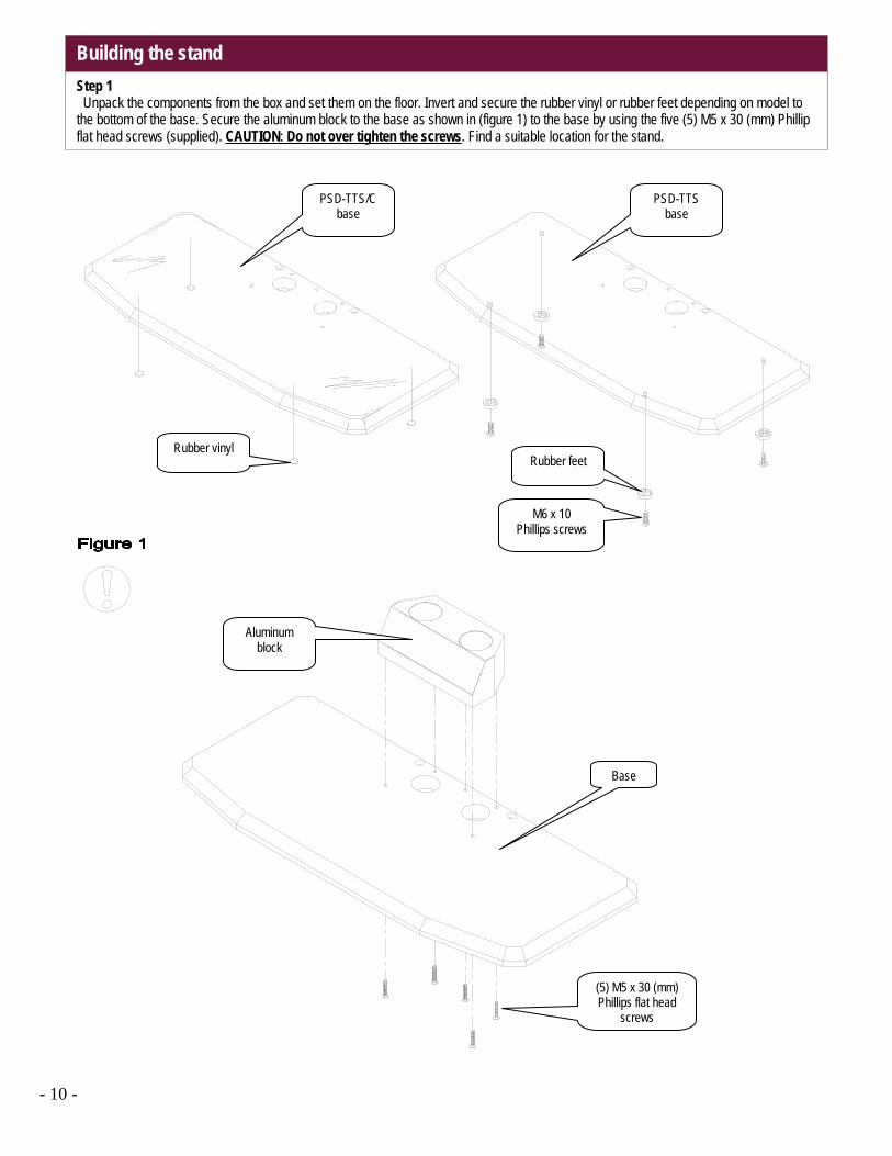
Building the stand
Step 1 Unpack the components from the box and set them on the floor. Invert and secure the rubber vinyl or rubber feet depending on model to the bottom of the base. Secure the aluminum block to the base as shown in (figure 1) to the base by using the five (5) M5 x 30 (mm) Phillip flat head screws (supplied). CAUTION: Do not over tighten the screws. Find a suitable location for the stand.
Aluminum block
Base
(5) M5 x 30 (mm) Phillips flat head
screws
PSD-TTS/C base
PSD-TTS base
Rubber vinyl Rubber feet
M6 x 10 Phillips screws

- 11 -
Step 2 Insert the tubes into the secured aluminum block. See diagram to set the cable access openings before tightening the set screws. See figure A. Once the poles are fully inserted into the block and set to their proper positions lock the tubes by tightening the two (2) M8 socket head screws. Do not over tighten the set screws. Install the plastic caps to the top of the tubes. See figure 2.
Plastic caps
Allen wrench
(2) M8 x 10 socket head screws
Base
Tubes
2 O’clock 10 O’clock
Tube location for cable access

- 12 -
Securing the mounting brackets Step 3 Invert the flat panel display and lay it on a soft and flat surface. Apply the vertical brackets and center the mounting brackets from left to right on the display. Secure the mounting brackets with the hardware and griplates™ (supplied). NOTE: The griplates™ come with an M4,M5,M6 and M8 access holes. Find out what your proper hardware for your flat panel will be and use accordingly. Do not over tighten the hardware.
(2) Mounting brackets Mounting hardware
(see charts) on page 5,6
(8) Griplates™ (supplied)
NOTE: All Griplates™ tips must be facing up
prior to installation.
(2) Vertical brackets
(4) M8x10 Socket head screws
Allen key
Flat panel display
Soft and flat surface
Nylon spacers
NOTE: See chart on page 5,6 (if the nylon spacers apply to
your flat panel).
NOTE: If your flat panel has more than four (4) mounting points use the
vertical brackets as shown on figure 3. Less than (6) mounting points, do not
use the vertical brackets.

- 13 -
Securing the flat panel to the stand Step 4 Raise the display (see warning on this page) and slide the mounting brackets over the tubes, set the height required and using the Allen wrench secure the height by tightening the four (4) M8 socket head screws. Do not over tighten the screws. Make all proper connections at this time. Install the back cover plate and secure it using two (2) M5 x 10 phillips screws (supplied). See figure 4.
Allen wrench
Back cover
(2) M5 x 10 phillips screws
WARNING: AT LEAST (2) QUALIFIED PERSONNEL ARE STRONGLY
RECOMMENDED FOR INSTALLATION OF THIS PRODUCT. FAILURE TO DO SO
COULD RESULT IN SERIOUS INJURY AND POSSIBLE DAMAGE TO THE FLAT PANEL.
Cable routing access points

- 14 -
(Optional) fixed installation Step 5 If securing to a wood table, secure the stand with the two (2) #10 x 1-3/4" wood screws (supplied). NOTE: Longer or shorter wood screws and or mounting hardware depending on your installation environment are (commercially available). See figure 5.
Wood screw access holes
#10 x 1-1/4” wood screws
Flat wood surface
#10 x 1-3/4” wood screws
Base

- 15 -

- 16 -