installation manual - abb ltd · installation manual issued: 08.12.2008 ... needed to simulate the...
TRANSCRIPT

Protection System Simulator SIM600
Installation Manual


Contents:
1. About this manual .................................................................................. 5
1.1. Copyrights ...................................................................................... 51.2. Trademarks .................................................................................... 51.3. Guarantee ...................................................................................... 51.4. General .......................................................................................... 51.5. Document conventions .................................................................. 61.6. Use of symbols .............................................................................. 61.7. Terminology .................................................................................... 71.8. Abbreviations ................................................................................. 71.9. Related documents ........................................................................ 81.10. Document history ........................................................................... 8
2. Product overview .................................................................................... 9
2.1. Protection System Simulator SIM600 overview ............................. 92.2. Hardware ..................................................................................... 112.3. SIM600 Editor .............................................................................. 112.4. SIM600 Runtime .......................................................................... 12
3. Installing software ................................................................................ 13
3.1. Software requirements ................................................................. 133.2. Installing SIM600 Editor and SIM600 Runtime ............................ 13
4. Connecting SIM600 to IED ................................................................... 17
4.1. Connecting binary I/O cables ....................................................... 174.2. Connecting analogue output cables ............................................ 194.3. Configuring the connectors .......................................................... 20
5. Mounting Protection System Simulator SIM600 ............................... 25
5.1. Mounting of Protection System Simulator SIM600 ..................... 25
6. Uninstalling SIM600 Editor and Runtime ........................................... 27
6.1. Uninstalling SIM600 .................................................................... 27
Index .............................................................................................................. 29
3
Protection System Simulator SIM6001MRS756102
Installation ManualIssued: 08.12.2008Version: B

4

About this manual1.
Copyrights1.1.
The information in this document is subject to change without notice and should not beconstrued as a commitment by ABB Oy. ABB Oy assumes no responsibility for anyerrors that may appear in this document.
In no event shall ABB Oy be liable for direct, indirect, special, incidental or consequentialdamages of any nature or kind arising from the use of this document, nor shall ABB Oybe liable for incidental or consequential damages arising from use of any software orhardware described in this document.
This document and parts thereof must not be reproduced or copied without written per-mission from ABB Oy, and the contents thereof must not be imparted to a third partynor used for any unauthorized purpose.
The software or hardware described in this document is furnished under a license andmay be used, copied, or disclosed only in accordance with the terms of such license.
© Copyright 2008 ABB. All rights reserved.
Trademarks1.2.
ABB is a registered trademark of ABB Group. All other brand or product names men-tioned in this document may be trademarks or registered trademarks of their respectiveholders.
Guarantee1.3.
Please inquire about the terms of guarantee from your nearest ABB representative.Factory warranty period of SIM600 is 1 year from product delivery.
General1.4.
This manual provides thorough information on installing SIM600 and the central conceptsrelated to it. For more information on configuring and using SIM600, refer to 1.9, Relateddocuments.
Information in this user's guide is intended for trainers, product demonstrators, marketers,and sales personnel.
5
Protection System Simulator SIM6001MRS756102
Installation Manual

SIM600 Editor and its logical symbols are in some parts in compliance with theIEC 61131–3 standard. Knowledge of the standard is an advantage when you work withthe editor and design the logic.
Document conventions1.5.
The following conventions are used for the presentation of material:• The words in names of screen elements (for example, the title in the title bar of a
window, the label for a field of a dialog box) are initially capitalized.• Capital letters are used for the name of a keyboard key if it is labeled on the keyboard.
For example, press the ENTER key.• Lowercase letters are used for the name of a keyboard key that is not labeled on the
keyboard. For example, the space bar, comma key, and so on.• Press CTRL+C indicates that you must hold down the CTRL key while pressing
the C key (to copy a selected object in this case).• Press ESC E C indicates that you press and release each key in sequence (to copy
a selected object in this case).• The names of push and toggle buttons are boldfaced. For example, click OK.• The names of menus and menu items are boldfaced. For example, the File menu.
• The following convention is used for menu operations: MenuName > Menu-Item. For example: select File > New.
• The Start menu name always refers to the Start menu on the Windows taskbar.
Use of symbols1.6.
This publication includes warning, caution, and information icons that point out safetyrelated conditions or other important information. It also includes tip icons to point outuseful information to the reader. The corresponding icons should be interpreted as follows.
The electrical warning icon indicates the presence of a hazardwhich could result in electrical shock.
The warning icon indicates the presence of a hazard whichcould result in personal injury.
The caution icon indicates important information or warningrelated to the concept discussed in the text. It might indicatethe presence of a hazard which could result in corruption ofsoftware or damage to equipment or property.
6
1MRS756102Protection System Simulator SIM600
Installation Manual

The information icon alerts the reader to relevant facts andconditions.
The tip icon indicates advice on, for example, how to designyour project or how to use a certain function.
Terminology1.7.
The following is a list of terms associated with SIM600 that you should be familiar with.The list contains terms that are unique to ABB or have a usage or definition that is dif-ferent from standard industry usage. See also 1.8, Abbreviations
DescriptionTerm
Peak value of a sinusoidal quantity.amplitude
A connector whose output signal is analogue.analogue output
Informs the IED of on/off states, such as discon-nector and circuit breaker states, alarm signalsor control functions.
binary output
Device providing connection and disconnectionto a suitable mating component.
connector
See "binary output".digital output
Connection points to a system. I/O can be digital(the signal is TRUE or FALSE, for example 0or 10 V) or analogue (where the signal can varyfrom for example 0 to 10 V).
Input/Output
A physical IEC 61850 device that behaves asits own communication node in the IEC 61850protocol.
Intelligent Electronic Device
Semiconductor that emits light.Light Emitting Diode
Measuring relay which, either solely or in com-bination with other relays, is a constituent ofprotection equipment.
protection relay
Abbreviations1.8.
The following is a list of abbreviations associated with SIM600 that you should befamiliar with. See also 1.7, Terminology.
DescriptionAbbreviation
Analogue outputAO
7
Protection System Simulator SIM6001MRS756102
Installation Manual

DescriptionAbbreviation
Digital outputDO
Graphical User InterfaceGUI
Human Machine InterfaceHMI
High-Speed Power OutputHSPO
Intelligent Electronic DeviceIED
Input/OutputI/O
Light Emitting DiodeLED
Personal ComputerPC
Power outputPO
Universal Serial BusUSB
Related documents1.9.
MRS numberName of the manual
1MRS756103Protection System Simulator SIM600 Operator'sManual
1MRS756239Protection System Simulator SIM600 Configur-ation Manual
Document history1.10.
HistoryProduct revisionDocument version/date
Document created1.0A/28.9.2007
Document updated1.0B/08.12.2008
8
1MRS756102Protection System Simulator SIM600
Installation Manual
Product overview2.
Protection System Simulator SIM600 overview2.1.
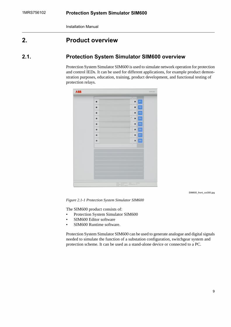
Protection System Simulator SIM600 is used to simulate network operation for protectionand control IEDs. It can be used for different applications, for example product demon-stration purposes, education, training, product development, and functional testing ofprotection relays.
SIM600_front_coi300.jpg
Figure 2.1-1 Protection System Simulator SIM600
The SIM600 product consists of:• Protection System Simulator SIM600• SIM600 Editor software• SIM600 Runtime software.
Protection System Simulator SIM600 can be used to generate analogue and digital signalsneeded to simulate the function of a substation configuration, switchgear system andprotection scheme. It can be used as a stand-alone device or connected to a PC.
9
Protection System Simulator SIM6001MRS756102
Installation Manual
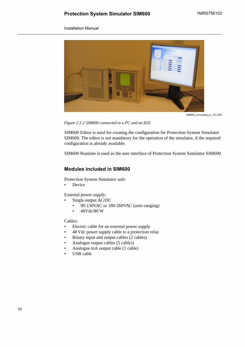
SIM600_connected_to_ PC.JPG
Figure 2.1-2 SIM600 connected to a PC and an IED
SIM600 Editor is used for creating the configuration for Protection System SimulatorSIM600. The editor is not mandatory for the operation of the simulator, if the requiredconfiguration is already available.
SIM600 Runtime is used as the user interface of Protection System Simulator SIM600.
Modules included in SIM600
Protection System Simulator unit:• Device
External power supply:• Single output AC/DC
• 90-130VAC or 180-260VAC (auto-ranging)• 48Vdc/80 W
Cables:• Electric cable for an external power supply• 48 Vdc power supply cable to a protection relay• Binary input and output cables (2 cables)• Analogue output cables (5 cables)• Analogue mA output cable (1 cable)• USB cable
10
1MRS756102Protection System Simulator SIM600
Installation Manual
Ordering information
SIM600AA.jpg
Figure 2.1-3 Ordering code for SIM600
Option available:• Package of cables: 5 Analogue + 1 mA cables• Ordering code: 1MRS090070
Mounting:• Ordering code: 1MRS050993
Commission order by ABB:• Current amplifiers (Tillquist)
• CXV30 Rogowski-Voltage to AC Current amplifier• Voltage amplifiers (Tillquist)
• Three-phase RHVD-voltage power-amplifier, type: PXV33-X-I/O V
Hardware2.2.
Protection System Simulator SIM600 is a microprocessor-based device that can be usedas a stand-alone device or connected to a PC. It can be configured in any way required.Protection System Simulator SIM600 consists of a central unit, housed in a metallic case.The central unit contains a USB-connection to a PC, eight pushbuttons, and 16 LEDindicators. For more information on connectors for SIM600, see 4.3, Configuring theconnectors.
SIM600 Editor2.3.
SIM600 Editor is used for configuring Protection System Simulator SIM600 for therequired task. SIM600 Editor is not mandatory for the operation of SIM600, if the requiredconfiguration is already available.
SIM600 Editor has two views, the GUI Editor and the IO Editor view.
GUI Editor
GUI Editor is used for drawing the user interface that includes all the functional objectsrequired by the application. The objects available are shown in the GUI Tools window
11
Protection System Simulator SIM6001MRS756102
Installation Manual

on the right of the GUI Editor view. Objects can be added to the workspace and theycan be freely moved within the area.
IO Editor
IO Editor is used to connect the objects displayed in the user interface and to specify thenecessary operation for SIM600. The workspace of IO Editor contains a list of input andoutput signals of SIM600. The IO Tools window on the right of IO Editor view containslogic symbols. Logic symbols are used in the same way as the objects in GUI Editor,that is, they can be added to the workspace as required.
For information on installing SIM600 Editor, see 3.2, Installing SIM600 Editor andSIM600 Runtime
SIM600 Runtime2.4.
SIM600 Runtime is used as the user interface of Protection System Simulator SIM600,especially if the eight pushbuttons and the 16 LEDs are not sufficient for the requiredfunctions. The configuration created with SIM600 Editor is loaded into Protection SystemSimulator SIM600 via SIM600 Runtime.
Runtime_example.jpg
Figure 2.4-1 An example view of SIM600 Runtime
12
1MRS756102Protection System Simulator SIM600
Installation Manual

Installing software3.
Software requirements3.1.
SIM600 Editor and SIM600 Runtime are compatible with MS Windows 2000 or newer.
Installing SIM600 Editor and SIM600 Runtime3.2.
To install SIM600 Editor and SIM600 Runtime:1. Insert the installation CD to your PC.2. Copy the PRS.exe and PRSEditor.exe files from the CD to the hard disk of your
PC. If you want to install only SIM600 Editor or SIM600 Runtime, copy theappropriate file to your PC.
You can run SIM600 Editor and SIM600 Runtime also directlyfrom the CD.
3. Connect your PC to Protection System Simulator SIM600 with the USB cable.4. The Found New Hardware Wizard opens. Select No, not this time to browse for
the correct software on your PC.5. Click Next.
driver_installation1.jpg
Figure 3.2-1 Searching for new software
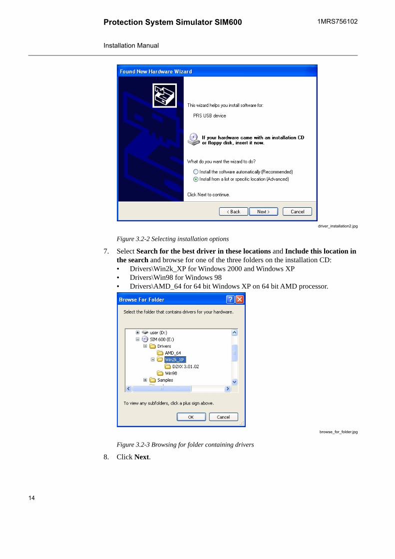
6. Select Install from a list or specific location (Advanced) and click Next to browsefor the drivers from the correct location.
13
Protection System Simulator SIM6001MRS756102
Installation Manual
driver_installation2.jpg
Figure 3.2-2 Selecting installation options
7. Select Search for the best driver in these locations and Include this location inthe search and browse for one of the three folders on the installation CD:• Drivers\Win2k_XP for Windows 2000 and Windows XP• Drivers\Win98 for Windows 98• Drivers\AMD_64 for 64 bit Windows XP on 64 bit AMD processor.
browse_for_folder.jpg
Figure 3.2-3 Browsing for folder containing drivers
8. Click Next.
14
1MRS756102Protection System Simulator SIM600
Installation Manual

driver_installation3.jpg
Figure 3.2-4 Searching for drivers
9. Wait while the wizard searches and installs the drivers.
driver_installation5.jpg
Figure 3.2-5 Installing drivers
10. Click Finish to close the wizard after the drivers have been installed.
15
Protection System Simulator SIM6001MRS756102
Installation Manual
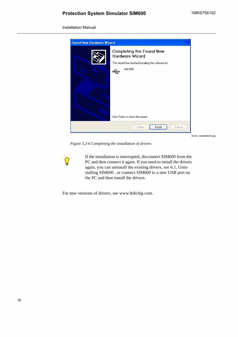
driver_installation6.jpg
Figure 3.2-6 Completing the installation of drivers
If the installation is interrupted, disconnect SIM600 from thePC and then connect it again. If you need to install the driversagain, you can uninstall the existing drivers, see 6.1, Unin-stalling SIM600 , or connect SIM600 to a new USB port onthe PC and then install the drivers.
For new versions of drivers, see www.ftdichip.com.
16
1MRS756102Protection System Simulator SIM600
Installation Manual

Connecting SIM600 to IED4.
Connecting binary I/O cables4.1.
Two binary I/O cables are delivered with the SIM600. These cables transfer binary datato and from the protection and control IED.
Each cable has three sets of plugs:
• four 3-pin plugs (X1 to X4) or digital outputs (DO) that transfer signals from SIM600to the IED
• two 4-pin plugs (X5 and X6) or digital inputs (DI) that transfer signals from the IEDto SIM600 and circuit breaker and disconnector trip signals (specifically designedfor connection to the High-Speed Power Outputs (HSPO) or the power outputs (PO)of the IED)
• six 2-pin plugs (X7 to X12) or digital inputs (DI) that transfer signals from the IEDto SIM600.
Connect the cables to the connectors labelled DIGITAL I/O 1 and DIGITAL I/O 2 onthe side panel of SIM600 Protection System Simulator. Connect the 3-pin connectors tothe IED binary inputs and the 4- and 2-pin connectors to the binary (signal) outputs ofthe IED.
DIO cable.jpg
Figure 4.1-1 Digital I/O cable set
17
Protection System Simulator SIM6001MRS756102
Installation Manual
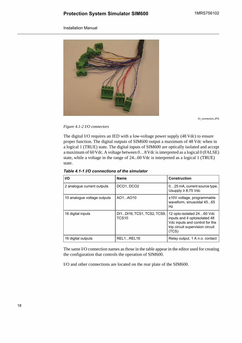
IO_connectors.JPG
Figure 4.1-2 I/O connectors
The digital I/O requires an IED with a low-voltage power supply (48 Vdc) to ensureproper function. The digital outputs of SIM600 output a maximum of 48 Vdc when ina logical 1 (TRUE) state. The digital inputs of SIM600 are optically isolated and accepta maximum of 60 Vdc. A voltage between 0…8 Vdc is interpreted as a logical 0 (FALSE)state, while a voltage in the range of 24...60 Vdc is interpreted as a logical 1 (TRUE)state.
Table 4.1-1 I/O connections of the simulatorConstructionNameI/O
0…25 mA, current source type,Usupply ≥ 8,75 Vdc
DCO1, DCO22 analogue current outputs
±10V voltage, programmablewaveform, sinusoidal 45...65Hz
AO1...AO1010 analogue voltage outputs
12 opto-isolated 24…60 Vdcinputs and 4 optoisolated 48Vdc inputs and control for thetrip circuit supervision circuit(TCS)
DI1...DI16, TCS1, TCS2, TCS9,TCS10
16 digital inputs
Relay output, 1 A n.o. contactREL1...REL1616 digital outputs
The same I/O connection names as those in the table appear in the editor used for creatingthe configuration that controls the operation of SIM600.
I/O and other connections are located on the rear plate of the SIM600.
18
1MRS756102Protection System Simulator SIM600
Installation Manual
Connecting analogue output cables4.2.
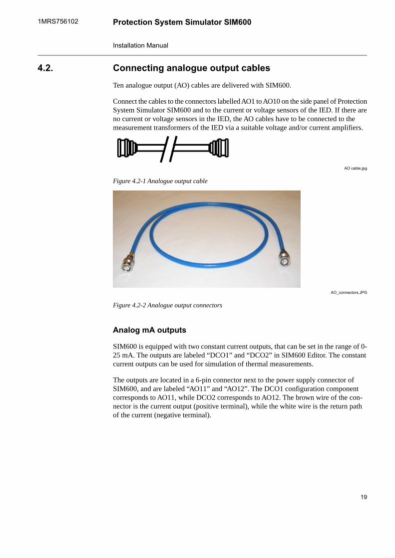
Ten analogue output (AO) cables are delivered with SIM600.
Connect the cables to the connectors labelled AO1 to AO10 on the side panel of ProtectionSystem Simulator SIM600 and to the current or voltage sensors of the IED. If there areno current or voltage sensors in the IED, the AO cables have to be connected to themeasurement transformers of the IED via a suitable voltage and/or current amplifiers.
AO cable.jpg
Figure 4.2-1 Analogue output cable
AO_connectors.JPG
Figure 4.2-2 Analogue output connectors
Analog mA outputs
SIM600 is equipped with two constant current outputs, that can be set in the range of 0-25 mA. The outputs are labeled “DCO1” and “DCO2” in SIM600 Editor. The constantcurrent outputs can be used for simulation of thermal measurements.
The outputs are located in a 6-pin connector next to the power supply connector ofSIM600, and are labeled “AO11” and “AO12”. The DCO1 configuration componentcorresponds to AO11, while DCO2 corresponds to AO12. The brown wire of the con-nector is the current output (positive terminal), while the white wire is the return pathof the current (negative terminal).
19
Protection System Simulator SIM6001MRS756102
Installation Manual

mA_cable2.JPG
Figure 4.2-3 mA cable
Configuring the connectors4.3.
Binary I/O connectors
The binary I/O connectors are represented in the IO Editor by components labelled RELand DI.
The 16 REL components correspond to the digital output connectors that transfer datato the IED, see Table 4.3-1.
Table 4.3-1 Binary I/O connectorsI/O connectorI/O cableREL component
X1DIGITAL I/O 1REL 1 - 2
X2DIGITAL I/O 1REL 3 – 4
X3DIGITAL I/O 1REL 5 – 6
X4DIGITAL I/O 1REL 7 - 8
X1DIGITAL I/O 2REL 9 - 10
X2DIGITAL I/O 2REL 11 – 12
X3DIGITAL I/O 2REL 13 – 14
X4DIGITAL I/O 2REL 15 – 16
To activate a REL component, apply a logical 1 (TRUE) signal to the input. To deactivatethe component, return the input signal to a logical 0 (FALSE level).
20
1MRS756102Protection System Simulator SIM600
Installation Manual

Digital input connectors
The 16 DI components correspond to the digital input connectors, see Table 4.3-1
Table 4.3-1 Digital output connectorsI/O connectorPlugI/O cableDI component
X54-pinDIGITAL I/O 1DI1
X64-pinDIGITAL I/O 1DI2
X72-pinDIGITAL I/O 1DI3
X82-pinDIGITAL I/O 1DI4
X92-pinDIGITAL I/O 1DI5
X102-pinDIGITAL I/O 1DI6
X112-pinDIGITAL I/O 1DI7
X122-pinDIGITAL I/O 1DI8
X54-pinDIGITAL I/O 2DI9
X64-pinDIGITAL I/O 2DI10
X72-pinDIGITAL I/O 2DI11
X82-pinDIGITAL I/O 2DI12
X92-pinDIGITAL I/O 2DI13
X102-pinDIGITAL I/O 2DI14
X112-pinDIGITAL I/O 2DI15
X122-pinDIGITAL I/O 2DI16
When connected properly, the DI1-2 and DI9-10 components output a logical 1 (TRUE)signal when inactive, whereas the other DI components output a logical 0 (FALSE) signalwhen inactive. When the IED outputs a signal, the states of these components switch.
Trip Circuit Supervision simulation is achieved with the TCS objects in SIM600 Editor.The fault simulation is activated by applying a logical 1 (TRUE) signal to the TCS objectinput. This causes the TCS of the corresponding 4-pin DI-component to be activated.
ConnectorTCS component
DI1TCS1
DI2TCS2
DI9TCS9
DI10TCS10
21
Protection System Simulator SIM6001MRS756102
Installation Manual

DIO cable connections.jpg
Figure 4.3-1 Digital output connections
22
1MRS756102Protection System Simulator SIM600
Installation Manual

AO Connectors
The AO connectors are represented in the IO Editor by the components labelled AO1through AO10. Each of these corresponds to the physical connector with the same label.
To logically output a signal, the chosen AO component is connected to the WF-outputof a SIN function block, either directly or through a MUX. The connected SIN block issupplied with an amplitude value and a phase value, upon which a sine wave is generatedand output using the frequency value assigned to the Freq component in the logic.
The value of the amplitude signal determines the value that is perceived by the IED. Theelectrical sine wave output has an amplitude maximum of 10 V. This amplitude isachieved by applying a value of 100 or higher to the amplitude input pin of the SINfunction block connected to the analogue output. The output amplitude can be calculatedby multiplying the value input to the amplitude pin of the SIN block by 100 mV. Thewave generation process responds to changes in the amplitude input value as small as0.01, corresponding to a 1 mV change in the actual output. The reading displayed by theIED does not solely depend on the transmitted analogue signal, but also on the settingsof the IED itself.
Depending on the load connected, the output of the analogueconnector may differ from the expected value. This can becorrected by altering either the IED settings, or the amplitudeinput value in the simulation configuration logic.
AO connection.bmp
Figure 4.3-2 AO connectors in IO Editor
Amplifier enable
The UIAMP_ENA object controls the AO amplifiers. When a logical 1 (TRUE) signalis applied to UIAMP_ENA, the AO amplifiers are powered up and able to output simu-lation signals. When a logical 0 (FALSE) signal is applied, the AO amplifiers are disabled.
23
Protection System Simulator SIM6001MRS756102
Installation Manual

Analog mA outputs
The simulation value for the analog mA outputs is applied directly to the DCOX I/Ocomponent. A value of 0 corresponds to 0 mA, while a value of 25 corresponds to 25mA. The 25 mA output is factory calibrated for an accuracy of 0.5%. However, theoutput current need not be linear over the 0-25 mA range and can thus differ considerably.If needed, the nonlinearity can be manually compensated in the simulation logic.
Analog mA output.bmp
Figure 4.3-3 Analog mA output logic
Auxiliary power supply
The UAUX_ENA object controls the IED auxiliary power supply output labeled “POWEROUT”, located next to the power supply connector of SIM600. When a logical 1 (TRUE)signal is applied to UAUX_ENA, the output powers up and is able to supply power at48 Vdc. When a logical 0 (FALSE) signal is applied, the output is disabled.
24
1MRS756102Protection System Simulator SIM600
Installation Manual
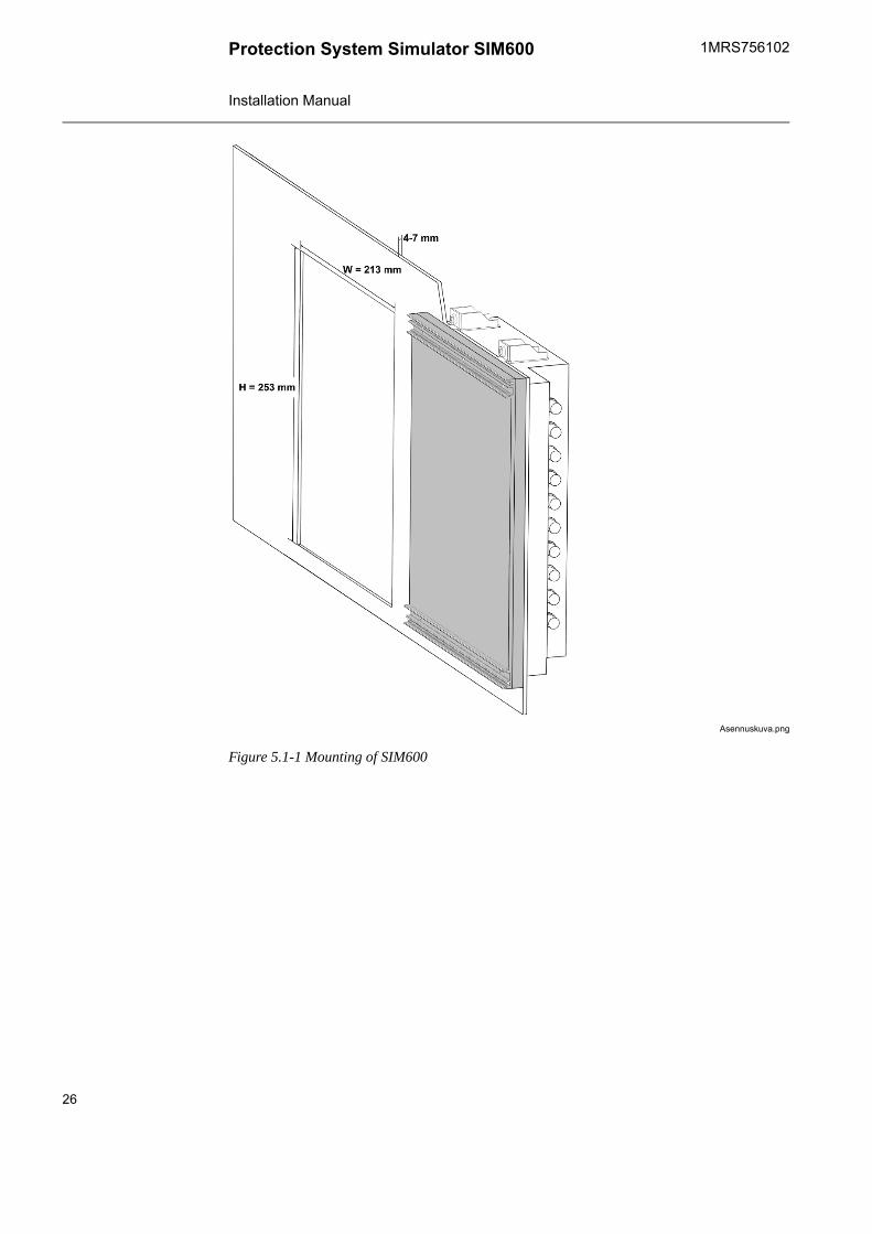
Mounting Protection System Simulator SIM6005.
Mounting of Protection System Simulator SIM6005.1.
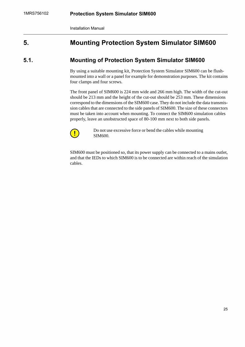
By using a suitable mounting kit, Protection System Simulator SIM600 can be flush-mounted into a wall or a panel for example for demonstration purposes. The kit containsfour clamps and four screws.
The front panel of SIM600 is 224 mm wide and 266 mm high. The width of the cut-outshould be 213 mm and the height of the cut-out should be 253 mm. These dimensionscorrespond to the dimensions of the SIM600 case. They do not include the data transmis-sion cables that are connected to the side panels of SIM600. The size of these connectorsmust be taken into account when mounting. To connect the SIM600 simulation cablesproperly, leave an unobstructed space of 80-100 mm next to both side panels.
Do not use excessive force or bend the cables while mountingSIM600.
SIM600 must be positioned so, that its power supply can be connected to a mains outlet,and that the IEDs to which SIM600 is to be connected are within reach of the simulationcables.
25
Protection System Simulator SIM6001MRS756102
Installation Manual
Asennuskuva.png
Figure 5.1-1 Mounting of SIM600
26
1MRS756102Protection System Simulator SIM600
Installation Manual

Uninstalling SIM600 Editor and Runtime6.
Uninstalling SIM6006.1.
You must have administrator rights to be able to uninstalldrivers.
To uninstall drivers:1. Select Start > Settings > Control Panel > System.2. In the System Properties window, select the Hardware tab.3. Click Device Manager.4. In the Device Manager window, open the Universal Serial Bus controllers structure.5. Right-click on the PRS USB Device and select Uninstall.
To uninstall SIM600 Editor and Runtime1. Disconnect Protection System Simulator SIM600 from your PC.2. Delete the PRS.exe and PRSEditor.exe files from the hard disk of your PC.
27
Protection System Simulator SIM6001MRS756102
Installation Manual

28

Index
Aanalog mA outputs .............................................................................................. 24AO connectors ................................................................................................... 23auxiliary power supply ......................................................................................... 24
Bbinary I/O connectors .......................................................................................... 20
Cconfiguring connectors ........................................................................................ 20connecting binary I/O cables ............................................................................... 17
Ddigital input connectors ....................................................................................... 21
Hhardware ............................................................................................................ 11
Iinstalling SIM600 Editor ....................................................................................... 13installing SIM600 Runtime ................................................................................... 13
Mmounting Protection System Simulator SIM600 .................................................... 25
SSIM600 Editor ..................................................................................................... 11SIM600 overview .................................................................................................. 9SIM600 Runtime ................................................................................................. 12
Uuninstalling SIM600 ............................................................................................ 27
29
Protection System Simulator SIM6001MRS756102
Installation Manual

30


1MR
S756
102
B
ABB Inc.ABB Oy655 Century PointDistribution AutomationLake Mary, Florida 32746P.O. Box 699USAFI-65101 VAASA
FINLAND Tel: +1 407 732 2000Tel. +358 10 22 11 Fax: +1 407 732 2335Fax. +358 10 22 1094www.abb.com/substationautomation