installation manual 2kw air heater diesel...
TRANSCRIPT

Installation Manual
2KW Air Heater
Diesel 12volt
Contents Page 1 Installation Manual Cover sheet & Contents Page 2 Preface Packing List Page 3 Introduction Technical Specifications Parts List Page 4 Heater Location Considerations
Fig 8 heater measurements 11 Heater mounting Fig 14 Fuel line & Flow & Notes
Page 5 Fig 15 Fuel Pump mounting Fig 17 Fuel pipe
Fig 20 Wiring diagram Notes on wiring Page 6 Item Locations
Step 1 - Fuel Tank Installation Step 2 - Installation of Fuel Filter & Pipe
Step 3 - Fitting the Fuel Pump Page 7 Step 4 - Heater Installation
Step 5 - Installation of Electrical System Figs 9 &10 Drilling templates & Fig 12 Cold Air Inlet & Hot Air Outlet piping
Page 8 Step 6 - Mount the Heater Step 7 - Connection the Air inlet & Exhaust pipes
Figs 22 & 23 Heater air intake & exhaust piping Page 9 Preparation for Initial test Run Page 10 Diesel heater control unit Basic Operation Page 11 Error Codes Page 12 Precautions Page 13 Typical Van Installation

Preface
Thank you for choosing 2KW air parking heater. This instruction book describes the structures, installation and operation of the heater. For correct use of the heater, please read this instruction book carefully before installation and use. The instruction book should be saved in a convenient place for later reference.
Attention: • This instruction book is subject to revision without notice. • Our effort is to explain all questions the users may have through this instruction book. If you have any
doubts or find anything incorrect-in this instruction book, please contact our company directly. • Unpacking, please check the heater and its accessories against the packing list. Please contact the
dealer immediately if any problem is found. • For any trouble arising during application, please contact our company or other customer
service stations authorized by our company. We shall do our best to provide service to you.
Packing List
No Name Specification QTY Purchase code
1 Heater 12V Gasoline, 12V Diesel, 24V Diesel
4W200212Q01 4W200212C01 4W200224C0
2 Wiring harness 1 12030300203
3 Fuse 12V/20A 24V/15A
1 11990002000 1990001900
4 Fuel pump 12V 12V with damper 24V
1 33000003100 33000007600 33000003200
5 Fuel pump connection wire L=6800 1 29030000400
6 Filter Only diesel 1 33000000400
7 Fuel pipe 2mm id / 5mm od L=8000 1 29030001300
8 Control switch With gasket 1 3l010700400
9 Protective cushion 1 12040600900
10 Air inlet pipe (with protective cover) 23mm id / 26mm od L=750 1 31010302600
11 Exhaust pipe (with protective cover) 22mm id / 28mm od L=700 1 31010302700
12 Gasket 81x110x2 1 12040001800
13 Reducing T 10-6-10 1 120200I5700
14 Fuel pump clip 32mm 1 I2010007100
15 Air inlet pipe clip 16mm / 25mm 1 12010004500
16 Exhaust pipe clip 22mm / 26mm 1 12010005000
17 Air inlet pipe fixing clip 24mm 2 29010003700
18 Exhaust pipe fixing clip 27mm 2 12010006100
19 Fuel pipe joint 4.1 id / 10.5 od L=50 6 12060003800
20 Fuel pipe clip 9mm id / 11mm od 12 12010004200
21 Fuel pipe clip 12mm id / 14mm od 2 12010004600
22 Washer 6mm id / 18mm od 4 12010006500
23 Nut M6 4 12050003400
24 Self drilling tapping screw ST5.5*25 4 12050003100
25 Self drilling tapping screw ST5.5*30 1 12050003100
26 Self tapping screw 4*16 1 12050002700
27 Self tapping screw 3*20 1 12050002500
28 Cable ties 4*200 10 21990000000
29 Oil suction pipe XYG-II 5*600 1 31000000500

Introduction The main equipment of Model 2KW air parking heater (referred to as the heater) is a small fuel furnace controlled by a single-chip micro- processor. Its furnace body (the heat exchanger) is located in the hood-shape case, which serves as independent air passage. Cold air is sucked into the air passage by the heat supplying fan and blown out when it becomes hot. This is an independent heating system for the vehicles. The heater is fully automatically controlled. It features in compact structure, easy installation, energy-saving, environmental protection, safety and reliability, easy maintenance, etc. Main Technical Specifications Please refer to Table 1 below for main technical specifications.
Heat Power (W) 2000
Fuel Gasoline Diesel
Rated Voltage 12V 12V/24V
Fuel Consumption 0.14-0.27 0.12-0.24
Rated Power Consumption (W) 14-29
Working (Environment) Temperature -40ºC to + 20 ºC
Working height above sea level <=1500m
Weight of main heater (kg) 2.6
Dimensions (mm) Length 323+-2, width 120+-1, height 121+-1
Mobile phone control (optional) No limitation (GSM network coverage)
Remote control (optional) Without obstacles <=800m
Diesel Heater Parts List
Note: Part No 13 the damper is not supplied or fitted (bypass)
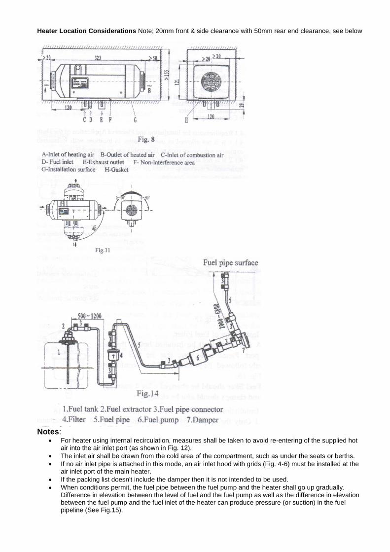
Heater Location Considerations Note; 20mm front & side clearance with 50mm rear end clearance, see below
Notes:
For heater using internal recirculation, measures shall be taken to avoid re-entering of the supplied hot air into the air inlet port (as shown in Fig. 12).
The inlet air shall be drawn from the cold area of the compartment, such as under the seats or berths.
If no air inlet pipe is attached in this mode, an air inlet hood with grids (Fig. 4-6) must be installed at the air inlet port of the main heater.
If the packing list doesn't include the damper then it is not intended to be used.
When conditions permit, the fuel pipe between the fuel pump and the heater shall go up gradually. Difference in elevation between the level of fuel and the fuel pump as well as the difference in elevation between the fuel pump and the fuel inlet of the heater can produce pressure (or suction) in the fuel pipeline (See Fig.15).

Conform to the requirements as follows: A-< 3m, B 0.5m (Avoid of negative pressure may be produced
in sealed fuel tank in such case, B < 0.15m, C <2m.
The outlet of the fuel pump shall tilt upwards. The tilt angle can be selected from the range of 15 °-- 35° see Fig. 15).
The fuel pump shall be fixed to the vehicle with a fuel pump clamp with protective rubber cover.
Check the vent on the fuel tank when doing installation.
Check fuel pipe after cutting for fuel flow (must use blade to cut, No Scissors or pliers.
The fuel pipe fittings supplied shall be used for connections between fuel pipe and fuel pump, fuel pipe and heater, fuel pipe and sucking pipe of fuel tank and fuel pipe and reducing T (T not used in some installations).
The fuel pipe shall be attached & clamps used.
Bubbles shall be eliminated from the fuel line (Fig. 17).
Note: When fuel is sucked from a fuel tank, a sucking pipe shall be used, good sealing is necessary for the base of the fuel sucking pipe. The bottom end of the fuel sucking pipe shall be 30mm-40mm from the bottom of the fuel tank.
Notes: The wires of the main heater for connection to outside circuits have been made into wire bundles. They can be laid according to the positions of various components and shall be fixed where necessary. The distance between two fixing points shall not exceed 30cm. Plugs used, should be inserted into terminal sockets where provided.

Item Locations You should 1st find suitable locations and facing position for the various items to be installed.
Determine the location for: 1. fuel tank, max distance tank to filter 1200mm, the Green tank supplied should be mounted vertically
because of the internal fuel pickup, 2. heater unit, allowing for clearances around the unit as specified See fig 8 & 11, mounted at a height to
ensure fuel pump & fuel line flows upward to the unit. 3. Ensure you have enough room around the heater to connect ducting & allowing for elbows to each side
of the heater if required see figs 9 & 10. 4. the warm air outlet ducting route to the rotatable vent & possibly a cool air inlet grill 5. fuel filter, you must be able to mount the filter in a near vertical position. See fig 14. 6. fuel pump, remember the fuel pump & line must be flow upwards. See fig 14. 7. control unit (display unit), easy to see and operate
Step 1 - Fuel Tank Installation Note: Clamps should be firm, do not over tighten Assumes installation of the supplied green 5 litre diesel tank.
1. Mount the green fuel tank vertically 2. Fit a short rubber fuel pipe connector (item 3 fig 14) to the tank and clamp off, do not over tighten the
clamp (firm). 3. Insert the clear nylon fuel line into the rubber fuel pipe connector then clamp off. 4. Run the fuel line to the filter.
Step 2 - Installation of Fuel Filter & Pipe Fit the fuel filter as per fig 14, ensure the filter is mounted with the arrow pointing up and in the direction of fuel flow to the pump.
1. Fit a short rubber fuel pipe connector to each side of the filter and clamp off. 2. Cut, fit and clamp the fuel line coming from the fuel tank to the bottom filter fuel pipe connector (inlet). 3. Fit the fuel line to the top of the filter (outlet) and clamp the rubber connector. 4. Run the fuel pipe from the filter to the fuel pump.
Step 3 - Fitting the Fuel Pump 1. Fit the fuel pump to the vehicle as per figs 14 & 15 and use the special metal/rubber strap provided. 2. Fit two short rubber fuel pipe connectors, one to each side of the pump and clamp off. 3. Cut, fit and clamp the fuel line coming from the filter to the pump. 4. The pipe from the fuel pump to the main heater must flow uphill. 5. Installation of Fuel Sucking Device (Fig. 18) not required when fitting the 5 litre green fuel tank

Step 4 - Heater Installation
1. Place the rubber gasket (Fig 9 part No11) where the heater is to be installed, using a marker pen trace the gasket and mark the 7 holes.
2. Drill the holes for the heater air inlet and heater exhaust, ensure that the hole are slightly oversize to allow the flex pipe fittings.
3. Good sealing is necessary between the main heater and the installation surface on the vehicle. 4. Fit special gasket (as shown in Fig. 8 part No 11) 5. Before mounting the heater fit the electrical cables as follows:
Step 5 - Installation of Electrical System Connecting the main wire bundle to the heater.
1. Use a blunt tool to pry the places marked "©"of Fig.4 gently to remove the junction box cover (Fig. 4-1). 2. Connect the 18-wire keyed connector X6 of the wire bundle to the controller socket & ensure it is push
fully home & clipped @ the top. The wire bundle can come out from either side of the heater. 3. Replace the junction box cover. Make sure to have good sealing between the junction box cover and
upper cover and between the junction cover box and the wire bundle sealing mat to- avoid any thermal malfunction due to leak of air from the hood-shape case.
4. Check for or Insert the fuse into fuse holder “F” and replace the upper cover tightly. 5. Attach the fuse holder to the vehicle using a screw. 6. You may wish to install a master on/off switch so as to be able to completely isolate the heater if not
connect the 2.5mm red wire and the 2.5 brown wire in the wire bundle to the hole terminals with springs and therefore connect to the and "-" terminals of the vehicle battery.
7. Fit the rubber mount to the rear of the control unit (Display). 8. At the control switch location drill a hole to allow the wire loom to pass through, it needs to be big
enough to allow the 3 plugs to pass through. 9. Fit the control switch in a position using screws. 10. The plugs on the leads from the control switch shall be connected with connector ( X9 & Xl0) according
to the colours on the main wire bundle, ensure they lock together. 11. The surplus wires and connectors in the wire bundle shall be wrapped with electrician's insulating tape
to avoid short-circuit or earthing.
Fig 9 Fig 10
Fig. 12
a) Correct b) Wrong

Step 6 - Mount the Heater
1. With the rubber seal in place on the bottom of the heater unit mount the heater in position. 2. Fit the nuts & washers provided and secure the heater. 3. Fit a short rubber fuel pipe connector to the heater fuel inlet & clamp off 4. Connect the cable coming from the air intake of the heater unit to the fuel pump. There is a 2 pin
extension cable provided if required. Plug the cable coming out of the air intake of the heater unit which passes through the opening in the wall of the air inlet pipe into the socket of the fuel pump. Note: cutting leads is forbidden.
5. DO NOT at this stage Cut, fit and clamp the fuel line leaving the pump to the heater. This will be done after the fuel flow test.
Notes: on the installation of combustion air inlet pipe and exhaust discharge pipe The combustion supporting air must be sucked in from external fresh air outside the vehicle.
The exhaust from combustion must be discharged into the air through exhaust pipe.
Measures must be taken to avoid the exhaust from re-entering the vehicle.
Measures must be taken to prevent entering of splash water.
The pipes must be protected and be able to resist shock.
Only the air inlet pipe and exhaust pipe provided with the heater can be used.
The air inlet pipe is a corrugated pipe made of aluminium pipe that it's surface is covered by plastic and paper;
The exhaust pipe is corrugated stainless steel pipe.
Please identify air inlet pipe and exhaust pipe and do not make mistake at installation.
Both the air inlet pipe and exhaust pipe shall come outwards and downwards from the heater (Fig. 22), otherwise a 04mm hole shall be prepared at the bottom of the pipe for discharge of condensation water. If the pipe needs bending, the radius cannot be smaller than 50mm. Also, the sum of all curve angles for each nine shall not exceed 270 degrees.
The openings of the pipes shall not be opposite to the direction of the running vehicle. (Fig. 23)
Arrangement of the pipes shall protect the pipe openings from blocking by slurry, rain and snow or other dirt.
When the heat is working, the exhaust pipe is at high temperature. In installation, make sure to install it in far distance from plastic parts or other objects with poor thermal resistance of the vehicle body.
The exhaust pipe shall be properly fixed.
The exhaust vent shall be downwards, perpendicular to the road surface with an angle of 90deg±10deg. To ensure such an angle, the fixing clamp for the exhaust pipe shall be within 150mm from the pipe end.
Step 7 - Connection the Air inlet & Exhaust pipes
1. Connect the air inlet pipe (part No 5) to the heater and clamp. 2. Carefully bend the air inlet pipe where required to position the inlet end in position see figs 22 & 23
below 3. Using the clamp or fittings provided secure the air inlet pipe to the vehicle, with the opened end
(hooded) facing rearwards. 4. Connect the exhaust outlet pipe (part No 8) to the heater and clamp. 5. Carefully bend the exhaust outlet pipe where required to position the outlet end (hooded) in position see
figs 22 & 23 below 6. Using the clamp or fittings provided secure the exhaust outlet pipe to the vehicle, with the opened end
facing rearwards.

Preparation for Initial test Run Assumes the heater is fully & correctly installed as per instruction manual and as indicated in fig 14 below. Please note: Item 7 the damper is neither supplied nor installed & the fuel pump extension cable is only used if required.
Final steps – Testing the Heater Setup
1. Ensure the dedicated diesel tank is full or if using an existing vehicle fitted tank ensure it has adequate fuel.
2. Remove the final rubber connector from the fuel input to the heater. (No3 top of picture in Fig 14) and place it in such a position that it will discharge fuel into a small container.
3. Select heater or air conditioner The heater has two operating modes: Select Heater or Air Conditioner
a. Fan, displays 35C (also known as Air condition mode).
b. Heater displays temperature P 01 to P 07 (heater range P01 minimum to P07 maximum). Note: your last change becomes the default
Switching Modes
4. Press On/Off (assumes no display visible wakeup)
5. Out of Box, 35C is displayed (Fan or Air Condition mode)
6. Within 5s Press On/Off again 7. Press ^ & v at same time 8. “P 07” (heater mode) displays
temperature setting range of P 01 to P 07 (min to max)
Note: your last change becomes the default. If the display indicates a P01 to P07 the unit is set to heater mode.
Pump Fuel through the fuel Line To START fuel pump Note # means a number between 0 & 7.
4. Press “P” to wake up display 5. Press "P", “P 0# “displayed for 5s ,
before then 6. Press "P" for more than 3s to enter
maintenance interface 7. "PO #" plus red maintenance /
confirm led displayed 8. Press "On/Off" for more than 3s 9. “FUEL” displayed & you can hear
the pump running
STOP the pump 10. Press “On/Off”, Pump Stops 11. Press “P” for more than 3s to return
to Standby mode. 12. Check for fuel in the fuel filter &
some fuel has been pumped into the small container at the end of the fuel line.
If no fuel is evident you need to check your work then repeat the fuel pump process.
13. Reconnect the rubber connector you disconnected in setup step 2.
The Heater is now ready for a test run
Test run the heater Heater Startup
1. Press “On/Off” - “P 07” is displayed 2. Press “On/Off” - “P 07” & “Flame”
icon is displayed The heater will now begin the startup process. You should hear the fan running and changing speed. The startup takes some minutes. Note: Until the heater has been running for about 3-4 minutes do not press any buttons on the display panel as this will generate error codes.
To end heater test run To turn the heater Off
1. Press “On/Off” The “Flame” icon goes out shortly followed by the Temperature display Note: the fan will continue to run until the heater has cooled and has no display. This concludes the initial heater test.
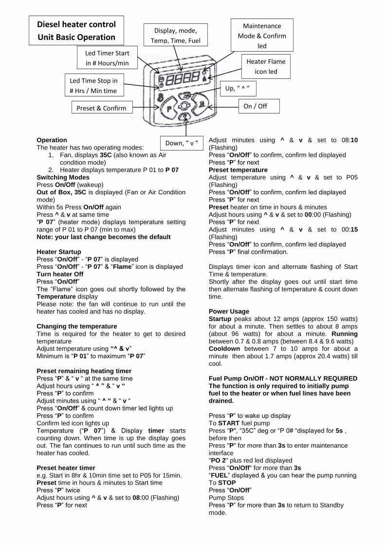
Operation The heater has two operating modes:
1. Fan, displays 35C (also known as Air condition mode)
2. Heater displays temperature P 01 to P 07 Switching Modes Press On/Off (wakeup) Out of Box, 35C is displayed (Fan or Air Condition mode) Within 5s Press On/Off again Press ^ & v at same time “P 07” (heater mode) displays temperature setting range of P 01 to P 07 (min to max) Note: your last change becomes the default Heater Startup Press “On/Off” - “P 07” is displayed Press “On/Off” - “P 07” & “Flame” icon is displayed Turn heater Off Press “On/Off” The “Flame” icon goes out shortly followed by the Temperature display Please note: the fan will continue to run until the heater has cooled and has no display. Changing the temperature Time is required for the heater to get to desired temperature Adjust temperature using “^ & v” Minimum is “P 01” to maximum “P 07” Preset remaining heating timer Press “P” & “ v “ at the same time Adjust hours using “ ^ ” & “ v “ Press “P” to confirm Adjust minutes using “ ^ “ & “ v “ Press “On/Off” & count down timer led lights up Press “P” to confirm Confirm led icon lights up Temperature (“P 07”) & Display timer starts counting down. When time is up the display goes out. The fan continues to run until such time as the heater has cooled. Preset heater timer e.g. Start in 8hr & 10min time set to P05 for 15min. Preset time in hours & minutes to Start time Press “P” twice Adjust hours using ^ & v & set to 08:00 (Flashing) Press “P” for next
Adjust minutes using ^ & v & set to 08:10 (Flashing) Press “On/Off” to confirm, confirm led displayed Press “P” for next Preset temperature Adjust temperature using ^ & v & set to P05 (Flashing) Press “On/Off” to confirm, confirm led displayed Press “P” for next Preset heater on time in hours & minutes Adjust hours using ^ & v & set to 00:00 (Flashing) Press “P” for next Adjust minutes using ^ & v & set to 00:15 (Flashing) Press “On/Off” to confirm, confirm led displayed Press “P” final confirmation. Displays timer icon and alternate flashing of Start Time & temperature. Shortly after the display goes out until start time then alternate flashing of temperature & count down time. Power Usage Startup peaks about 12 amps (approx 150 watts) for about a minute. Then settles to about 8 amps (about 96 watts) for about a minute. Running between 0.7 & 0.8 amps (between 8.4 & 9.6 watts) Cooldown between 7 to 10 amps for about a minute then about 1.7 amps (approx 20.4 watts) till cool. Fuel Pump On/Off - NOT NORMALLY REQUIRED The function is only required to initially pump fuel to the heater or when fuel lines have been drained. Press “P” to wake up display To START fuel pump Press "P", “35C” deg or “P 0# “displayed for 5s , before then Press "P" for more than 3s to enter maintenance interface "PO 2" plus red led displayed Press "On/Off" for more than 3s “FUEL” displayed & you can hear the pump running To STOP Press “On/Off” Pump Stops Press “P” for more than 3s to return to Standby mode.
Preset & Confirm On / Off
Led Time Stop in
# Hrs / Min time
Maintenance
Mode & Confirm
led
Heater Flame
icon led
Down, “ v “
Up, “ ^ “
Led Timer Start
in # Hours/min
time
Display, mode,
Temp, Time, Fuel
Diesel heater control
Unit Basic Operation

Heater Error Code Sheet
CODE ERROR DESCRIPITION ERROR LIGHT
00 No fault
10 Second starting failure F01
20 Combustion termination over times and stop F02
21 Combustion termination, shell and inlet temperature too small and restart
F02
30 Voltage over high F03
31 Voltage over low F03
41 Furnace temperature overhigh during self-check period F04
50 Flame sensor open circuit F05
51 Flame sensor short circuit F05
52 Hot air sensor open circuit F05
53 Hot air sensor short circuit F05
54 Hot air sensor overheat F05
65 Inside temperature sensor broken circuit F06
66 Inside temperature sensor short circuit F06
68 Outside temperature sensor broken circuit F06
69 Outside temperature sensor short circuit F06
70 Fuel pump short circuit F07
71 Fuel pump broken circuit F07
80 Fan broken circuit F08
81 Fan short circuit F08
82 Fan speed over low F08
83 Fan speed over high F08
84 Fan speed measurement fault F08
90 Glow plug broken circuit F09
91 Glow plug short circuit F09
92 Glow plug fault or resistance too large F09
93 Glow plug drive open circuit F09
a2 Inlet temperature overhigh during self-check period or furnace body temperature overhigh during heating process
F10
b4 Shell temperature broken circuit F11
b5 Shell temperature short circuit F12
c0 Warm blower relay open circuit F12
c1 Warm blower relay short circuit F12
c4 Preheating temperature broken circuit F12
c5 Preheating temperature short circuit F12
d0 Crystal oscillator in ECU failure F13
d1 Fault information storage failure F13
d3 Maintenance reminder F13
Precautions
1. After the heater is installed, in order to remove air trapped in the supply system thoroughly fill the fuel route with fuel only. See this manual on how to manually run the pump as you may be able to pump fuel to remove air from the lines.
2. Trial operation is necessary for the heater before it is put into normal use. At trial operation, you have to check leakage from all connections and all safety issues. If discharge of dense smoke is observed or irregular combustion noise or fuel smell is sensed, the heater must be turned off. Please take out the fuse, making the heater unable to operate. The heater can only be put into use after it is tested by qualified professionals.
3. Before each heating season, check shall be performed, details as follows: (a)Check air inlet and air outlet to find any pollution or foreign matters. (b) Clean the external of the heater. (c)Check if there is any corrosion or loose connection for electric contacts. (d)Check to find any clogging and damage to the air inlet pipe and exhaust pipe. (e)Check to find any leakage on the fuel pipe.
4. If the heater will not be in use for a long time, run it once every four weeks and let it run for 10 minutes at least to prevent malfunction of mechanical parts.
5. The air inlet port and air outlet vent of the heater must be kept clean and unblocked to provide smooth route for air flow, so as to prevent overheating.
6. If fuel is replaced with low-temperature fuel, run the heater for at least 15 minutes to fill new fuel into the fuel pipe and the fuel pump.
7. The heat exchanger of the heater cannot work for longer than 10 years. 8. If electric welding is performed on the vehicle, detach the positive wire of the power supply from the
battery and connect it to earth to protect the controller. 9. The ambient temperature shall be in the range of -40ºC to + 85 ºC for transport and storage of the heater to
avoid any damage to its electronic elements and components. 10. Only authorised customer service stations are allowed to provide repair and installation. 11. The manufacturer shall not be held responsible for any damage to the heater if the heater is opened without
authorization.
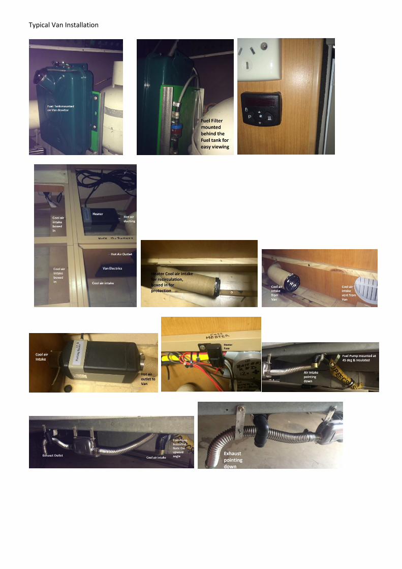
Typical Van Installation