installation instructions twinning kit for hsi single-and...
TRANSCRIPT
NOTE: Read the entire instruction manual before starting the installation.This symbol → indicates a change since the last issue.
TABLE OF CONTENTSSAFETY CONSIDERATIONS.....................................................................................................................................................................................1INTRODUCTION..........................................................................................................................................................................................................2DESCRIPTION AND USAGE .....................................................................................................................................................................................2ELECTROSTATIC DISCHARGE (ESD) PRECAUTION .........................................................................................................................................4SECTION I: MULTIPOISE SINGLE-SPEED AND TWO-SPEED NON-CONDENSING HSI FURNACE MODELS ........................................4
Install Furnaces.........................................................................................................................................................................................................4Upflow/Downflow, Side-by-Side Position .........................................................................................................................................................4Upflow/Downflow, Back-to-Back Position........................................................................................................................................................7Horizontal, Back-to-Back Position .....................................................................................................................................................................8Horizontal, Stacked Together ...........................................................................................................................................................................10
Connect Electrical Components—Heating ............................................................................................................................................................11All Single-Stage Models: 58STA, 58STX, 58DLA, 58DLX, 310AAV, 310JAV, 311AAV, 311JAV, PG8MAA, AND PG8JAAMultipoise Single-Speed Non-Condensing HSI Furnaces...............................................................................................................................11All Two-Stage Models: 58CTA, 58CTX, 312AAV, 312JAV Multipoise Two-Speed Non-Condensing HSI Furnaces with PSCMotors................................................................................................................................................................................................................15
Connect Electrical Components-Cooling...............................................................................................................................................................17Venting....................................................................................................................................................................................................................17Gas Supply Piping..................................................................................................................................................................................................17Electrical Supply Connections ...............................................................................................................................................................................17Start-Up and Adjustment........................................................................................................................................................................................19Sequence of Operation ...........................................................................................................................................................................................21
SECTION II: SINGLE-SPEED AND TWO-SPEED MULTIPOISE CONDENSING HSI FURNACE MODELS...............................................22Install Furnaces.......................................................................................................................................................................................................22
Upflow, Downflow, Side-By-Side Configuration............................................................................................................................................22Upflow/Downflow, Back-to-Back Configuration ............................................................................................................................................27Horizontal, Back-to-Back Configuration..........................................................................................................................................................28
Connect Electrical Components—Heating ............................................................................................................................................................30Connect Electrical Components—Cooling ............................................................................................................................................................33Venting....................................................................................................................................................................................................................34Gas Supply Piping..................................................................................................................................................................................................34Condensate Drain Connections ..............................................................................................................................................................................34Electrical Supply Connections ...............................................................................................................................................................................34Start-Up and Adjustment........................................................................................................................................................................................34Sequence of Operation ...........................................................................................................................................................................................36
Fixed Capacity Furnaces...................................................................................................................................................................................36
SAFETY CONSIDERATIONSInstalling and servicing of heating equipment can be hazardous due to gas and electrical components. Only trained personnel should install orservice heating equipment.Untrained personnel can perform basic maintenance such as cleaning and replacing filters. All other operations should be performed by trainedservice personnel. When working on heating equipment, observe precautions in the literature, on tags, and on labels attached to the unit.Follow all safety codes. Wear safety glasses and work gloves. Have a fire extinguisher available.Recognize safety information. This is the safety-alert symbol . When you see this symbol on the furnace and in instructions or manuals, bealert to the potential for personal injury.Understand the signal words DANGER, WARNING, CAUTION, and NOTE. These words are used with the safety-alert symbol. DANGERidentifies the most serious hazards which will result in severe personal injury or death. WARNING signifies a hazard which could result inpersonal injury or death. CAUTION is used to identify unsafe practices which would result in minor personal injury or product and propertydamage. NOTE is used to highlight suggestions which will result in enhanced installation, reliability, or operation.
Installation Instructions
KGATW0601HSITwinning Kit for HSI Single-and2-Stage Upflow Condensing andNon-Condensing Gas Furnaces
Catalog No.: AG-GATW-15 Cancels: AG-GATW-14 Printed in U.S.A. 10-05
→

CAUTION: UNIT DAMAGE HAZARDFailure to follow this caution could result in improper and dangerous operation.Label all wires prior to disconnection when servicing controls to prevent wiring errors.
INTRODUCTIONIMPORTANT: Only the furnace sizes listed in Tables 2, 3, and 4 can be twinned. Both furnaces must have the same product number, includingheating and cooling sizes, to achieve correct operation.
This furnace twinning kit P/N KGATW0601HSI permits connection to the following furnaces to operate as a single unit on the same duct work:
• 2 multipoise, 33.3 inch, single-speed, non-condensing furnaces (See Fig. 1, 2, and Table 2.)
• 2 multipoise, 33.3 inch, 2-stage, non-condensing furnaces (See Fig. 1, 12, and Table 2.)
• 2 upflow, 40 inch, single-speed, condensing furnaces (See Fig. 20, 21, and Table 3 or 4.)
• 2 upflow, 40 inch, 2-stage, condensing furnaces (See Fig. 20, 21, and Table 3 or 4.)
WARNING: UNIT AND PROPERTY DAMAGEFailure to follow this warning could result in unit and property damage.A non-condensing furnace shall NOT be twinned with a condensing furnace. Two stage condensing or non-condensing furnaces shallnot be twinned with any single stage furnace. Do not twin furnaces that have a different number of blower motor speed taps together.Furnaces shall only be twinned in the positions shown. Variable-speed furnaces shall not be twinned.
DESCRIPTION AND USAGERefer to the appropriate section for your furnaces.SECTION I: Models 58STA, 58STX, 58DLA, 58DLX, 310AAV, 310JAV, 311AAV, 311JAV, PG8MAA, and PG8JAA Multipoise Single-SpeedNon-Condensing HSI Furnaces• Single-Stage Heat with Single-Stage Gas-Heat Thermostat• Two-Stage Heat with 2-Stage Gas-Heat ThermostatModels 58CTA, 58CTX, 312AAV, and 312JAV, Multipoise 2-Stage Non-Condensing HSI Furnaces• Two-Stage Heat with Single-Stage Gas-Heat Thermostat• Two-Stage Heat with 2-Stage Gas-Heat ThermostatSECTION II: Models 58MCA, 58MCB, 58MSA, 58MXA, 58MXB, 340AAV, 340MAV, 345MAV, 350AAV, 350MAV, 490AAV, PG9MAA andPG9MAB Upflow Single-Speed Condensing HSI Furnaces• Single-Stage Heat with Single-Stage Gas-Heat ThermostatSECTION III: Models 58MTA, 58MTB, 352MAV and 352AAV Upflow 2-Stage Condensing HSI Furnaces• Two-Stage Heat with Single-Stage Gas-Heat Thermostat• Two-Stage Heat with 2-Stage Gas-Heat ThermostatDUCT CONNECTIONSAll furnaces must have a common supply plenum attached to the furnaces or evaporator coils prior to any branch supply trunk or take-off. Theheight of the plenum should be at least as high (upflow/downflow) or as long (horizontal) as the width of one furnace. Supply air dampers, whenused should be installed in the branch ducts, not in the common plenum. Fire or smoke dampers, when required by code may be installed in thecommon plenum. Refer to the damper manufacturer’s ratings installation instructions for proper application. The damper should not create unduerestriction in the open position.All furnaces must be installed to ensure sufficient return air to both furnaces:• For upflow furnaces: A combination of 1 full side of each and bottom inlet plenum or bottom only inlet plenum shall be used for return air
to each furnace. The preferred method is to have all return air brought into the bottom of the furnaces through a common bottom plenum. Thebottom return-air plenum shall be at least as high as the width of the furnace bottom return-air opening. When there are height limitations, thebottom return-air plenum height can be reduced to 8 in. minimum if 1 entire side return-air opening of each furnace is used in conjunction withthe bottom return opening. Rear inlet plenums shall not be used. (See Fig. 1.) Connect all return trunks or branch return ducts to common returnplenum.
• For downflow and horizontal furnaces: All return air must be brought into the bottom opening of the furnace through a common return airplenum. The return-air plenum shall be at least as long (horizontal) or tall (downflow) as the width of the furnace return-air opening. (See Fig.2) Connect all return trunks or branch return ducts to common return plenum.
• For all furnaces: Fire or smoke dampers, when required by code may be installed in the common return plenum. Refer to the dampermanufacturer’s ratings installation instructions for proper application. The damper should not create undue restriction in the open position.
WARNING: FIRE HAZARDFailure to follow this warning could result in improper auxiliary limit operation, fire, personal injury or death.Do not remove the center return-air partitions between the furnaces.
Staged heating operation is permitted only with this twinning kit. With the single-speed, non-condensing, and condensing furnaces, the left-handfurnace is used for first-stage heat, and both furnaces are used for second-stage heat. With the 2-stage, non-condensing and condensing furnaces,low-gas heat in both furnaces is used for first-stage heat, and high-gas heat in both furnaces is used for second-stage heat. This kit ensures bothfurnace blowers operate simultaneously so air flows through the duct work rather than recirculating in a loop between the furnaces.
—2—
→
→

Fig. 1—Upflow Ductwork Connections
A02223
��
�
�
�
�
���������� ��
���������������������
���������������������
�� �����
������������ ������������ ������������ ����������������� ������������ ���������� �������� ������
! "������������! ��#�����������! �����������! � �$���� ������������#������ �����
�%� �&��������'�( �������! ��������� ������ )�)�)�
������������� �*������� ��� ������ ����� �$+��+� �$,��������-����������./�������������������������������� ��������������0�1���� �������������� ������������ ����������������� ��
�� ����2
3(.45 ���������������������
���������������
������������������������� ��
���������������������
Fig. 2—Downflow/Horizontal Ductwork Connections
A02224
��
�
�
�
�
�
���������������������
���������������������
���������� ���
���������������������
���������������������
����������� ����� �$��6,37805"9-
�� ����:+1���;�� ������� �����
������������� �&����������������� ���� ������������ ��!&������ �$���������#���� ����������� �������*������� ��� ������ ��������+��+����,��������-)������������������������ �!&������������&��������'�(�����%� ������������������������� ��
������������� �&����������������� ���� ��������������� ��������������� �������� ������
�� ����<+&������������� �����
—3—

NOTE: As a result of staged heating with single-speed furnaces, the air temperature distribution in the supply plenum may be uneven when only1 furnace is heating.NOTE: Refer to the Installation, Start-Up, and Operating Instructions supplied with each furnace for information on venting, clearances, start-up,maintenance, and other information not covered in this publication.See Table 1 for kit contents.
ELECTROSTATIC DISCHARGE (ESD) PRECAUTION
CAUTION: UNIT AND COMPONENT DAMAGE HAZARDFailure to follow this caution could result in unit and component damage.Electrostatic discharge can affect electronic components. Take precautions during furnace installation and servicing to protect thefurnace electronic control. Precautions will prevent electrostatic discharges from personnel and hand tools which are held during theprocedure. These precautions will help to avoid exposing the control to electrostatic discharge by putting the furnace, the control, andthe person at the same electrostatic potential.
1. Disconnect all power to the furnace. DO NOT TOUCH THE CONTROL OR ANY WIRE CONNECTED TO THE CONTROL PRIORTO DISCHARGING YOUR BODY’S ELECTROSTATIC CHARGE TO GROUND.
2. Firmly touch a clean, unpainted, metal surface of the furnace chassis which is close to the control. Tools held in a person’s hand duringgrounding will be satisfactorily discharged.
3. After touching the chassis you may proceed to service the control or connecting wires as long as you do nothing that recharges your bodywith static electricity (for example; DO NOT move or shuffle your feet, DO NOT touch ungrounded objects, etc.).
4. If you touch ungrounded objects (recharge your body with static electricity), firmly touch furnace again before touching control or wires.
5. Use this procedure for installed and uninstalled (ungrounded) furnaces.
6. Before removing a new control from its container, discharge your body’s electrostatic charge to ground to protect the control from damage.If the control is to be installed in a furnace, follow items 1 through 5 before bringing the control or yourself into contact with the furnace.Put all used AND new controls into containers before touching ungrounded objects.
7. An ESD service kit (available from commercial sources) may also be used to prevent ESD damage.
SECTION I: MULTIPOISE SINGLE-SPEED AND TWO-SPEED NON-CONDENSING HSI FURNACE MODELSSINGLE-STAGE SINGLE-STAGE TWO-STAGE TWO-STAGE
58STA 310AAV 58CTA 312AAV
58STX 310JAV 58CTX 312JAV
58DLA 311AAV
58DLX 311JAV
PG8MAA
NOTE: Throughout these instructions, when the furnace installed side-by-side, the left-hand (LH) side will be referred to as the LH furnace, andthe furnace installed on the right-hand (RH) side as the RH furnace. When the furnaces are installed back-to-back, the left-hand (LH) side willbe referred to as the LH furnace, and the furnace installed on the right-hand (RH) side as the RH furnace when viewed from the side with theextension harness installed.
PROCEDURE 1—INSTALL FURNACES
A. Upflow/Downflow, Side-by-Side Position
Refer to Fig. 3 and Table 2 for appearance and dimensional drawing of twinned furnaces and their connection locations.
1. Select 2 identical heating and airflow furnaces. (See Table 2.)
Table 1—Kit Contents
Sealing tape 2External extension harness 327957-701 1Main twinning harness 327957-701 1Secondary twinning harness 327959-701 1Two stage furnace wiring diagram 327891-101 1Single Stage furnace heat wiring diagram 327893-101 1Single Stage furnace/Two stage heat wiring diagram 327892-101 1Label 327956-101 1Tape 1
Bag Assembly includes:Snap bushing 2Screws (HEX HD 6B X 3/4) 10Bag Assembly Includes:Snap bushing 2Screws (HEX HD 6B x 3/4) 10Screws (flat head) 1Wire tie 4Clamps 2
Installation Instructions 1
—4—
→

2. Remove outer door and blower access door.3. For upflow and downflow applications:
a. For upflow applications:Bottom return air usage is required as part of any upflow return air configuration. If additional return air is to enter 1 side of eachfurnace, in addition to bottom return air, cut open 1 entire return-air opening in appropriate side of each furnace. (See Fig. 1.)
WARNING: UNIT DAMAGE AND FIRE HAZARDFailure to follow this warning could cause fire, personal injury, or death.DO NOT use the back of the furnace for return-air duct connections in upflow position, as limit cycling will occur.
b. For downflow applications:Return air can only be connected to bottom opening of furnace. A common return air plenum is required for proper auxiliary limit switchoperation. (See Fig. 2.)
WARNING: UNIT DAMAGE AND FIRE HAZARDFailure to follow this warning could result in unit damage, fire, personal injury or death.DO NOT use the back or sides of the furnace for return-air duct connections in the downflow position, as limit switch cycling will occur.
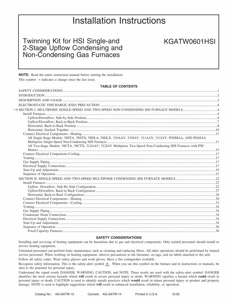
4. Remove bottom closure panels from both furnaces. (See Fig. 4.)a. Lay furnaces on back or sides.
b. Remove 2 screws from bottom front panel.
c. Rotate front panel downward to remove.
d. Remove bottom closure panel and discard.
e. Reinstall bottom front panel.
f. Stand furnaces upright.
5. Apply 2 factory-supplied foam strips to mating side of each furnace. Locate strips equal distance from top and bottom as shown in Fig. 5.Trim off excess material.
Fig. 3—Dimensional Drawing
A02235
AD
E
AD
E
Table 2—Dimensions (IN.) for Two-Stage with PSC Blower
UNIT SIZE A B C VENT CONN.* SHIP WT. (LB)045-08/024045 14–3/16 12–9/16 12–11/16 4 116
045-120/036045 14–3/16 12–9/16 12–11/16 4 117
070-08/024070 14–3/16 12–9/16 12–11/16 4 120
070-12/036070 14–3/16 12–9/16 12–11/16 4 126
070-16/048070 17–1/2 15–7/8 16 4 135
090-14/042090 17–1/2 15–7/8 16 4 137
090-16/048090 21 19–3/8 19–1/2 4 150
090-20/060090 21 19–3/8 19–1/2 4 155
110-12/036110 17–1/2 15–7/8 16 4 145
110-16/048110 21 19–3/8 19–1/2 4 157
110-22/066110 21 19–3/8 19–1/2 4 162
135-16/048135 21 19–3/8 19–1/2 4 162
135-22/066135 24–1/2 22–7/8 23 4 174
155-20/060155 24–1/2 22–7/8 23 4 181
5” or 6” vent connector may be required in some cases
—5—
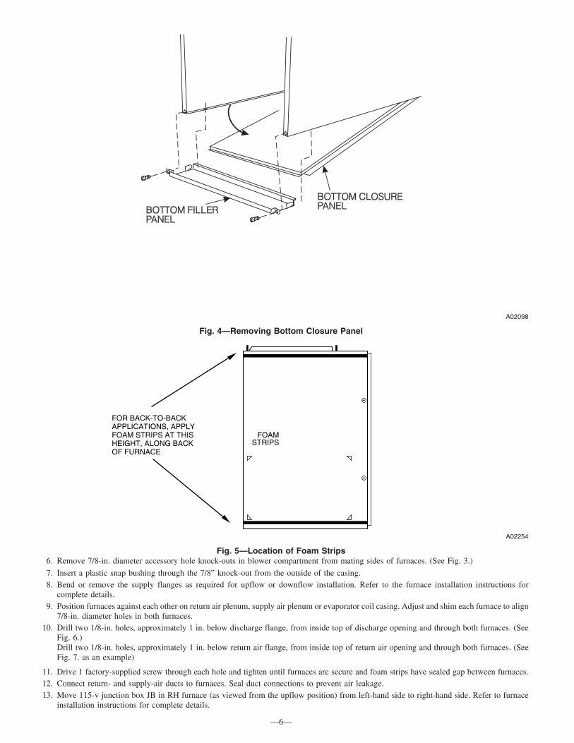
6. Remove 7/8-in. diameter accessory hole knock-outs in blower compartment from mating sides of furnaces. (See Fig. 3.)
7. Insert a plastic snap bushing through the 7/8” knock-out from the outside of the casing.8. Bend or remove the supply flanges as required for upflow or downflow installation. Refer to the furnace installation instructions for
complete details.9. Position furnaces against each other on return air plenum, supply air plenum or evaporator coil casing. Adjust and shim each furnace to align
7/8-in. diameter holes in both furnaces.10. Drill two 1/8-in. holes, approximately 1 in. below discharge flange, from inside top of discharge opening and through both furnaces. (See
Fig. 6.)Drill two 1/8-in. holes, approximately 1 in. below return air flange, from inside top of return air opening and through both furnaces. (SeeFig. 7. as an example)
11. Drive 1 factory-supplied screw through each hole and tighten until furnaces are secure and foam strips have sealed gap between furnaces.12. Connect return- and supply-air ducts to furnaces. Seal duct connections to prevent air leakage.13. Move 115-v junction box JB in RH furnace (as viewed from the upflow position) from left-hand side to right-hand side. Refer to furnace
installation instructions for complete details.
Fig. 4—Removing Bottom Closure Panel
A02098
Fig. 5—Location of Foam Strips
A02254
FOAMSTRIPS
FOR BACK-TO-BACKAPPLICATIONS, APPLYFOAM STRIPS AT THISHEIGHT, ALONG BACK OF FURNACE
—6—

14. Go to PROCEDURE 2A for Single Stage Furnaces or PROCEDURE 2B for Two Stage Furnaces.
B. Upflow/Downflow, Back-to-Back Position
Refer to Fig. 3 and Table 2 for appearance and dimensional drawing of twinned furnaces and their connection locations.
1. Select 2 identical heating and airflow furnaces. (See Table 2.)
2. Remove outer door and blower access door.
3. Remove bottom closure panels from both furnaces. (See Fig. 4.)
a. Lay furnaces on back or sides.
b. Remove 2 screws from bottom front panel.
c. Rotate front panel downward to remove.
d. Remove bottom closure panel and discard.
e. Reinstall bottom front panel.
f. Stand furnaces upright.
4.
a. For upflow applications:Bottom return air usage is required as part of any upflow return air configuration. If additional return air is to enter 1 side of each furnace,in addition to bottom return air, cut open 1 entire return-air opening in appropriate side of each furnace. (See Fig. 2.)
WARNING: UNIT DAMAGE AND FIRE HAZARDFailure to follow this warning could result in unit damage, fire, personal injury or death.DO NOT use the side of the furnace for return-air duct connections in the downflow position, as limit cycling will occur.
b. For downflow applications:Return air can only be connected to bottom opening of furnace. A common return air plenum is required for proper auxiliary limit switchoperation. (See Fig. 3.)
5. Apply 2 factory-supplied foam strips to the back of each furnace. Locate strips equal distance from top and bottom as shown in Fig. 5. Trimoff excess material.
6. Determine which side of furnace will be used to route external extension harness. Remove 7/8-in. diameter accessory hole knockouts inblower compartment side selected to attach harness to. (See Fig. 3.)
7. Bend or remove the supply flanges as required for upflow or downflow installation. Refer to the furnace installation instructions forcomplete details.
8. Position furnaces back-to-back on return-air plenum, supply air plenum or evaporator coil casing. Adjust and shim each furnace to alignboth furnaces.
NOTE: External extension harness cannot be used on the same side of the furnace that the return air ducts connect to. Locate harness on oppositeside of furnace when side return air is used.
9. Drill two 1/8-in. holes, approximately 1 in. below discharge flange, from inside top of discharge opening and through both furnaces. (Similarto Fig. 6.)Drill two 1/8-in. holes, approximately 1 in. below return air flange, from inside top of return air opening and through both furnaces. (Similarto Fig. 7.)
10. Drive 1 factory-supplied No. 6 X 3/4-in. LG screw through each hole and tighten until furnaces are secure and foam strips have sealed gapbetween furnaces.
11. Connect return- and supply-air ducts to furnaces. Seal duct connections to prevent air leakage.
12. Move 115-v junction box JB in either furnace from left-hand side to right-hand side if required. Refer to furnace installation instructionsfor complete details.
A02232Fig. 6—Attaching Furnaces Together at Discharge Opening
A02219Fig. 7—Attaching Furnaces Together at Return Air Opening
—7—
→

13. Go to PROCEDURE 2A for Single Stage Furnaces or PROCEDURE 2B for Two Stage Furnaces.
C. Horizontal, Back-to-Back Position
When twinning furnaces in the horizontal position, consideration must be made to the type of building construction. Attic floors should beconstructed to support normal live and dead loads of the furnaces and the person(s) servicing them.
Trusses, wood and metal are engineered for specific applications, and may not support the weight of two (2) furnaces suspended from the topchords or the bottom chords of the trusses. Long horizontals spans may flex or sag, resulting in damage to the building. Contact the trussmanufacturer for additional design and engineering assistance.
Do not suspend furnaces with straps or suspend furnaces from roof decking.
For attic installations on a platform (See Fig. 8a.):
1. Construct a platform from ¾″ (nominal plywood), extending out 30 inches from the front of each furnace.
2. Maintain all clearances to combustibles per the furnace Installation, Start-up and Operating Instructions.
3. Follow all additional building codes.
4. Long truss spans may require additional support along the bottom chord of the truss. Consult the truss manufacturer’s guidelines forengineering assistance.
5. Long rafter or attic joist spans may require additional support along the bottom of the rafter or joist. Consult local or regional building codesfor design and loading requirements.
For suspended installations (See Fig. 8b. Not recommended for wood trusses unless approved by the truss manufacturer or other approvedengineering methods):
1. Furnaces may be suspended using two (2) pieces of 1 ½” x 1 ½” x ¼” thick cold rolled angle iron underneath the furnaces and four (4)3/8″ diameter threaded rods.
2. Allow for at least nine (9) inches in front of each door for door removal.
3. Each piece of angle iron must be secured to the bottom of each furnace with at least two (2) #8 x ¾″ sheet metal screws.
4. Maintain all clearances to combustibles per the furnace Installation, Start-up and Operating Instructions.
5. Unistrut or similar material may be used, provided that the furnaces do not sag in the middle or bend or twist at the support ends. The supportmaterial must be secured to the bottom of each furnace in a manner similar to securing angle iron to the furnace.
Fig. 8a—Attic Installtion of Horizontal Back-to-Back Furnaces
A02241
30˝ Work Platform
Dripleg
Dripleg
Extension Harness
Gas Supply Shut-off
Gas Supply Shut-off
Gas Pipe Union
Gas Pipe Union
30˝ Work Platform
Sheet Metal
Same As Installation Instructions22˝
12˝
4 3/4˝
1˝
173/4˝ over all 4 3/4˝ under door1˝ under furnace
Extend out 12˝ from faceof door
3/8˝ Lock Washer
3/8˝ Flat Washer
3/8˝ Flat Washer
3/8˝ Lock Washer
3/8˝ Hex Nut
3/8˝ Hex Nut
3/8˝ Threaded Rod
1 1/2˝ x 1 1/2˝ x 1/4˝ Angle Iron
—8—

Refer to Fig. 3 and Table 2 for appearance and dimensional drawing of twinned furnaces and their connection locations.
1. Select 2 identical heating and airflow furnaces. (See Table 2.)
2. Remove outer door and blower access door.
3. Remove bottom closure panels from both furnaces. (See Fig. 4.)
a. Lay furnaces on back or sides.
b. Remove 2 screws from bottom front panel.
c. Rotate front panel downward to remove.
d. Remove bottom closure panel and set aside for possible use as roll-out protection.
e. Reinstall bottom front panel.
f. Stand furnaces upright
Fig. 8b—Suspended Installation for Horizontal Furnaces Back-to-Back
A02200
Twinning KitExtension Harness
3/8” Threaded Rod
See detail
Secure angle Iron to bottom of furnacewith at least (2) #8 x 3/4” sheet metalscrews in each furnace
1 1/2” x 1 1/2” x 1/4” Angle Iron
9” minimum for door removalon both sides of furnace
3/8˝ Lock Washer
3/8˝ Flat Washer
3/8˝ Flat Washer
3/8˝ Lock Washer
3/8˝ Hex Nut
3/8˝ Hex Nut
3/8˝ Threaded Rod
1 1/2˝ x 1 1/2˝ x 1/4˝ Angle Iron
—9—

4. For All Horizontal applications:Return air can only be connected to bottom opening of furnace. (See Fig. 2.) A common return air plenum is required for proper auxiliarylimit switch operation.
WARNING: UNIT DAMAGE AND FIRE HAZARDFailure to follow this warning could result in unit damage, fire, personal injury or death.DO NOT use the side or back of the furnace for return-air duct connections in the horizontal position, as limit cycling will occur.
5. Apply 2 factory-supplied foam strips to the back of each furnace. Locate strips equal distance from top and bottom as shown in Fig. 5. Trimoff excess material.
6. Determine which side of furnace will be used to route external extension harness. Remove 7/8-in. diameter accessory hole knockouts inblower compartment side selected to attach harness to. (See Fig. 3.)
7. Position furnaces back-to-back on attic platform or suspended supports. Adjust and shim each furnace to align both furnaces. Follow allclearance to combustible material.
8. If furnaces are installed closer than 12 inches above a deck made from combustible material, provide roll-out protection as shown in thefurnace installation instructions. The bottom closure pan may be used for this purpose.
NOTE: DO NOT lay furnace down flat on the side that external extension harness is installed. Raise furnace up a minimum of 1½ inches abovedeck so harness does not rub on casing or deck.
9. Drill two 1/8-in. holes, approximately 1 in. below discharge flange, from inside top of discharge opening and through both furnaces. (SeeFig. 6.) Drill two 1/8-in. holes, approximately 1 in. below return air flange, from inside top of return air opening and through both furnaces.(Use Fig. 6 as an example)
10. Drive 1 factory-supplied No. 6 X 3/4-in. LG screw through each hole and tighten until furnaces are secure and foam strips have sealed gapbetween furnaces.
11. Connect return- and supply-air ducts to furnaces. Seal duct connections to prevent air leakage.
12. Move 115-v junction box JB in either furnace from left-hand side to right-hand side if required. Refer to furnace installation instructionsfor complete details.
13. Go to PROCEDURE 2A for Single Stage Furnaces or PROCEDURE 2B for Two Stage Furnaces.
D. Horizontal, Stacked Together
When twinning furnaces in the horizontal position, consideration must be made to the type of building construction. Attic floors should beconstructed to support normal live and dead loads of the furnaces and the person(s) servicing them.
Trusses, wood and metal are engineered for specific applications, and may not support the weight of two (2) furnaces suspended from the topchords or the bottom chords of the trusses. Long horizontals spans may flex or sag, resulting in damage to the building. Contact the trussmanufacturer for additional design and engineering assistance.
Do not suspend furnaces with straps or suspend furnaces from roof decking.
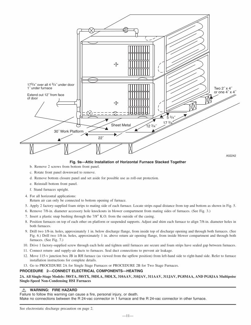
For attic installations on a platform (See Fig 9a):
1. Construct a platform from ¾″ (nominal plywood), extending out 30 inches from the front of each furnace.
2. Maintain all clearances to combustibles per the furnace Installation, Start-up and Operating Instructions.
3. Follow all additional building codes.
4. Long truss spans may require additional support along the bottom chord of the truss. Consult the truss manufacturer’s guidelines forengineering assistance.
5. Long rafter or attic joist spans may require additional support along the bottom of the rafter or joist. Consult local or regional building codesfor design and loading requirements.
For suspended installations (See Fig 9b. Not recommended for wood trusses unless approved by the truss manufacturer or other approvedengineering methods):
1. Furnaces may be suspended using two (2) pieces of 1 ½” x 1 ½” x ¼” thick cold rolled angle iron underneath the furnaces and four (4)3/8″ diameter threaded rods.
2. Allow for at least nine (9) inches in front of each door for door removal.
3. Each piece of angle iron must be secured to the bottom of each furnace with at least two (2) #8 x ¾″ sheet metal screws.
4. Maintain all clearances to combustibles per the furnace Installation, Start-up and Operating Instructions.
5. Unistrut or similar material may be used, provided that the furnaces do not sag in the middle or bend or twist at the support ends. The supportmaterial must be secured to the bottom of each furnace in a manner similar to securing angle iron to the furnace.
Refer to Fig. 3 and Table 2 for appearance and dimensional drawing of twinned furnaces and their connection locations.
1. Select 2 identical heating and airflow furnaces. (See Table 2.)
2. Remove outer door and blower access door.
3. Remove bottom closure panels from both furnaces. (See Fig. 4.)a. Lay furnaces on back or sides.
—10—
→
b. Remove 2 screws from bottom front panel.
c. Rotate front panel downward to remove.
d. Remove bottom closure panel and set aside for possible use as roll-out protection.
e. Reinstall bottom front panel.
f. Stand furnaces upright.
4. For all horizontal applications:Return air can only be connected to bottom opening of furnace.
5. Apply 2 factory-supplied foam strips to mating side of each furnace. Locate strips equal distance from top and bottom as shown in Fig. 5.
6. Remove 7/8-in. diameter accessory hole knockouts in blower compartment from mating sides of furnaces. (See Fig. 3.)
7. Insert a plastic snap bushing through the 7/8″ K.O. from the outside of the casing.
8. Position furnaces on top of each other on platform or suspended supports. Adjust and shim each furnace to align 7/8-in. diameter holes inboth furnaces.
9. Drill two 1/8-in. holes, approximately 1 in. below discharge flange, from inside top of discharge opening and through both furnaces. (SeeFig. 6.) Drill two 1/8-in. holes, approximately 1 in. above return air opening flange, from inside blower compartment and through bothfurnaces. (See Fig. 7.)
10. Drive 1 factory-supplied screw through each hole and tighten until furnaces are secure and foam strips have sealed gap between furnaces.
11. Connect return- and supply-air ducts to furnaces. Seal duct connections to prevent air leakage.
12. Move 115-v junction box JB in RH furnace (as viewed from the upflow position) from left-hand side to right-hand side. Refer to furnaceinstallation instructions for complete details.
13. Go to PROCEDURE 2A for Single Stage Furnaces or PROCEDURE 2B for Two Stage Furnaces.
PROCEDURE 2—CONNECT ELECTRICAL COMPONENTS—HEATING
2A. All Single-Stage Models: 58STA, 58STX, 58DLA, 58DLX, 310AAV, 310JAV, 311AAV, 311JAV, PG8MAA, AND PG8JAA MultipoiseSingle-Speed Non-Condensing HSI Furnaces
WARNING: FIRE HAZARDFailure to follow this warning can cause a fire, personal injury, or death.Make no connections between the R 24-vac connector in 1 furnace and the R 24-vac connector in other furnace.
See electrostatic discharge precaution on page 2.
Fig. 9a—Attic Installation of Horizontal Furnace Stacked Together
A02242
30˝ Work Platform
Two 2˝ x 4˝or one 4˝ x 4˝
Sheet Metal
22˝
12 3/4˝
5 3/4˝
173/4˝ over all 4 3/4˝ under door1˝ under furnace
Extend out 12˝ from faceof door
17 3/4˝
—11—

The twinning kit can be used for single-stage or 2-stage heating operation. There are 3 harness assemblies included in this kit. If the furnaces areside-by-side, only 2 harness assemblies are required. If the furnaces are installed back-to-back, all 3 harness assemblies included in the kit mustbe used.
1. Remove outer doors and blower access doors from both furnaces.
2. If furnaces are installed back-to-back in any orientation, the external Extension Harness must be used. The harness consists of:
a. 54 ½ inches of ½″ flexible steel conduit
b. (2) 90° conduit connectors
c. (1) 4 wire polarized wiring harness
d. (1) 2 wire polarized wiring harness
3. Install the Extension Harness as follows:
a. Remove lock nuts from the end of each conduit connector.
b. Route the end of the harness, labeled “twinning kit harness,” that mates to the TRK relay harness from the outside of the furnace throughthe 7/8″ knock-out in the casing to the blower compartment.
c. Route the end of the harness that mates to the 4-wire harness through the outside of the furnace through the 7/8″ knockout in the casingto the blower compartment.
d. Install the lock nuts on the 90° conduit connectors.
e. Install 2 kit-supplied straps approximately 18 inches from each end of harness.
Single-Stage Heat with Single-Stage Gas-Heat Thermostat (Field-Supplied)
NOTE: This application allows both furnaces to operate as 1 furnace in gas heat mode as determined by single-stage thermostat operation. Bothfurnaces operate in heating mode simultaneously. See furnace Installation, Start-Up, and Operating Instructions for further details on this heatingmode.
1. Install harness labeled “Main Furnace” with TKR on L/H Furnace:The Main Harness includes the TKR relay and Auxiliary Limit switch on the harness. The harness is also tagged ″Main Furnace″ near theends of the plug connector.
a. Secure relay of TKR harness assembly to LH furnace control mounting bracket using 2 factory-supplied screws. (See Fig. 10A.)
NOTE: See Fig. 13 for Single Stage furnace Twinning Kit wiring diagram.
b. Connect TKR white wire labeled W from TKR to LH furnace control thermostat connection W.
Fig. 9b—Suspended Installation for Horizontal Furnaces Stacked Together
A02202
3/8” Threaded Rod
See detail 9” minimum for door removal
Secure angle iron to bottom offurnace with at least (2) #8 x 3/4”sheet metal screws
11/2” x 11/2” x 11/4”Angle Iron
—12—

c. Connect TKR black wire labeled C from TKR to LH furnace control thermostat connection COM 24V.
d. Connect yellow wire labeled TEST to LH furnace control TEST/TWIN terminal.
e. If Extension Harness was used, connect 4-wire harness to Extension Harness.
NOTE: If Extension Harness will not plug in to L/H and R/H furnaces, extension harness is installed backward. Remove extension harness andre-install in correct orientation.
2. Install Auxillary Limit Switch (ALS-M) on L/H furnace:
a. Drill 1/8-in. hole in blower housing 12 in. below blower shelf. (See Fig. 11.)
b. Position ALS-M so reset button faces front of furnace.
c. Secure bracket to blower housing using a factory-supplied screw.
d. Disconnect red transformer wire from LH furnace control SEC-1 connection.
e. Connect red transformer wire connector to ALS-M wire connector PL7 labeled TRAN.
f. Connect orange ALS-M wire connector labeled DOOR SWITCH or SEC 1 to LH furnace control SEC-1 terminal.
g. If Extension Harness was used, connect 2-wire harness to Extension Harness
3. Install Secondary 4-wire harness on R/H furnace:
The Secondary Harness includes the Auxiliary Door Switch and Auxiliary Limit Switch. The harness is also tagged ″Secondary Furnace″ near theplug ends of the harness.
a. Connect red wire labeled R-Secondary to RH furnace control thermostat connection R.
b. Connect white wire labeled W-Secondary to RH furnace control thermostat connection W.
c. Connect black wire labeled C-Secondary to RH furnace control thermostat connection COM 24V.
d. Connect yellow wire labeled TEST SECONDARY from LH furnace control TEST terminal to RH furnace control TEST terminal.
e. If the furnaces are side-by-side, route loose ends of 4-wire harness from Secondary furnace to Main furnace through snap bushingspreviously installed between furnaces. (See Fig. 4.)
f. Connect Secondary 4-wire harness into 4-wire Main harness.
g. If Extension Harness was installed, connect 4-wire Secondary Harness to the Extension Harness.
4. Install Auxiliary Limit Switch, ALS-S on Secondary furnace:
a. Drill 1/8-in. hole in blower housing 12 in. below blower shelf. (See Fig. 11.)
b. Position ALS-S with terminals facing front of furnace.
c. Secure bracket to blower housing using factory-supplied screw.
Fig. 10A—TKR Relay Secured with Factory-Supplied Screws on Single-Stage Unit
A02233
TKR Relay-Secure w/2factory-supplied screws
—13—
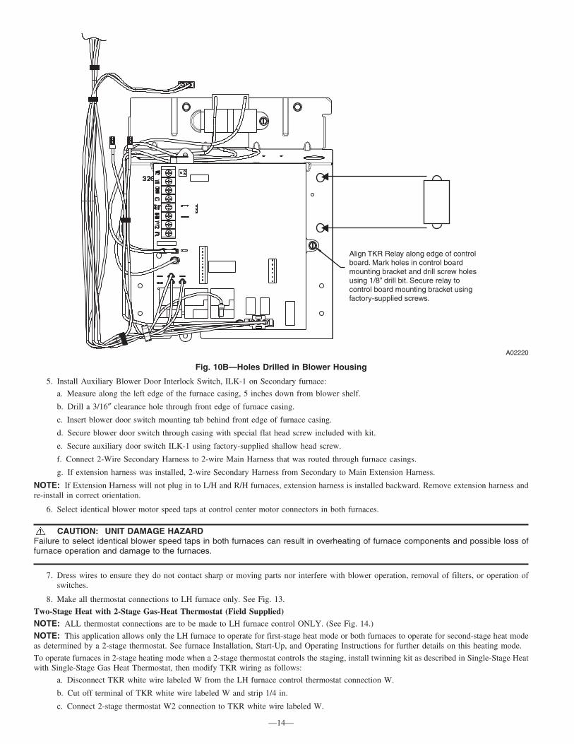
5. Install Auxiliary Blower Door Interlock Switch, ILK-1 on Secondary furnace:
a. Measure along the left edge of the furnace casing, 5 inches down from blower shelf.
b. Drill a 3/16″ clearance hole through front edge of furnace casing.
c. Insert blower door switch mounting tab behind front edge of furnace casing.
d. Secure blower door switch through casing with special flat head screw included with kit.
e. Secure auxiliary door switch ILK-1 using factory-supplied shallow head screw.
f. Connect 2-Wire Secondary Harness to 2-wire Main Harness that was routed through furnace casings.
g. If extension harness was installed, 2-wire Secondary Harness from Secondary to Main Extension Harness.
NOTE: If Extension Harness will not plug in to L/H and R/H furnaces, extension harness is installed backward. Remove extension harness andre-install in correct orientation.
6. Select identical blower motor speed taps at control center motor connectors in both furnaces.
CAUTION: UNIT DAMAGE HAZARDFailure to select identical blower speed taps in both furnaces can result in overheating of furnace components and possible loss offurnace operation and damage to the furnaces.
7. Dress wires to ensure they do not contact sharp or moving parts nor interfere with blower operation, removal of filters, or operation ofswitches.
8. Make all thermostat connections to LH furnace only. See Fig. 13.
Two-Stage Heat with 2-Stage Gas-Heat Thermostat (Field Supplied)
NOTE: ALL thermostat connections are to be made to LH furnace control ONLY. (See Fig. 14.)
NOTE: This application allows only the LH furnace to operate for first-stage heat mode or both furnaces to operate for second-stage heat modeas determined by a 2-stage thermostat. See furnace Installation, Start-Up, and Operating Instructions for further details on this heating mode.
To operate furnaces in 2-stage heating mode when a 2-stage thermostat controls the staging, install twinning kit as described in Single-Stage Heatwith Single-Stage Gas Heat Thermostat, then modify TKR wiring as follows:
a. Disconnect TKR white wire labeled W from the LH furnace control thermostat connection W.
b. Cut off terminal of TKR white wire labeled W and strip 1/4 in.
c. Connect 2-stage thermostat W2 connection to TKR white wire labeled W.
Fig. 10B—Holes Drilled in Blower Housing
A02220
Align TKR Relay along edge of controlboard. Mark holes in control board mounting bracket and drill screw holes using 1/8” drill bit. Secure relay to control board mounting bracket using factory-supplied screws.
—14—

CAUTION: UNIT DAMAGE HAZARDFailure to follow this caution could result in intermitted furnace operation and unit damage.Supply-air temperature will be uneven left-to-right when only main system is operating.
NOTE: ALL other 2-stage thermostat connections are to be made to LH furnace control ONLY. (See Fig. 14.)
2B. All Two-Stage Models: 58CTA, 58CTX, 312AAV, 312JAV Multipoise Two-Speed Non-Condensing HSI Furnaces with PSC Motors
WARNING: FIRE HAZARDFailure to follow this warning could result in fire, personal injury or death.Make no connections between the R 24-vac connector in 1 furnace and the R 24-vac connector in other furnace.
See electrostatic discharge precaution on page 4.
The twinning kit can be used for single-stage or 2-stage heating operation. There are 3 harness assemblies included in this kit. If the furnaces areside-by-side, only 2 harness assemblies are required. If the furnaces are installed back-to-back, all 3 harness assemblies included in the kit mustbe used.
1. Remove outer doors and blower access doors from both furnaces.
2. If furnaces are installed back-to-back in any orientation, the external Extension Harness must be used. The harness consists of:
a. 54 ½ inches of ½″ flexible steel conduit
b. (2) 90° conduit connectors
c. (2) 4 wire polarized wiring harness
d. (2) 2 wire polarized wiring harness
3. Install the Extension Harness as follows:
a. Remove lock nuts from the end of each conduit connector.
b. Route the end of the harness labeled “Twinning Kit Harness” that mates to the TKR relay harness from the outside of the furnace throughthe 7/8″ knock-out in the casing to the blower compartment.
c. Route the end of the harness that mates to the 4-wire harness through the outside of the furnace through the 7/8″ knockout in the casingto the blower compartment.
d. Install the lock nuts on the 90° conduit connectors.
Fig. 11—Auxiliary Door Switch
A02251
—15—
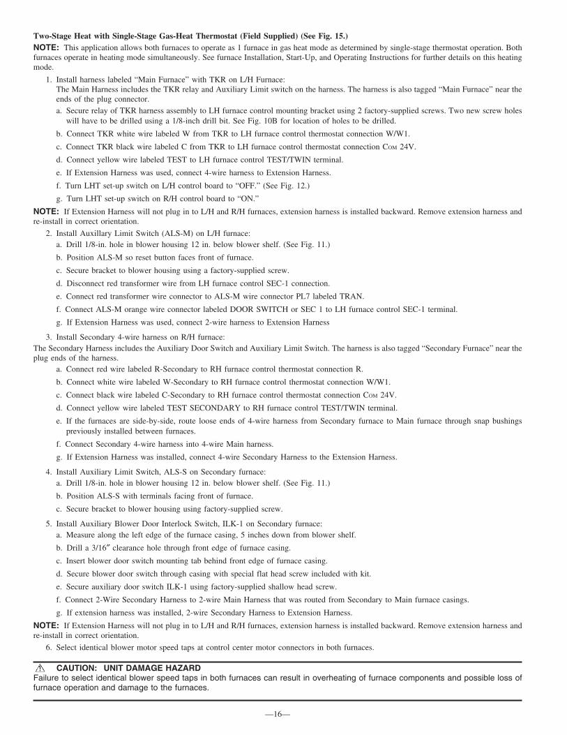
Two-Stage Heat with Single-Stage Gas-Heat Thermostat (Field Supplied) (See Fig. 15.)NOTE: This application allows both furnaces to operate as 1 furnace in gas heat mode as determined by single-stage thermostat operation. Bothfurnaces operate in heating mode simultaneously. See furnace Installation, Start-Up, and Operating Instructions for further details on this heatingmode.
1. Install harness labeled “Main Furnace” with TKR on L/H Furnace:The Main Harness includes the TKR relay and Auxiliary Limit switch on the harness. The harness is also tagged “Main Furnace” near theends of the plug connector.a. Secure relay of TKR harness assembly to LH furnace control mounting bracket using 2 factory-supplied screws. Two new screw holes
will have to be drilled using a 1/8-inch drill bit. See Fig. 10B for location of holes to be drilled.
b. Connect TKR white wire labeled W from TKR to LH furnace control thermostat connection W/W1.
c. Connect TKR black wire labeled C from TKR to LH furnace control thermostat connection COM 24V.
d. Connect yellow wire labeled TEST to LH furnace control TEST/TWIN terminal.
e. If Extension Harness was used, connect 4-wire harness to Extension Harness.
f. Turn LHT set-up switch on L/H control board to “OFF.” (See Fig. 12.)
g. Turn LHT set-up switch on R/H control board to “ON.”
NOTE: If Extension Harness will not plug in to L/H and R/H furnaces, extension harness is installed backward. Remove extension harness andre-install in correct orientation.
2. Install Auxillary Limit Switch (ALS-M) on L/H furnace:a. Drill 1/8-in. hole in blower housing 12 in. below blower shelf. (See Fig. 11.)
b. Position ALS-M so reset button faces front of furnace.
c. Secure bracket to blower housing using a factory-supplied screw.
d. Disconnect red transformer wire from LH furnace control SEC-1 connection.
e. Connect red transformer wire connector to ALS-M wire connector PL7 labeled TRAN.
f. Connect ALS-M orange wire connector labeled DOOR SWITCH or SEC 1 to LH furnace control SEC-1 terminal.
g. If Extension Harness was used, connect 2-wire harness to Extension Harness
3. Install Secondary 4-wire harness on R/H furnace:The Secondary Harness includes the Auxiliary Door Switch and Auxiliary Limit Switch. The harness is also tagged “Secondary Furnace” near theplug ends of the harness.
a. Connect red wire labeled R-Secondary to RH furnace control thermostat connection R.
b. Connect white wire labeled W-Secondary to RH furnace control thermostat connection W/W1.
c. Connect black wire labeled C-Secondary to RH furnace control thermostat connection COM 24V.
d. Connect yellow wire labeled TEST SECONDARY to RH furnace control TEST/TWIN terminal.
e. If the furnaces are side-by-side, route loose ends of 4-wire harness from Secondary furnace to Main furnace through snap bushingspreviously installed between furnaces.
f. Connect Secondary 4-wire harness into 4-wire Main harness.
g. If Extension Harness was installed, connect 4-wire Secondary Harness to the Extension Harness.
4. Install Auxiliary Limit Switch, ALS-S on Secondary furnace:a. Drill 1/8-in. hole in blower housing 12 in. below blower shelf. (See Fig. 11.)
b. Position ALS-S with terminals facing front of furnace.
c. Secure bracket to blower housing using factory-supplied screw.
5. Install Auxiliary Blower Door Interlock Switch, ILK-1 on Secondary furnace:a. Measure along the left edge of the furnace casing, 5 inches down from blower shelf.
b. Drill a 3/16″ clearance hole through front edge of furnace casing.
c. Insert blower door switch mounting tab behind front edge of furnace casing.
d. Secure blower door switch through casing with special flat head screw included with kit.
e. Secure auxiliary door switch ILK-1 using factory-supplied shallow head screw.
f. Connect 2-Wire Secondary Harness to 2-wire Main Harness that was routed from Secondary to Main furnace casings.
g. If extension harness was installed, 2-wire Secondary Harness to Extension Harness.
NOTE: If Extension Harness will not plug in to L/H and R/H furnaces, extension harness is installed backward. Remove extension harness andre-install in correct orientation.
6. Select identical blower motor speed taps at control center motor connectors in both furnaces.
CAUTION: UNIT DAMAGE HAZARDFailure to select identical blower speed taps in both furnaces can result in overheating of furnace components and possible loss offurnace operation and damage to the furnaces.
—16—
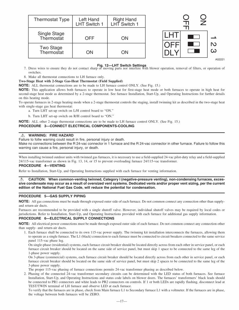
7. Dress wires to ensure they do not contact sharp or moving parts nor interfere with blower operation, removal of filters, or operation ofswitches.
8. Make all thermostat connections to LH furnace only.Two-Stage Heat with 2-Stage Gas-Heat Thermostat (Field Supplied)NOTE: ALL thermostat connections are to be made to LH furnace control ONLY. (See Fig. 15.)NOTE: This application allows both furnaces to operate in low heat for first-stage heat mode or both furnaces to operate in high heat forsecond-stage heat mode as determined by a 2-stage thermostat. See furnace Installation, Start-Up, and Operating Instructions for further detailson this heating mode.To operate furnaces in 2-stage heating mode when a 2-stage thermostat controls the staging, install twinning kit as described in the two-stage heatwith single-stage gas heat thermostat:
a. Turn LHT set-up switch on L/H control board to “ON.”
b. Turn LHT set-up switch on R/H control board to “ON.”
NOTE: ALL other 2-stage thermostat connections are to be made to LH furnace control ONLY. (See Fig. 15.)PROCEDURE 3—CONNECT ELECTRICAL COMPONENTS-COOLING
WARNING: FIRE HAZARDFailure to follw warning could result in fire, personal injury or death.Make no connections between the R 24-vac connector in 1 furnace and the R 24-vac connector in other furnace. Failure to follow thiswarning can cause a fire, personal injury, or death.
When installing twinned outdoor units with twinned gas furnaces, it is necessary to use a field-supplied 24-vac pilot-duty relay and a field-supplied24/115-vac transformer as shown in Fig. 13, 14, or 15 to prevent overloading furnace 24/115-vac transformer.PROCEDURE 4—VENTING
Refer to Installation, Start-Up, and Operating Instructions supplied with each furnace for venting information.
CAUTION: When common-venting twinned, Category I (negative-pressure venting), non-condensing furnaces, exces-sive condensate may occur as a result of oversized vent systems. Dedicated vents and/or proper vent sizing, per the currentedition of the National Fuel Gas Code, will reduce the potential for condensation.
PROCEDURE 5—GAS SUPPLY PIPING
NOTE: All gas connections must be made through exposed outer side of each furnace. Do not common connect any connection other than supply-and return-air ducts.Furnaces are recommended to be provided with a single shutoff valve. However, individual shutoff valves may be required by local codes orjurisdictions. Refer to Installation, Start-Up, and Operating Instructions provided with each furnace for additional gas supply information.PROCEDURE 6—ELECTRICAL SUPPLY CONNECTIONS
NOTE: All electrical power connections must be made through exposed outer side of each furnace. Do not common connect any connection otherthan supply- and return-air ducts.
1. Each furnace shall be connected to its own 115-vac power supply. The twinning kit installation interconnects the furnaces, allowing themto operate as a single furnace. The L1 (black) connection to each furnace must be connected to circuit breakers connected to the same servicepanel 115-vac phase leg.On single-phase (residential) systems, each furnace circuit breaker should be located directly across from each other in service panel, or eachfurnace circuit breaker should be located on the same side of service panel, but must skip 1 space to be connected to the same leg of the1-phase power supply.On 3-phase (commercial) systems, each furnace circuit breaker should be located directly across from each other in service panel, or eachfurnace circuit breaker should be located on the same side of service panel, but must skip 2 spaces to be connected to the same leg of the3-phase power supply.The proper 115-vac phasing of furnace connections permits 24-vac transformer phasing as described below.
2. Phasing of the connected 24-vac transformer secondary circuits can be determined with the LED status of both furnaces. See furnaceInstallation, Start-Up, and Operating Instructions and status code labels on blower doors. The furnaces’ transformers’ black leads shouldbe connected to PR1 connectors and white leads to PR2 connectors on controls. If 1 or both LEDs are rapidly flashing, disconnect lead atTEST/TWIN terminal of LH furnace and observe LED at each furnace.To verify that the furnaces are in phase, check from Main furnace L1 to Secondary furnace L1 with a voltmeter. If the furnaces are in phase,the voltage between both furnaces will be ZERO.
Fig. 12—LHT Switch Settings
A02221
LHTOFFDLY
OF
F
ON
1 2 3Thermostat Type Left Hand Right Hand
LHT Switch 1 LHT Switch 1
Single StageThermostat OFF ON
Two StageThermostat ON ON
—17—

IF:
a. Both LEDs are on continuously:System phasing is okay.
b. One or both LEDs are rapidly flashing:
(1.) Line voltage polarity is reversed
(2.) Reverse SEC-1 and SEC-2 in furnace with rapid flashing LED.
c. One LED is off, 1 LED is on continuously:
(1.) The 24-vac circuit is inoperative on furnace with LED light off.
(2.) Check transformers, auxiliary limits, and door switches in both furnaces and correct problem.
Fig. 13—Single Stage Furnace and A/C-Single Stage Thermostat
A02227
THERMOSTAT MAIN ( LH ) FURNACE
RELAY 1
PLCALS-M
PLA
NOTE #5
Y/Y2
G
W
R
COM
Y1
BLK
WHT
TEST/TWIN
TKR
BLU
SEC-2 SEC-1
TRANWHT
BLK
L2
NOTE #2
PR1
BLK
WHT
RED
YEL
PLB
SECONDARY ( RH ) FURNACE
Y/Y2
G
W
R
COM
Y1
TEST/TWIN
BLU
SEC-2 SEC-1
BLK
WHT
RED
YEL
PLB RED
TRANWHT
BLK
L2
NOTE #2
PR1
MAKE NO THERMOSTAT CONNECTIONS TO
SECONDARY OR RH FURNACE
1
2
ORN
BLURED
EXTENSION HARNESS(IF USED)
PLA
1
2
ORN
BLUILK-1 ALS-S
NOTE #1
ORN
NOTE #3
24 VAC
TRANSFORMER (FIELD SUPPLIED) NOTE #4
115 VACC Y
OUTDOOR UNITNO. 1
C Y
OUTDOOR UNITNO. 2
LEGEND: NOTES:
Y
G
W
R
COM
NOTE #3
NOTE #6
327893-101 REV. A
1. ALS-S and ILK-1 are located in the SECONDARY or RH furnace blower compartment.
2. Primary connections of transformer not shown; refer to furnace wire label.
3. When extension harness is not required PLA and PLB must be routed through holes in casings.
4. Transformer = 115 VAC primary / 24 VAC secondary / 40VA.5. Relays = 24 VAC coils / pilot duty / normally open.6. Y1 and DHUM terminal not available on "RED" LED control board.
NOTE #6
ALS-M MAIN AUX. LIMIT SW., OVERTEMP-MANUAL RESET, SPST - (N.C.)
ALS-S SECONDARY AUX. LIMIT SW., OVERTEMP-MANUAL RESET, SPST - (N.C.)
ILK-1 SECONDARY AUX. BLOWER DOOR INTERLOCK SWITCH, SPST - (N.O.)
PLA 2-CIRCUIT TWINNING KIT CONNECTORPLB 4 - CIRCUIT TWINNING KIT CONNECTORPLC 1 - CIRCUIT TWINNING KIT IN-LINE SPLICETEST/TWIN COMPONENT TEST & TWINNING TERMINALTKR TWINNING KIT RELAY, SPST - (N.O.)TRAN TRANSFORMER - 115VAC / 24VAC
(PART OF FURNACE)115 VOLT WIRINGTWINNING KIT EXTENSION HARNESS (REQUIRED)FIELD WIRINGFACTORY WIRING (TWINNING KIT)
FIELD INSTALLED AIR CONDITIONING WIRING (WHEN REQUIRED)SINGLE STAGE FURNACE & A/C-SINGLE STAGE THERMOSTAT
DHUM DHUM
4
1
3
2
4
1
3
2
FIELDSUPPLIED
RELAY
—18—

d. One or both LEDs are dim or flickering.Furnaces are on different phase legs. Disconnect TWIN/TEST lead. If both LEDs are on continuously when TWIN/TEST isdisconnected, furnace line voltage power supply is out of phase.
3. Reconnect lead at TWIN/TEST terminal of LH furnace and observe LED at each furnace. The LEDs will glow steady for proper phasing.
PROCEDURE 7—START-UP AND ADJUSTMENT
Refer to Installation, Start-Up, and Operating Instructions supplied with furnaces for detailed information.
1. Shut off all power and gas to both furnaces.
2. Position blower off delay switches on controls in BOTH furnaces to SAME desired gas heat blower off delay. (See Fig. 16 and 17.) Seefurnace Installation, Start-Up, and Operating Instructions for further details.
3. Attach twinning connection wiring label above the existing furnace wiring label on the inside of the L/H furnace blower access door. Usethe following labels for the following applications:
Fig. 14—Single Stage Furnaces and A/C-Two Stage Thermostat
A02228
THERMOSTAT
RELAY 1
PLCALS-M
PLARELAY 2
NOTE #5
Y1
Y/Y2
G
W
R
COMBLK
WHTTEST/TWIN
TKR
BLU
SEC-2 SEC-1
TRANWHT
BLK
L2
NOTE #2
PR1
BLK
WHT
RED
YEL
PLB
Y/Y2
G
W
R
COM
Y1
TEST/TWIN
BLU
SEC-2 SEC-1
BLK
WHT
RED
YEL
PLB RED
TRANWHT
BLK
L2
NOTE #2
PR1
MAKE NO THERMOSTAT CONNECTIONS TO
SECONDARY OR RH FURNACE
1
2
ORN
BLURED
EXTENSION HARNESS(IF USED)
PLA
1
2
ORN
BLUILK-1 ALS-S
NOTE #1
ORN
NOTE #3
24 VAC
TRANSFORMER (FIELD SUPPLIED) NOTE #4
115 VAC C Y
OUTDOOR UNITNO. 1
C Y
OUTDOOR UNITNO. 2
LEGEND:
1. ALS-S and ILK-1 are located in the SECONDARY or RH furnace blower compartment.
2. Primary connections of transformer not shown; refer to furnace wire label.
3. When extension harness is not required PLA and PLB must be routed through holes in casings.
4. Transformer = 115 VAC primary / 24 VAC secondary / 40VA.5. Relays = 24 VAC coils / pilot duty / normally open.6. Y1 and DHUM terminal not available on "RED" LED control board.
NOTES:
W2
Y1
G
W/W1
R
COM
Y/Y2NOTE #3
327892-101 REV. A
NOTE #6NOTE #6
DHUM DHUM
4
1
3
2
4
1
3
2
FIELD INSTALLED AIR CONDITIONING WIRING (WHEN REQUIRED) SINGLE STAGE FURNACE & A/C-TWO STAGE THERMOSTAT
ALS-M MAIN AUX. LIMIT SW., OVERTEMP-MANUAL RESET, SPST - (N.C.)
ALS-S SECONDARY AUX. LIMIT SW., OVERTEMP-MANUAL RESET, SPST - (N.C.)
ILK-1 SECONDARY AUX. BLOWER DOOR INTERLOCK SWITCH, SPST - (N.O.)
PLA 2-CIRCUIT TWINNING KIT CONNECTORPLB 4 - CIRCUIT TWINNING KIT CONNECTORPLC 1 - CIRCUIT TWINNING KIT IN-LINE SPLICETEST/TWIN COMPONENT TEST & TWINNING TERMINALTKR TWINNING KIT RELAY, SPST - (N.O.)TRAN TRANSFORMER - 115VAC / 24VAC
(PART OF FURNACE)115 VOLT WIRINGTWINNING KIT EXTENSION HARNESS (REQUIRED)FIELD WIRINGFACTORY WIRING (TWINNING KIT)
FIELD SUPPLIED RELAYS
MAIN ( LH ) FURNACE SECONDARY ( RH ) FURNACE
—19—
Single Stage furnaces with single-stage thermostat, 327893–101Single Stage furnaces with two-stage thermostat, 327892–101Two Stage furnaces with single-stage or 2-stage thermostat, 327891–101
4. Attach twinning reference label 327956–101 on outside of blower access door of RH furnace blower door.
5. Turn on power and gas to both furnaces.
6. Reinstall blower access doors on both furnaces.
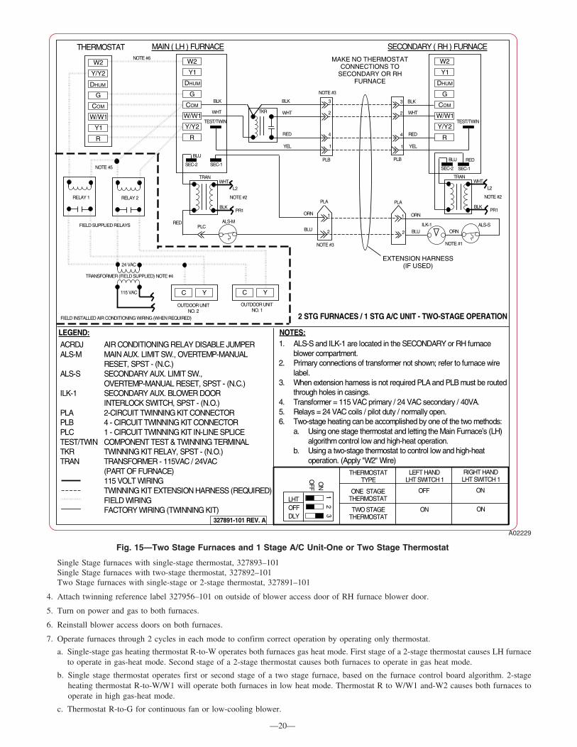
7. Operate furnaces through 2 cycles in each mode to confirm correct operation by operating only thermostat.
a. Single-stage gas heating thermostat R-to-W operates both furnaces gas heat mode. First stage of a 2-stage thermostat causes LH furnaceto operate in gas-heat mode. Second stage of a 2-stage thermostat causes both furnaces to operate in gas heat mode.
b. Single stage thermostat operates first or second stage of a two stage furnace, based on the furnace control board algorithm. 2-stageheating thermostat R-to-W/W1 will operate both furnaces in low heat mode. Thermostat R to W/W1 and-W2 causes both furnaces tooperate in high gas-heat mode.
c. Thermostat R-to-G for continuous fan or low-cooling blower.
Fig. 15—Two Stage Furnaces and 1 Stage A/C Unit-One or Two Stage Thermostat
A02229
THERMOSTAT
RELAY 1
PLCALS-M
PLARELAY 2
NOTE #5
W2
Y/Y2
G
W/W1
R
COM
Y1
BLK
WHT
TEST/TWIN
TKR
BLU
SEC-2 SEC-1
TRANWHT
BLK
L2
NOTE #2
PR1
BLK
WHT
RED
YEL
PLB
W2
Y/Y2
G
W/W1
R
COM
Y1
TEST/TWIN
BLU
SEC-2 SEC-1
4
1
3
2
BLK
WHT
RED
YEL
PLB RED
TRANWHT
BLK
L2
NOTE #2
PR1
MAKE NO THERMOSTAT CONNECTIONS TO
SECONDARY OR RH FURNACE
1
2
ORN
BLURED
EXTENSION HARNESS(IF USED)
PLA
1
2
ORN
BLUILK-1 ALS-S
NOTE #1
ORN
NOTE #3
24 VAC
TRANSFORMER (FIELD SUPPLIED) NOTE #4
115 VAC C Y
OUTDOOR UNITNO. 1
C Y
OUTDOOR UNITNO. 2
ACRDJ AIR CONDITIONING RELAY DISABLE JUMPERALS-M MAIN AUX. LIMIT SW., OVERTEMP-MANUAL
RESET, SPST - (N.C.)ALS-S SECONDARY AUX. LIMIT SW.,
OVERTEMP-MANUAL RESET, SPST - (N.C.)ILK-1 SECONDARY AUX. BLOWER DOOR
INTERLOCK SWITCH, SPST - (N.O.)PLA 2-CIRCUIT TWINNING KIT CONNECTORPLB 4 - CIRCUIT TWINNING KIT CONNECTORPLC 1 - CIRCUIT TWINNING KIT IN-LINE SPLICETEST/TWIN COMPONENT TEST & TWINNING TERMINALTKR TWINNING KIT RELAY, SPST - (N.O.)TRAN TRANSFORMER - 115VAC / 24VAC
(PART OF FURNACE)115 VOLT WIRINGTWINNING KIT EXTENSION HARNESS (REQUIRED)FIELD WIRINGFACTORY WIRING (TWINNING KIT)
LEGEND:1. ALS-S and ILK-1 are located in the SECONDARY or RH furnace
blower compartment.2. Primary connections of transformer not shown; refer to furnace wire
label.3. When extension harness is not required PLA and PLB must be routed
through holes in casings.4. Transformer = 115 VAC primary / 24 VAC secondary / 40VA.5. Relays = 24 VAC coils / pilot duty / normally open.6. Two-stage heating can be accomplished by one of the two methods:
a. Using one stage thermostat and letting the Main Furnace’s (LH)algorithm control low and high-heat operation.
b. Using a two-stage thermostat to control low and high-heat operation. (Apply "W2" Wire)
NOTES:
LHTOFFDLY
2O
NO
FF
THERMOSTATTYPE
LEFT HANDLHT SWITCH 1
RIGHT HANDLHT SWITCH 1
13 TWO STAGE
THERMOSTATON ON
W2
Y1
G
DHUM
W/W1
R
COM
Y/Y2
327891-101 REV. A
NOTE #3
NOTE #6
4
1
3
2
DHUM
2 STG FURNACES / 1 STG A/C UNIT - TWO-STAGE OPERATION
FIELD SUPPLIED RELAYS
FIELD INSTALLED AIR CONDITIONING WIRING (WHEN REQUIRED)
OFF ON
DHUM
MAIN ( LH ) FURNACE SECONDARY ( RH ) FURNACE
ONE STAGETHERMOSTAT
—20—
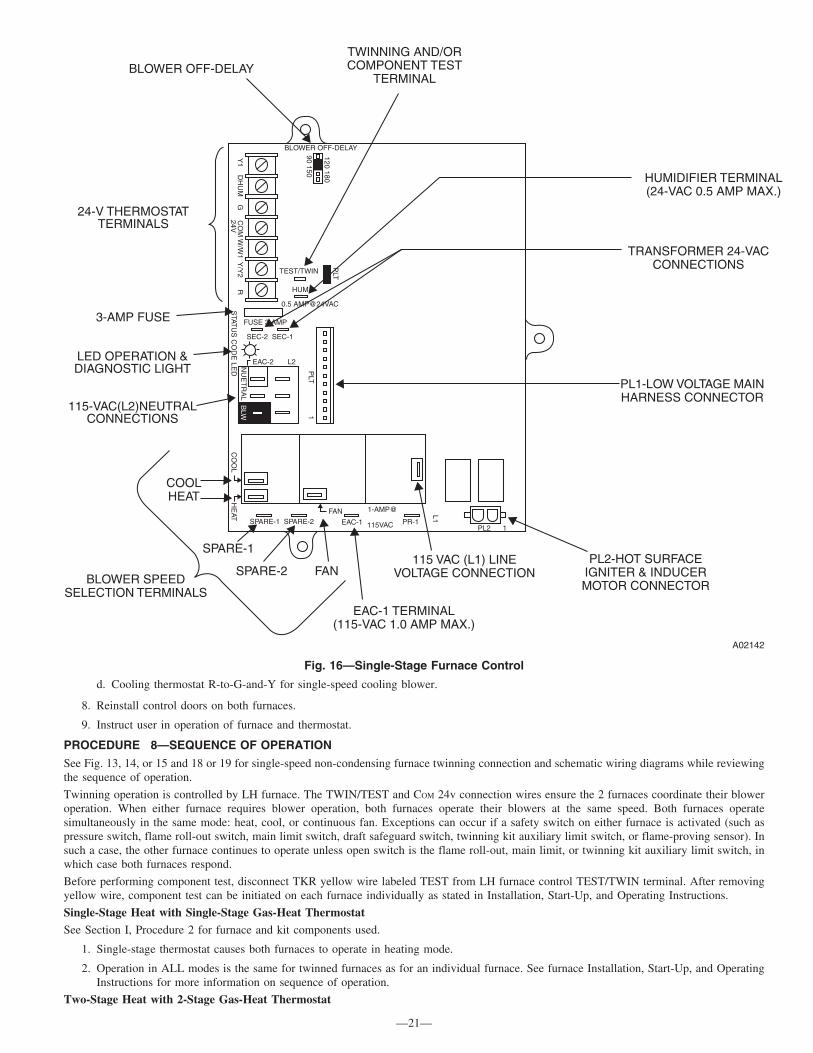
d. Cooling thermostat R-to-G-and-Y for single-speed cooling blower.
8. Reinstall control doors on both furnaces.
9. Instruct user in operation of furnace and thermostat.
PROCEDURE 8—SEQUENCE OF OPERATION
See Fig. 13, 14, or 15 and 18 or 19 for single-speed non-condensing furnace twinning connection and schematic wiring diagrams while reviewingthe sequence of operation.
Twinning operation is controlled by LH furnace. The TWIN/TEST and COM 24v connection wires ensure the 2 furnaces coordinate their bloweroperation. When either furnace requires blower operation, both furnaces operate their blowers at the same speed. Both furnaces operatesimultaneously in the same mode: heat, cool, or continuous fan. Exceptions can occur if a safety switch on either furnace is activated (such aspressure switch, flame roll-out switch, main limit switch, draft safeguard switch, twinning kit auxiliary limit switch, or flame-proving sensor). Insuch a case, the other furnace continues to operate unless open switch is the flame roll-out, main limit, or twinning kit auxiliary limit switch, inwhich case both furnaces respond.
Before performing component test, disconnect TKR yellow wire labeled TEST from LH furnace control TEST/TWIN terminal. After removingyellow wire, component test can be initiated on each furnace individually as stated in Installation, Start-Up, and Operating Instructions.
Single-Stage Heat with Single-Stage Gas-Heat Thermostat
See Section I, Procedure 2 for furnace and kit components used.
1. Single-stage thermostat causes both furnaces to operate in heating mode.
2. Operation in ALL modes is the same for twinned furnaces as for an individual furnace. See furnace Installation, Start-Up, and OperatingInstructions for more information on sequence of operation.
Two-Stage Heat with 2-Stage Gas-Heat Thermostat
Fig. 16—Single-Stage Furnace Control
A02142
BLW
NU
ET
RA
LS
TATU
S C
OD
E LE
D
SEC-2 SEC-1
EAC-2 L2
FUSE 3-AMP
0.5 AMP@24VAC
HUM
TEST/TWIN
Y1 D
HU
M G
CO
M W
/W1 Y
/Y2 R
24V
PLT
120 180
90 150
BLOWER OFF-DELAY
PLT
1
CO
OL H
EAT
SPARE-1 SPARE-2FAN
EAC-1
1-AMP@
115VAC PR-1
L1
PL2 1
24-V THERMOSTATTERMINALS
3-AMP FUSE
LED OPERATION &DIAGNOSTIC LIGHT
115-VAC(L2)NEUTRALCONNECTIONS
COOLHEAT
SPARE-1
SPARE-2 FANBLOWER SPEED
SELECTION TERMINALS
EAC-1 TERMINAL(115-VAC 1.0 AMP MAX.)
115 VAC (L1) LINEVOLTAGE CONNECTION
PL2-HOT SURFACEIGNITER & INDUCERMOTOR CONNECTOR
PL1-LOW VOLTAGE MAINHARNESS CONNECTOR
TRANSFORMER 24-VACCONNECTIONS
HUMIDIFIER TERMINAL(24-VAC 0.5 AMP MAX.)
TWINNING AND/ORCOMPONENT TEST
TERMINALBLOWER OFF-DELAY
—21—

See Section I, Procedure 2 for furnace and kit components used.
1. The 2-stage thermostat causes the furnaces to operate in first-stage heat (LH furnace operates in heat while RH furnace blower operates butRH furnace is not heating) or causes the furnaces to operate in second-stage heat (both furnaces operate in heat), depending on whether 1or 2 thermostat stages are calling for heat.
2. Operation in ALL modes is the same for twinned furnaces as for an individual furnace. See furnace Installation, Start-Up, and OperatingInstructions for more information on sequence of operation.
SECTION II: SINGLE-SPEED AND TWO-SPEED MULTIPOISE CONDENSING HSI FURNACE MODELSSINGLE STAGE SINGLE STAGE TWO-STAGE
Model Series Model Series Model Series58MCA 170 and later series 340MAV H and later series 58MTA 110 and later series58MXA 160 and later series 350MAV G and later series 58MTB 100 and later series58MCB 100 and later series PG9MAA E and later series 352MAV B and later series58MXB 100 and later series 340AAV A and later series 352AAV A and later series58MSA 140 and later series 350AAV A and later series34MAV E and later series PG9MAB A and later series
PROCEDURE 1—INSTALL FURNACES
NOTE: Multipoise units can be installed in UPFLOW, DOWNFLOW, or HORIZONTAL configurations.
A. Upflow, Downflow, Side-By-Side Configuration
Refer to Fig. 20 for appearance and dimensional drawing of twinned furnaces and their connection locations.
1. Select 2 identical heating and airflow furnaces. (See Table 3.)
2. Remove bottom closure panels from both furnaces. (See Fig. 22.)
a. Remove main and blower access doors.
b. Remove 2 screws from front filler panel.
c. Rotate front filler panel downward to remove.
Fig. 17—Two-Stage Furnace Control
A02017
LHTOFFDLY
ON
OF
FW2
BLW
24-V-THERMOSTAT TERMINALS
SETUP SWITCHESLOW-HEAT ONLY ANDBLOWER OFF-DELAY
TWINNING AND/ORCOMPONENT TEST
TERMINALACRDJ - AIR CONDITIONING
RELAY DISABLE JUMPER
TRANSFORMER 24-VACCONNECTIONS
PL1 - LOW VOLTAGE MAINHARNESS CONNECTOR
PL3 -ICM CONTROLHARNESS CONNECTOR
HUMIDIFIER TERMINAL(24-VAC 0.5 AMP MAX.)
3-AMP FUSE
LED OPERATION &DIAGNOSTIC LIGHT
115-VAC (L2) NEUTRALCONNECTIONS
PL2 - HOT SURFACEIGNITER & INDUCERMOTOR CONNECTOR
115-VAC (L1) LINEVOLTAGE CONNECTION
EAC-1 TERMINAL(115-VAC 1.0 AMP MAX.)
BLOWER SPEEDSELECTION TERMINALS
HI HEATLO HEAT
SPARE-1
SPARE-2 COOL
Y1DHUM
GCO
M24V
WW
1Y/Y2
R
TEST/TWIN
HUM
1 2 3
PLT
AC
RD
J
0.5-AMP024 VAC
FUSE 3-AMP
SEC-1 SEC-2
PL1
NEUTRAL-L2
1
EAC-2
BHT/CLRBHI/LOR
PL3 1
BLWR
COOL
SPARE-1 SPARE-2
1-AMP@115 VAC
EAC-1 PR-1
IDR
HSIR
IDM
IHI/LOR
PL21
HSI HI LO
STATUS
CODELED
HI HEATLO
HEAT
L1
—22—
→
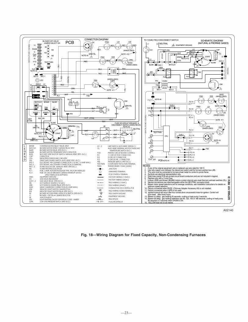
Fig. 18—Wiring Diagram for Fixed Capacity, Non-Condensing Furnaces
A02140
PCBY1
R
Y/Y2
W
C
HUM
EAC-2
JB
LEGEND
LS 1, 2 LIMIT SWITCH, AUTO-RESET, SPST(N.C.)OL AUTO-RESET INTERNAL MOTOR OVERLOAD
TEMPERATURE SWITCH (N.C.)PCB PRINTED CIRCUIT BOARD CONTROLPL1 11-CIRCUIT PCB CONNECTORPL2 2-CIRCUIT CONNECTORPL3 2-CIRCUIT HSI, CONNECTORPRS PRESSURE SWITCH, SPST-(N.O.)TEST/TWIN COMPONENT TEST & TWIN TERMINALTRAN TRANSFORMER-115VAC/24VAC
JUNCTION
UNMARKED TERMINAL
PCB CONTROL TERMINAL
FACTORY WIRING (115VAC)
FACTORY WIRING (24VAC)
FIELD WIRING (115VAC)
FIELD WIRING (24VAC)
CONDUCTOR ON CONTROL PCB
FIELD WIRING SCREW TERMINAL
FIELD EARTH GROUND
EQUIPMENT GROUND
FIELD SPLICE
PLUG RECEPTACLE
L1
L1
BLWR BHT/CLR
TO 115VAC FIELD DISCONNECT SWITCH
EQUIPMENT GROUND
SPARE-1
HEAT
FAN
COOL
STARTOL
HIMED HIMED LO
LO
BLWM
SCHEMATIC DIAGRAM(NATURAL & PROPANE GASES)
1 HSI
2PL3
CAP
L2
NOTES:
3275
60-1
01 R
EV.
D
om
NEUTRAL
L2
ILK
FU2 L1
ILK
RED
BLU
ORN
GRN
/YEL
TEST/TWIN
24V
FU1
LED
12
34
56
78
910
J1
BLOWER OFF-DELAY JUMPER SELECT OR
YEL
OL
START
BLKWHT
WHT (COM)
BLK BLK
WHTWHT
2 1
PL2
BLWM
CAP
SPARE 1 SPARE 2 EAC-1PR1
L1
SEC-2 SEC-1
EAC-2
180
150
120
90
PL1
BRN
BRN
RED (LO)
WHT(COM)
YEL
BLU(MED LO)
COM
G
DHUM
BLK (HI)
(MED HI)
115VACPR1
TRAN
24VAC
FRS1
FRS2
LGPS PRS
FSE
IDM
DSSBVSS
LS1 NOTE #10
(WHEN USED)
F U 1 NOTE #6
R
W
SEC-1 SEC-2
HUMGVR-2
PL1-1
CPU
Y1
G
C
GVR-1
OM
DHUM
Y/Y2
1. If any of the original equipment wire is replaced use wire rated for 105°C.2. Use only copper wire between the disconnect switch and the furnace junction box (JB).3. This wire must be connected to furnace sheet metal for control to prove flame.4. Symbols are electrical representation only.5. Solid lines inside PCB are printed circuit board conductors and are not included in legend.6. Replace only with a 3 amp fuse.7. Inducer (IDM) and blower (BLWM) motors contain internal auto-reset thermal overload switches (OL).8. Neutral connections are interchangeable within the NEUTRAL connector block.9. Blower motor speed selections are for average conditions, see installation instructions for details on
optimum speed selection.10. Factory connected when BVSS (Chimney Adapter Accessory Kit) is not installed.11. Factory connected when LGPS is not used.12. Ignition-lockout will occur after four consecutive unsuccessful trials-for-ignition. Control will
auto-reset after three hours.13. Blower-on delay: gas heating 25 seconds, cooling or heat pump 2 seconds.14. Blower-off delay: gas heating selections are 90, 120, 150 or 180 seconds, cooling or heat pump
90 seconds or 5 seconds when DHUM is ON.15. YELLOW lead not on all motors.
FAN
BFA
NR
TRA
N
FSE
LS1
RED
RED
BLU
RED WHT
BLK
BLK
WHT
IDM
HSI
WHT
BLK
21
PL3
FRS1
FRS2
BVSS
DSS
11
EAC-1HSIR
1
2PL2
IDR
FUSE OR CIRCUIT BREAKER &DISCONNECT SWITCH (WHEN REQ’D)
NOTE #2GRN/YEL
GRN/YEL
GND
NOTE #3
NOTE #6
WHT
NOTE #5
GV
GRN/YEL
RED
24V
NOTE #11
PRS(WHEN USED)
LGPS
YEL
(WHEN USED)
NOTE #10
L2
(WHEN USED)
NEU
TRA
L
NOTE #11
GV
NEU
TRA
L
NO
TE #
8
BFANR CONTINUOUS-FAN SELECT RELAY, SPDTBHT/CLR BLOWER MOTOR SPEED CHANGE RELAY, SPDTBLWR BLOWER MOTOR RELAY, SPST-(N.O.)BLWM BLOWER MOTOR, PERMANENT-SPLIT-CAPACITORBVSS BLOCKED VENT SHUTOFF SWITCH, MANUAL-RESET, SPST -(N.C.)CAP CAPACITORCPU MICROPROCESSOR AND CIRCUITRYDSS DRAFT SAFE GUARD SWITCH, AUTO-RESET, SPST -(N.C.)EAC-1 ELECTRONIC AIR CLEANER CONNECTION (115 VAC 1.0 AMP MAX.)EAC-2 ELECTRONIC AIR CLEANER CONNECTION (COMMON)FRS 1, 2 FLAME ROLLOUT SW. -MANUAL RESET, SPST-(N.C.)FSE FLAME-PROVING ELECTRODEFU 1 FUSE, 3 AMP, AUTOMOTIVE BLADE TYPE, FACTORY INSTALLEDFU 2 FUSE OR CIRCUIT BREAKER CURRENT INTERRUPT DEVICE
(FIELD INSTALLED & SUPPLIED)GND EQUIPMENT GROUNDGV GAS VALVE-REDUNDANTGVR 1, 2 GAS VALVE RELAY, DPST-(N.O.)HSI HOT SURFACE IGNITER (115 VAC)HSIR HOT SURFACE IGNITER RELAY, SPST-(N.O.)HUM 24VAC HUMIDIFIER CONNECTION (0.5 AMP. MAX.)IDM INDUCED DRAFT MOTOR, SHADED-POLEIDR INDUCED DRAFT MOTOR RELAY, SPST-(N.O.)ILK BLOWER ACCESS PANEL INTERLOCK SWITCH, SPST-(N.O.)J1 BLOWER - OFF DELAY JUMPER SELECTORJB JUNCTION BOXLED LIGHT-EMITTING DIODE FOR STATUS CODES - AMBERLGPS LOW GAS PRESSURE SWITCH, SPST-(N.O.)
NEUTRAL
BHT/CLR BFANR BLWR
CONNECTION DIAGRAM
COOL
HEAT
PL1-6
PL1-2
PL1-4
PL1-10
PL1-5
PL1-8
TEST/TWIN
PCB NOTE #5
BLW
PRINTED
CIRC
IUT BOA
RD
PRINTED
CIRC
IUT BOA
RD
PL1-3
PL1-9PL1-11
PL1-7
NOTE #15
NOTE #15
LS2
(WHEN USED)
LS2(WHEN USED)
RED RED RED
RED ORG ORG
—23—

Fig
.19
—W
irin
gD
iag
ram
for
Tw
o-S
tag
eN
on
-Co
nd
ensi
ng
Fu
rnac
esA
0215
9
GV
HIM
GR
N/Y
EL
CN
OTE
#3
BRN
BLU
BRN
GR
N/Y
EL
RED
RED
RED
NO
TE #
11FR
S1D
SS
BVS
S
LS1
(WH
EN U
SED
)
FRS2
NO
TE #
12
OR
NYE
L
HSI
L1N
OTE
#2
GN
D
NEU
TRAL
FU2
FUSE
OR
CIR
CUI
TBR
EAKE
R &
DIS
CO
NN
ECT
SWITC
H (W
HEN
REQ
'D)
BLK
ILK
PL5
JB
1 2
SEC-1
LEDSEC-2
FUSE 3-AMP
PLT
AC
RD
J
0.5 AMP@ 24 VAC
HUM
TEST/TWIN
ON
OFF
32
1
DLYOFFLHT
W/W
1D
HU
MG
24Vom
CW
2Y
/Y2
RY
1
TRAN
L1
PR-1
EAC-1
CA
P
OL
SPARE - 1
BLWR BHT/CLR BHI/LOR
COOL LO-HEAT
HI-HEAT
STA
RT
GR
N/Y
EL
BLW
M
NEUTRAL - L2 EAC-2
RE
D
BLU
OR
NYE
LBL
K
LOM
ED L
OM
EDHI
MED
HI
RED
BLU
WH
TW
HT
BRN
BRN
BLK
WH
T
BLK
WH
T
IHI/L
OR
HSI
R
IDR
LO HI HSI
GR
Y
CO
NN
ECTI
ON
DIA
GR
AM
BLK
1H
SI
2
IDM
1 23
HI
CO
M LO
S
CH
EMAT
IC D
IAG
RAM
(NAT
UR
AL G
AS &
PR
OPA
NE)
IDR
T
O 1
15VA
C F
IELD
-DIS
CO
NN
ECT
SWIT
CH
EQU
IPM
ENT
GR
OU
ND
12 3H
SIR
IHI/L
OR
PL2
L2
L2
CAP
OL
STAR
T
BLW
M
CO
M
LOM
ED L
OM
ED HI
ME
D H
I
LO H
EAT
SPA
RE-
2C
OO
LIN
G
SPAR
E-1
BHI/L
OR
BHT/
CLR
BLW
R
EAC
-2EA
C-1
TRAN
L2
L2
115V
AC
24VA
CSE
C 2
SEC
1
PR
1
FU1
NO
TE #
6
FRS
1D
SS
BVSS
FRS
2
(WH
EN U
SED
)
PL1-
8G
VR
-2H
UM R
AC
RPL
1-12
HP
SR
GV
LPS
NO
TE #
12
LGP
S(W
HEN
USE
D)
HPS HI
PL1-
2
PL1-
4
PL1-
3
PL1-
10
PL1-
5
W/W
1
CP
U
GVR
-1
TEST
/TW
IN
DH
UM
W2
Y/Y2
G Y1 CO
M 2
4VN
OTE
#3 CM
PL1-
1
LPS
(WH
EN
US
ED
)LG
PS
WH
T
FSE
PL1-
9
PL1-
11
PL1-
7
LEG
EN
D
AC
RA
IR C
ON
DITI
ON
ING
REL
AY, S
PST
(N.O
.)A
CRD
JA
IR C
ON
DITI
ON
ING
REL
AY D
ISA
BLE
JUM
PER
BHI/L
OR
BLO
WER
MO
TOR
SPEE
D C
HA
NG
E RE
LAY,
SPD
TBH
T/C
LRBL
OW
ER M
OTO
R SP
EED
CH
AN
GE
RELA
Y, S
PDT
BLW
RBL
OW
ER M
OTO
R RE
LAY,
SPS
T-(N
.O.)
BLW
MBL
OW
ER M
OTO
R, P
ERM
AN
ENT-
SPLI
T-C
APA
CITO
RBV
SSBL
OC
KED
VEN
T SH
UTO
FF S
WITC
H, M
AN
UAL-
RESE
T, SP
ST -(
N.C
.)C
AP
CA
PAC
ITO
RC
PUM
ICRO
PRO
CES
SOR
AN
D C
IRC
UITR
YD
HUM
DH
UM C
ON
NEC
TION
D
SSD
RAFT
SA
FE G
UARD
SW
ITCH
, AUT
O-R
ESET
, SPS
T -(
N.C
.)EA
C-1
ELEC
TRO
NIC
AIR
CLE
AN
ER C
ON
NEC
TION
(115
VA
C 1
.0 A
MP
MA
X.)
EAC
-2EL
ECTR
ON
IC A
IR C
LEA
NER
CO
NN
ECTIO
N (C
OM
MO
N)
FRS
1, 2
FLA
ME
ROLL
OU
T SW
. -M
AN
UAL
RESE
T, SP
ST-(
N.C
.)FS
EFL
AM
E-PR
OV
ING
ELE
CTR
OD
EFU
1FU
SE, 3
AM
P, A
UTO
MO
TIVE
BLA
DE
TYPE
, FA
CTO
RY IN
STA
LLED
FU2
FU
SE O
R C
IRC
UIT
BREA
KER
CU
RREN
T IN
TERR
UPT
DEV
ICE
(FIE
LD S
UPPL
IED
AN
D IN
STA
LLED
)G
ND
EQU
IPM
ENT
GRO
UND
GV
GA
S VA
LVE-
RED
UND
AN
T G
VR
1, 2
GA
S VA
LVE
RELA
Y, D
PST-
(N.O
.)H
PSH
IGH
-HEA
T PR
ESSU
RE S
WITC
H, S
PST
(N.O
.)H
PSR
HIG
H-H
EAT
PRES
SURE
SW
ITCH
REL
AY, S
PST
(N.C
.)H
SIH
OT
SURF
AC
E IG
NIT
ER (1
15VA
C)
HSI
RH
OT
SURF
AC
E IG
NIT
ER R
ELAY
, SPS
T (N
.O.)
HUM
24VA
C H
UM
IDIF
IER
CO
NN
ECTIO
N (0
.5 A
MP.
MA
X.)
IDM
IND
UC
ED D
RAFT
MO
TOR,
SH
AD
ED-P
OLE
IDR
IND
UC
ED D
RAFT
MO
TOR
RELA
Y, S
PST-
(N.O
.)IH
I/LO
RIN
DU
CER
MO
TOR
SPEE
D C
HA
NG
E RE
LAY,
SPD
TIL
KBL
OW
ER A
CC
ESS
PAN
EL IN
TERL
OC
K SW
ITCH
, SPS
T-(N
.O.)
JBJU
NC
TION
BO
XLE
DLI
GH
T-EM
ITTIN
G D
IOD
E FO
R ST
ATU
S C
OD
ES -
AM
BER
LGPS
LOW
GA
S PR
ESSU
RE S
WIT
CH
, SPS
T-(N
.O.)
LPS
LOW
-HEA
T PR
ESSU
RE S
WITC
H, S
PST
(N.O
.)LS
1, 2
LIM
IT S
WIT
CH
, AU
TO-R
ESET
, SPS
T (N
.C.)
OL
AU
TO-R
ESET
INTE
RNA
L M
OTO
R O
VER
LOA
D T
EMPE
RATU
RE S
WITC
H (N
.C.)
PCB
PRIN
TED
CIR
CU
IT BO
ARD
CO
NTR
OL
PL1
12-C
IRC
UIT
PCB
CO
NN
ECTO
RPL
23-
CIR
CU
IT PC
B H
SI &
IDM
CO
NN
ECTO
RPL
36-
CIR
CU
IT IC
M M
OTO
R C
ON
NEC
TOR
(NO
T SH
OW
N)
PL4
3-C
IRC
UIT
IDM
CO
NN
ECTO
R PL
52-
CIR
CU
IT H
SI C
ON
NEC
TOR
PLT
3-C
IRC
UIT
FAC
TORY
TES
T C
ON
NEC
TOR
TRA
NTR
AN
SFO
RMER
, 115
VAC
/24V
AC
TEST
/TW
INC
OM
PON
ENT
TEST
& T
WIN
NIN
G T
ERM
INA
L
JUN
CTIO
N
UNM
ARK
ED T
ERM
INA
L
PCB
CO
NTR
OL
TERM
INA
L
FAC
TORY
PO
WER
WIR
ING
(115
VAC
)
FAC
TORY
CO
NTR
OL
WIR
ING
(24V
AC
)
FIEL
D C
ON
TRO
L W
IRIN
G (1
15VA
C)
FIEL
D C
ON
TRO
L W
IRIN
G (2
4VA
C)
CO
ND
UC
TOR
ON
CO
NTR
OL
PCB
FIEL
D W
IRIN
G S
CRE
W T
ERM
INA
L
FIEL
D E
ART
H G
ROU
ND
EQUI
PMEN
T G
ROU
ND
FIEL
D S
PLIC
E
PLU
G R
ECEP
TAC
LE
PCB
PL1-
6
L1
NO
TE #
10
L2
PL4
PL5
WH
T
GR
N/Y
EL
WH
T
RED BLK
IDM
CO
MLO
PL4 13 2
H I
WH
T
RED BLK
PL2
IDM
NOTE #8
1 AMP @ 115 VAC
STA
TUS
CO
DE
FU1NOTE #6
PL1
1
SELE
CT
CH
ART
SWLO
-HT
ON
LYB
LOW
ERO
FF-D
ELA
Y
ON
OFF
1
ON
LYH
EAT
LOHEA
TN
OR
M2
390 SE
C.
ON
OFF
12
312
0SE
C.
ON
OFF
23
150
SEC
.
ON
OFF
23
180
SEC
.
HP
S
FAC
TOR
Y S
ETTI
NG
S
BLW
HI H
EAT
NO
TE #
11
NO
TE #
5
*
*
*
SPARE-2
FSE
RED
ACRDJ
3275
61-1
01 R
EV
. E
1.If
any
of th
e or
igin
al e
quip
men
t wire
is re
plac
ed u
se w
ire ra
ted
for 1
05∞C
.2.
Use
onl
y co
pper
wire
bet
wee
n th
e di
scon
nect
sw
itch
and
the
furn
ace
junc
tion
box
(JB
).3.
This
wire
mus
t be
conn
ecte
d to
furn
ace
shee
t met
al fo
r con
trol
to p
rove
flam
e.4.
Sym
bols
are
ele
ctric
al re
pres
enta
tion
only
.5.
Solid
line
s in
side
PC
B a
re p
rinte
d ci
rcui
t boa
rd c
ondu
ctor
s an
d ar
e no
t inc
lude
d in
the
lege
nd.
6.R
epla
ce o
nly
with
a 3
am
p fu
se.
7.B
low
er m
otor
(BLW
M) a
nd in
duce
r mot
or (I
DM
) con
tain
inte
rnal
aut
o-re
set t
herm
al o
verlo
ad s
witc
hes
(OL)
.8.
Neu
tral
con
nect
ions
are
inte
rcha
ngea
ble
with
in th
e N
EUTR
AL
conn
ecto
r blo
ck.
9.B
low
er m
otor
spe
ed s
elec
tions
are
for a
vera
ge c
ondi
tions
, see
inst
alla
tion
inst
ruct
ions
for o
ptim
um s
elec
tion.
10.F
acto
ry s
hipp
ed w
ith B
LUE
wire
(MED
LO
) if O
RA
NG
E w
ire n
ot p
rese
nt.
11.F
acto
ry c
onne
cted
whe
n B
VSS
(Chi
mne
y A
dapt
er K
it) is
not
inst
alle
d.12
.Fac
tory
con
nect
ed w
hen
LGPS
is n
ot u
sed.
13.I
gniti
on lo
ckou
t will
occ
ur a
fter f
our c
onse
cutiv
e un
succ
essf
ul tr
ials
-for-
igni
tion.
Con
trol
will
aut
o-re
set a
fter
thre
e ho
urs.
14.B
low
er-o
n de
lay:
gas
hig
h-he
at 2
5 se
cond
s, g
as lo
w-h
eat 4
5 se
cond
s, c
oolin
g or
hea
t pum
p 2
seco
nds.
15.B
low
er o
ff-de
lay:
gas
hea
ting
sele
ctio
ns a
re 9
0, 1
20, 1
50, 1
80 s
econ
ds, c
oolin
g or
hea
t pum
p 90
sec
onds
or
5 se
cond
s w
hen
DH
UM
is a
ctiv
e.
NO
TE
S:
PRINTED CIRCIUT BOARD
PRINTED CIRCIUT BOARD
RED
LS2
(WH
EN U
SED
)
LS2
(WH
EN
USE
D)
LS1
ILK
L1
—24—

d. Remove bottom closure panel and discard.
e. Reinstall front filler panel.
3. Apply 2 factory-supplied foam strips to mating side of each furnace. Locate strips equal distance from top and bottom as shown in Fig. 23.
4. Return air connections
a. For upflow applications:Bottom return air usage is required as part of any upflow return air configuration. If additional return air is to enter 1 side of each furnace,in addition to bottom return air, cut open 1 entire return-air opening in appropriate side of each furnace. (See Fig. 1.)
WARNING: UNIT DAMAGE AND FIRE HAZARDFailure to follow this warning could result in unit damager, fire, personal injury or death.DO NOT use the back of the furnace for return-air duct connections as limit cycling will occur.
b. For downflow applications:Return air can only be connected to bottom opening of furnace. A common return air plenum is required for proper auxiliary limit switchoperation. (See Fig. 2.)
5. For upflow applications
a. Position furnaces against each other on return-air plenum. Adjust and shim each furnace to align unused condensate drain line holes inlower section of both furnaces holes, which will be used for wire routing between furnaces. (See Fig. 29.)
b. Drill two 1/8-in. holes, approximately 1 in. below discharge air flange, from inside top of discharge opening and through both furnaces.(See Fig. 24.)
c. Drive 1 factory-supplied No. 6 X 3/4-in. LG screw through each hole and tighten until furnaces are secure and foam strips have sealedgap between furnaces.
Fig. 20—Dimensional Drawing for Twinned Single-Speed Condensing Furnaces (Upflow, Downflow)
A93537
17 5/16″
24 1/2″
27 1/2″TYP
27 5/8″
29 5/8″TYP
30 13/16″TYP
32 5/8″TYP
33 1/4″TYP
CONDENSATE DRAINTRAP LOCATION
7/8-IN. DIAACCESSORYPOWER ENTRY
7/8-IN. DIAPOWER CONN
26 15/16″
24 1/2″22 1/4″
2-IN. COMBUSTION-AIR CONN
1/2-IN. GAS CONN
2-IN. VENT CONN
1/2-IN. DIA THERMOSTATENTRY
22 11/16″
SIDE INLET
23 1/4″
11/4″1" E
INLET
11/16″E
INLET
11/16″
F 13/16″13/16″
OUTLET
A
AIRFLOW
OUTLET
26 15/16″28 1/2″
26 1/4″
22 13/16″19″ 13/16″
5/8″
39 7/8″
11/16″24 3/16″BOTTOM INLET
18 1/4″
22 11/16″
2-IN. COMBUSTION-AIR CONN
1/2-IN. GAS CONN
7/8-IN. DIAPOWER CONN
1/2-IN. DIATHERMOSTAT ENTRY
2-IN. VENT CONN
14 1/2″ SIDE INLET
OUTLET
AIRFLOW
D D
9 3/8″TYP
26 15/16″ TYP
SIDE INLET
CONDENSATEDRAIN LOCATION(USED FOR LH FURNACES AFTERSERIAL NO. 2894A00001)
30 1/2″
CONDENSATEDRAIN LOCATION(USED FOR RH FURNACES AFTERSERIAL NO. 2894A00001)
CONDENSATE DRAIN TRAP LOCATION
(USED FOR RH FURNACES BEFORESERIAL NO. 2894A00001)
(USED FOR LH FURNACES BEFORE SERIAL NO.
2894A00001)
26 1/4 TYP
→ Table 3—58MCA, 58MCB, 58MSA, 58MTB, 58MXA, 58MXB, 58MTA, 340AAV, 340MAV, 345MAV, 350AAV, 350MAV, 352AAV,352MAV, 490AAV, PG9MAA and PG9MAB Single-Speed Condensing Furnace Dimensions (In.)
INPUT HEATING SIZE(BTUH) NOMINAL COOLING SIZE A D E F
60,000 48,000 35 15-7/8 16 33-3/880,000* 48,000 35 15-7/8 16 33-3/880,000 60,000 42 19-3/8 19-1/2 40-3/8
100,000* 48,000 42 19-3/8 19-1/2 40-3/8100,000* 60,000 42 19-3/8 19-1/2 40-3/8120,000* 60,000 49 22-7/8 23 47-3/8
* Two speed furnace capacities and dimensions
—25—
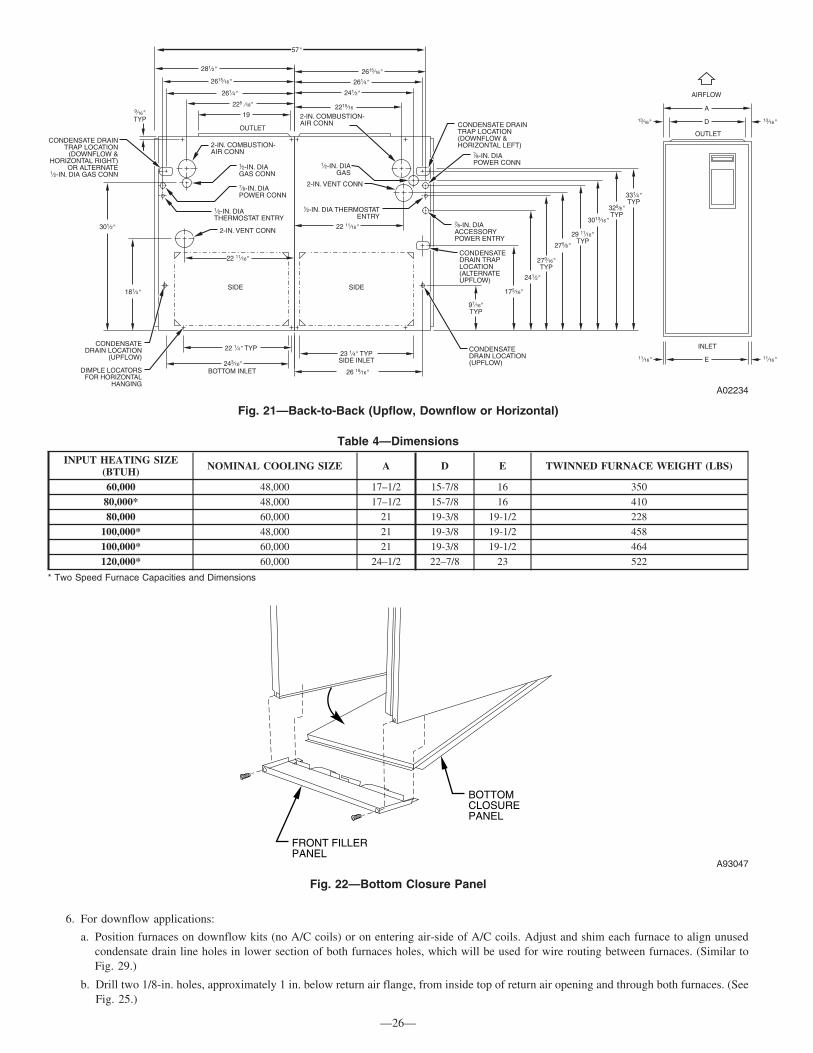
6. For downflow applications:
a. Position furnaces on downflow kits (no A/C coils) or on entering air-side of A/C coils. Adjust and shim each furnace to align unusedcondensate drain line holes in lower section of both furnaces holes, which will be used for wire routing between furnaces. (Similar toFig. 29.)
b. Drill two 1/8-in. holes, approximately 1 in. below return air flange, from inside top of return air opening and through both furnaces. (SeeFig. 25.)
Fig. 21—Back-to-Back (Upflow, Downflow or Horizontal)
A02234
Table 4—Dimensions
INPUT HEATING SIZE(BTUH) NOMINAL COOLING SIZE A D E TWINNED FURNACE WEIGHT (LBS)
60,000 48,000 17–1/2 15-7/8 16 350
80,000* 48,000 17–1/2 15-7/8 16 410
80,000 60,000 21 19-3/8 19-1/2 228
100,000* 48,000 21 19-3/8 19-1/2 458
100,000* 60,000 21 19-3/8 19-1/2 464
120,000* 60,000 24–1/2 22–7/8 23 522
* Two Speed Furnace Capacities and Dimensions
Fig. 22—Bottom Closure Panel
A93047
BOTTOMCLOSUREPANEL
FRONT FILLERPANEL
—26—

c. Drive 1 factory-supplied No. 6 X 3/4-in. LG screw through each hole and tighten until furnaces are secure and foam strips have sealedgap between furnaces.
7. Insert 1 snap bushing through each adjoining unused condensate drain line hole of each furnace.
8. Connect return- and supply-air ducts to furnaces. Seal duct connections to prevent air leakage.
9. 115-V junction boxes JB must be located on right side of right-hand furnace and left side of left-hand furnace. Relocate as necessary. (SeeFig. 29.)
10. Follow individual furnace installation instructions for upflow/downflow applications. This includes, but not limited to: condensate trap,condensate/inducer housing tubing, pressure switch tubing venting and electrical connections.
WARNING: UNIT DAMAGE AND FIRE HAZARDFailure to follow this warning could result in unit damage, fire, personal injury or death.DO NOT use the back of the furnace for return-air duct connections as limit cycling will occur.
B. Upflow/Downflow, Back-to-Back Configuration
Refer to Fig. 21 and Table 4 for appearance and dimensional drawing of twinned furnaces and their connection locations.
1. Select 2 identical heating and airflow furnaces. (See Table 4.)
2. Remove bottom closure panels from both furnaces. (See Fig. 22.)a. Remove main and blower access doors.
b. Remove 2 screws from front filler panel.
c. Rotate front filler panel downward to remove.
d. Remove bottom closure panel and discard.
e. Reinstall front filler panel.
3. Apply 2 factory-supplied foam strips to mating back of each furnace. Locate strips equal distance from top and bottom as shown in Fig.23. Trim off excess material.
Fig. 23—Location of Foam Strips and Hole to be Used for Twinning Kit Wire Routing
A02236
FOAMSTRIPS
UNUSED CONDENSATEDRAIN HOLE
FOR BACK-TO-BACKAPPLICATIONS, APPLYFOAM STRIPS AT THISHEIGHT, ALONG BACK OF FURNACE
Fig. 24—Attaching Furnaces Together
A93539
SCREW DISCHARGEOPENINGS TOGETHER
—27—

4. Return Air Connectionsa. For upflow applications:
Bottom return air usage is required as part of any upflow return air configuration. If additional return air is to enter 1 side of each furnace,in addition to bottom return air, cut open 1 entire return-air opening in appropriate side of each furnace. (See Fig. 1.)
WARNING: UNIT DAMAGE AND FIRE HAZARDFailure to follow this warning could result in unit damage, fire, personal injury or death.DO NOT use the back of the furnace for return-air duct connections in upflow position, as limit switch cycling will occur.
b. For downflow applications:Return air can only be connected to bottom opening of furnace. A common return air plenum is required for proper auxiliary limit switchoperation. (See Fig. 2.)
5. For upflow applicationsa. Position furnaces against each other on return-air plenum. (See Fig. 21.)
b. Drill two 1/8-in. holes, approximately 1 in. below discharge air flange, from inside top of discharge opening and through both furnaces.(See Fig. 25.)
c. Drive 1 factory-supplied No. 6 X 3/4-in. LG screw through each hole and tighten until furnaces are secure and foam strips have sealedgap between furnaces.
6. For downflow applicationsa. Position furnaces on downflow kits or plenum (no A/C coils) or on entering air-side of A/C coils. (See Fig. 21.)
b. Drill two 1/8-in. holes, approximately 1 in. below return air flange, from inside top of return air opening and through both furnaces. (SeeFig. 25.)
c. Drive 1 factory-supplied No. 6 X 3/4-in. LG screw through each hole and tighten until furnaces are secure and foam strips have sealedgap between furnaces.
7. Determine which side of furnace will be used to route external extension harness. If condensate drain hole is available, use it, otherwise,drill two 7/8-in holes in blower housing area, mid-point between blower deck and bottom of furnace.
NOTE: The external extension harness cannot be used on the same side of the furnace that the return air ducts connect to. Locate harness onopposite side of furnace where return air is used.
8. Connect return and supply-air ducts to furnaces. Seal duct connections to prevent air leakage.9. Follow individual furnace installation instructions for upflow/downflow applications. This includes, but not limited to: condensate trap,
condensate/inducer housing tubing, pressure switch tubing venting and electrical connections.C. Horizontal, Back-to-Back Configuration
When twinning furnaces in the horizontal position, consideration must be made to the type of building construction. Attic floors should beconstructed to support normal live and dead loads of the furnaces and the person(s) servicing them.Trusses, wood and metal are engineered for specific applications, and may not support the weight of two (2) furnaces suspended from the topchords or the bottom chords of the trusses. Long horizontals spans may flex or sag, resulting in damage to the building. Contact the trussmanufacturer for additional design and engineering assistance.
Fig. 25—Attaching Furnaces Together-Downflow
A02219
—28—
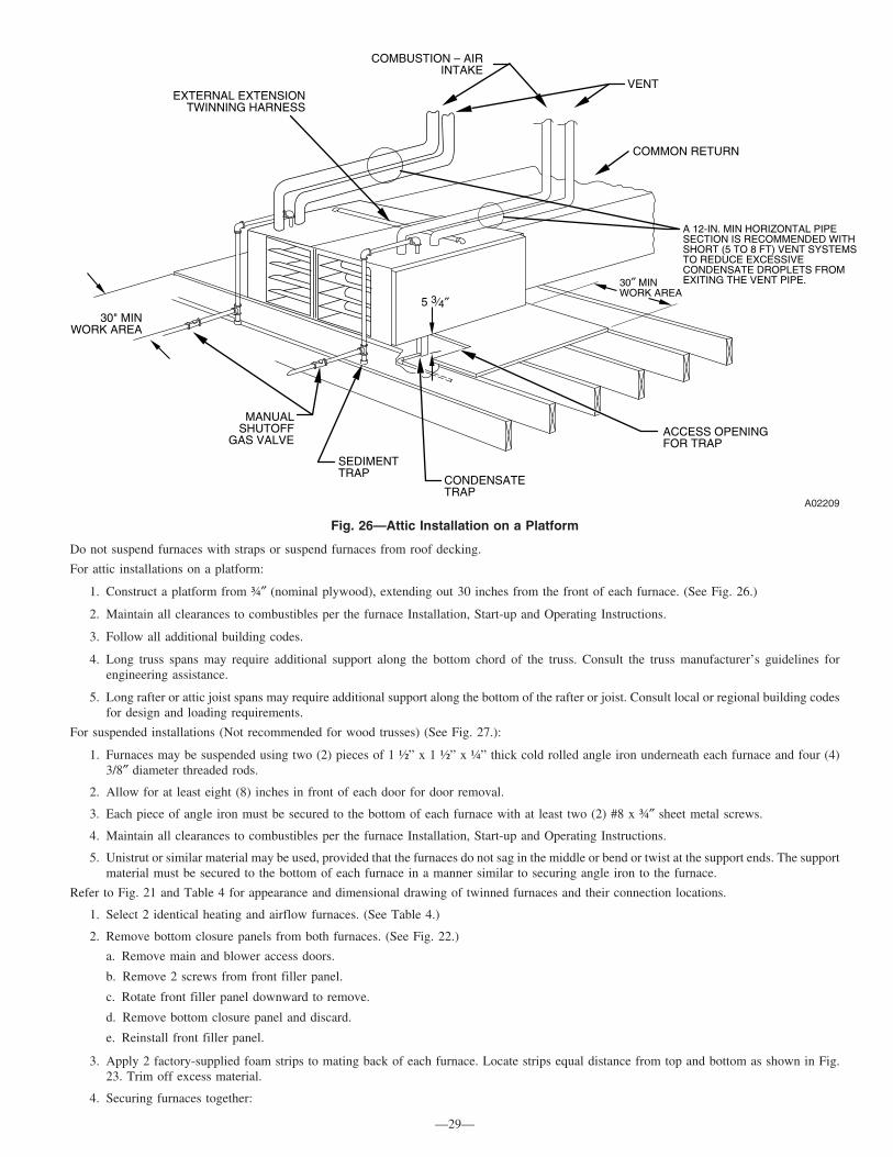
Do not suspend furnaces with straps or suspend furnaces from roof decking.
For attic installations on a platform:
1. Construct a platform from ¾″ (nominal plywood), extending out 30 inches from the front of each furnace. (See Fig. 26.)
2. Maintain all clearances to combustibles per the furnace Installation, Start-up and Operating Instructions.
3. Follow all additional building codes.
4. Long truss spans may require additional support along the bottom chord of the truss. Consult the truss manufacturer’s guidelines forengineering assistance.
5. Long rafter or attic joist spans may require additional support along the bottom of the rafter or joist. Consult local or regional building codesfor design and loading requirements.
For suspended installations (Not recommended for wood trusses) (See Fig. 27.):
1. Furnaces may be suspended using two (2) pieces of 1 ½” x 1 ½” x ¼” thick cold rolled angle iron underneath each furnace and four (4)3/8″ diameter threaded rods.
2. Allow for at least eight (8) inches in front of each door for door removal.
3. Each piece of angle iron must be secured to the bottom of each furnace with at least two (2) #8 x ¾″ sheet metal screws.
4. Maintain all clearances to combustibles per the furnace Installation, Start-up and Operating Instructions.
5. Unistrut or similar material may be used, provided that the furnaces do not sag in the middle or bend or twist at the support ends. The supportmaterial must be secured to the bottom of each furnace in a manner similar to securing angle iron to the furnace.
Refer to Fig. 21 and Table 4 for appearance and dimensional drawing of twinned furnaces and their connection locations.
1. Select 2 identical heating and airflow furnaces. (See Table 4.)
2. Remove bottom closure panels from both furnaces. (See Fig. 22.)
a. Remove main and blower access doors.
b. Remove 2 screws from front filler panel.
c. Rotate front filler panel downward to remove.
d. Remove bottom closure panel and discard.
e. Reinstall front filler panel.
3. Apply 2 factory-supplied foam strips to mating back of each furnace. Locate strips equal distance from top and bottom as shown in Fig.23. Trim off excess material.
4. Securing furnaces together:
Fig. 26—Attic Installation on a Platform
A02209
COMBUSTION – AIRINTAKE
VENT
MANUALSHUTOFF
GAS VALVE
SEDIMENTTRAP
CONDENSATETRAP
ACCESS OPENINGFOR TRAP
30″ MINWORK AREA
A 12-IN. MIN HORIZONTAL PIPESECTION IS RECOMMENDED WITHSHORT (5 TO 8 FT) VENT SYSTEMSTO REDUCE EXCESSIVECONDENSATE DROPLETS FROMEXITING THE VENT PIPE.
5 3⁄4″
COMMON RETURN
30" MINWORK AREA
EXTERNAL EXTENSIONTWINNING HARNESS
—29—

a. Lay furnaces back-to-back on a flat surface.
b. Similar to side-by-side installations (See Fig. 24.), drill two 1/8-in. holes, approximately 1 in. below discharge air flange, from insidetop of discharge opening and through both furnaces. Also drill two 1/8-in. holes, approximately 1 in. below return air flange, from insidetop of return air opening and through both furnaces.
c. Drive 1 factory-supplied No. 6 X 3/4-in. LG screw through each hole and tighten until furnaces are secure and foam strips have sealedgap between furnaces.
5. With furnaces laying in their side and back-to-back, determine which side will now be the top side to route external extension harness. Usethe unused condensate drain holes in blower housing area.
6. Connect return- and supply-air ducts to furnaces. Seal duct connections to prevent air leakage.
7. Follow individual furnace installation instructions for horizontal applications. This includes, but not limited to: condensate trap,condensate/inducer housing tubing, pressure switch tubing venting and electrical connections.
PROCEDURE 2—CONNECT ELECTRICAL COMPONENTS—HEATING
WARNING: FIRE HAZARDFailuie to follow this warning could result in fire, personal injury, or death.Make no connections between the R 24-vac connector in 1 furnace and the R 24-vac connector in other furnace.
See electrostatic discharge precaution on page 4.
NOTE: To determine referencing of Left Hand (LH) and Right Hand (RH) furnace:a. In the Side-by-Side, upflow and downflow applications, reference the furnaces from the front, as you would see them in the upflow application(See Fig. 29.) The LH furnace is the main furnace and the RH furnace is the secondary furnace.b. In the Back-to-Back, upflow, downflow and horizontal applications, reference the furnaces from the side of the external extension harness. TheLH furnace is the main furnace and the RH furnace is the secondary furnace, as you would see them in the upflow application (See Fig. 30.)
There are 3 harnesses included in this kit. If the furnaces are side-by-side, only 2 harnesses are required. If the furnaces are installed back-to-back,all 3 harnesses included in the kit must be used.
1. Remove outer doors and blower access doors from both furnaces.
2. If furnaces are installed back-to-back in any orientation, the External Extension Harness must be used. The harness consists of:
a. 54 ½ inches of ½″ flexible steel conduit
b. (2) 90° conduit connectors
c. (3) 4 wire polarized wiring harness
d. (3) 2 wire polarized wiring harness
Fig. 27—Suspended Installation of Furnaces
A02208
3/8" ROD, HEX NUT& WASHER
(B)(A)
(A)(B)
(B)
(A) ROD LOCATION USING DIMPLE LOCATORS ( SEE DIMENSIONAL DWG FOR LOCATIONS)
(B)(A)
(A) PREFERRED ROD LOCATION(B) ALTERNATE ROD LOCATION
11/2" ANGLEOR EQUIVALENT
(B)(B)(A)
3/8" NUT, BOLT& WASHERS
(A)(B)
USING (B) LOCATIONS13/16" MAX FROM BACK OF FURNACE
DRAIN
53/4"
USING (B) LOCATIONS4" TO 8" MAX
—30—

Install the harness as follows:a. Remove lock nuts from the end of each conduit connector.
b. Route the end of the harness that mates to the TKR relay harness of the LH furnace through the unused condensate trap hole in the casingof the blower compartment.
c. Route the end of the harness that mates to the 4-wire harness of the RH furnace through the unused condensate trap hole in the casingof the blower compartment.
d. Install the lock nuts on the 90° conduit connectors.
e. Install the two kit-supplied straps approximately 18 inches from each end of extension harness.
3. Fixed Capacity Furnace/Single-Stage Heat with Single-Stage Gas-Heat Thermostat (Field Supplied) OR Two-Stage Furnace withSingle or Two-Stage Gas-Heat Thermostat (Field-Supplied)
NOTE: This application of TKR allows both furnaces to operate as 1 furnace gas heat mode as determined by an individual thermostat.Install twinning kit relay (TKR):
a. Mount TKR assembly to underside of LH furnace control enclosure using 1 No. 6 sheet metal screw (factory supplied). Screw hole islocated to left of door switch near front edge of control. (See Fig. 28.)
NOTE: See Fig. 13 or 15 for twinning kit wiring.b. Route 3 loose wires (black, yellow, and white) from TKR assembly wire harness through T-STAT/HUM hole adjacent to door switch.
(See Fig. 28.)
c. Connect TKR white wire labeled W from TKR to LH furnace control thermostat connection W or W/W1.
d. Connect TKR black wire labeled C from TKR to LH furnace control thermostat connection COM 24V.
e. Connect yellow wire labeled TEST to LH furnace control TEST/TWIN terminal.
f. Route female four-pin connector end of TKR wires:
(1.) For Side-by-Side applications, see Fig. 20 and 29. Route female, four-pin connector through previously installed bushings in unusedcondensate drain holes, located on casing in blower compartment area. Connect to male four-pin connector of RH furnace.
(2.) For Back-to-Back applications, see Fig. 21 and 30. Connect the female, four pin connector to the male four pin connector of thepreviously installed External Extension Kit. Connect the female four pin connector of the External Extension Kit to the male fourpin connector of the RH furnace.
g. Route four wires through thermostat cable hole of RH furnace control box.
h. Connect TKR red wire labeled R-SECONDARY from TKR to RH furnace control thermostat connection R.
i. Connect TKR white wire labeled W-SECONDARY from TKR to RH furnace control thermostat connection W or W/W1.
j. Connect TKR black wire labeled C-SECONDARY from TKR to RH furnace control thermostat connection COM 24V.
k. Connect yellow wire labeled TEST SECONDARY from LH furnace control TEST/TWIN terminal to RH furnace control TEST/TWINterminal.
l. For Two-Stage Furnace Control Boards–In addition to the wiring of the twinning kit, the LHT switch and a single OR two-stagegas-heat thermostat must be configured to one of the two methods describe below:Two-Stage Heat with Single-Stage Gas-Heat Thermostat (allows the LH or Main Furnace’s algorithm control low and high-heatoperation)
(1.) Position LHT switch on Main or LH furnace control to OFF.
(2.) Position LHT switch on Secondary or RH furnace control to ON.
Two-Stage Heat with Two-Stage Gas-Heat Thermostat (allows a two-stage thermostat to control low and high-heat operation)Position LHT switch furnace controls in BOTH furnaces to ON
m. Proceed to #5 ″Install LH furnace auxiliary limit switch harness ALS-M″ to complete electrical connections.
Fig. 28—Twinning Kit Relay Mounted on Control Mounting Bracket for LH Furnace
A02226
—31—

4. Two-Stage Heating using Fixed Capacity Furnaces with Two-Stage Gas-Heat Thermostat (Field Supplied) (See Fig. 14.)NOTE: This modification allows LH furnace only to operate in heating mode for first-stage heat or both furnaces to operate in heating mode forsecond-stage heat as determined by a 2-stage thermostat. See furnace Installation, Start-Up, and Operating Instructions for further details on thisheating mode.To operate furnaces in 2-stage heating mode when a 2-stage thermostat controls the staging, install twinning kit as described above, then modifyTKR wiring as follows:
CAUTION: UNIT DAMAGE HAZARDFailure to follow this caution could result in intermitted furnace operation and unit damage.Supply-air temperature will be uneven left-to-right when only main system is operating.
Fig. 29—Twinning Kit Installed on Single-Speed and 2-Stage Condensing Furnaces(AFTER Serial No. 2894A00001)-Single-Speed Shown
A01377
AUXILIARY LIMITDOOR SWITCH(ILK-I)
POWER JUNCTION BOXRELOCATED HERE
SECONDARY AUXILIARYLIMIT SWITCH (ALS-S)
MAIN 24-VTRANSFORMER
MAIN BLOWER ACCESSPANEL DOOR SWITCH
SECONDARY 24-VTRANSFORMER
MAIN AUXILIARYLIMIT SWITCH
(ALS-M)
8″ TYP
TWINNING KITRELAY (TKR)
SECONDARY BLOWER ACCESSPANEL DOOR SWITCH
UNUSED CONDENSATEDRAIN LINE HOLESWITH SNAPBUSHING INSTALLED
Fig. 30—External Extension Harness (Back-to-Back Application)
A02225
Unused condensatedrain location
External Extension
—32—
→

NOTE: See Fig. 14.
a. Disconnect TKR white wire labeled W from LH furnace control thermostat connection W.
b. Cut terminal off TKR white wire labeled W and strip 1/4 in.
c. Connect 2-stage thermostat W2 connection to TKR white wire labeled W.
NOTE: ALL other 2-stage thermostat connections are to be made to LH furnace control center ONLY.
d. Proceed to #5 “Install LH furnace Auxiliary Limit Switch - Main ALS-M” harness to complete electrical connections.
5. Install LH furnace (main) auxiliary limit switch harness ALS-M.
NOTE: LH furnace ALS-M assembly DOES NOT include door switch.
a. Drill 1/8-in. hole in blower housing 8 in. below blower shelf as shown in Fig. 29.
b. Position ALS-M so reset button faces front of furnace.
c. Secure bracket to blower housing using factory-supplied No. 6 X 3/4-in. LG screw.
d. Disconnect red transformer wire from SEC-1 connection.
e. Connect removed red transformer wire to ALS-M wire connector labeled TRAN. Route through thermostat holes of control box.
f. Connect ALS-M connector labeled SEC 1 to LH furnace control SEC-1 terminal.
g. Route 2-wire ALS-M connector from LH furnace to RH furnace through unused condensate drain line hole with snap bushing.
6. Install RH furnace (SECONDARY) auxiliary door switch and harness (ALS-S/ILK-1).
NOTE: RH furnace ALS-S assembly HAS door switch included.
a. Install auxiliary limit switch (ALS-S).
(1.) Drill 1/8-in. hole in blower housing 8 in. below blower shelf as shown in Fig. 23.
(2.) Position ALS-S so terminals face front of furnace.
(3.) Secure bracket to blower housing using factory-supplied No. 6 X 3/4-in. LG screw.
b. Install auxiliary door switch (ILK-1).
(1.) Drill 7/32-in. hole in left side of RH furnace blower shelf for mounting door switch as shown in Fig. 29.
(2.) Secure ALS-S door switch (ILK-1) using factory-supplied flat screw No. 6 X 3/4-in. LG screw.
c. Connect RH furnace 2-wire ALS-S connector PL6 to LH furnace 2-wire ALS-M connector PL6 that was routed through furnace casings.
7. Select identical blower speed taps at blower motor connections on control center in both furnaces.
CAUTION: UNIT DAMAGE HAZARDFailure to select identical blower speed taps in both furnaces can result in overheating of furnace components and possible loss offurnace operation and damage to the furnace.
8. Dress wires to ensure they do not contact sharp edges or moving parts, nor interfere with blower operation, removal of filters, or operationof switches.
9. Make all thermostat connections to the LH furnace only.
PROCEDURE 3—CONNECT ELECTRICAL COMPONENTS—COOLING
WARNING: UNIT DAMAGE AND FIRE HAZARDFailure to follow this warning culd result in unit damage, fire, personal injury or death.Make no connections between the R 24-vac connector in 1 furnace and the R 24-vac connector in other furnace.
When installing twinned outdoor units with twinned gas furnaces, it is necessary to use a field-supplied 24-vac pilot-duty relay and a field-supplied24/115-vac transformer as shown in Fig. 13, 14, or 15 to prevent overloading furnace 24/115-vac transformer.
Fig. 31—LHT Switches
A02237
—33—

PROCEDURE 4—VENTING
Refer to Installation, Start-Up, and Operating Instructions supplied with each furnace for venting information. Each furnace must always beindividually vented. Do not common-vent or breach-vent condensing furnaces. For direct-vent installations, refer to Fig. 32, 33, 34, 35, or 36 forproper termination. It is important that vent terminations be made as shown to avoid recirculation of flue gases.
PROCEDURE 5—GAS SUPPLY PIPING
NOTE: All gas connections must be made through exposed outer side of each furnace. Do not common connect any connection other than supply-and return-air ducts.
Furnaces are recommended to be provided with a single shutoff valve. However, individual shutoff valves may be required by local codes orjurisdictions. Refer to Installation, Start-Up, and Operating Instructions provided with each furnace for additional gas supply information.
PROCEDURE 6—CONDENSATE DRAIN CONNECTIONS
The condensate trap is factory installed in blower shelf and factory connected for UPFLOW applications. Install condensate trap extension drainsuch that field drain connections are on the left side for LH (MAIN) furnace and on right side for RH (SECONDARY) furnace. (See Fig. 29.)
The condensate trap must be relocated for downflow and horizontal applications.
See furnace Installation, Start-Up, and Operating Instructions for details on attaching field drain for downflow and horizontal applications.
PROCEDURE 7—ELECTRICAL SUPPLY CONNECTIONS
NOTE: All electrical power connections must be made through exposed outer side of each furnace. Do not common connect any connection otherthan supply- and return-air ducts.
1. Each furnace shall be connected to its own 115-vac power supply. The twinning kit installation interconnects the furnaces, allowing themto operate as a single furnace. The L1 (black) connection to each furnace must be connected to circuit breakers connected to the same servicepanel 115-vac phase leg.On single-phase (residential) systems, each furnace circuit breaker should be located directly across from each other in service panel, oreach furnace circuit breaker should be located on the same side of service panel, but must skip 1 space to be connected to the same leg ofthe 1-phase power supply.On 3-phase(commercial) systems, each furnace circuit breaker should be located directly across from each other in service panel, or eachfurnace circuit breaker should be located on the same side of service panel, but must skip 2 spaces to be connected to the same leg of the3-phase power supply.The proper 115-vac phasing of furnace connections permits 24-vac transformer phasing as described below.
2. Phasing of the connected 24-vac transformer secondary circuits can be determined with the LED status of both furnaces. See furnaceInstallation, Start-Up, and Operating Instructions and status code label on blower access panel or main furnace door. The furnaces’transformers’ black leads should be connected to PR1 connectors and white leads to PR2 connectors on controls. If 1 or both LEDs arerapidly flashing, disconnect lead at TEST/TWIN terminal of LH furnace and observe LED at each furnace.
IF:
a. Both LEDs are on continuously:System phasing is okay.
b. One or both LEDs are rapidly flashing:
(1.) Line voltage polarity is reversed.
(2.) Reverse SEC-1 and SEC-2 in furnace with rapid flashing LED.
c. One LED is off, 1 LED is on continuously:
(1.) The 24-vac circuit is inoperative on furnace with LED light off.
(2.) Check transformers, auxiliary limits, and door switches in both furnaces and correct problem.
3. Reconnect lead at TWIN/TEST terminal of LH furnace and observe LED at each furnace. The LEDs will glow steady for proper phasing.
PROCEDURE 8—START-UP AND ADJUSTMENT
NOTE: Refer to Installation, Start-Up, and Operating Instructions supplied with furnace for detailed information.
1. Shut off all power and gas to both furnaces.
Fig. 32—Rooftop Termination (Dimension “A” is Touching or 2-in. Maximum Separation)
A96128
A
—34—

2. Position blower off delay switches on controls in BOTH furnaces to the SAME desired blower off delay in heating. See furnace Installation,Start-Up, and Operating Instruction for further details.
3. Attach twinning connection wiring label above the existing furnace wiring label on the inside of the L/H furnace blower access door. Usethe following labels for the following applications:Single Stage furnaces with single stage thermostat, 327893–101Single Stage furnaces with two-stage thermostat, 327892–101Two Stage furnaces with single stage or 2–stage thermostat, 327891–101
Fig. 33—Concentric Vent and Combustion-Air Roof Termination (Dimension “A” is Touching or 2-in. Maximum Separation)
A93056
COMBUSTIONAIR
VENTVENT
A
Fig. 34—Concentric Vent and Combustion-Air Side Termination (Dimension “A” is Touching or 2-in. Maximum Separation)
A93057
COMBUSTION AIR
VENT
A
VENT
1″ MAXIMUM(TYP)
Fig. 35—Sidewall Termination of 12 in. or Less (Dimension “A” is Touching or 2-in. Maximum Separation)
A96129
A
COMBUSTION AIR
COMBUSTION AIR
VENT
—35—

4. Attach twinning reference label 327956-101 on the outside of blower access door of RH furnace
5. Manually close the blower switch.
6. Turn on power and gas to furnaces.
7. Using appropriate section below, operate furnaces through 2 cycles in each mode to confirm correct operation by operating only thethermostat.
a. Single- or 2-stage gas heating thermostat R-to-W/W1 for low-gas heat. Single-stage thermostat with adaptive heating mode causesfurnace to operate in low-gas-heat mode for up to 16 minutes, and then furnace automatically switches to high-gas heat. First stage ofa 2-stage thermostat without adaptive heating mode causes furnace to operate in low-gas-heat mode indefinitely.
b. First and second-stage of 2-stage heating thermostat R-to-W/W1-and-W2 for high-gas-heat.
c. Thermostat R-to-G for continuous fan or 2-stage cooling low-cool blower.
d. Cooling thermostat R-to-G-and-Y/Y2 for single-speed cooling blower or for 2-stage cooling high-cool blower.
8. Reinstall control doors on both furnaces.
9. Instruct user in operation of furnaces and thermostat.
PROCEDURE 9—SEQUENCE OF OPERATION
See Fig. 13, 14, or 15 and 37 or 38 for condensing furnace twinning connection and schematic wiring diagrams while reviewing sequence ofoperation.
Twinning operation is controlled by LH or MAIN furnace. The TEST/TWIN connection wire ensures the 2 furnaces coordinate their bloweroperation. When either furnace requires blower operation, both furnace blowers operate at same speed. Both furnaces operate simultaneously inthe same mode: heat, cool, or continuous fan. Exceptions can occur if a safety switch on either furnace is opened by a problem (such as pressureswitch, flame roll-out switch, main limit switch, twinning kit auxiliary limit switch, or flame-proving sensor). In such a case, the other furnacecontinues to operate unless open switch is the flame roll-out, main limit, or twinning kit auxiliary limit switch, in which case both furnaces respond.
Before performing component test, disconnect TKR yellow wire labeled TEST from LH furnace control center TEST/TWIN terminal. Afterremoving yellow wire, component test can be initiated on each furnace individually as stated in Installation, Start-Up, and Operating Instructions.
A. Fixed Capacity Furnaces
SINGLE-STAGE HEAT, SINGLE STAGE FURNACES WITH SINGLE-STAGE GAS-HEAT THERMOSTAT
Operation in all modes (sequence of operation) is the same for twinned furnaces as for an individual furnace. See furnace Installation, Start-Up,and Operating Instructions for more information on the sequence of operation.
TWO-STAGE HEAT, SINGLE STAGE FURNACES WITH 2-STAGE GAS-HEAT THERMOSTAT
1. The two-stage thermostat determines if furnaces are operating in first-stage heat (LH furnace operates in heat while RH furnace bloweroperates but RH furnace is not heating) or if furnaces are operating in second-stage heat (both furnaces operate in heat), depending on howmany thermostat stages are calling for heat. If two-stage cooling is used, Y1 from the thermostat will initiate both furnace blowers to thecooling speed and the first A/C unit. Y2 from the thermostat will go directly to the outdoor unit and initiate the second A/C unit.
2. Operation in all modes (sequence of operation) is the same for twinned furnaces as for an individual furnace. See furnace Installation,Start-Up, and Operating Instructions for more information on sequence of operation.
TWO-STAGE HEAT, TWO STAGE FURNACES WITH SINGLE-STAGE GAS-HEAT THERMOSTAT
NOTE: See Section 2, Procedure 2 - Electrical Connections, Step 3 for control board wiring and LHT switch setup.
1. LH furnace control determines whether furnaces are both operating in low-gas heat or high-gas heat, depending on the control’s adaptivegas heating mode when the R-to-W/W1 circuit is closed in LH furnace.
Fig. 36—Sidewall Termination of More Than 12 in. (Dimension “A” is Touching or 2-in. Maximum Separation)
A96130
COMBUSTION AIRCOMBUSTION AIR
VENT
A
—36—

Fig. 37—Fixed Capacity Condensing Furnace Wiring Diagram
A02157
PCB
TRA
N
FRS
NOTE #11
LS
PRS(WHEN USED)
LGPS
FUSED OR CIRCUIT BREAKERDISCONNECT SWITCH (WHEN REQ’D)
NOTE #2JB
L1
L1
BLWR HI/LO
TO 115VAC FIELD DISCONNECTNOTE #2
EQUIPMENT GROUND
SPARE-1
HEAT
FAN
COOL
HSIREAC-1
STARTOL
HIMED HIMED LO
LO
BLWM
SCHEMATIC DIAGRAM(NATURAL GAS & PROPANE)
1 1 HSI
2PL32PL2
115VACPR1
TRAN24VAC
M
IDR
TEST/TWIN
F U 1 NOTE #6
IDMOL
AUX
CAP - 2
CAP-1
L2
FRS LS
LGPS (WHEN USED)
NOTE #11PRS
FSE9
1
5
CPU
PCB
Y1
G
C
R
W
SEC-1
GVR-1
NOTES:
326796-101 REV. A
OM
10
4
6
2
PL42
3
1
NEUTRAL
ILK
FU2L1
ILK
GND
RED
BLU
ORN
WHT
RED RED
ORN
RED
REDGRN/YEL
YEL
BLU
BLU
RED WHT
BLK
LED 1
12
34
56
78
910
BLOWER OFF DELAY JUMPER SELECT
YEL
OL
START
BLK
WHT
WHT
BRN
IDM
BRN
CAP -2
AUX
OL
M
HSIWHT
BLK
BLKWHT
WHT (COM)
BLK BLK
WHTWHT
2 1
PL2
WHT
BLKBLK
BLWM
CAP -1
SPARE 1 SPARE 2 EAC-1PR1
SEC-2 SEC-1
EAC-2
SEC-2
8
7
3
PL1
21
PL3
3
2
1
PL4
BRN
BRN
RED (LO)
WHT(COM)
YEL
BLU(MED LO)
COM
HUMGVR-2
DHUM
Y/Y2
(MED HI)
FAN
11 WHT
PL1
11
L2
GRN/YEL
GRN/YEL
GRN/YEL
GND
NOTE #3
GVM
C
NOTE #3
GVM
CGRN/YEL
GRN/YEL
FSE
NOTE #10
WHT
Y1
R
Y/Y2
W
C
HUM
om
TEST/TWIN
24V
FU1
J1
180
150
120
90
G
DHUM
NOTE #6
EAC-2 L2
NEU
TRA
L
NO
TE #
8
BLW
L1FAN
BHT/CLR BFANR BLWRCOOL
HEAT
BLK (HI)
LEGEND
BFANR CONTINUOUS-FAN SELECT RELAY, SPDTBHT/CLR BLOWER MOTOR SPEED CHANGE RELAY, SPDTBLWR BLOWER MOTOR RELAY, SPST-(N.O.)BLWM BLOWER MOTOR, PERMANENT-SPLIT-CAPACITORCAP 1, 2 CAPACITORCPU MICROPROCESSOR AND CIRCUITRYEAC-1 ELECTRONIC AIR CLEANER CONNECTION (115 VAC 1.0 AMP MAX.)EAC-2 ELECTRONIC AIR CLEANER CONNECTION (COMMON)FRS FLAME ROLLOUT SW. -MANUAL RESET, SPST-(N.C.)FSE FLAME-PROVING ELECTRODEFU 1 FUSE, 3 AMP, AUTOMOTIVE BLADE TYPE, FACTORY INSTALLEDFU 2 FUSE OR CIRCUIT BREAKER CURRENT INTERRUPT DEVICE
(FIELD INSTALLED & SUPPLIED)GND EQUIPMENT GROUNDGV GAS VALVE-REDUNDANTGVR 1, 2 GAS VALVE RELAY, DPST-(N.O.)HSI HOT SURFACE IGNITER (115 VAC)HSIR HOT SURFACE IGNITER RELAY, SPST-(N.O.)HUM 24VAC HUMIDIFIER CONNECTION (0.5 AMP. MAX.)IDM INDUCED DRAFT MOTOR, PSCIDR INDUCED DRAFT MOTOR RELAY, SPST-(N.O.)ILK BLOWER ACCESS PANEL INTERLOCK SWITCH, SPST-(N.O.)J1 BLOWER - OFF DELAY JUMPER SELECTORJB JUNCTION BOXLED LIGHT-EMITTING DIODE FOR STATUS CODES - AMBERLGPS LOW GAS PRESSURE SWITCH, SPST-(N.O.)LS LIMIT SWITCH, AUTO-RESET, SPST (N.C.)
OL AUTO-RESET INTERNAL MOTOR OVERLOADTEMPERATURE SWITCH (N.C.)
PCB PRINTED CIRCUIT BOARD CONTROLPL1 11-CIRCUIT PCB CONNECTORPL2 2-CIRCUIT CONNECTORPL3 2-CIRCUIT HSI, CONNECTORPL4 3-CIRCUIT IDM EXTENSION CONNECTORPRS PRESSURE SWITCH, SPST-(N.O.)TEST/TWIN COMPONENT TEST & TWIN TERMINALTRAN TRANSFORMER-115VAC/24VAC
JUNCTION
UNMARKED TERMINAL
PCB CONTROL TERMINAL
FACTORY WIRING (115VAC)
FACTORY WIRING (24VAC)
FIELD WIRING (115VAC)
FIELD WIRING (24VAC)
CONDUCTOR ON CONTROL PCB
FIELD WIRING SCREW TERMINAL
FIELD EARTH GROUND
EQUIPMENT GROUND
FIELD SPLICE
PLUG RECEPTACLE
1. If any of the original equipment wire is replaced use wire rated for 105°C.2. Use only copper wire between the disconnect switch and the furnace junction box (JB).3. This wire must be connected to furnace sheet metal for control to prove flame.4. Symbols are electrical representation only.5. Solid lines inside PCB are printed circuit board conductors and are not included in legend.6. Replace only with a 3 amp fuse.7. Inducer (IDM) and blower (BLWM) motors contain internal auto-reset thermal overload switches (OL).8. Neutral connections are interchangeable within the NEUTRAL connector block.9. Blower motor speed selections are for average conditions, see installation instructions for details on
optimum speed selection.10. YELLOW lead not on all motors.11. Factory connected when LGPS is not used.12. Ignition-lockout will occur after four consecutive unsuccessful trials-for-ignition. Control will
auto-reset after three hours.13. Blower-on delay: gas heating 60 seconds, cooling or heat pump 2 seconds.14. Blower-off delay: gas heating selections are 90, 120, 150 or 180 seconds, cooling or heat pump
90 seconds or 5 seconds when dehumidify call is active.
NOTE #10
PRINTED
CIRC
IUT BO
ARD
PRINTED
CIRC
IUT BO
ARD
NOTE #5
—37—
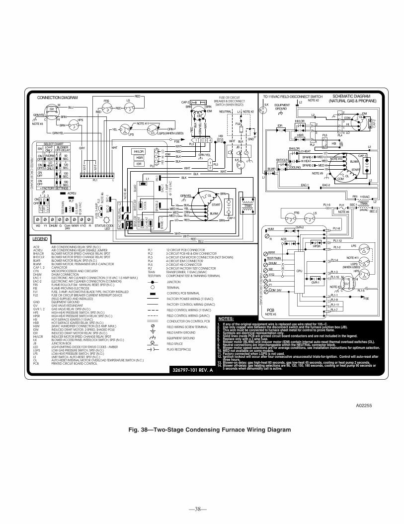
Fig. 38—Two-Stage Condensing Furnace Wiring Diagram
A02255
GV
HI
M
GRN/YEL
CNOTE #3 BRN
BLU
BRN
GRN/YEL
RED
RED
FRS LS
NOTE #11
ORNYEL
HSI
L1 NOTE #2
GND
NEUTRAL
FU2
FUSE OR CIRCUITBREAKER & DISCONNECT
SWITCH (WHEN REQ'D)
BLK
ILK
PL5
JB
1
2
SEC
-1
LED
SEC
-2
FUSE
3-A
MP
PLT
ACRDJ
0.5
AM
P@
24
VA
C
HU
M
TEST
/TW
IN
ONOFF
321
DLY
OFF
LHT
W/W1DHUM G24VomCW2 Y/Y2 RY1
TRAN
L1 PR-1
EAC
-1
OL
SPA
RE -
1
BLW
RBH
T/C
LRBH
I/LO
R
CO
OL
LO-H
EAT
HI-H
EAT
START
GRN/YEL
BLWM
NEU
TRA
L - L
2EA
C-2
RED
BLUORNYELBLK
LOMED LO
MED
HIMED HI
REDBLU
WHTWHT
BRN
BRN
BLK
WHT
BLKWHT
IHI/LOR
HSIR
IDRLO
HI
HSI
GRY
CONNECTION DIAGRAM
BLK
1HSI2
IDM
1
2
3HI
COM
LO
SCHEMATIC DIAGRAM(NATURAL GAS & PROPANE)
IDR
TO 115VAC FIELD-DISCONNECT SWITCH
ILK EQUIPMENT GROUND
1
2
3HSIR
IHI/LOR
PL2
L2
L2
CAP-1
OL
START
BLWM
COM
LOMED LO
MED
HIMED HI
LO HEAT
SPARE-2COOLING
SPARE-1
BHI/LOR
BHT/CLR
BLWR
EAC-2EAC-1
TRAN
L2
L2
115VAC
24VAC SEC 2
SEC 1
PR1
FU1
NOTE #6
PL1-8GVR-2HUM
R ACR PL1-12
HPSR
GV
LPS
NOTE #11
LGPS(WHEN USED)
HPS
HI
PL1-2
PL1-4
PL1-3
PL1-10
PL1-5
W/W1
CPU
GVR-1
TEST/TWIN
DHUM
W2
Y/Y2
G
Y1
COM 24VNOTE #3
C
M
PL1-1
LPS (WHEN USED)LGPS
WHT
FSEPL1-9
PL1-11
PL1-7
LEGEND
ACR AIR CONDITIONING RELAY, SPST (N.O.)ACRDJ AIR CONDITIONING RELAY DISABLE JUMPERBHI/LOR BLOWER MOTOR SPEED CHANGE RELAY, SPDTBHT/CLR BLOWER MOTOR SPEED CHANGE RELAY, SPDTBLWR BLOWER MOTOR RELAY, SPST-(N.O.)BLWM BLOWER MOTOR, PERMANENT-SPLIT-CAPACITORCAP 1, 2 CAPACITORCPU MICROPROCESSOR AND CIRCUITRYDHUM DHUM CONNECTION EAC-1 ELECTRONIC AIR CLEANER CONNECTION (115 VAC 1.0 AMP MAX.)EAC-2 ELECTRONIC AIR CLEANER CONNECTION (COMMON)FRS FLAME ROLLOUT SW. -MANUAL RESET, SPST-(N.C.)FSE FLAME-PROVING ELECTRODEFU1 FUSE, 3 AMP, AUTOMOTIVE BLADE TYPE, FACTORY INSTALLEDFU2 FUSE OR CIRCUIT BREAKER CURRENT INTERRUPT DEVICE
(FIELD SUPPLIED AND INSTALLED)GND EQUIPMENT GROUNDGV GAS VALVE-REDUNDANT GVR 1, 2 GAS VALVE RELAY, DPST-(N.O.)HPS HIGH-HEAT PRESSURE SWITCH, SPST (N.O.)HPSR HIGH-HEAT PRESSURE SWITCH RELAY, SPST (N.C.)HSI HOT SURFACE IGNITER (115VAC)HSIR HOT SURFACE IGNITER RELAY, SPST (N.O.)HUM 24VAC HUMIDIFIER CONNECTION (0.5 AMP. MAX.)IDM INDUCED DRAFT MOTOR, 2-SPEED, SHADED POLEIDR INDUCED DRAFT MOTOR RELAY, SPST-(N.O.)IHI/LOR INDUCER MOTOR SPEED CHANGE RELAY, SPDTILK BLOWER ACCESS PANEL INTERLOCK SWITCH, SPST-(N.O.)JB JUNCTION BOXLED LIGHT-EMITTING DIODE FOR STATUS CODES - AMBERLGPS LOW GAS PRESSURE SWITCH, SPST-(N.O.)LPS LOW-HEAT PRESSURE SWITCH, SPST (N.O.)LS LIMIT SWITCH, AUTO-RESET, SPST (N.C.)OL AUTO-RESET INTERNAL MOTOR OVERLOAD TEMPERATURE SWITCH (N.C.)PCB PRINTED CIRCUIT BOARD CONTROL
PL1 12-CIRCUIT PCB CONNECTORPL2 3-CIRCUIT PCB HSI & IDM CONNECTORPL3 6-CIRCUIT ICM MOTOR CONNECTOR (NOT SHOWN)PL4 4-CIRCUIT IDM CONNECTOR PL5 2-CIRCUIT HSI CONNECTORPLT 3-CIRCUIT FACTORY TEST CONNECTORTRAN TRANSFORMER, 115VAC/24VACTEST/TWIN COMPONENT TEST & TWINNING TERMINAL
JUNCTION
TERMINAL
CONTROL PCB TERMINAL
FACTORY POWER WIRING (115VAC)
FACTORY CONTROL WIRING (24VAC)
FIELD CONTROL WIRING (115VAC)
FIELD CONTROL WIRING (24VAC)
CONDUCTOR ON CONTROL PCB
FIELD WIRING SCREW TERMINAL
FIELD EARTH GROUND
EQUIPMENT GROUND
FIELD SPLICE
PLUG RECEPTACLE
PCB
PL1-6
L1
NOTE #10
L2
PL4PL5
WHT
WHT
RED
BLK
PL2
IDM
NO
TE #
8
1 A
MP
@ 1
15 V
AC
STATUS CODE
FU1
NO
TE #
6
PL1 1
SELECT CHART
SW LO-HTONLY
BLOWEROFF-DELAY
ONOFF
1
ONLYHEAT
LOHEATNORM
2 390
SEC.
ONOFF
1 2 3120SEC.
ONOFF
2 3150SEC.
ONOFF
2 3180SEC.
HPS
FACTORY SETTINGS
BLW
HI HEAT
NOTE #5
*
*
*SP
ARE
-2
FSE
RED
AC
RDJ
326797-101 REV. A
1. If any of the original equipment wire is replaced use wire rated for 105∞C.2. Use only copper wire between the disconnect switch and the furnace junction box (JB).3. This wire must be connected to furnace sheet metal for control to prove flame.4. Symbols are electrical representation only.5. Solid lines inside PCB are printed circuit board conductors and are not included in the legend.6. Replace only with a 3 amp fuse.7. Blower motor (BLWM) and inducer motor (IDM) contain internal auto-reset thermal overload switches (OL).8. Neutral connections are interchangeable within the NEUTRAL connector block.9. Blower motor speed selections are for average conditions, see installation instructions for optimum selection.10. MED not available on some models.11. Factory connected when LGPS is not used.12. Ignition lockout will occur after four consecutive unsuccessful trials-for-ignition. Control will auto-reset after
three hours.13. Blower-on delay: gas high-heat 60 seconds, gas low-heat 45 seconds, cooling or heat pump 2 seconds.14. Blower off-delay: gas heating selections are 90, 120, 150, 180 seconds, cooling or heat pump 90 seconds or
5 seconds when dehumidify call is active.
NOTES:
PRINTED
CIRC
IUT BOA
RD
PRINTED
CIRC
IUT BO
ARD
FRS LS
WH
T
WH
T
PL3
IDM
1 2 3
BLK
4
GR
N/Y
EL
CAP-2BRNBRN
GRN
RED
WH
T
OL
/YEL
CAP-1
NOTE #2
OL
4
CA
P-2
NOTE #9
—38—

2. Operation in all modes (sequence of operation) is the same for twinned furnaces as for an individual furnace. See furnace Installation,Start-Up, and Operating Instructions for more information on sequence of operation.
TWO-STAGE HEAT, TWO STAGE FURNACES WITH 2-STAGE GAS-HEAT THERMOSTAT
NOTE: See Section 2, Procedure 2 - Electrical Connections, Step 3 for control board wiring and LHT switch setup.
1. The 2-stage thermostat (NOT furnace control’s adaptive gas heating mode) determines whether furnaces are both operating in low-gas heator high-gas heat, depending on whether 1 or both thermostat stages (W/W1 or W/W1-and-W2) are calling for heat.
2. Operation in all modes (sequence of operation) is the same for twinned furnaces as for an individual furnace. See furnace Installation,Start-Up, and Operating Instructions for more information on sequence of operation.
Table 5a—Single Stage Heating with Single Stage Thermostat Using 2 Single Stage Furnaces
THERMOSTAT CONNECTIONS CONTROL BOARD CONNECTION ACTIONR R Power from control board to thermostat
W W Starts L/H and R/H furnaces for heating
Table 5b—Single Stage Cooling with Single Stage Thermostat Using 2 Single Stage A/C units
THERMOSTAT CONNECTIONS CONTROL BOARD CONNECTION ACTIONR R Power from control board to thermostat
Y Y/Y2 (Y on standard control board)Energizes accessory cooling relay(s) to start L/H and R/H A/C
for cooling
G G Starts both indoor fans on cooling speed (With Y/Y2 energized)
Dehum* Dehum*Reduces airflow in cooling mode from cooling speed to heating
speed when Dehum input is removed
* Dehum is not available on all thermostats or control boards
Table 6a—Two Stage Heating with Two Stage Thermostat Using 2 Single Stage Furnaces
THERMOSTAT CONNECTIONS CONTROL BOARD CONNECTION ACTIONR R Power from control board to thermostat
W1 W Starts L/H furnace for first stage heating
W2 NoneThermostat W2 wired directly to R/H accessory relay to start
R/H Furnace for second stage heating
Table 6b—Two Stage Cooling with Two Stage Thermostat Using 2 Single Stage A/C units
THERMOSTAT CONNECTIONS CONTROL BOARD CONNECTION ACTIONR R Power from control board to thermostat
Y1 Y/Y2 (Y on standard control board)Energizes accessory cooling relay to start L/H and A/C for first
stage cooling and cooling speed blower
Y2 NoneThermostat Y2 wired directly to R/H accessory relay to start R/H
A/C
G G Starts both indoor fans on cooling speed (With Y/Y2 energized)
Dehum* Dehum*Reduces airflow in cooling mode from cooling speed to heating
speed when Dehum input is removed
* Dehum is not available on all thermostats or control boards
Table 6c—Continuous Fan Operation
THERMOSTAT CONNECTIONS CONTROL BOARD CONNECTION ACTIONR R Power from control board to thermostat
G G Starts both fans in heating speed*
* Staged Continuous Fan operation is not available
—39—

Table 7—Two Stage Heating with Single Stage Thermostat Using 2 Two Stage Furnaces
THERMOSTAT CONNECTIONS CONTROL BOARD CONNECTION ACTIONR R Power from control board to thermostat
W W/W1Starts L/H and R/H furnaces in low heat or high heat, as deter-
mined by L/H furnace control board*
* LHT switches must be in correct configuration
Table 8a—Two Stage Heating with Two Stage Thermostat Using 2 Two Stage Furnaces
THERMOSTAT CONNECTIONS CONTROL BOARD CONNECTION ACTIONR R Power from control board to thermostat
W1 W/W1 Starts both furnaces in low heat for first stage heating*
W2 W2 Starts both furnaces in high heat for second stage heating*
* LHT switches must be in correct configuration
Table 8b—Single Stage Cooling with Single Stage Thermostat Using 2 Single Stage A/C units
THERMOSTAT CONNECTIONS CONTROL BOARD CONNECTION ACTIONR R Power from control board to thermostat
Y Y/Y2Energizes accessory cooling relay to start both A/C units for
cooling
G G Starts both indoor fans on cooling speed (With Y/Y2 energized)
Dehum* Dehum**Reduces airflow in cooling mode from cooling speed to heating
speed when Dehum input is removed
* Do not remove ACRDJ from furnace control boards** Dehum is not available on all thermostats or control boards
Table 8c—Two Stage Cooling with Two Stage Thermostat Using 2 Single Stage A/C units
THERMOSTAT CONNECTIONS CONTROL BOARD CONNECTION ACTIONR R Power from control board to thermostat
Y1 Y/Y2Energizes accessory cooling relay to start L/H A/C for first stage
cooling
Y2 NoneThermostat Y2 wired directly to R/H accessory relay to start R/H
A/C
G G Starts both indoor fans on heating speed until Y/Y2 is energized
Dehum* Dehum**Reduces airflow in cooling mode from cooling speed to heating
speed when Dehum input is removed
* Do not remove ACRDJ from furnace control boards** Dehum is not available on all thermostats or control boards
Table 8d—Continuous Fan Operation
THERMOSTAT CONNECTIONS CONTROL BOARD CONNECTION ACTIONR R Power from control board to thermostat
G G Starts both fans in heating speed*
*Staged Continuous Fan operation is not available
© 2005 CAC/BDP 7310 W. Morris St., Indianapolis, IN 46231 —40— Catalog No. AG-GATW-15