installation instructions - todd's...
TRANSCRIPT
Printed in U.S.A. LP--1 1/23/03 427 01 1004 01
DIRECT DRIVE BLOWER
PH55/PYPA SERIES
SINGLE PACKAGE HEATPUMPS
ELECTRIC HEAT(OPTIONAL)
Installation Instructions
TABLE OF CONTENTS
1. SAFETY LABELING AND SIGNAL WORDS 2. . . . . . . . . . . . . . . . . . . .
2. UNIT DIMENSIONS 2. . . . . . . . . . . . . . . . . . . . . . . . . . . . . . . . . . . . . .
3. SAFE INSTALLATION REQUIREMENTS 2. . . . . . . . . . . . . . . . . . . . . . .
4. LOCATING THE UNIT 2. . . . . . . . . . . . . . . . . . . . . . . . . . . . . . . . . . . .
5. UNIT ELECTRICAL WIRING 4. . . . . . . . . . . . . . . . . . . . . . . . . . . . . . . .
6. WIRING DIAGRAMS 8. . . . . . . . . . . . . . . . . . . . . . . . . . . . . . . . . . . . .
7. ELECTRIC HEAT INSTALLATION GENERAL INFORMATION 10. . . . . .
8. INSTALLING ELECTRIC HEAT ACESSORY 10. . . . . . . . . . . . . . . . . . .
9. HEATER ELECTRICAL WIRING 11. . . . . . . . . . . . . . . . . . . . . . . . . . .
10. RAIN SHIELD INSTALLATION 15. . . . . . . . . . . . . . . . . . . . . . . . . . . .
11. AIR DISTRIBUTION SYSTEM 15. . . . . . . . . . . . . . . . . . . . . . . . . . . . .
12. START-UP PROCEDURES 15. . . . . . . . . . . . . . . . . . . . . . . . . . . . . .
13. SEQUENCE OF OPERATION 17. . . . . . . . . . . . . . . . . . . . . . . . . . . .
14. OPERATION 18. . . . . . . . . . . . . . . . . . . . . . . . . . . . . . . . . . . . . . . . .

2 427 01 1004 01
1. Safety Labeling and Signal Words
Danger, Warning and Caution
Thesignal wordsDANGER,WARNINGandCAUTIONareused to identi-fy levels of hazardseriousness. Thesignal wordDANGER is only usedonproduct labels to signify an immediate hazard. The signal wordsWARN-ING and CAUTION will be used on product labels and throughout thismanual and other manuals that may apply to the product.
2. Dimensions
27
51
26 3/4
3/8 DIA HOLE**
3
10
ROUND FLANGEWILLACCOMMODATE14� DIA.RETURN DUCT
121/2
1 1/4 DIA.*1 1/4 DIA.*
8
41 1/2
ROUND SHAPED FLANGE WILLACCOMMODATE 12� DIA.SUPPLY DUCT
9
* ELECTRICAL ACCESS FOR LINE VOLTAGE POWER SUPPLY--ONE FOR UNIT, ONE FOR HEATER** FOR LOW VOLTAGE WIRING
1 1/2
ALL DIMENSIONS IN INCHES
CONDENSATE DRAINCONNECTION
PRESSUREPORTS
COILACCESSPANEL
NOTE: DUCT COLLARS ATTACHED TO SUPPLY AND RETURN MUST BE REVERSED AT INSTALLATION. SEE INSTRUCTIONS ON PAGE 2.
11/2
17
143/4
3. Safe Installation Requirements
Installation or repairsmade by unqualified persons can resultin hazards to you and others. Installation MUST conform withlocal building codes or, in the absence of local codes, with theNational Electrical Code NFPA70--1990 or current edition.
The information contained in this manual is intended for useby a qualified service technician familiar with safety proce-dures and equipped with the proper tools and test instru-ments.
Failure to carefully read and follow all instructions in thismanual can result in unit malfunction, property damage, per-sonal injury and/or death.
� Seal supply and return air ducts.
� Check to see that filters are installed correctly and are the propertype and size.
NOTE: It is the personal responsibility and obligation of the customer tocontact a qualified installer to ensure that the installation is adequate andconforms to governing codes and ordinances.
CAUTION
DoNOToperate unit in a corrosive atmosphere containing chlorine,fluorine, or any other corrosive chemicals.
4. Locating The Unit
The unit is designed for outdoor installation only. Place the unit on a plat-form at ground level. The unit may be installed on a concrete slab of 48�(1219mm) x 48� (1219mm) dimensions. Cement blocks on a 3�� sandfootingwill alsowork. The slab orblocksSHOULDNOTbe in contactwithany part of the structure. Check local codes covering zoning, noise, plat-forms, etc..
If practical avoid locating next to fresh air intakes, vent or bedroom win-dows. Noise may carry into the openings and disturb people inside.
Avoid installationsunder roofoverhangswithoutguttering. Waterdrainingfrom the roof onto the unit could produceexcessive noise, andmay causeice to build up on coil or fan.
Placement of the unit should be in awell drained areaor the unitMUSTbesupported high enough so runoff will not enter the unit.
Do not locate unit where heat, lint or exhaust fumes will be discharged onunit (as from dryer vents.)
Clearances
Minimum clearances, as specified in FIGURE 1, MUST be maintainedfrom adjacent structures to provide adequate air circulation and room forservice personnel.
While minimum clearances are acceptable for safety reasons, they maynot allow adequate air circulation around the unit for proper operation.Wheneverpossible, it is desirable toallowadditional clearance,especiallyaround the condenser inlet and discharge openings.
DoNOT install the unit in a recessed or confined area that will permit dis-charged air from the condenser to recirculate to the condenser inlet.
3 427 01 1004 01
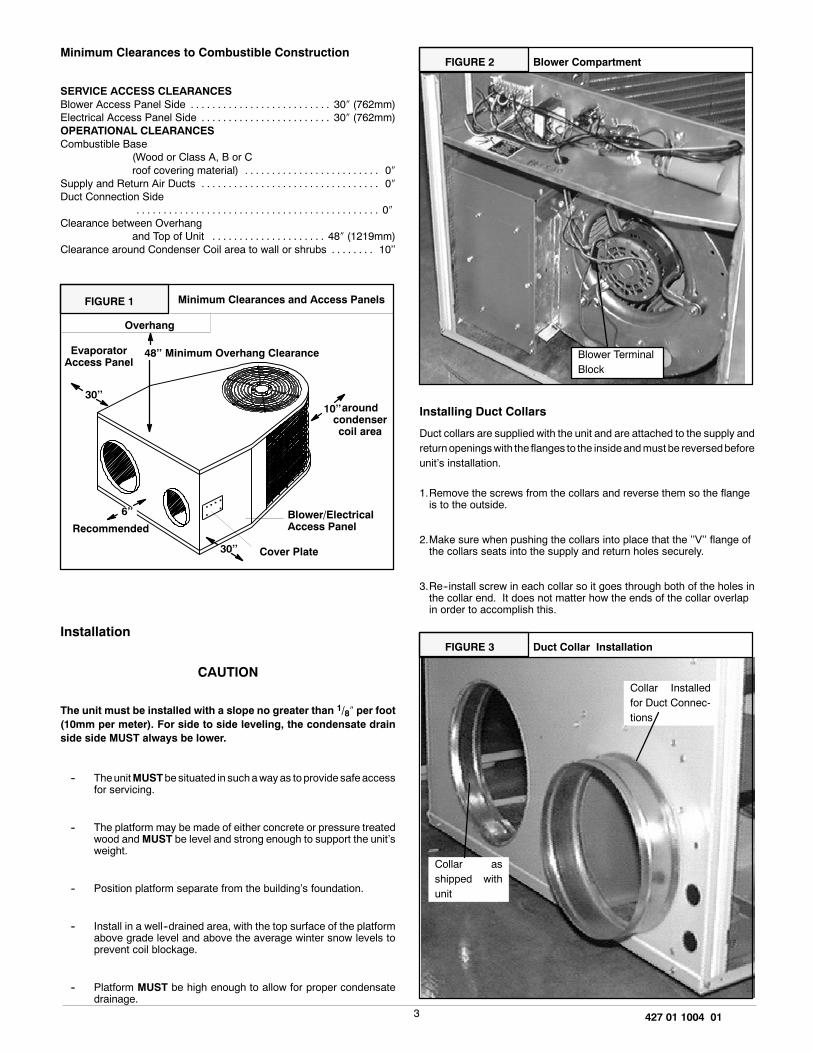
Minimum Clearances to Combustible Construction
SERVICE ACCESS CLEARANCESBlower Access Panel Side 30� (762mm). . . . . . . . . . . . . . . . . . . . . . . . . .Electrical Access Panel Side 30� (762mm). . . . . . . . . . . . . . . . . . . . . . . .OPERATIONAL CLEARANCESCombustible Base
(Wood or Class A, B or Croof covering material) 0�. . . . . . . . . . . . . . . . . . . . . . . . .
Supply and Return Air Ducts 0�. . . . . . . . . . . . . . . . . . . . . . . . . . . . . . . . .Duct Connection Side
0�. . . . . . . . . . . . . . . . . . . . . . . . . . . . . . . . . . . . . . . . . . . . .Clearance between Overhang
and Top of Unit 48� (1219mm). . . . . . . . . . . . . . . . . . . . .Clearance around Condenser Coil area to wall or shrubs 10��. . . . . . . .
FIGURE 1 Minimum Clearances and Access Panels
. . ..
..
Blower/ElectricalAccess Panel
Cover Plate
10��aroundcondensercoil area
30��
EvaporatorAccess Panel
30��
6��
Overhang
48�� Minimum Overhang Clearance
Recommended
Installation
CAUTION
The unit must be installed with a slope no greater than 1/8� per foot(10mm per meter). For side to side leveling, the condensate drainside side MUST always be lower.
-- TheunitMUSTbe situated in suchawayas toprovide safeaccessfor servicing.
-- The platform may be made of either concrete or pressure treatedwood andMUST be level and strong enough to support the unit�sweight.
-- Position platform separate from the building�s foundation.
-- Install in a well--drained area, with the top surface of the platformabove grade level and above the average winter snow levels toprevent coil blockage.
-- Platform MUST be high enough to allow for proper condensatedrainage.
Blower CompartmentFIGURE 2
Blower TerminalBlock
Installing Duct Collars
Duct collars are supplied with the unit and are attached to the supply andreturnopeningswith the flanges to the insideandmust be reversedbeforeunit�s installation.
1.Remove the screws from the collars and reverse them so the flangeis to the outside.
2.Make sure when pushing the collars into place that the ��V�� flange ofthe collars seats into the supply and return holes securely.
3.Re--install screw in each collar so it goes through both of the holes inthe collar end. It does not matter how the ends of the collar overlapin order to accomplish this.
Duct Collar InstallationFIGURE 3
Collar Installedfor Duct Connec-tions
Collar asshipped withunit

4 427 01 1004 01
Condensate Drain
Thecondensatedrainoutlet is a 3/4� (19.1mm) threaded femalePVCcon-nection locatedat thebottomof theunit to the left of theevaporator accesspanel .
The circulating blower and the condenser fan create a negative pressureon the condensate drain line that will prevent the condensate from drain-ing properly without a trap. To combat this negative pressure, a field sup-plied condensate trap that will allow a standing column of water of at least2� (50.8mm)MUST be installed. The outlet of the trap must be at least 1��below the unit drain connection. Install the trap as near to the unit aspossible for proper drainage.
A3/4� (19.1mm)drain lineMUSTbe installed if requiredby local codes or iflocation of unit requires it. Run the drain line to an open drain or other suit-able disposal point.
Condensate Drain Information *FIGURE 4
2� (50.8mm)
1�(25.4mm) 3/4� (19.1mm)
Drain Line
3/4� (19.1mm)Threaded FemalePVC Fitting
* Condensate trap MUST be installed.
33/4�(82.5mm)
5. Unit Electrical Wiring
Electrical shock hazard.
Disconnect power at fuse boxor servicepanel beforemakingany electrical connections.
Unit MUST be grounded to electrical service panel.
Failure to follow this warning can result in property damage,personal injury, and/or death.
NOTE: All electrical work MUST conform with the requirements of localcodes and ordinances and in the United States with National ElectricalCodeANSl/NFPA 70--1990 (or current edition). Provide line voltagepow-er supply from a separate fused circuit with a disconnect switch (when re-quired) located within sight of the unit. Supply voltage, amperage, fuseand disconnect switch sizes MUST conform with local codes and ordi-nances.
WiringMUST be protected from possiblemechanical damage andMUSTNOT interfere with removal of access panels, filters, etc.
All exposed line voltage connectionsMUST be made through liquid tightconduit to prevent water from entering the unit through the electrical ac-cess..
Ground Connections
A ground lug is installed on the control plate (or electric heat mountingplate) for the ground connection. Use a copper conductor of the appropri-ate size from the unit to a grounded connection in the electrical servicepanel or to a properly driven and electrically grounded ground rod. Seewarning on this page.
Line Voltage Wiring
Do NOT complete line voltage connections until unit is permanentlygrounded. All line voltage connections and the ground connectionMUSTbe made with copper wire.
Connections for line voltage are made on the unit electrical control plate(seeFIGURE 6). For access, remove theBlower/Electrical accesspanel.
Refer to applicable wiring diagram in this Manual. Complete the line ser-vice connections to the contactor �L� terminals on the electrical controlplate. Check all screw terminals to ensure they are tight.
NOTE: If an Electric Heat Accessory is installed, refer to the Electric HeatAccessory section of this manual to determine line voltage connections.TheElectricHeatAccessorymounts inside theunit in theheaterbox.Fieldsupplied line voltagewires for theElectric Heat Accessory (separate fromthe field supplied line voltage wires to the unit) connect to the appropriatecircuit breaker (if used) in the Electric Heat Accessory.
Converting 230V Units to 208V
To convert 230V units to 208V:
1.Turn electric power OFF.
2.Remove the blower/electrical access panel.
3.Locate the 24V control transformer.
4.Remove wire from the terminal labeled �240V� on the 24V controltransformer and reconnect it to the 208V terminal of the 24V controltransformer.
5.Replace the electrical/compressor access panel.
Low Voltage Wiring
For access, remove the electrical control/blower access panel.
Refer to the connectionwiring diagram for the applicablemodel and to theinstructions included with the thermostat.
Route low voltage wires through the port located on the rear panel and upto the control box.
NOTE: If anElectric Heat Accessory is installed, see theElectric HeatAc-cessory Installation Section of this manual for low voltage connections.
Thermostat Connections
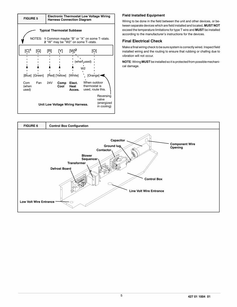
The location of the thermostat has an important effect on the operation ofthe unit. See the thermostat instructions for proper connection. SeeFIGURE 5 for Low Voltage Wire Harness Connections
5 427 01 1004 01
Electronic Thermostat Low Voltage WiringHarness Connection DiagramFIGURE 5
[C]1 [G] [R] [Y] [W]2 [O]
[Blue] [Green] [Red] [Yellow] [White] [Orange]
Typical Thermostat Subbase
Unit Low Voltage Wiring Harness.
Fan 24V CompCool
Elect.HeatAcces.
Com(whenused)
(when used)
W2
NOTES: 1 Common maybe ��B�� or ��X�� on some T--stats.2 ��W�� may be ��W2�� on some T--stats.
When outdoorthermostat isused, route this.
Reversingvalve(energizedin cooling)
Field Installed Equipment
Wiring to be done in the field between the unit and other devices, or be-tween separate devices which are field installed and located,MUSTNOTexceed the temperature limitations for type T wire andMUST be installedaccording to the manufacturer�s instructions for the devices.
Final Electrical CheckMakea finalwiringcheck tobesuresystem is correctlywired. Inspect fieldinstalled wiring and the routing to ensure that rubbing or chafing due tovibration will not occur.
NOTE:WiringMUSTbe installedso it is protected frompossiblemechani-cal damage.
Control Box ConfigurationFIGURE 6
Ground lug Component WireOpening
Low Volt Wire Entrance
Defrost Board
Transformer
BlowerSequencer
Contactor
Capacitor
Control Box
Line Volt Wire Entrance

6 427 01 1004 01
6. Wire Diagrams
2--31/2 Ton Models
IF ANY OF THE ORIGINAL WIRE AS SUPPLIED WITH THE APPLIANCE MUST BE REPLACED, IT MUST BE
REPLACED WITH TYPE AWM−105^C OR ITS EQUIVALENT.
CONNECTION WIRING DIAGRAM
DANGER: ELECTRICAL SHOCK HAZARD DISCONNECT POWER BEFORE SERVICING
USE COPPER CONDUCTORS ONLY
208/230V 60HZ 1PH
* SEE INSTALLATION INSTRUCTIONS FOR PROPER HEATING AND COOLING CONNECTIONS FOR YOUR UNIT
Y
LOW VOLTAGE FIELD
R
GRAY GY VIOLET V
C
DFC
R−RV
DF
Y−RV
R WYO
W
Y
O
BL
IFMC
BL
BL
G
GND
PS2
PS1
CC
RV
CAPHI
MED
LO
COM
BR
BR
*
G
R
(G) FAN
(R) 24 VAC
(C) COMMON
(O) HEAT/COOL
(Y) COMPRESSOR
BK
C
S
R
BL
COMPRH
C
DUAL
CAP
C
F
S
OFM
BR
R
BKBK
T1
L1
T2
COIL
CONTL2
BK
BK
LOW VOLTAGE FACTORY
LINE VOLTAGE FIELDBROWN BR
LINE VOLTAGE FACTORY
RED R
COLOR CODE :BLUE BL
BLACK BK
R
R
R
PRI
TRANS
SEC
3COIL1
42
5
RVC
(W) DEFROST HEAT
LOC ORJPR
WHITE W
YELLOW Y
GREEN G
ORANGE O
DFS
ELECT. HEAT
PACKAGE
(WHEN USED)
IFM
Y
BK
R
BK
GND
LUG
BK
BKBK
Y
Y
YBL
BK
BKFAN
DEFROST
CONTROL
Y
1081362

7 427 01 1004 01
Wire Diagrams (Cont�d...)
2--31/2 Ton Models
IFMC......INDOOR FAN MOTOR CONTROL
IFM........INDOOR FAN MOTOR
RVS........REVERSING VALVE SOLENOID
OFM........OUTDOOR FAN MOTOR
TC..........TERMINAL CONNECTOR
TRANS....TRANSFORMER
COMPR....COMPRESSOR
CAP........CAPACITOR
CONT......CONTACTOR
JPR........JUMPER WIRE
L1
H
L2208/230 VAC, 60 HZ, 1PH
GND
LADDER WIRING DIAGRAM
DFS
RVS
LOC ORJPR
GND.......GROUND
LOC.......LOSS OF CHARGE
PRESSURE SWITCH
DFS........DEFROST SENSOR
DFC........DEFROST CONTROL
COILCONT
1081362
(O) HEAT/COOL
(Y) COMPRESSOR
(R) 24 VAC
(W) DEFROST HEAT
(G) FAN
LEGEND
R C OR−RV
Y
(C) COMMON
W
GND
3
1
COIL
T1
HEATER PKG
WHEN USED
IFMC
24V
CONTACTORL1
(OPTIONAL) CRANKCASE HEATER
FAN
DFS
DEFROST
CONTROL
RV
Y−RV
CC
PS2
PS1
DF
S
R
R
S
C
COMHIMED*4
5
2
LO CAP
F
C
230V
OFM
L2
TRANS
208V TAP
COMPRT2
CAP
CONTACTOR
IFM
FAN
DFC
C
DANGER: ELECTRICAL SHOCK HAZARD DISCONNECT POWER BEFORE SERVICING

8 427 01 1004 01
Wire Diagrams (Cont�d...)
4 & 5 Ton Model
* SEE INSTALLATION INSTRUCTIONS FOR PROPER HEATING AND COOLING CONNECTIONS FOR YOUR UNIT
WHITE W
YELLOW Y
GREEN G
ORANGE O
RED R
VIOLET V
BLACK BK
BLUE BL
BROWN BR
GRAY GY
:
CAP
COLOR CODE
BR
*
GCOM
HI
MED
1081364
IF ANY OF THE ORIGINAL WIRE AS SUPPLIED WITH THE APPLIANCE MUST BE REPLACED, IT MUST BE
REPLACED WITH TYPE AWM−105^C OR ITS EQUIVALENT.
LINE VOLTAGE FACTORY
LINE VOLTAGE FIELD
LOW VOLTAGE FACTORY
LOW VOLTAGE FIELD
COIL1
5
BK
2
G
BK
R
Y
IFMC
PRI
TRANS
SECBK
R
LOBR
3
4
GND
BL
C
BKBK
Y
O
Y
FAN
BK
LOC OR
BK
BL
(Y) COMPRESSOR
(W) DEFROST HEAT
(O) HEAT/COOL
(R) 24 VAC
R
BK
R
ELECT. HEAT
PACKAGE
(WHEN USED)
Y
(G) FAN
BK
T2T1
L2
COIL
CONT
OFM
L1
R
SBL
BRDUALCAP
FS
HCOMPR
C
R
R
C
USE COPPER CONDUCTORS ONLY 208/230V 60HZ 1PH
CONNECTION WIRING DIAGRAM
DANGER: ELECTRICAL SHOCK HAZARD DISCONNECT POWER BEFORE SERVICING
R
C
DFS
Y
OR Y
W
DF
W
(C) COMMON
PS1
R−RV
CC
PS2
RV
DEFROST
CONTROL
DFCRVC
JPR
Y
BL
BL
Y−RV
Y
IFM
GND
LUG
BK
BK
BK
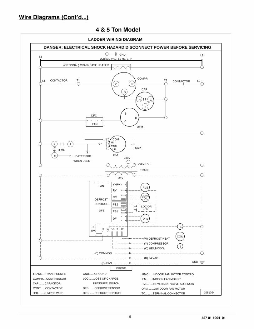
9 427 01 1004 01
Wire Diagrams (Cont�d...)
4 & 5 Ton Model
LOC ORJPR
RVS
PS1
PS2
CC COIL
DFS
RV
FAN Y−RV
(W) DEFROST HEAT
DFS
DF
O Y W
CONT
L1 CONTACTOR T1
H C
F
DFC
FANC
OFM
IFMC
HEATER PKG
WHEN USED
IFM230V
208V TAP
TRANS
24V
TRANS....TRANSFORMER
COMPR....COMPRESSOR
CAP........CAPACITOR
CONT......CONTACTOR
JPR........JUMPER WIRE
LEGEND
GND.......GROUND
LOC.......LOSS OF CHARGE
PRESSURE SWITCH
DFS........DEFROST SENSOR
DFC........DEFROST CONTROL
(C) COMMON
(G) FAN
L2
COMPRT2
CAP
CONTACTOR L2C R
S
S
4
R
*
1081364
(O) HEAT/COOL
(Y) COMPRESSOR
(R) 24 VAC
208/230 VAC, 60 HZ, 1PH
DEFROST
CONTROL
R−RV
R C
GND
LADDER WIRING DIAGRAM
IFMC......INDOOR FAN MOTOR CONTROL
IFM........INDOOR FAN MOTOR
RVS........REVERSING VALVE SOLENOID
OFM........OUTDOOR FAN MOTOR
TC..........TERMINAL CONNECTOR
(OPTIONAL) CRANKCASE HEATER
L1
2
5
COMHIMED
LO CAP
DANGER: ELECTRICAL SHOCK HAZARD DISCONNECT POWER BEFORE SERVICING
1
3
COIL
GND

10 427 01 1004 01
7. Electric Heat Installation GeneralInformation
General Information
WARNINGInstallationor repairsmadebyunqualifiedpersonscanresultin hazards to you and others. Installation must conform withlocal building codes or, in the absence of local codes, withNational Electrical Code ANSI/NFPA 70--1990 or currentedition.
The information contained in this manual is intended for useby a qualified service technician familiar with safetyprocedures, equipped with the proper tools and testinstruments.
Failure to carefully read and follow all instructions in thismanual can result inmalfunction, propertydamage,personalinjury, and/or death.
When an electric heat accessory is installed, two separate field powersuppliesMUSTbeprovided -- oneormore for theelectric heat accessoryand one for the unit.
FIGURE 7 The Electric Heat Accessory
Breaker-- Style Heater Pigstyle--Style Heater
8. Installing Electric Heat Accessory
Electrical shock hazard.
Shut OFF electric power at unit disconnect and/or servicepanel before beginning the following procedures.
Failure to follow this warning can result in property damage,personal injury, and/or death.
1. Shut OFF electric power at unit disconnect switch or service panel.
2. Remove the blower access panel from unit.NOTE: Installation of field wiring and conduit for heaters to theunit prior to installing the heater will simplify wiring of heaters.
3. From inside the blower compartment, remove the six screws on theheater cover plate and save the screws. Discard the heater coverplate.
The screws will be used later to mount the electric heat accessoryand its cover.
4.Remove the cardboard wrapper from the heater�s elements.
5.Insert the heater into the heater/blower box. Exercise caution toprevent damage to heater elements.
6.Secure heater to heater/blower box with four of the six screws re-moved in Step 3.
FIGURE 8 Installing The Electric Heat Accessory
Heater Box
11 427 01 1004 01
9. Heater Electrical Wiring
Electrical shock hazard.
Shut OFF electric power at unit disconnect or service panelbefore making any electrical connections.
Unit MUST be grounded before making line voltage connec-tions. Do NOT fuse ground or neutral conductors.
Failure to follow this warning can result in property damage,personal injury, and/or death.
NOTE: All electrical work MUST conform with the requirements of localcodes and ordinances and in the United States with National ElectricalCode ANSI/NFPA70--1990 or current edition. Provide line voltage powersupply from a separate protected circuit with a disconnect switch (whenrequired) located within sight of the unit. Supply voltage, amperage, fuseand disconnect switch sizes MUST conform with all technical specifica-tions in this manual and on the unit rating plate and local codes.
WiringMUST be protected from possiblemechanical damage andMUSTNOT interfere with removal of access panels, filters, etc.
All exposed wiring or connections MUST be made with weatherproofcable or wire unless installed in conduit.
All line voltage connections and the ground connection MUST be madewith copper wire.
The power supply wiringMUST have overcurrent protection. This can beeither fuses or circuit breakers. The maximum size for the overcurrentprotection is shown in the column labeled �Max. Fuse or NEC HACRBreaker (Amps)� in the Electrical Data Table in FIGURE 10 or on the unitrating plate.
Grounding
Permanently ground the electric heat accessory in accordance with localcodes and ordinances and in the United States with National ElectricalCode ANSI/NFPA70--1990 or current edition. Use a copper conductor ofthe appropriate size from the electric heat accessory to the ground lug onthe circuit breaker panel as shown in FIGURE 9.
Adjusting Thermostat Anticipator
Set the heat anticipator of the thermostat to the proper value. See instruc-tions provided with the thermostat before making this adjustment.
Model Number AnticipatorSetting
AMMK05AHB/A .18
AMMK07AHB/A .36
AMMK10AHB/A .36
AMMK15AHB/A .36
AMMK20AHB/A .54
Limit ControlsThe limit controls aremounted on the face of the heater and arewired intothe supply wires to each element. If there is not enough air flow throughthe heater, the limit will open and break the power circuit. The limit will re-set when the electric accessory cools down.
Time Delay OperationThe heater elements are switchedON andOFF through one ormore con-trols which operate through the low voltage thermostat circuit.
These controls consist of a number of time delays depending on the spe-cific heater model. An electric heat accessory has 1, 2 or 3 of these con-trols. The first time delay is activatedwhen the thermostat contacts close.Approximately 1 to 20 seconds later the indoor blower and the first heaterbank are energized. Approximately 70 seconds after the first heater bankis energized the remaining time delays and heater banks are energized.
StagingSomeelectric utilities require stagingonelectric heaters larger than6kilo-watts. Therefore, the heater elements are turned on in 5 or 10 kW incre-ments under control of the sequencers.
If staging based on heat loss or demand is required, the use of accessoryoutdoor thermostats is recommended. The heat sequencer wiring is de-signed to be staged by breaking the 24V �Common� Leg (normally brownor gray). Outdoor thermostats available through your wholesale supplierallow the control of two or four stages of electrical heat.
Some indoor electronic thermostats may provide for multiple stage ofelectric heat. When this type thermostat is used, it may be necessary tobreak the 24V �Hot� leg of the sequencer (as fed from the �W� circuit at thethermostat). This will require field modification of the control wiring andshould only be done by an experienced controls technician/or electrician.
Installing Wiring
1.Shut OFF electric power at unit disconnect or service panel.
2.Install the appropriate field supplied conduit fitting into the heaterknockout located in the rear panel of the unit. The wiring entrancehole is sized for 1�� conduit.
12 427 01 1004 01
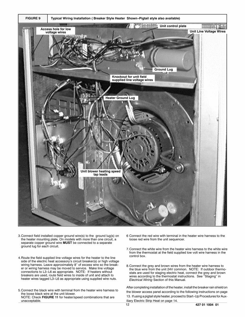
FIGURE 9 Typical Wiring Installation ( Breaker Style Heater Shown--Pigtail style also available)
Unit blower heating speedtap leads
Access hole for lowvoltage wires
Knockout for unit fieldsupplied line voltage wires
Unit control plate
Ground Lug
Heater Ground Lug
Unit Line Voltage Wires
3.Connect field installed copper ground wire(s) to the ground lug(s) onthe heater mounting plate. On models with more than one circuit, aseparate copper ground wire MUST be connected to a separateground lug for each circuit.
4.Route the field supplied line voltage wires for the heater to the lineside of the electric heat accessory�s circuit breaker(s) or high voltagewiring harness. Leave approximately 8�� of excess wire so the break-er or wiring harness may be moved to service. Make line voltageconnections to L3--L6 as appropriate. NOTE: If heaters withoutbreakers are used, route field wires to inside of unit and attach toheater wires tagged L3--L6 as appropriate using supplied wire nuts.
5.Connect the black wire with terminal from the heater wire harness tothe loose black wire at the unit blower.NOTE: Check FIGURE 11 for heater/speed combinations that areunacceptable.
6 Connect the red wire with terminal in the heater wire harness to theloose red wire from the unit sequencer.
7.Connect the white wire from the heater wire harness to the white wirefrom the thermostat at the field supplied low volt wire harness in thecontrol box.
8.Connect the grey and brown wires from the heater wire harness tothe blue wire from the unit 24V common. NOTE: If outdoor thermo-stats are used for staging electric heat, connect the grey and brownwires according to the thermostat instructions. See ��Staging�� inElectrical Wiring Section of this Manual.
After completing installationof theheater, install the breaker rain shieldonthe blower access panel according to the following instructions on page13. If using apigtail styleheater, proceed toStart--UpProcedures forAux-iliary Electric Strip Heat on page 14.

13 427 01 1004 01
FIGURE 10 Accessory Electric Heater Electrical Data
HEATERMODEL Used With Supply Voltage KW Rating
Nominal HeatingBTUH
SupplyCircuit No.
HeaterAmps
Mininum CircuitAmpacity
Maximum OvercurrentProtective Device
(Amps)AMMK05AHA 2--5 TON 240--1--60 4.8 16,382 L3 - L4 20.0 25.0 30AMMK05AHB 208--1--60 3.6 12,287 L3 - L4 17.3 21.6 25
AMMK07AHA 2--5 TON 240--1--60 7.5 25,598 L3--L4 31.2 39.1 45AMMK07AHB 208--1--60 5.6 19,113 L3--L4 26.9 33.6 40
AMMK10AHA 2--5 TON 240--1--60 9.6 32,765 L3 - L4 40.0 50.0 60AMMK10AHB 208--1--60 7.2 24,574 L5 - L6 34.6 43.3 50
AMMK15AHB 2 1/2--5 TON 240--1--60 14.4 49,147 L3 - L4L5 - L6
40.020.0
50.025.0
6030
208--1--60 10.8 36,860 L3 - L4L5 - L6
34.617.3
43.321.6
5025
AMMK20AHB 2 1/2--5 TON 240--1--60 19.2 65,530 L3 - L4L5 - L6
40.040.0
50.050.0
6060
208--1--60 14.4 49,147 L3 - L4L5 - L6
34.634.6
43.343.3
5050
FIGURE 11 Accessory Electric Heater Heating Data*Temperature Rise �F @ CFM (Electric Heat Only)
HeaterModel Use With Supply Voltage KW Rating
Total HeatingBTUH 600 800 1000 1200 1400 1600 1800 2000 2200
AMMK05AHA 2--5 TON 240--1--60 4.8 16,832 25.3 19.0 15.2 12.6 10.8 9.5 8.4 7.6 ---- --AMMK05AHB 208--1--60 3.6 12,287 19.0 14.2 11.4 9.5 8.1 7.1 6.3 5.7 ---- --AMMK07AHA 2--5 TON 240--1--60 7.5 25,598 39.5 29.6 23.7 19.8 16.9 14.8 13.2 11.9 10.8AMMK07AHB 208--1--60 5.6 19,113 29.5 22.1 17.7 14.7 12.6 11.1 9.8 8.8 8.0AMMK10AHA 2--5 TON 240--1--60 9.6 32,765 50.6 37.9 30.3 25.3 21.7 19.0 16.9 15.2 13.8AMMK10AHB 208--1--60 7.2 24,574 37.9 28.4 22.8 19.0 16.3 14.2 12.6 11.4 10.3AMMK15AHB * 2 1/2--5 TON 240--1--60 14.4 49,147 ---- -- 56.9 45.5 37.9 32.5 28.4 25.3 22.8 20.7
208--1--60 10.8 36.860 56.9 42.7 34.1 28.4 24.4 21.3 19.0 17.1 15.5AMMK20AHB ** 2 1/2--5 TON 240--1--60 19.2 65,530 ---- -- -- -- -- -- -- -- 50.6 43.3 37.9 33.7 30.3 27.6
208--1--60 14.4 49,147 ---- -- 56.9 45.5 37.9 32.5 28.4 25.3 22.8 20.7* 15 KW HEATER NOT TO BE OPERATED ON LOW TAP FOR 2 1/2 TON A/C AND HP.** 20 KW HEATER NOT TO BE OPERATED ON LOW OR MEDIUM LOW TAP FOR 3 AND 3 1/2 A/C AND HP.
14 427 01 1004 01
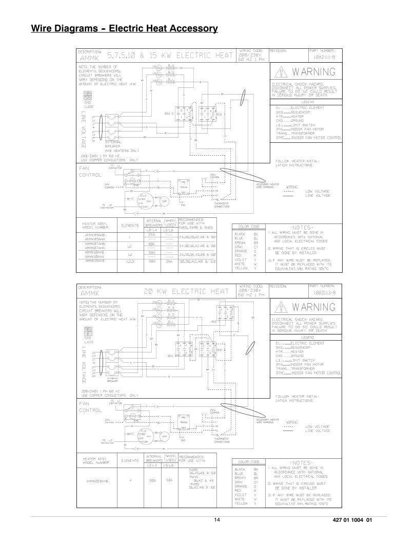
Wire Diagrams -- Electric Heat Accessory
15 427 01 1004 01
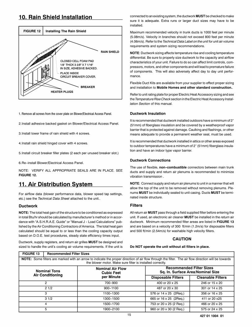
10. Rain Shield Installation
FIGURE 12 Installing The Rain Shield
RAIN SHIELD
BREAKER
HEATER PLUGS
1. Remove all screws from the cover plate on Blower/Electrical Access Panel.
2.Install adhesive backed gasket on Blower/Electrical Access Panel.
3.Install lower frame of rain shield with 4 screws.
4.Install rain shield hinged cover with 4 screws.
5.Install circuit breaker filler plates (2 each per unused breaker slot.)
6.Re--install Blower/Electrical Access Panel.
NOTE: VERIFY ALL APPROPRIATE SEALS ARE IN PLACE. SEEFIGURE 12.
11. Air Distribution System
For airflow data (blower performance data, blower speed tap settings,etc.) see the Technical Data Sheet attached to the unit..
Ductwork
NOTE:The total heat gain of the structure to be conditionedas expressedin total Btu/hr should be calculated bymanufacturer�s method or in accor-dance with �A.S.H.R.A.E. Guide� or �Manual J -- Load Calculations� pub-lished by theAir ConditioningContractors of America. The total heat gaincalculated should be equal to or less than the cooling capacity outputbased on D.O.E. test procedures, steady state efficiency times input.
Ductwork, supply registers, and return air grilles MUST be designed andsized to handle the unit�s cooling air volume requirements. If the unit is
connected toanexistingsystem, theductworkMUSTbechecked tomakesure it is adequate. Extra runs or larger duct sizes may have to beinstalled.
Maximum recommended velocity in trunk ducts is 1000 feet per minute(5.08m/s). Velocity in branches should not exceed 800 feet per minute(4.06m/s). Refer to theTechnical Data Label on theunit for unit air volumerequirements and system sizing recommendations.
NOTE: Ductwork sizing affects temperature rise and cooling temperaturedifferential. Be sure to properly size ductwork to the capacity and airflowcharacteristics of your unit. Failure to do so can affect limit controls, com-pressors,motors, andother components andwill lead topremature failureof components. This will also adversely affect day to day unit perfor-mance.
Flexible Duct Kits are available from your supplier to effect proper sizingand installation to Mobile Homes and other standard construction..
Refer to unit ratingplate for properElectricHeat Accessory sizing andseetheTemperatureRiseChecksection in theElectricHeatAccessory Instal-lation Section of this manual.
Ductwork Insulation
It is recommended that ductwork installed outdoors have aminimumof 2�(51mm) of fiberglass insulation and be covered by a weatherproof vaporbarrier that is protected against damage. Caulking and flashings, or othermeans adequate to provide a permanent weather seal, must be used.
It is recommended that ductwork installed in attics orother areasexposedto outdoor temperatures have aminimum of 2� (51mm) fiberglass insula-tion and have an indoor type vapor barrier.
Ductwork Connections
The use of flexible, non--combustible connectors between main trunkducts and supply and return air plenums is recommended to minimizevibration transmission .
NOTE: Connect supply and return air plenums to unit in amanner that willallow the top of the unit to be removed without removing plenums. Ple-numsMUST be individually sealed to unit casing. DuctsMUST be termi-nated inside structure.
Filters
All return airMUST pass through a field supplied filter before entering theunit. If used, an electronic air cleanerMUST be installed in the return airductwork. Minimum recommended filter areas are listed in FIGURE 13and are based on a velocity of 300 ft/min (1.2m/s) for disposable filtersand 500 ft/min (2.54m/s) for washable high velocity filters.
CAUTION
Do NOT operate the unit without all filters in place.
FIGURE 13 Recommended Filter Sizes
NOTE: Some filters are marked with an arrow to indicate the proper direction of air flow through the filter. The air flow direction will be towardsthe blower motor. Make sure filter is installed correctly.
Nominal TonsAir Conditioning
Nominal Air FlowCubic Feet
Recommended Filter SizesSq. In. Surface Area/Nominal Size
Air ConditioningCubic Feetper Minute Disposable Filters Cleanable Filters
2 700--900 400 or 20 x 25 246 or 15 x 20
2 1/2 900--1100 487 or 20 x 30 301 or 14 x 25
3 1100--1300 576 or 14 x 25 (2Req.) 356 or 16 x 25
3 1/2 1300--1500 665 or 16 x 25 (2Req.) 411 or 20 x25
4 1500--1700 753 or 20 x 25 (2 Req.) 466 or 20 x 25
5 1900--2100 960 or 20 x 30 (2 Req.) 575 or 24 x 25

16 427 01 1004 01
12. Start--up Procedures
Electrical shock hazard.
Use extreme care during all of the following checks and pro-cedures.
Make sure electric power is turned OFF as instructed in ap-propriate steps.
Failure to follow this warning can result in property damage,personal injury, and/or death.
Circulating Air Blower
Determining Blower Speed
1.Turn electric power OFF.
2.From the system design, determine the total external static pressure(ESP) for the supply ducts, return ducts and registers, diffusers,grilles, dampers, heaters and filters.
3.To your system ESP determined in Step 2, add 0.05 In. W.C. for awet coil.
4.From the system design, determine the desired cooling airflow incubic feet per minute (CFM).
5.Locate the unit�s Blower Performance Data table on the tech datalabel for the unit�s voltage. (The tech data sheet is attached to theevaporator access panel on the unit.) From the table, determine thespeed tap required to achieve the desired airflow.
6.See next section, Speed Taps, to set the blower motor speed termi-nal block (speed taps) to the cooling speed determined in the pre-vious steps.
Speed Taps
After determining the requiredCFMandspeed tapdata from the techdatasheet, follow the steps below to change speeds if necessary.
FIGURE 14 Blower Speed Tap Settings
10 SEER 2 TON MED10 SEER 21/2 TON MED10 SEER 3 TON LOW10 SEER 31/2 TON MED HI10 SEER 4 TON LOW10 SEER 5 TON HI
FIGURE 15 Blower Motor Speed Taps
BE SURE TO CHECK BLOWER MOTOR SPEED DATA ON THEUNITS TECHNICAL DATA LABEL LOCATED ON THE UNIT.
Auxiliary Electric Heat BlowerWire (if used)connects here
C O M
H I
M E D
L O
Yellow
Black
Blower Speed Tap Block
MO
TOR
NOTE: On Heat Pumps Electric heater blower wire must be attached tothe same speed tap required for cooling/heat pump operation. See FIG-URE11notes. Theyellow leadMUST always be connected to the speedtapblock at the commonquick connect terminal. The terminal is identifiedas COM.
Refer to FIGURE 15 and the appropriate unit wiring diagram included inthis manual. Wire the black wire to the required speed tap terminal toachieve required airflow determined in Step 5.
Cooling, Heating (Heat Pump) and AuxiliaryElectric Strip Heat
NOTE: The cooling, heat pumpand strip heat airflows are all on the samespeed tap. The refrigerant system requires the same specific CFM forproper operation in the cooling and the heat pumpmode. For this reason,cooling andheatingairflowmust be thesame. DONOTSPLITOUT INTOACOOLING SPEEDANDHEATINGSPEED. If auxiliary electric heat isinstalled, the auxiliary electric heat blower speedwiremust be connectedto the black wire insulated quick connect terminal.
Check Before Starting
1. Check that the blower motor speed terminal block is set to the prop-er cooling speed. Refer to the unit wiring diagram and the variousairflow tables in this manual.
2. Check to see that clean, properly sized field supplied air filters areinstalled in the return air duct.
3. Inspect the inside of the unit to be sure that all wires are in place andall tools, etc. are removed.
4. Replace all service access panels.
Check the unit�s operation as outlined in the following instructions. If anyunusual sparking, odors or noises are encountered, shut OFF electricpower immediately. Recheck for wiring errors, or obstructions in or nearblower motors.
17 427 01 1004 01
Circulating Air Blower
1.Be sure electric power is OFF.
2.Set thermostat Heat--Cool selector to OFF.
3.Set thermostat fan switch to AUTO.
4.Turn electric power ON. Nothing should start running.
5.Set thermostat fan switch to ON. The circulating air blower shouldcome ON after a 30 second delay.
6.Reset thermostat fan switch to AUTO. The circulating air blowershould go OFF after a 30 second delay. Nothing should be running.
Cooling
1. Be sure that electric power is OFF.
2. Set thermostat Heat--Cool select to COOL.
3. Adjust thermostat setting to below room temperature.
4. Turn electric power ON. During power application check the follow-ing:
a. Contactor -- Contacts closingb. Compressor -- ONc. Condenser fan motor -- ONd. Circulating air blower -- ON (after delay)
5.Switch the thermostat to OFF, check the following:
a. Contactor contacts opening.b. Compressor -- OFFc. Condenser fan motor -- OFFd. Circulating blower -- OFF (after delay)
6.Turn electric power OFF
Auxiliary Heating
NOTE: Repeat circulating air blower procedure above if Auxiliary ElectricHeat is being installed after unit has been installed and checked out.
Temperature Rise Check
Temperature rise is the difference between the supply and return air tem-peratures. The temperature rise should be � 2�F (1.1�C) of the tempera-ture rise shown in FIGURE 11 .
NOTE: The temperature rise can be adjusted by changing the heatingspeed tapat theunit�s blower terminal block.Refer to the unit�s InstallationInstructions for airflow information.
A temperature rise greater than60�F (33.3�C) is not recommended. (Thisapplies to electric heat only).
1.To check the temperature rise through the unit, place thermometersin the supply and return air ducts as close to the unit as possible.
2.Open ALL registers and duct dampers.
3.Set thermostat Heat--Cool selector to HEAT.
4.Set the thermostat temperature setting as high as it will go.
5.Turn electric power ON.
6.Operate unit AT LEAST 5 minutes, then check temperature rise.
NOTE: The maximum outlet air temperature for all models is 200�F(93.35C). Maximum temperature rise for electric heat is 60�F (33.35C)
If temperature rise is excessive, verify proper airflow through the unit. Iftemperature rise is inadequate, check for proper electrical supply to theheater and verify correct airflow.
7.Set thermostat to normal temperature setting.
8.Turn electric power OFF.
9.Change blower speed tap if 60�F (33.3�C) Temperature Rise was exceededand repeat.
10.Be sure to seal all holes in ducts if any were created during thisprocess.
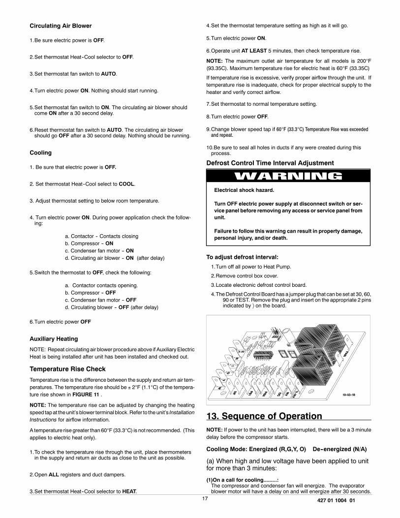
Defrost Control Time Interval Adjustment
Electrical shock hazard.
Turn OFF electric power supply at disconnect switch or ser-vice panel before removing any access or service panel fromunit.
Failure to follow this warning can result in property damage,personal injury, and/or death.
To adjust defrost interval:
1.Turn off all power to Heat Pump.
2.Remove control box cover.
3.Locate electronic defrost control board.
4.TheDefrost Control Board has a jumper plug that canbe set at 30, 60,90 or TEST. Remove the plug and insert on the appropriate 2 pinsindicated by � on the board.
13. Sequence of OperationNOTE: If power to the unit has been interrupted, there will be a 3 minutedelay before the compressor starts.
Cooling Mode: Energized (R,G,Y, O) De--energized (N/A)
(a) When high and low voltage have been applied to unitfor more than 3 minutes:
(1)On a call for cooling.........:The compressor and condenser fan will energize. The evaporatorblower motor will have a delay on and will energize after 30 seconds.

18 427 01 1004 01
(2)When the cooling setpoint has been satisfied.........:The compressor and condenser fan will de--energize immediately.The evaporator blower motor will have a delay off and will de--ener-gize after 30 seconds.
Heat Mode (Heat Pump Only): Energized (R,G,Y)De--energized (O)
(a) When high and low voltage have been applied to unitfor more than 3 minutes:
(1) On a call for heating.........:The compressor and condenser fan will energize (there will be a 3minute delay on 4 Tonmodel with anti--cycle timer). The evapora-tor blower motor will have a delay on andwill energize after 30 se-conds. Thedelayon for thecompressorand thecondenser fancanbe by--passed by jumpering the test pins on the defrost controlboard .
(2) When the heating setpoint has been satisfied.........:Thecompressor and condenser fanwill de--energize immediately.Theevaporator blowermotorwill haveadelay off andwill de--ener-gize after 30 seconds.
Defrost Mode:Energized (R,G,Y) De--energized (O) DefrostSensor Closed
(1) On a call for defrost.........When the defrost sensor closes in the heating mode,there is a 30,60 or 90 minute delay before the defrost mode begins. This delayis selected by the position of a jumper on the defrost board
In normal defrostmode, the following sequencewill occur after theset delay:
1. Condenser fan off.
2. Reversing valve energized to cooling and auxillary electricheat (��W�� circuit) is energized.
3. After defrost sensor opens or a maximum of 10 minutes; thecondenser fan is energized immediately. After a 10--12 seconddelay the reversing valve is then de--energized to the heat mode.Electric strip heat is also de--energizedexcept as required by ther-mostat.
To check out the defrost mode, place jumper across the two tabsmarked �DF�. This simulates the defrost sensor closing. Thedelaycanbeby--passedby jumpering the test pins on the defrost controlboard (this reduces the delay from 30 minutes to 7 seconds, from60minutes to 14 seconds and from 90minutes to 21 seconds). Inthe defrost mode the reversing valve will energize and the con-denser fan will de--energize.
NOTE: If the jumper on the defrost delay selection is left in the �TEST�mode, the board will default to 90 min. delay until power is off.
(2) When defrost has been completed.........This condition will be maintained until the defrost sensor opens oruntil the defrost mode operates for 10minutes (or 2 seconds if testpins are jumpered), whichever comes first.
Adding Accessories
Low/High Pressure Controls
This unit is equippedwith extra low andhigh pressure ports located insidetheunit panelwhere theexternal highand lowpressureports are installed.This allows for installation of high and low pressure controls or low ambi-ent controls.
14. Operation
Scroll Anti--Cycle Timer (Where Applicable)
Single phaseunits with scroll compressorsmaybeequippedwith ananti--cycle device which delays the start of the compressor in the event of apower interruption. This equalizes pressure throughout the system andprevents possible reverse rotationof thescroll compressor. Later produc-tion scroll compressors are equipped with an anti--reverse device to pre-vent thecompressor fromrunningbackwards, soananti--cycle timer isnotneeded on these models.
CAUTION
DoNOToperateunit oncoolingwhen theoutdoor temperature isbe-low 60�F. This is necessary to prevent possible damage to the com-pressor.
Loss of Charge Pressure Switch
Scroll compressor bearing units are equipped with a low pressure switchon the liquid line (high side) which has been installed to prevent systemdamagedue toa lossof charge. Theswitchwill openandde--energize thecontactor if the high side pressure drops below the set point of the switch.
INTERNATIONAL COMFORT PRODUCTSLIMITED WARRANTY CERTIFICATEFor Cooling & Heating Products
SAVE THIS CERTIFICATE. It gives you specific legal rights, and you may also have other rights which may vary from state to state andprovince to province.
If your unit needs servicing, contact a qualified dealer or qualified service technician of your choice. When requesting service, please have themodeland serial number fromeach unit in your heating and/or cooling system readily available. If your dealer needs assistance, the distributor is available toprovide support and we, in turn, support its efforts.
Fill in the installation date and model and serial numbers of the unit in the space provided below and retain this Limited Warranty for your files.
GENERAL TERMS
Subject to the conditions and limitations stated herein, during the term of this Limited Warranty, we will provide a replacement for any functionalcomponent part (as defined below) of your unit found to be defective in materials or workmanship. The term of this LimitedWarranty is five years frominstallation on Residential Products and one year from installation on Commercial Products. Except as otherwise stated in the ��Additional Terms��section, this LimitedWarranty covers only the original purchaser and subsequent transferees, and only while the unit remains at the site of the originalinstallation (except for mobile home installations), and only if the unit is installed inside the continental United States, Puerto Rico, Alaska, Hawaii orCanada. Inaddition, theLimitedWarranty applies only if theunit is installed andoperated inaccordancewith the printed instructions accompanying theunit, and in compliance with all applicable installation and building codes and good trade practices. As used in this Limited Warranty, ��installation�means the original installation of the unit.
THERE ARE EXCEPTIONS to this Limited Warranty as described on the reverse side of this page. All replacement parts will be warranted for theunused portion of thewarranty coverage period on the unit. Thepart tobe replacedmust be returned by the dealer to adistributor that sells products forInternational Comfort Products, in exchange for the replacement part. In lieu of providing a replacement part, wemay, at our sole option, refund to youanamountequal to thedistributor�s component purchaseprice fromus, or provide toyouacredit equal to that amount tobe applied toward thepurchaseof any new unit that we distribute. If a credit for a new unit is given in lieu of a replacement part, the rating plate from the unit being replaced must besubmitted on awarranty claim, and your dealermustmake the unit being replaced available to our distributor for disposition. As acondition towarrantycoverage, the unit must receive yearly maintenance, as described in the owner�s manual, by a dealer. Satisfactory proof of yearly service by a dealermay be required.��Functional component parts� include only the following: blower motor, unit--mounted sensors & timers, condenser motor, evaporator coil, condensercoil, condenser fan, capacitor, transformer, single--phase strip heat elements, expansion device, reversing valve, solenoid valve, service valve,electronic and electro--mechanical control board, ignitor, ignitionmodule, draft inducer assembly, burner pilot, gas valve, limit control, pressure switch,relays andcontactors, blowerwheel, interlock switch, crosslighter, pilot shield, gas&oil burners, oil pumpassembly, accumulators and factory installeddriers and strainers.
This Limited Warranty DOES NOT COVER any labor, material, refractory chambers, oil nozzles, refrigerant, refrigerant inspection and refrigerantreclaiming, freight and/or handling charges associated with any repair or replacement and such charges will be your responsibility.
To establish the installation date for any purpose under this LimitedWarranty, youmust retain the original records that can establish the installationdateof your unit. If youdonot providesuchdocuments thestart dateof the termof this LimitedWarranty will be basedupon thedate of unit manufacture, plusthirty (30) days. In establishing that the required yearly service has occurred, youmust furnish proof of yearly service by aqualified service technician.
This Limited Warranty does not cover: (a) failure or damages caused by accident, abuse, negligence, misuse, riot, fire, flood, or Acts of God (b)damages caused by operating the unit where there is a corrosive atmosphere containing chlorine, fluorine, or any other damaging chemicals (otherthan those found in a normal residential environment) (c) damages caused by an unauthorized alteration or repair of the unit affecting its stability orperformance (d) damages caused by improper matching or application of the unit or the unit�s components (e) damages caused by failing to providepropermaintenance and service to the unit in accordancewith this LimitedWarranty Certificate and the printed instructions originally provided with theunit (f) any expenses incurred for erecting, disconnecting, or dismantling the unit (g) parts or supplies used in connection with service ormaintenance,such as refrigerant, refractory chambers, oil nozzles, filters, or belts (h) damage, repairs, inoperation or inefficiency resulting from faulty installation orapplication (i) electricity or fuel costs or any increase in electricity or fuel cost whatsoever including additional or unusual use of supplemental electricheat (j) units which have not had the required yearly maintenance described elsewhere in this limited warranty.
In no event shall we be liable for any incidental, consequential, or special damages or expenses in connection with any use or failure of this unit.
Wehavenotmade,donotmake,andherebydisclaimany impliedconditionor impliedwarrantyof fitness for aparticular useor purpose,andany implied condition or impliedwarranty ofmerchantability, to the fullest extent allowedby law. Wemakeno expressor impliedwarrantiesexcept as stated in this Limited Warranty certificate.No one is authorized to change this Limited Warranty or to create for us any other obligation or liability in connection with this unit. Any impliedwarranties shall last for the term of the expressed warranty contained herein. Some states and provinces do not allow the exclusion or limitation ofincidental or consequential damages or donot allow limitations onhow longan impliedwarranty or condition lasts, so the above limitations or exclusionsmaynot apply toyou. Theprovisions of this LimitedWarranty are inaddition to andnot amodification of or subtraction fromany statutory warranties andother rights and remedies provided by law.
Please refer to reverse side of this page for additional terms.
Model No. _________________________________
Serial No. __________________________________ Date Installed _______________________________
Effective on units installed After July 1, 2002.USA: International Comfort Products Corporation (USA) �650Heil--Quaker Avenue �P.O. Box 128 �Lewisburg, Tennessee 37091 � (931--270--4100)CANADA: International Comfort Products division of UTC Canada Corporation � 6060 Burnside Court, Unit 1, Mississauga, Ontario L5T 2T5(905--795--8113).Manufacturers of Airquest, Arcoaire, Clare, Comfortmaker, Dettson, Heil, Keeprite, Lincoln, Tempstar and other quality brand name private labelproducts.
Part No. 401 06 1010 19 (Orig. 9/19/2002)

ADDITIONAL TERMS FOR RESIDENTIAL APPLICATIONS ONLYThe Additional Terms for the components listed below are in addition to, and subject to, the General Terms on the reverse side of this page.
Warranty coverage is limited to parts that fail due to defect in materials or workmanship during the specified term.
CENTRAL GAS & OIL FURNACE HEAT EXCHANGERS*GasModel Series: C9MPV,H9MPV, T9MPV,C9MPT,H9MPT, T9MPT,C9MPD,H9MPD, T9MPD: Limited LifetimeWarranty on heat exchangers. Ifa heat exchanger on one of these furnaces fails due to defect in the part, wewill provide a replacement part or, at our option, credit toward the purchaseof a new furnace manufactured by us. This additional Limited Warranty runs only to the original purchaser, and lasts only for as long as the originalpurchaser lives in thehomewhere the furnace is initially installed.** It is not transferable to any subsequent owner. If the furnacewas not installed in thehome owned by the original purchaser, if the original purchaser sells the home to a subsequent owner, or if proof of original purchase cannot beprovided, then the limited warranty is only for 20 years from the date of original installation.
Gas Model Series: GDL, GNL, TNE, TDE, NTC7, NDC7, NTP6, NDP6, TDE, NTV6, VNE: A replacement heat exchanger will be provided for anyheat exchanger that fails in one of these furnaces due to defect for 25 years from the original date of installation.
Gas Model Series: NTC6, GNE, GDE, NDN6, NTG3, NDN3, FBF, NBF, NDF, NTN3, NTN6, NNE, N9MP1, N9MP2, FUH: A replacement heatexchanger will be provided for any heat exchanger that fails in one of these furnaces due to defect for 20 years from original date of installation.Oil Model Series: OLR(105, 160, 182), OCF, OLF, OUF, NOLF, NOUF, OLB, OHB, ODH, FLO, MBO, LBO, NOMF: Limited Lifetime Warranty onheat exchangers. If a heat exchanger on one of these furnaces fails due to defect in the part, we will provide a replacement part or, at our option, credittoward the purchase of a new furnacemanufactured by us. This additional Limited Warranty runs only to the original purchaser, and lasts only for aslong as the original purchaser lives in the homewhere the furnace is initially installed.** It is not transferable to any subsequent owner. If the furnacewas not installed in the home of the original purchaser, if the original purchaser sells the home to a subsequent owner, or if proof of original purchasecannot be provided, then the limited warranty is only for 20 years from the date of original installation.
Oil Fired Floor Furnace: NFO: A replacement heat exchanger will be provided for any heat exchanger that fails due to defect for 10 years frominstallation with the following limitation: during the sixth through tenth year, any credit toward your purchase of a component or toward the purchase ofany new unit will be in an amount equal to the distributor�s purchase price reduced by 20 percent for each year after the fifth year.
ADDITIONAL TERMS FOR OIL FURNACE APPLICATIONS ONLY1) OIL BURNERS -- A replacement for 5 years from date of original installation for Oil Burner Parts.2) OPTIONAL ACCESSORIES AND FUNCTIONAL PARTS: A replacement for 5 years from date of original installation. (Refractory andoil nozzles not included)GAS/ELECTRIC PACKAGED UNITS HEAT EXCHANGERSModel series: PGAD, PGAA, PGMD, PGME, PGF, GPFM, PGC, GPCM: A replacement for 10 years from original date of installation.
COMPRESSORS:*1) Premium Model Units: HAC0, HAC2, HAC4, CAC0, CAC2, CAC4, KAC0, TCA0, TCA2, TCA4, HHP0, HHP2, HHP4, CHP0, CHP2, CHP4,TCH0, TCH2, TCH4, PGME, PYMC, PHAD, PGAD, PA95, PAPC, PAK,APK: To the original purchaser a replacement for 10 years fromoriginal dateof installation, only if the unit is installedwith factory matched coils, except air conditioner condensing unitswith anominal SEERof 10may bematchedwith evaporator coils of the same nominal tonnage regardless of manufacturer and in accordance to factory recommendations. This limited 10--yearwarranty is not transferable to any subsequent owner. HOWEVER, if the unit was not installed in the home owned by the original purchaser, if thepurchaser sells thehome toasubsequent owner, or if proof of original purchasecannot be provided, then the limitedwarranty is only for 5years fromtheoriginal date of installation.**
2) All Other Models: Air Conditioners, Heat Pumps, & Combination Gas/Electric Units: NAC0, NAC2, NHP0, NHP2, AO, A2, HO, H2, PGF,PGC, GPFM, GPCM, PAF, APFM, PHF, HPFM, PGAA, PGMD, PA55, PH55, PAPA, PYPA: A replacement for 5 years from date of originalinstallation, only if: (a) air conditioner condensing units with SEER rating in the range of 10 to 11SEER arematched with evaporator coils of the samenominal tonnage regardless ofmanufacturer and in accordance to factory recommendations, or (b) heat pump condensing units are used with factorymatched coils, unless written approval to do otherwise is obtained from manufacturer.
ADDITIONAL TERMS FOR COMMERCIAL APPLICATIONS ONLYForpurposesof thiswarrantyacommercial application isone inwhich: theproduct hasover 5 tonsnominal cooling capacity,or isdesignedfor operation with 3 phase electrical power, or is installed in a commercial establishment such as a beauty or hair salon, hospital, school,restaurant, church, hotel etc..3--PhaseModels: PGF,GPFM,GPF, PGAD, PGME, PGB, PGMG,PGMF, PGS, PGE,APE, PAE, PAB, PAMD, PAS, PAF, APFM,APF, PHB, PHE,PYMD, HPB, PHS, CAC, ACC, CAE, ACE, CHC, HCC, CHE, HCE, CHB, YA:
The additional Terms of the components listed below are in addition to and subject to the General Terms on the reverse side of this page.
1) GAS FIRED HEAT EXCHANGERS (ALL MODELS):* A replacement for 10 years from date of original installation.2) COMPRESSORS (ALL MODELS):* A replacement for 5 years from date of original installation.3) OPTIONAL ACCESSORIES AND FUNCTIONAL COMPONENT PARTS (ALL MODELS):*A replacement for 1 year from date of original installation.4) COMMERCIAL OIL MODELS: OLR210, OLR350, OTF210, AMT3, AMT4, AMP3: Ten(10) Year Limited Warranty on heat exchangers.*To receive advantage of your limited warranty, you must provide proof of yearly service by a qualified service technician.
**To receive advantage of your warranty, youmust retain the original records that can establish the installation date and proof of purchase of the unit.
MINI SPLITS:Summary -- Mini Splits Warranted for one (1) year on all replacement parts.Additional terms for Mini Splits:The additional Terms of the components listed below are in addition to, and subject to, the General Terms on the reverse side of this page.
1) Compressors (All Models): A replacement compressor will be provided for all compressors that fail due to defect for 5 years from date of originalinstallation.
2) Optional Accessories and Functional Components Parts (All Models):A replacement part will be provided for all parts that fail due to defect for one (1) year from date of original installation.
Failure tomaintain theequipment throughannualmaintenance by a qualifiedservice technicianshall void thewarranty. Proof of servicewill be requiredwith all warranty claims. Proof of purchase and installation date must be submitted with all claims.