installation instructions models (-)xrd-pgcm3...
TRANSCRIPT

INSTALLATION INSTRUCTIONSMODELS (-)XRD-PGCM3 & (-)XRD-SGCM3
VERTICAL AIRFLOW ECONOMIZERS
TOOLS RE QUIRED FOR IN STAL LA TION:
38" electric drill with 5
16" socket Small flat blade (0.125" wide) screwdriver
PACK AGE CON TENTS
(-)XRD-PGCM3economizer with
con trol ler, ac tu a tor, andout side enthalpy sen sor
at tached
(-)XRD-SGCM3economizer with smoke
detector, con trol ler,ac tu a tor, and out side
enthalpy sen sor at tached
ITEM DE SCRIP TION PART No. PART No.
1 Dis charge Air Sen sor (Hardware Bag) 6036416 / 3112 6036416S / 3112
2 (2) Per ma nent Fil ters 6036416 / 8568(23.875" X 23.875")
6036416S / 8568(23.875" X 23.875")
3 Spotweld Assy - Bird Screen 6036416 / BSWA 6036416S / BSWA
4Ex haust Air Rainhood Assy – BirdscreenFront Sup port 6036416 / EHB2 6036416S / EHB2
5 OA Rainhood Assy - Left Side 6036416 / EHSL 6036416S / EHSL
6 OA Rainhood Assy - Right Side 6036416 / EHSR 6036416S / EHSR
7 Ex haust Air Rainhood - Left Side 6036416 / EHS2L 6036416S / EHS2L
8 Ex haust Air Rainhood – Right Side 6036416 / EHS2R 6036416S / EHS2R
9 OA Fil ter Rail Assy 6036416 / EHT2 6036416S / EHT2
10 OA Rainhood Assy – Top 6036416 / EHT 6036416S / EHT
11 OA Rainhood - Front Fil ter Sup port 6036416 / EHB 6036416S / EHB
12 Adaptor Panel 6036416 / ADP 6036416S / ADP
13 Hardware Bag 6036416 / HDW 6036416S / HDW
14 Smoke Detector w/ Harness ------ 6036416S / 3528
15 Sampling Tube ------ 6036416S / 3527
16 Sampling Tube Bracket ------ 6036416S / BRKT
TABLE 1
WARN INGTHIS ACCESSORY IS TO BE INSTALLED BY A QUALIFIED, LICENSED SERVICE PERSON. TO AVOID UNSATISFACTORY
OPERATION OR DAMAGE TO THE PRODUCT AND POSSIBLE UNSAFE CONDITIONS, INCLUDING ELECTRICAL SHOCK,
REFRIGERANT LEAKAGE AND FIRE, THE INSTALLATION INSTRUCTIONS PROVIDED WITH THIS ACCESSORY MUST
BE STRICTLY FOLLOWED AND THE PARTS SUPPLIED USED WITHOUT SUBSTITUTION. DAMAGE TO THE PRODUCT
RESULTING FROM NOT FOLLOWING THE INSTRUCTIONS OR USING UNAUTHORIZED PARTS MAY BE EXCLUDED
FROM THE MANUFACTURER’S WARRANTY COVERAGE.
DISCONNECT ELECTRICAL POWER TO THE UNIT. FAILURE TO DO SO CAN CAUSE ELECTRICAL SHOCK RESULTING
IN PERSONAL INJURY OR DEATH.
WARN ING
THE SMOKE DETECTOR MUST NOT BE RELIED UPON AS THE PRIMARY SMOKE DETECTION IN BUILDING SAFETY.
THE ECONOMIZER SMOKE DETECTOR DE-ENERGIZES THE SUPPLY FAN AND CLOSES THE OUTSIDE AIR DAMPER
WHEN SMOKE IS DETECTED. REFER TO ENCLOSED SMOKE DETECTOR INSTRUCTIONS (SECTION 7) FOR TESTING
OF ADEQUATE SMOKE SENSOR AIRFLOW UPON INSTALLATION OF (-)XRD-SGCM3 ECONOMIZER WITH SMOKE
DETECTOR CAPABILITIES. SUFFICIENT DUCTED AIR VELOCITY MUST BE PRESENT ACROSS THE SMOKE DETECTOR
SAMPLING TUBE TO ENSURE PROPER OPERATION. ADDING POWERED EXHAUST MAY BE REQUIRED IN BUILDINGS
WITH EXCESSIVE ENVELOPE AIR LOSSES AND/OR RESTRICTIVE RETURN AIR CONDITIONS TO THE UNIT
PREVENTING ADEQUATE RETURN AIR TO THE UNIT WHEN ECONOMIZER IS OPEN TO OUTSIDE AIR.
WARN ING

STEP 1:Immediately upon receipt, all cartons and contentsshould be inspected for transit damage. Units withdamaged cartons should be opened immediately.If damage is found, it should be noted on thedelivery papers and a damage claim filed with thelast carrier. Compare carton(s) contents toPACKAGE CONTENTS List (TABLE 1) above tonote any missing items.
STEP 2:Remove RETURN COVER, LEFT PANEL –UPPER and LOWER PANELS – LEFT BOTTOMSECTION from the unit and retain for reuse (SEEFIGURE 1). Retain screws.
STEP 3:Remove screws from 3 sides of ROOF PANEL sothat it can be raised during economizer insertion.
NOTE 1:Remove shipping bracket, � PERMANENTFILTERS, � OA RAINHOOD - LEFT SIDE, � OARAINHOOD - RIGHT SIDE, � EXHAUST AIRRAINHOOD - LEFT SIDE and � EXHAUST AIRRAINHOOD – RIGHT SIDE from fresh air opening.(SEE FIGURE 2).
STEP 4:Remove jumper plug and slide economizer into unit return air section (SEE FIGURE 2). After theeconomizer is instal led, connect uni tECONOMIZER PLUG to economizer mating plug.PGCM3 - Reinstall jumper plug PL7 to PL21(located on economizer). SGCM3 - Save jumperplug PL7 in this compartment for diagnosticpurposes.
2
FIGURE 1(-)XRD-PGCM3 Shown - (-)XRD-SGCM3 Similar
DOWNFLOW RETURN OPENING
LEAVE THESESCREWS ENGAGED
RETURN COVER
FRONT SIDE
ROOF PANEL REMOVESCREWS FROM THREESIDES (FRONT, LEFT ANDBACK) EXCEPT AS NOTED
RE TURN COVER
CONTROLLER
FIGURE 2
A1011-01
A1010-01
FILTERS
LEFT PANEL - UPPER(REMOVE TO BE REUSEDIN RAIN HOOD ASSEMBLY
LEFT PANEL - LOWER(REMOVE TO BE REUSEDIN RAIN HOOD ASSEMBLY
�ACTUATOR
WIRE HARNESS
ROOF PANEL
DOWNFLOW RE TURN OPEN ING
PLUG
FIL TERS
ECONOMIZER ASSEMBLY
FRONT SIDE
NOTE 1

3
STEP 5:Secure economizer and � SPOTWELD ASSY - BIRDSCREEN along bottom with six screws as shown (SEEFIGURE 2). See TABLE 1 for identification.
STEP 6:Fasten � EXHAUST AIR RAINHOOD - LEFT SIDE and �EXHAUST AIR RAINHOOD – RIGHT SIDE to barometricrelief opening (lower opening) on the economizer (SEEFIGURE 3). Fasten with six screws. See FIGURE 4 foridentification of EXHAUST AIR RAINHOODS.
STEP 7:Fasten � EXHAUST AIR RAINHOOD ASSY –BIRDSCREEN FRONT SUPPORT under edge of LEFTPANEL – LOWER using six screws. Do not install a screwin the rightmost hole in the panels at this time.
STEP 8:Fasten LEFT PANEL – LOWER and � EXHAUST AIRRAINHOOD ASSY – BIRDSCREEN FRONT SUPPORTto the top of the � EXHAUST AIR RAINHOOD - LEFTSIDE and � EXHAUST AIR RAINHOOD – RIGHT SIDEwhich was previously installed on the unit (SEE STEP 7).
STEP 9:Attach � OA FILTER RAIL ASSY to economizer centersupport, � EXHAUST AIR RAINHOOD - LEFT SIDE and� EXHAUST AIR RAINHOOD – RIGHT SIDE and LEFTPANEL – LOWER using screws provided.
STEP 10:Position the � OA RAINHOOD ASSY – TOP under edgeof ROOF PANEL. Do not install screws at this time.
STEP 11:Fasten � OA RAINHOOD - LEFT SIDE and � OARAINHOOD - RIGHT SIDE to unit using screws provided(3 each on (-)XRD-PGCM3, and on (-)XRD-SGCM3).
STEP 12:Slide � PERMANENT FILTERS between � OARAINHOOD - LEFT SIDE and � OA RAINHOOD - RIGHTSIDE back into the � OA FILTER RAIL ASSY.
STEP 13:Fasten 11 OA RAINHOOD - FRONT FILTER SUPPORT toLEFT PANEL – UPPER with six screws. The bottom lipshould support the � PERMANENT FILTERS. Do notinstall a screw in the rightmost hole in the panels at thistime.
STEP 14:Fasten LEFT PANEL – UPPER to � OA RAINHOOD -LEFT SIDE and � OA RAINHOOD - RIGHT SIDE and 11
OA RAINHOOD - FRONT FILTER SUPPORT usingscrews (16 on (-)XRD-PGCM3, and on (-)XRD-SGCM3).
STEP 15:Re-secure ROOF PANEL using the washer head screwsthat were removed in STEP 3 from the ROOF PANEL.
�
�
FIGURE 3(-)XRD-PGCM3 Shown - RRDX-SGCM3 Similar(See Table 1 for identification of parts)
��
��
A1012-01
�
11
��
LEFT PANEL - LOWER
ROOF PANEL (REF.)
ECON. CENTERSUPPORT (REF.)
LEFT PANEL - UPPER
ADAPTOR PANEL
12

4
FIGURE 4
SEAL STRIP
END VIEW
OUTSIDE AIR RAIN HOOD(UPPER LEFT SIDE)
EXHAUST AIR RAIN HOOD(LOWER LEFT SIDE)
A1005-01
FIGURE 5
A1006-01
STEP 16:Remove the BLOWER MOTOR ACCESS PANEL (SEEFIGURE 5).
STEP 17:Connect the j DISCHARGE AIR SENSOR to wires 51and 52 located in the blower motor compartment.
NOTE:Mixed air sensor should be secured with the included wiretie to avoid entanglement with the blower and directcontact with any sheet metal surfaces.
STEP 18:Replace the BLOWER MOTOR ACCESS PANEL.
STEP 19:Upon start-up check the economizer sequence ofoperation using the steps provided in these instructions.After testing unit operation and setting outside air damperminimum position, replace RETURN COVER withremaining screws.
WIRE TIE
INDOOR MOTOR
�
EXHAUST AIR RAIN HOOD ASSEMBLY(BIRDSCREEN FRONT SUPPORT)

5
GEN ERAL
This accessory economizer package is designed to saveenergy costs by using outdoor air for cooling andventilation in place of mechanical cooling wheneverpossible. The economizer continuously monitors indoorand outdoor air conditions and compares them to auser-selected setpoint to determine if free cooling isavailable.
AC CES SO RIESRXRX-AV02 — Dual Enthalpy Up grade Kit
For maximum energy savings, this upgrade kit will allowthe economizer to compare the outdoor air enthalpy to thereturn air enthalpy, instead of a user-selected setpoint todetermine if "free cooling" is available.
RXRX-AR02 - Wall-Mounted Car bon Di ox ide Sen sor
For installations requiring Demand Control Ventilation(DCV) based upon indoor air levels of carbon dioxide(CO2). When the unit supply fan is running, the CO2 sensormodulates the outside air damper to maintain auser-selected CO2 level inside the occupied space.Energy savings are achieved by not bringing in excessiveamounts of outdoor air when the indoor air conditions aresuitable. Energy savings can be substantial on buildingswith highly variable occupancy rates.
Wall-Mounted Remote Potentiometer
For installations requiring remote adjustment of damperminimum posit ion by the occupants, a remotepotentiometer, such as the Honeywell S963B1128 can beused.
RXRX-BGF05C, RXRX-BGF05D, RXRX-BGF05Y —Power Exhaust Kit
For installations requiring more space static pressure relief than can be obtained with the standard barometric reliefdamper included with the economizer, a power exhaust kitcan be added.
STARTUP
Operational NoteFor (-) XRD-SGCM3 economizer. After these startupadjustments have been completed, perform airflowmeasurement tests on the smoke detector to ensureadequate smoke detector sensing air. Refer to enclosedsmoke detector instructions (section 7).
Attach connector from Economizer Controller to RooftopControl Panel Connector and install discharge/mixed airtemperature sensor per installation guide.
AD JUST MENTS
5 po ten ti om eters with screw driver ad just ment slots,start ing from top of con trol ler
1. EXH Set — Adjustments for (optional) power ex haust
A. The outside air damper position at which thepower exhaust fan(s) will engage. The LEDlabeled EXH below the potentiometer adjustmentwill indicate when power exhaust is available.When the power exhaust call is made, thecontroller provides a 60 ±30 second delay beforeexhaust fan activation to allow the damper toreach the appropriate position.
B. Range of adjustment is from 0-100% (2-10V); inmost applications the power exhaust is set toengage at about 70% outside air.
2. Min Pos — Outside Air Damper minimum position
A. Adjust the minimum position potentiometer toallow the minimum amount of outdoor air, asrequired by local codes, to enter the building.
B. Range of adjustment is from 0-100% (2-10V); inmost applications the minimum position isadjusted to allow 10% to 25% outside air to enterthe system.
C. The Outside Air Damper Minimum Positionpotentiometer can be adjusted at any time.
D. Whenever the "G" (supply fan) signal is present,the damper will open to this minimum positionunless:a. It may modulate to a greater position if
overridden by the CO2 sensor (DCV).b. It may not open if overridden by the discharge
air temperature sensor (Freeze ProtectMode).
3. DCV Max — Demand Control Ventilation (DCV)Maximum Setpoint
A. The DCV maximum position potentiometer allowsthe installer to limit the amount of outdoor air flowinto the building when the DCV overrides themixed air sensor.
B. Setting the DCV maximum position of the damperprevents the introduction of large amounts of hotor cold air into the space.
C. Note: If the DCV maximum position is set belowthe outside air damper minimum position, theminimum position overrides the DCV maximumposition (negating the function of the DCV).
DI RECT MOUNT ECONOMIZER SE QUENCE OF OP ER A TION
FIGURE 6

B. When "G" signal is removed, the outside airdamper closes against blade seals for tight shutoff of outside air.
C. If the discharge air temperature drops below 48ºF, then the control will override the minimum positionsetting and will modulate the outside air damperclosed.
2. Call for First Stage of Cooling (Y1)
A. Economizer Unavailable (warm outdoor air).Compressor 1 is commanded on without delay.
B. Economizer Available (free cooling). Thecontroller tries to maintain a discharge airtemperature of 53ºF ± 5 by modulating the outsideair damper position.
3. Call for Second Stage of Cooling (Y2)
A. Economizer Unavailable (warm outdoor air).Compressor 2 is commanded on without delay.
B. Economizer Available (free cooling). Compressor1 is commanded on without delay. The controllertries to maintain a discharge air temperature of53ºF ± 5 by modulating the outside air damperposition. Compressor 2 is not activated in theeconomizer mode.
4. Call for Heat
A. Standard Air Conditioner with electric or gas heat.(W1 & W2)a. The Thermostat controls the stages of heating
directly.b. If the control detects that the supply fan is on
(through its "G" input), then the control willopen the damper to minimum position.
c. If the discharge air temperature drops below48ºF, then the control will override theminimum position setting and will modulatethe outdoor damper closed.
6
4. DCV Set — Demand Control Ventilation (DCV)Setpoint
A. The DCV can be any sensor that provides a2-10Vdc output. The DCV modulates the outdoordamper to provide vent i lat ion based onoccupancy. Typically, a carbon dioxide (CO2)sensor is used to indirectly monitor occupancylevel.
B. No cooling signal (e.g.Y1, Y2) is required for theDCV to override the outdoor air damper whenventilation requires outdoor air.
C. The controller must receive a "G" (supply fan)signal to open the damper.
D. Range of adjustment is from 2 Volts to 10 Volts.E. The DCV setpoint can be adjusted at any time.F. The controller compares the CO2 sensor input to
the setpoint setting to determine the damperminimum position.a. If the actual CO2 level is below the setpoint,
then the damper minimum position isdetermined by the damper minimum positionpotentiometer setting.
b. If the actual CO2 level rises above thesetpoint, then the damper minimum position is overridden proportionally more open.
c. If the discharge air temperature drops below48°F (Freeze Protect Mode), the DCV inputwill be overridden and the damper may notopen.
G. Compatible CO2 sensors will have a 2-10Vdcoutput for a 0-1500 ppm CO2 input.
H. Ensure proper polarity of the sensor wires whenconnecting to the economizer controller. Incorrectpolarity negates the sensor signal.
5. Economizer Setpoint
A. Only the coolest, driest outside air is used foreconomizer operation when the potentiometer ison setting "D". For greatest energy savings, thepotentiometer is on setting "A".
B. Adjustment range is A, B, C, or Da. Setting "A" = 73F db or 27 Btu/lbm @ 50% RHb. Setting "B" = 70F db or 25 Btu/lbm @ 50% RHc. Setting "C" = 67F db or 23 Btu/lbm @ 50% RHd. Setting "D" = 63F db or 22 Btu/lbm @ 50% RH
C. Economizer Setpoint potentiometer can beadjusted at any time.
D. The controller compares the enthalpy sensor input with the economizer setpoint to determine if freecooling is available.a. Single enthalpy strategy: If outdoor air
enthalpy is lower than the setpoint, then freecool ing is avai lable. Note: Thefactory-installed 620-ohm resistor must be inplace across terminals SR and SR+.
b. Dual enthalpy strategy: If outdoor air enthalpyis lower than return air enthalpy, then freecooling is available.
1. Note: If using dual enthalpy, the EconomizerSetpoint must be at the "D" setting.
2. The factory-installed 620-ohm jumper mustbe removed to install the dual enthalpyupgrade kit.
NOR MAL OP ER A TION1. Fan Only (G)
A. Damper will go to minimum position (in 90seconds or less) whenever the "G" (supply fan)signal is present.
FIGURE 7

B. Heat Pump Operation (B)a. The "B" signal from the Thermostat allows
operation of the compressors to provideheating without delay.
b If the control detects that the supply fan is on(through its "G" input), then the control canopen the damper to minimum position.
c. If the discharge air temperature drops below48ºF, then the control will override theminimum position setting and will modulatethe outdoor damper closed.
5. Low Ambient Compressor Lockout – Nonepresent.
TROU BLE SHOOT ING1. Checkout requires a handheld multimeter, 9V battery,
a 5.6k ohm .25 watt resistor, a 1.2k ohm .25 wattresistor, a jumper wire with .25" quick connectterminals, and the 620 ohm resistor that isfactory-installed across terminals SR+ and SR. Theterminal names below reference the economizercontroller. Use the following flowcharts for to diagnoseunit.
2.
a. Disconnect power to the unit.b. Jumper P to P1 (factory installed jumper is
normally present).c. Remove outdoor air enthalpy sensor from
terminals SO+ and SO and install the 1.2k ohmresistor.
d. Put 620 ohm resistor across terminals SR+ andSR (factory installed 620 ohm resistor is normallypresent and can be used).
e. Put 5.6k ohm resistor across T and T1.3.
a. Turn (EXH Set ) Exhaust fan Setpointpotentiometer fully CCW.
b. Turn (Min Pos) Minimum Outside Air Damperpotentiometer fully CCW.
c. Turn (DCV Max) Demand Control VentilationMaximum potentiometer fully CW.
d. Turn (DCV Set) Demand Control VentilationSetpoint potentiometer fully CCW.
e. Turn enthalpy potentiometer to "D".
7
8
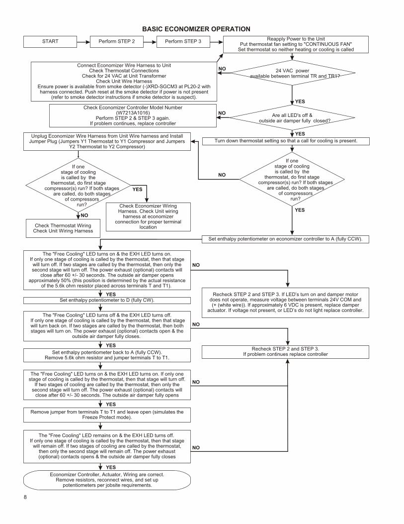
BASIC ECONOMIZER OPERATION
START Perform STEP 2 Perform STEP 3 Reapply Power to the UnitPut thermostat fan setting to "CONTINUOUS FAN"
Set thermostat so neither heating or cooling is called
24 VAC poweravailable between terminal TR and TR1?
Are all LED's off &outside air damper fully closed?
Check Economizer Controller Model Number(W7213A1016)
Perform STEP 2 & STEP 3 again.If problem continues, replace controller
Turn down thermostat setting so that a call for cooling is present.
If one stage of coolingis called by the
thermostat, do first stagecompressor(s) run? If both stages
are called, do both stagesof compressors
run?
Check Thermostat WiringCheck Unit Wiring Harness
Check Economizer WiringHarness. Check Unit wiring
harness at economizerconnection for proper terminal
location
Set enthalpy potentiometer on economizer controller to A (fully CCW).
The "Free Cooling" LED turns on & the EXH LED turns on.If only one stage of cooling is called by the thermostat, then that stage
will turn off. If two stages are called by the thermostat, then only thesecond stage will turn off. The power exhaust (optional) contacts will
close after 60 +/- 30 seconds. The outside air damper opensapproximately 50% (this position is determined by the actual resistance
of the 5.6k ohm resistor placed across terminals T and T1).
Set enthalpy potentiometer to D (fully CW).Recheck STEP 2 and STEP 3. If LED’s turn on and damper motor
does not operate, measure voltage between terminals 24V COM and(+ (white wire)). If approximately 6 VDC is present, replace damper
actuator. If voltage not present, or LED’s do not light replace controller.The "Free Cooling" LED turns off & the EXH LED turns off.
If only one stage of cooling is called by the thermostat, then that stage will turn back on. If two stages are called by the thermostat, then bothstages will turn on. The power exhaust (optional) contacts open & the
outside air damper fully closes.
Set enthalpy potentiometer back to A (fully CCW).Remove 5.6k ohm resistor and jumper terminals T to T1.
The "Free Cooling" LED turns on & the EXH LED turns on. If only onestage of cooling is called by the thermostat, then that stage will turn off.
If two stages of cooling are called by the thermostat, then only thesecond stage will turn off. The power exhaust (optional) contacts will
close after 60 +/- 30 seconds. The outside air damper fully opens
Remove jumper from terminals T to T1 and leave open (simulates theFreeze Protect mode).
The "Free Cooling" LED remains on & the EXH LED turns off. If only one stage of cooling is called by the thermostat, then that stage
will remain off. If two stages of cooling are called by the thermostat,then only the second stage will remain off. The power exhaust(optional) contacts opens & the outside air damper fully closes
Economizer Controller, Actuator, Wiring are correct.Remove resistors, reconnect wires, and set up
potentiometers per jobsite requirements.
Recheck STEP 2 and STEP 3.If problem continues replace controller
If one stage of coolingis called by the
thermostat, do first stagecompressor(s) run? If both stages
are called, do both stagesof compressors
run?
Unplug Economizer Wire Harness from Unit Wire harness and InstallJumper Plug (Jumpers Y1 Thermostat to Y1 Compressor and Jumpers
Y2 Thermostat to Y2 Compressor)
YES
NO
YES
NO
NO
NO
YES
YES
YES
YES
YES
YES
NO
NO
NO
NO
Connect Economizer Wire Harness to UnitCheck Thermostat Connections
Check for 24 VAC at Unit TransformerCheck Unit Wire Harness
Ensure power is available from smoke detector (-)XRD-SGCM3 at PL20-2 withharness connected. Push reset at the smoke detector if power is not present
(refer to smoke detector instructions if smoke detector is suspect).

9
HEAT PUMP OPERATION(Perform BASIC ECONOMIZER OPERATION check first)
START
Perform STEP 2
Perform STEP 3
Reapply Power to the UnitPut thermostat fan setting to "CONTINUOUS FAN"
Turn down thermostat setting so that a call for cooling is present.
Set enthalpy potentiometer on economizer controller to A (fully CCW).
The "Free Cooling" LED turns on & the EXH LED turns on.If only one stage of cooling is called by the thermostat, then that stage will turn off.If two stages are called by the thermostat, then only the second stage will turn off.
The power exhaust (optional) contacts will close after 60 +/- 30 seconds.The outside air damper opens approximately 50% (this position is determined bythe actual resistance of the 5.6k ohm resistor placed across terminals T and T1).
Reset the thermostat setting so that a call for heating is present.
The "Free Cooling" LED turns off & the EXH LED turns off.If only one stage of heating is called by the thermostat, then that stage will turn on.
If two stages are called by the thermostat, then both stages will turn on.The power exhaust (optional) contacts will open The outside air damper fully
closes.
Perform Basic Economizer Operation check first. Recheck STEP 2 and
STEP 3
Turn Min Pos potentiometer fully CW.
The outside air damper drives fully open. The EXH LED turns on.
The power exhaust (optional) contacts will close after approximately 60 +/- 30 seconds.
Check for 24 VAC at B terminal.Check for B signal at thermostat.
Check Unit wire harness.Check Economizer Wire harness.
Heat Pump Operation is Correct.Remove resistors, reconnect wires, and set up
potentiometers per jobsite requirements.
Replace controller.
YES
YES
YES
NO
NO
NO

10
Use the following graph and the multimeter to verify properoperation of the mixed air / discharge air temperaturesensor.
Measure the resistance (ohms) of the mixed air / discharge air temperature sensor with the multimeter. Look up theequivalent temperature on the graph. This should be thesame as temperature the mixed air / discharge air sensor is detecting. If it is not, replace the mixed air /discharge airsensor.
NOTES1. The mist eliminator (Permanent Outdoor Air Filter), is
of aluminum mesh construction and should becleaned by flushing regularly with warm soapy water.The replacement mist eliminator size is listed on thefirst page of these instructions.
2. When diagnosing the system, the best results areobtained by first putting the fan setting on theThermostat to the "Continuous Fan" mode.
3. Operation of the optional power exhaust only dependsupon the supply fan running and the damper position(it is possible to set the minimum position high enoughto engage the power exhaust in the heating mode).
4. This economizer requires a two-stage thermostat.
5. Upon loss of power to the unit or economizer, theoutside air damper will spring close shut in about 5seconds.
6. Compressor Time Delays, Compressor InterstageDelays, Compressor Low Ambient Lockouts, etc. arenot provided by the economizer controller.
RMIGE16SUPERSEDES 09-28-10OCTOBER 5, 2010

Mod u lat ing Gear Economizer(-)XRD-PGCM3
RKNL / RLNL 180-300 Without Smoke Detector
Notes:1. Unit wir ing shown as ref er ence only. Check unit wir ing for ac tual unit wir ing.2. Re lays 1K and 2K ac tu ate when the Out door Air Enthalpy is lower than the Re turn Air Enthalpy.3. 1S is an elec tronic switch which closes when pow ered by a 24 VAC in put.4. Fac tory in stalled re sis tor should be re moved only if C7400 Dif fer en tial Enthalpy Sen sor is added.5. Y2 must be en er gized for the com pres sor to op er ate.
WIRE COLOR CODE
BLK Black BLU BlueBRN Brown GRN GreenGRY Gray ORG OrangePNK Pink RED RedTAN Tan VIO VioletWHT White YEL Yellow
COMPONENT CODE
C7400A Fresh Air Sensor9RT1H Mixed Air SensorJ2 Power Exhaust CapMS7106K Damper Actuator 24vPL6 Male A/C Unit PlugPL7 Female A/C Unit PlugPL20 Female Economizer CapPL21 Male Smoke PlugW7213A Logic Module
Re vi sion Change Date
CONNECTOR & CONTACT CONFIGURATIONPL7 (303917) CAP - (303902) SOCKETJ2 (303909) CAP - (303902) SOCKET
HARNESS ENDS AT PL6 & PL7
Date: March 19, 2009
Supercedes:
Drawn by: MGL
Unit #: 60-364-16
Di a gram#: 6036416W
Ap proved by:

Mod u lat ing Gear Economizer(-)XRD-SGCM3
RKNL / RLNL 180-300 With Smoke Detector
Notes:1. Unit wir ing shown as ref er ence only. Check unit wir ing for ac tual unit wir ing.2. Re lays 1K and 2K ac tu ate when the Out door Air Enthalpy is lower than the Re turn Air Enthalpy.3. 1S is an elec tronic switch which closes when pow ered by a 24 VAC in put.4. Fac tory in stalled re sis tor should be re moved only if C7400 Dif fer en tial Enthalpy Sen sor is added.5. Y2 must be en er gized for the com pres sor to op er ate.
WIRE COLOR CODE
BLK Black BLU BlueBRN Brown GRN GreenGRY Gray ORG OrangePNK Pink RED RedTAN Tan VIO VioletWHT White YEL Yellow
C7400A Fresh Air Sensor9RT1H Mixed Air SensorJ2 Power Exhaust CapMS7106K Damper Actuator 24vPL6 Male A/C Unit PlugPL20 Female Economizer CapPL21 Male Smoke PlugPL22 Female Smoke CapW7213A Logic Module
Re vi sion Change Date
ECN 2258 Re moved 303H08 07-09-09
A Changed 303530 to 303528 09-30-09
A Changed 303533 to 303527 09-30-09
CONNECTOR & CONTACT CONFIGURATIONPL7 (303917) CAP - (303902) SOCKETJ2 (303909) CAP - (303902) SOCKET
HARNESS ENDS AT PL6
COMPONENT CODE
Date: Sep tem ber 30, 2009
Supercedes: 07-09-09
Drawn by: MGL
Unit #: 60-364-16S
Di a gram#: 6036416SW
Ap proved by: